Clustered Movable Pinching Antennas: Realizing Beamforming Gains and Target Diversity in ISAC Systems with Look-Angle-Dependent RCS
We investigate a novel integrated sensing and communication (ISAC) system enabled by pinching antennas (PAs), which are dynamically activated along a dielectric waveguide. Unlike prior designs, the PAs are organized into multiple clusters of movable …
Authors: Ata Khalili, Brikena Kaziu, Vasilis K. Papanikolaou
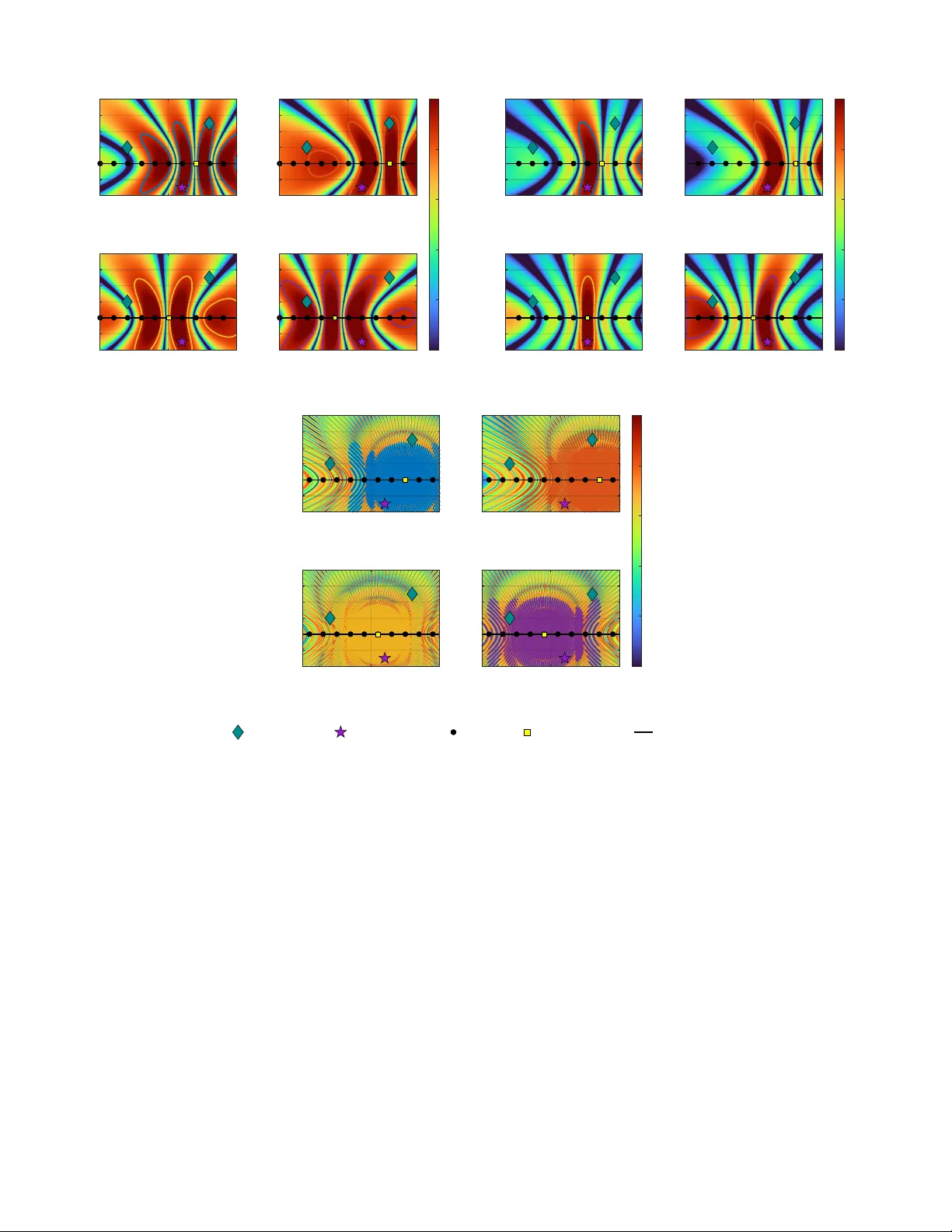
1 Clustered Mo v able Pinching Antennas: Realizing Beamforming Gains and T ar get Di v ersity in ISA C Systems with Look-Angle-Dependent RCS Ata Khalili, Member , IEEE , Brikena Kaziu, Gr aduate Student Member , IEEE , V asilis K. Papanikolaou, Member , IEEE , and Robert Schober , F ellow , IEEE Abstract —W e in vestigate a novel integrated sensing and com- munication (ISA C) system enabled by pinching antennas (P As), which are dynamically acti vated along a dielectric wa veguide. Unlike prior designs, the P As are organized into multiple clusters of movable antennas. The movement of the antennas within each cluster enables transmit beamforming, while the spatial separation of different clusters allows the system to illuminate the target from multiple angular perspectives. This approach provides two key benefits: (i) fine-grained beam steering within each cluster and (ii) angular diversity across clusters. For modeling the radar echo signals, we account for the dependence of the radar cross-section (RCS) on the illumination angle. Specifically , we model the RCSs seen from different illumination angles as correlated complex Gaussian random variables, reflecting the ph ysical continuity of the scattering behavior acr oss nearby angular dir ections. W e adopt the sensing outage probability as the key reliability metric, which quantifies the likelihood that the accumulated sensing signal- to-noise ratio (SNR) across time slots falls below a threshold. Accordingly , we minimize the sensing outage probability by jointly optimizing the P A cluster selection in each time slot, the antenna positions within the activated clusters, and the cluster activation durations, subject to average data rate constraints for the communication users. The resulting optimization problem is a non-con vex mixed integer non-linear program (MINLP). T o obtain a tractable solution, we derive a Chernoff-bound-based surrogate for the outage probability and develop an alternating optimization algorithm within a majorization–minimization (MM) framework, where the resulting subproblems are addr essed via successive conv ex approximation and penalty-based relaxation. Numerical results show that activating different P A clusters across time slots together with intra-cluster antenna movement for adaptive beamforming significantly reduces the sensing outage probability compared to (i) r eusing the same P A cluster across time slots, (ii) fixed-position antennas, and (iii) single-antenna activation per cluster . Our results further re veal an inherent sensing–communication trade-off, where stringent communication rate requirements limit the achievable sensing diversity . I . I N T R O D U C T I O N The sixth-generation (6G) wireless networks are envisioned to provide not only high-capacity and ultra-reliable commu- nications but also real-time en vironmental sensing. Integrated sensing and communication (ISA C) has therefore emerged as a key enabler by allowing spectrum, hardware, and infrastructure This work was supported by the Federal Ministry for Research, T echnology and Space (BMFTR) in Germany in the program of “Souver ¨ an. Digital. V er- netzt. ” joint project xG-RIC (Project-ID 16KIS2432), the Deutsche F orschungs- gemeinschaft (DFG, German Research Foundation) under project GRK-2680 – Project-ID 437847244, and Horizon Europe Marie Skołdo wska-Curie Actions (MSCA)-UNITE under project 101129618. This paper has been presented in part at the IEEE Global Communication Conference (Globecom) 2025 [1]. The authors are with the Institute for Digital Communications, Friedrich- Alexander -Univ ersity Erlangen–Nuremberg, 91054 Erlangen, German y (e-mail: { ata.khalili, brikena.kaziu, vasilis.papanikolaou, robert.schober } (@fau.de). to be shared between both functionalities. For ISAC, multiple- input multiple-output (MIMO) systems play a central role owing to their spatial processing gains that simultaneously enhance radar detection and communication reliability . How- ev er, conv entional MIMO architectures rely on fixed antenna arrays with limited aperture, which fundamentally constrains adaptability and spatial resolution, particularly in dynamic and cluttered en vironments. T o overcome these limitations, recent works hav e explored flexible antenna architectures such as fluid antennas and mov able antennas, which can reposition their radiating elements in real time to adapt to channel v ariations and thereby improve system performance [2]–[4]. Recently , pinching antennas (P As) ha ve emer ged as a promis- ing flexible-antenna paradigm leveraging dielectric wave g- uides [5], [6]. Unlike mechanically mov able arrays, P As en- able dynamic activ ation of radiating elements at preconfigured locations along the wav eguide without requiring physical dis- placement. This new architecture provides high spatial agility and scalability at low cost, while the extended aperture of the wa ve guide facilitates coverage ov er a wide area. Moreov er, the low propagation loss of dielectric wav eguides makes P As particularly attractiv e for establishing line-of-sight (LoS) links and mitigating signal blockages in comple x en vironments. Existing studies hav e demonstrated that P A-enabled systems can substantially outperform con ventional fixed antenna arrays in different communication settings [7], [8]. While ISA C provides substantial gains in terms of spectrum and infrastructure reuse, ensuring reliable radar performance is challenging due to the angle-dependent nature of the radar cross-section (RCS). In radar theory , it is well established that the RCS varies significantly with the look angle, depending on the target’ s shape, material, and orientation [9]. Although this phenomenon has been studied in the radar community , it is often neglected for ISA C design, where sensing channels are commonly modeled as deterministic or static [10]–[12]. As a result, when a target is probed from a single fixed direction, the performance may be compromised by weak echoes if the corresponding RCS happens to be small. T o mitigate this limitation, distributed MIMO radar architectures hav e been proposed, where spatially separated antennas observe the tar get from multiple viewpoints, thereby achieving tar get di- versity and improving detection robustness [13], [14]. Although distributed MIMO offers diversity , its implementation often requires costly and geographically separated infrastructure. A promising alternativ e is to exploit the flexibility of P As, which can facilitate multi-perspective illumination of a target through 2 dynamic acti vation along a dielectric wa veguide. Several recent studies have in vestigated P A-assisted ISA C. The authors of [15] proposed an integrated framework for P A systems, highlighting their potential for future 6G deployments. In [16], the emphasis was placed on the sensing accurac y of P A-enabled architectures, while the authors of [17] analyzed the achiev able rate region of P A-assisted ISA C. More recently , the Cram ´ er–Rao bound (CRB) was deri ved to characterize the fundamental sensing lim- its of P A-based ISA C systems [18]. This bound was extended to multi-wav eguide architectures providing enhanced spatial div ersity in [19]. Howe ver , the authors in [16]–[19] consider only a single, fixed P A configuration and ev aluate sensing performance within a single time slot, without accumulating sensing information across multiple time slots. Consequently , angular RCS di versity achiev ed through sequential activ ation of P As at different positions across time slots has not been exploited in these works. Motiv ated by the need to exploit angular RCS di versity for reliable sensing, the conference version of this paper [1], introduced a nov el P A-enabled ISA C framework where P As at dif ferent positions are sequentially acti vated across time slots, allowing the target to be illuminated from multiple look angles. Howe ver , the framework in [1] considered only a single communication user and relied on sev eral simplifying assumptions: (i) RCS realizations were modeled as independent across time slots, (ii) all time slots had equal duration, and (iii) only a single P A was activ ated in each time slot, which precluded transmit beamforming and limited the achiev able performance. T o ov ercome these limitations, in this paper , we extend our work in [1] and propose a novel P A architecture for ISAC systems, where the P As along the wa ve guide are organized into several clusters. Furthermore, we model the RCSs as correlated across look angles and serve multiple users. The main contributions of this work are summarized as follo ws: ‚ W e propose a novel ISAC architecture where multiple P A clusters are placed at fixed locations along a dielectric wa ve guide. Each cluster consists of multiple movable P As that are simultaneously activ ated. Only one cluster is activ ated per time slot and the corresponding P As are repo- sitioned within a predefined segment along the wav eguide to form a transmit beam toward the target. Different P A clusters illuminate the target with its angle-dependent RCS from dif ferent look angles, resulting in cluster-dependent RCS values, which are modeled as statistically correlated to capture the similarity of the scattering responses for nearby angles. ‚ W e formulate an optimization problem that facilitates the joint design of the P A cluster and communication user selection, intra-cluster P A positioning, and cluster activ ation duration, with the objective to minimize the sensing outage probability , while still ensuring the qual- ity of service (QoS) of the scheduled users. T o render the problem tractable, we derive the Chernoff bound on the sensing outage probability and dev elop an efficient iterativ e solution based on the majorization minimization (MM) framew ork. ‚ Our numerical results confirm that activ ating different T im e s lo t 1 T im e s lo t 2 2 3 T − 2 T PA el em ent C en t er 3 = ( 3 ,0 , ) C lu s te r 3 ULA DF RC- BS 2 = 2 u , 2 u , 0 1 = 1 u , 1 u , 0 . . . . . . . . . . . . . . . . . e = e , e , 0 1 2 3 1 T − 1 1 2 3 PA p os itio n op tim iz a ti o n I n iti a l po s itio n P o s si b l e P A mot i on d ir e c tio n O ptim iz e d po s itio n 1 2 3 ≥ mi n C l us t e r 1 C l us t e r 2 C l us t e r 3 2 1 = 1 1 2 = 1 3 1 = 0 3 2 = 1 1 1 = 1 1 2 = 0 2 1 = 0 2 2 = 0 U s e r 1 U s e r 2 Ta r g e t Fig. 1. Illustration of the considered downlink P A-assisted ISAC system with a DFRC-BS, dynamically activ ated P A clusters, multiple communication users, a radar receiv er , and a target. Σ p m q denotes the RCS coefficient for cluster m , which depends on the corresponding look angle θ m . P A clusters across time slots together with intra-cluster antenna mov ement for adaptiv e beamforming significantly reduces the sensing outage probability compared to (i) reusing the same P A cluster across time slots (ii) fixed position antennas, and (iii) single-antenna activ ation per cluster . Notation: In this paper , matrices and vectors are denoted by boldface capital letters A and boldface lower -case letters a , respectiv ely . A T , A ˚ , and A H denote the transpose, comple x conjugate, and Hermitian (conjugate transpose) of matrix A , respectiv ely . Rank p A q , T r p A q , and det p A q denote the rank, trace, and determinant of A , respectiv ely . diag p a q denotes a diagonal matrix whose diagonal entries are gi ven by the elements of vector a , while Diag p A q denotes a vector formed by extracting the main diagonal elements of matrix A . blkdiag p A 1 , ..., A n q denotes a block diagonal matrix composed of A 1 , ..., A n . A ľ 0 denotes a positiv e semidefinite matrix. I N is the N -by- N identity matrix. R N ˆ M and C N ˆ M represent the spaces of N ˆ M real-valued and complex-v alued matrices, respectiv ely . | ¨ | and || ¨ || 2 stand for the absolute value of a complex scalar and the l 2 -norm of a vector , respectiv ely . W e use vec t¨u to represent vectorization. 0 L and 1 L represent the all-zeros and all-ones column vectors of length L , respectiv ely . ℜ t¨u and ℑ t¨u denote the real and imaginary parts of a complex number , respectively . E r¨s refers to statistical expectation. I I . S Y S T E M M O D E L W e consider a downlink P A-enabled ISA C system compris- ing a dual-function radar-communication (DFRC) base station (BS), equipped with a P A array mounted on a dielectric wa ve guide, as illustrated in Fig. 1. The dielectric wave guide of length D x is deployed along the x -axis at a fixed height d above the ground. The P A elements along the wa veguide are organized into M spatially separated clusters, each com- prising a group of N T mov able P As. The center of the m - th P A cluster , m P M “ t 1 , . . . , M u , is preconfigured at p m “ r x m , 0 , d s P R 3 , and x m P r 0 , D x s . During each time slot t , t P T “ t 1 , . . . , T u , only one P A cluster is selected to serve one user k , k P K “ t 1 , . . . , K u , for do wnlink communication, while simultaneously probing a single static tar get. Time slot t is assigned a duration 3 τ p t q P r 0 , T max s , and the total time allocated across all slots is constrained as follows: T ÿ t “ 1 τ p t q ď T max . (1) User positions ψ k “ r x u k , y u k , 0 s P R 3 , k P K , and target position ψ e “ r x e , y e , 0 s P R 3 are assumed to be fixed during one transmission frame and are known at the DFRC-BS. Selecting dif ferent P A clusters in different time slots provides different angular views θ m , m P M , of the target over time, see Fig. 1. These different angular perspectives introduce targ et diversity , which is critical for ov ercoming the randomness and directionality of the RCS. T o be able to effecti vely suppress self-interference and enhance sensing performance, we assume that the radar echoes are collected at the DFRC-BS using a separate, fixed uniform linear array (ULA) equipped with N R antennas. A. Pinching Antenna Configuration In the proposed ISA C system, the transmit array is composed of multiple clusters of mov able P As distributed along a dielec- tric wave guide. Each cluster contains a small number of P As whose physical positions can be dynamically adjusted within the cluster . This architecture is intentionally designed to strike a balance between performance and practical deployability . While moving all antennas freely across the entire wa ve guide would maximize the spatial degrees of freedom (DoFs), such a configuration would incur prohibitiv e mechanical complexity , high latency , and susceptibility to positioning errors. Instead, we restrict antenna movement to within pre-designed cluster regions. This allows each cluster to independently perform flex- ible beam steering with low reconfiguration latency , enabling rapid adaptation to sensing and communication requirements without the need for coordinated mov ement across the entire wa ve guide. The N T P As of each cluster can slide continuously within a short linear aperture of length L , centered at position x m . This reconfigurable structure enables physical adjustment of antenna locations, offering fine spatial control over the trans- mitted wav efront and enabling beam steering without digital precoding. In each time slot t P T , a single cluster is activ ated to transmit the joint sensing and communication signal. Let b m p t q P t 0 , 1 u denote the corresponding binary activ ation variable, satisfying M ÿ m “ 1 b m p t q “ 1 , @ t P T . (2) The set of cluster centers x m is predesigned to ensure suf fi- ciently distinct look angles tow ard the target, ensuring that each cluster provides a unique spatial perspectiv e. Within the activ e cluster , the positions of the mov able antennas are optimized to form directional beams tow ard the communication user and the sensing target. Let x m,n P r x m ´ L { 2 , x m ` L { 2 s denote the po- sition of the n -th antenna of cluster m , where n P t 1 , . . . , N T u . T o av oid mutual coupling and physical overlap, the positions of the movable P As must satisfy a minimum spacing constraint, ensuring that the distance between any pair of P As remains abov e a predefined threshold as follows: x m,n ` 1 ´ x m,n ě d min , @ n, @ m. (3) By jointly optimizing the discrete cluster selection variables b m p t q and the continuous intra-cluster antenna positions x m,n , the proposed P A configuration can provide coarse angular div ersity across clusters and fine-grained beamforming within each cluster, benefiting both communication and sensing per- formance. B. T ransmit Signal Model In each time slot t , to maximize spectral efficienc y , the DFRC-BS transmits a single complex baseband wav eform that simultaneously carries communication data and performs radar probing. The transmitted signal is given by x p t q “ ? p T c p t q , (4) where c p t q P C is the information-bearing symbol intended for the user selected in time slot t , satisfying E r| c p t q| 2 s “ 1 , @ t , and p T P R ` is the transmit power of the BS. Signal c p t q is injected into the wave guide at the feed point p 0 “ r x 0 , 0 , d s . C. Communication Channel and Metric In the proposed P A-enabled ISA C system, the communica- tion channel is determined by both the free-space propagation from the acti ve P As to the users and the guided propagation inside the dielectric wave guide. As illustrated in Fig. 1, each P A radiates the signal launched from the feed point p 0 , where the signal first travels through the wa ve guide to the P A and then propagates through free space to the communication users. Hence, the composite channel consists of two physically distinct parts: ‚ W aveguide pr opagation: The signal experiences attenua- tion and phase shift while trav eling a guided distance of ℓ m,n “ } p 0 ´ x m,n } from the feed point to the n -th P A element of cluster m , where x m,n “ r x m,n , 0 , d s . The amplitude loss is modeled as e ´ αℓ m,n , where α is the wa ve guide attenuation coefficient, and the guided phase term e ´ j 2 π λ g ℓ m,n accounts for propagation with guided wa velength λ g “ λ { n eff , where λ and n eff are the free- space wav elength and the effecti ve refractiv e index of the dielectric material, respectiv ely . ‚ F r ee-space pr opagation: After radiation from the n -th P A of cluster m , the signal trav els distance d k,m,n “ } ψ k ´ x m,n } through the air to user k , experiencing joint free-space attenuation and phase rotation given by 1 d k,m,n e ´ j 2 π λ d k,m,n . By combining these two propagation ef fects, the ov erall complex baseband channel coef ficient from the feed point to user k , k P K , through the n -th P A of cluster m , is given by h k,m,n “ η d k,m,n ? N T e ´ αℓ m,n e ´ j ´ 2 π λ g ℓ m,n ` 2 π λ d k,m,n ¯ , (5) where η “ c 4 π f c is the free-space pathloss constant, c is the speed of light, and f c is the carrier frequency . The normaliza- tion factor 1 ? N T ensures that the total transmit power remains 4 constant independent of the number of P As per cluster , such that any performance gain results solely from coherent combining rather than power scaling. Eq. (5) reveals that changing the P A position x m,n simultaneously affects the guided phase, and the free-space phase, and thus the overall channel phase. This dependency of the phase on the P A position is fundamental to the beamforming capability of mo vable P As. Next, let us define the binary scheduling variable u k p t q P t 0 , 1 u , where u k p t q “ 1 indicates that user k is served in time slot t . T o ensure that at most one user is selected in each time slot, the following constraint is imposed: K ÿ k “ 1 u k p t q ď 1 . (6) Then, the receiv ed signal at user k is given by y k p t q “ M ÿ m “ 1 b m p t q N T ÿ n “ 1 h k,m,n ? p T c p t q ` z k p t q , (7) where z k p t q „ C N p 0 , σ 2 k q is additive white Gaussian noise (A WGN) with variance σ 2 k . Consequently , the instantaneous receiv ed SNR γ k p t q at scheduled user k , i.e., for u k p t q “ 1 , is giv en as follo ws: γ k p t q “ p T σ 2 k ˇ ˇ ˇ ˇ ˇ M ÿ m “ 1 b m p t q N T ÿ n “ 1 h k,m,n ˇ ˇ ˇ ˇ ˇ 2 . (8) D. Sensing Channel and Metric The sensing channel is affected by the same physical prop- agation phenomena as the communication channel, but also includes the reflection from the target. Specifically , the trans- mitted signal propagates along the dielectric wav eguide from the feed point to the activ e P A element, is radiated toward the target, and the reflected echo is collected by the fix ed recei ve ULA at the DFRC-BS. Accounting for both guided and free- space propagation, the baseband sensing channel coefficient between the n -th P A in cluster m and the tar get is given by h e ,m,n “ η } ψ e ´ x m,n } ? N T e ´ α } p 0 ´ x m,n } e ´ j ´ 2 π λ g } p 0 ´ x m,n }` 2 π λ } ψ e ´ x m,n } ¯ . (9) In the following, we introduce the correlated RCS model and deriv e the corresponding accumulated radar SNR and outage probability for the system model shown in Fig. 1 and the channel model giv en in (9). 1) Correlated RCS Modeling: In our system, the spatially distributed P A clusters illuminate the target from different angular directions. Specifically , each P A cluster m P M probes the target from a unique angle of incidence θ m , as illustrated in Fig. 1. Since the RCS of the target is highly dependent on the angle from which it is illuminated, each cluster experiences a different RCS. In contrast, the antennas within a single cluster are confined to a small spatial region of length L along the wa ve guide. Since L is small compared to the distance between the P A cluster and the target, the v ariation in the illumination angle across the P As within the same cluster is negligible. As a result, all P As within cluster m are assumed to illuminate the target from approximately the same look angle θ m and therefore experience the same effecti ve RCS, denoted by Σ p m q . T o capture the spatial v ariations of the RCS across different clusters, we model the RCS for the M clusters as a random vector [9]: Σ e “ r Σ p 1 q , Σ p 2 q , . . . , Σ p M qs T „ C N p 0 , R Σ q , (10) where R Σ P C M ˆ M is the co variance matrix that reflects the angular correlation between dif ferent RCSs. Follo wing estab- lished models in the literature [20]–[22], we use an exponential function to model the correlation between Σ p i q and Σ p j q , i, j P M : r R Σ s i,j “ ζ av e ´ κ | θ i ´ θ j | , i, j P M , (11) where ζ av “ E t} Σ e } 2 u is the average RCS power gain and κ ě 0 denotes the angular correlation decay rate that controls the degree of statistical similarity between the RCSs corresponding to different look angles. The resulting round-trip radar channel between the BS and the target can be expressed as follows: g p t q “ a r p θ e q d e , r M ÿ m “ 1 Σ p m q b m p t q N T ÿ n “ 1 h e ,m,n , (12) where d e , r is the distance between the target and the receive array , a r p θ e q P C N R is the receiv e steering vector aligned with the known direction of the target θ e [23]. The receiv ed echo at the DFRC-BS can be e xpressed as r e p t q “ g p t q x p t q ` z p t q , (13) where z p t q „ C N p 0 , σ 2 I N R q is the A WGN vector at the receiv e ULA with v ariance of σ 2 . The DFRC-BS applies a matched receiv e beamformer which is gi ven as follows: v “ a r p θ e q } a r p θ e q} , (14) and the resulting received radar signal is given by ˜ r e p t q “ v H r e p t q “ v H g p t q x p t q ` v H z p t q . (15) Then, the normalized instantaneous sensing SNR in time slot t , i.e., Γ p t q , @ t , can be e xpressed as: Γ p t q “ τ p t q T max ψ ˇ ˇ ˇ ˇ ˇ M ÿ m “ 1 b m p t q Σ p m q N T ÿ n “ 1 h e ,m,n ˇ ˇ ˇ ˇ ˇ 2 , (16) where the deterministic gain ψ is gi ven by ψ “ p T β 2 0 σ 2 d 2 e , r } a r p θ e q} 2 . (17) Note that in narro wband radar systems operating with con- stant transmit power p T , the receiv ed signal energy and hence the ef fectiv e SNR scale linearly with observation time τ p t q , @ t . Therefore, the inclusion of τ p t q in the SNR expression in (16) captures this physical reality where the radar echo strength increases proportionally with the time duration during which the target is illuminated [4]. By normalizing with respect to the total time budget T max (see (16)), we preserve unit consistency and ensure that Γ p t q represents the per-slot contribution to the ov erall accumulated sensing SNR. 5 2) Accumulated Sensing SNR and Outage Pr obability: T o assess the sensing performance ov er the entire transmission pe- riod T max , we consider the accumulated sensing SNR obtained by combining the sensing observations across all time slots. Specifically , the accumulated sensing SNR is given by Γ acc “ T ÿ t “ 1 Γ p t q “ ψ T ÿ t “ 1 τ p t q T max ˇ ˇ ˇ ˇ ˇ M ÿ m “ 1 b m p t q Σ p m q N T ÿ n “ 1 h e ,m,n ˇ ˇ ˇ ˇ ˇ 2 . (18) Since the cluster selection variables satisfy b m p t q P t 0 , 1 u and ř M m “ 1 b m p t q “ 1 , only one P A cluster is activ e in each time slot. As a result, the instantaneous sensing SNR can be simplified to Γ p t q “ ψ M ÿ m “ 1 τ p t q T max b m p t q ˇ ˇ ˇ ˇ ˇ N T ÿ n “ 1 h e ,m,n ˇ ˇ ˇ ˇ ˇ 2 | Σ p m q| 2 . (19) Then, the total sensing SNR in (18) can be expressed as Γ acc “ M ÿ m “ 1 q m | Σ p m q| 2 , (20) where the deterministic weight associated with cluster m is defined as q m fi ψ T ÿ t “ 1 τ p t q T max b m p t q ˇ ˇ ˇ ˇ ˇ N T ÿ n “ 1 h e ,m,n ˇ ˇ ˇ ˇ ˇ 2 . (21) Since Σ p m q is modeled as a correlated complex Gaussian random variable, see (10), | Σ p m q| 2 follows a correlated ex- ponential distribution. As a result, Γ acc is a weighted sum of correlated non-identically exponentially distrib uted random variables, see (20). T o model the reliability of the sensing pro- cess, we adopt the sensing outage probability as performance metric, defined as: P out “ Pr ` Γ acc ă Γ th ˘ , (22) where Γ th denotes the minimum SNR threshold required for successful target detection. Given the statistical uncertainty induced by the randomness of the RCS, the probabilistic formulation in (22) provides a rigorous metric for assessing sensing performance while explicitly accounting for the RCS correlations across different P A clusters. I I I . P R O B L E M F O R M U L A T I O N W e aim to jointly optimize antenna cluster selection, user scheduling, intra-cluster antenna positioning, and time alloca- tion for minimization of the sensing outage probability , while the long-term communication QoS must be guaranteed for the scheduled users. The sensing outage probability captures the likelihood that the sensing SNR accumulated across all time slots falls below detection threshold Γ th , resulting in unreliable target detection. The randomness of the RCS in- troduces stochastic uncertainty regarding the receiv ed echoes. By activ ating different spatially separated P A clusters along the wa ve guide in different time slots and adjusting the antenna positions within each acti vated cluster , angular di versity and a beamforming gain are realized, respectively , which improv es sensing reliability . The resulting optimization problem is for - mulated as follows P 0 : minimize t b m p t q , τ p t q , u k p t q , x m,n u F fi Pr ` Γ acc ă Γ th ˘ s.t. C1: T ÿ t “ 1 τ p t q T max u k p t q log 2 p 1 ` γ k p t qq ě R min , @ k P K , C2: M ÿ m “ 1 b m p t q “ 1 , @ t P T , C3: T ÿ t “ 1 τ p t q ď T max , τ p t q ě T min , @ t P T , C4: b m p t q P t 0 , 1 u , @ m P M , t P T , C5: u k p t q P t 0 , 1 u , @ k P K , t P T , C6: K ÿ k “ 1 u k p t q ď 1 , @ t P T , C7: x m,n ` 1 ´ x m,n ě d min , @ n, @ m P M , (23) where C1 ensures that the av erage communication rate meets the required minimum data rate R min . C2 enforces that only one cluster is activ ated in each time slot t . Constraint C3 ensures that the total time allocated across all time slots does not e xceed the overall budget T max . At the same time, each individual time slot duration τ p t q must be no smaller than a minimum threshold T min , which accounts for hardware and processing limitations (e.g., minimum actuation or integration time). C4 and C5 guarantee binary cluster selection and user scheduling decisions, respectiv ely . C6 ensures that at most one user is serv ed in each time slot. Finally , C7 enforces a minimum separation d min between any two P As within each cluster to mitigate mutual coupling and ensure stable beamforming. Problem P 0 is non-conv ex due to the probabilistic objective function, the binary cluster selection variables, the binary user scheduling variables, and the coupling between antenna positioning and time-slot allocation. In the next section, we deriv e a tractable solution for P 0 based on a Chernoff-bound approximation and the MM approach. I V . P RO P O S E D S O L U T I O N Direct ev aluation of the sensing outage probability is chal- lenging because the accumulated sensing SNR Γ acc is a weighted sum of statistically dependent RCS power terms, | Σ p m q| 2 , @ m , see (20). T o enable a tractable analysis, let us first express the accumulated sensing SNR Γ acc as a quadratic form. Specifically , by defining Q “ diag p q 1 , . . . , q M q , the accumulated sensing SNR can be compactly written as Γ acc “ Σ H e QΣ e . (24) This representation enables the application of a Chernoff- bound-based approximation, which yields an analytically tractable upper bound on the sensing outage probability while explicitly accounting for the angle-dependent RCS statistics. Using the Chernoff bound for complex Gaussian quadratic forms [1], [24], the outage probability can be upper-bounded as follows: P out ď min s ą 0 " e s Γ th 1 det p I M ` s R Σ Q q * (25) 6 Original problem P 0 Chernoff-bound surrogate of radar outage probability (parameterized by s > 0) Outer loop over s ∈ S Inner AO loop (fixed s ) Subproblem 1: Cluster activation & durations T echniques: Big- M , SCA V ariables: { b m ( t ) , τ ( t ) , p m ( t ) } Subproblem 2: Beamforming & user scheduling Subproblem 2a (MM/SCA): P A positioning & b eamforming { x m,n ( t ) , ρ k ( t ) , F j , A j } Subproblem 2b (Big- M ): Scheduling & QoS variables { u k ( t ) , ρ k ( t ) , ˜ ρ k ( t ) } Conv erged? Ev aluate surrogate for current s Update best solution if improved Select s ⋆ = arg min s ∈S surrogate Output final solution yes no next s Outer lo op over s Inner AO loop (fixed s ) Fig. 2. Block diagram of the proposed solution to problem P 0 based on the A O-based Algorithm 1. T aking the logarithm of the argument in (25) yields the following surrogate objectiv e function: min s ą 0 ␣ s Γ th ´ log det p I M ` s R Σ Q q ( . (26) In the following, for a fixed Chernoff parameter s , the resulting surrogate problem is solved using an alternating optimization (A O) framework. In this framework, the surrogate problem is partitioned into two tractable subproblems that are optimized iteratively until con vergence. Specifically , the first subproblem optimizes the P A cluster selection and time slot du- ration, while the second subproblem optimizes the intra-cluster antenna positions and performs communication user schedul- ing. The continuous subproblems are addressed within an MM framew ork implemented via successive con vex approximation (SCA), while the discrete variables are handled using big-M relaxation. Since the Chernoff-bound-based surrogate depends on the scalar parameter s ą 0 , we perform a one-dimensional search over a finite grid of candidate v alues. For each candidate s , the A O procedure is executed until conv ergence, and the solution yielding the smallest surrogate value is selected. The ov erall solution procedure, including the outer search ov er s and the inner alternating updates, is summarized in Fig. 2. A. Subproblem 1: Cluster Selection and Activation Duration Optimization In the first subproblem, for given P A positions and scheduled users, we jointly optimize the binary cluster selection variables b m p t q and acti vation durations τ p t q for all time slots. The problem can be formulated as follows P 1 : minimize b m p t q ,τ p t q s Γ th ´ log det p I M ` s R Σ Q q (27) s.t. C1 , C2 , C3 , C4 . The above problem is still non-con ve x. The non-conv exity arises from two sources: (i) the log-determinant term, which depends on the binary variables b m p t q through Q , and (ii) the bilinear terms τ p t q b m p t q . T o address (i), we apply a first-order T aylor approximation in SCA iteration l . W e define A p l q fi I M ` s R Σ Q p l q , then log det p I M ` s R Σ Q q ď log det ´ A p l q ¯ ` T r ˆ ´ A p l q ¯ ´ 1 s R Σ p Q ´ Q p l q q ˙ . (28) T o handle the bilinear term τ p t q b m p t q , we introduce auxiliary variables: p m p t q fi τ p t q b m p t q , @ m, t, (29) and impose the following big-M constraints: C8 : 0 ď p m p t q ď T max b m p t q , @ m, t, (30) C9 : τ p t q ´ p 1 ´ b m p t qq T max ď p m p t q ď τ p t q , @ m, t. (31) Next, we relax the binary constraint b m p t q P t 0 , 1 u and rewrite C4 as follows: C4a : 0 ď b m p t q ď 1 , (32) C4b : M ÿ m “ 1 T ÿ t “ 1 ´ b m p t q ´ ` b m p t q ˘ 2 ¯ ď 0 . (33) Constraint C4b is a dif ference of con ve x (DC) functions, and we use the first-order T aylor expansion to con vert this non-con vex constraint to the following con vex constraint y C4b : M ÿ m “ 1 T ÿ t “ 1 ´ b m p t q ´ b p l q m p t q ¯ ´ 2 b p l q m p t q ´ b m p t q ¯ ď 0 . (34) Now , we introduce a penalty factor ρ to mov e constraint C4b to the objectiv e function, where ρ represents the relativ e impor - tance of recov ering binary values for b m p t q . For a sufficiently large value of ρ , optimization problem P 1 is equiv alent to the following con ve xified Subproblem 1 in iteration l : P p l q 1 : minimize b m p t q ,τ p t q ,p m p t q s Γ th ´ log det ´ A p l q ¯ ´ T r ˆ ´ A p l q ¯ ´ 1 s R Σ p Q ´ Q p l q q ˙ ` ρ M ÿ m “ 1 T ÿ t “ 1 ´ b m p t q ´ b p l q m p t q ¯ ´ 2 b p l q m p t q ´ b m p t q ¯ s.t. C1: T ÿ t “ 1 p m p t q T max u k p t q log 2 p 1 ` γ k p t qq ě R min , @ k , C2: M ÿ m “ 1 b m p t q “ 1 , @ t, C3: T ÿ t “ 1 τ p t q ď T max , τ p t q ě T min , @ t, C4a: 0 ď b m p t q ď 1 , @ m, t, C8-C9 . (35) This subproblem is conv ex and can be optimally solved via known con ve x solvers such as CVX [25]. 7 B. Subproblem 2: Beamforming via Movable P As and User Scheduling Giv en the selected P A clusters and activ ation times from Subproblem 1, we next optimize the intra-cluster antenna positions x m,n and the binary user scheduling variables u k p t q . This subproblem is formulated as follows: P 2 : minimize u k p t q , x m,n s Γ th ´ log det p I M ` s R Σ Q q s.t. C1 , C5 , C6 , C7 . (36) The free-space distance between the n -th P A and a generic node o P t k , e u , where k and e index the communication users and the target, respectiv ely , is given by d o,m,n “ ˇ ˇ ψ o ´ x m,n ˇ ˇ “ b ` x m,n ´ x o ˘ 2 ` y 2 o ` d 2 , (37) and the wa ve guide feed-to-antenna distance is ℓ m,n . For analytical con venience, we separate the amplitude and phase components of the channel. Specifically , the channel between the n -th antenna of cluster m and user k is decomposed as f m,n,k fi 1 d k,m,n and a m,n,k fi e ´ j θ m,n,k , where the phase is giv en by θ m,n,k “ 2 π λ d k,m,n ` 2 π λ g ℓ m,n . For each cluster, define the vectors f m,k “ r f m, 1 ,k , . . . , f m,N T ,k s T P R N T and a m,k “ r a m, 1 ,k , . . . , a m,N T ,k s T P C N T , and matrix C m “ diag p η e ´ αℓ m, 1 , . . . , η e ´ αℓ m,N T q . Stacking across clusters yields f k “ vec t f 1 ,k , . . . , f M ,k u , a k “ vec t a 1 ,k , . . . , a M ,k u , and C “ blkdiag p b 1 p t q C 1 , . . . , b M p t q C M q . W e further define F k “ f k f H k and A k “ a k a H k . Besides, we also introduce the auxiliary v ariable ρ k p t q to bound the SNR for the communication user as follows p T σ 2 k ˇ ˇ ˇ ˇ ˇ M ÿ m “ 1 b m p t q N T ÿ n “ 1 h k,m,n ˇ ˇ ˇ ˇ ˇ 2 ě ρ k p t q ě 0 . (38) Since b m p t q P t 0 , 1 u and ř M m “ 1 b m p t q “ 1 , exactly one cluster is active in each time slot. Hence, the term ř M m “ 1 b m p t q h k,m,n selects the channel coefficient corresponding to the activ e cluster only . Using the matrix representation of the effecti ve channel, we have ˇ ˇ ˇ ˇ ˇ N T ÿ n “ 1 M ÿ m “ 1 b m p t q h k,m,n ˇ ˇ ˇ ˇ ˇ 2 “ T r ` C H A k CF k ˘ . T o obtain a tractable reformulation, we use the Frobenius iden- tity } X ` Z } 2 F “ } X } 2 F ` } Z } 2 F ` 2 ℜ t T r p X H Z qu . Rearranging this identity giv es ℜ t T r p X H Z qu “ 1 2 ` } X ` Z } 2 F ´ } X } 2 F ´ } Z } 2 F ˘ . Applying this result with X “ F k and Z “ C H A k C , the SNR for the communication users can be written as C1a: } F k ` C H A k C } 2 F ´ } F k } 2 F ´ } C H A k C } 2 F ě 2 σ 2 k p T ρ k p t q . (39) As a result, P 2 can be reformulated as: minimize x m,n , u k p t q ,ρ k p t q , F o , A o ,θ ι p n,m q ,o s Γ th ´ log det ` I M ` s R Σ Q ˘ s.t. C1a , C1b: T ÿ t “ 1 u k p t q τ p t q T max log 2 ` 1 ` ρ k p t q ˘ ě R min , @ k , C6: K ÿ k “ 1 u k p t q ď 1 , C5: u k p t q P t 0 , 1 u , @ k , t, C10 : ` x m,n ´ x o ˘ 2 “ 1 Diag p F o q ι p n,m q ´ ˆ s n,o , @ n, m, o, ˆ s n,o fi y 2 o ` d 2 , C11 : r A o s ι p n,m q , ι p n 1 ,m 1 q “ e ´ j ` θ ι p n,m q ,o ´ θ ι p m 1 ,n 1 q ,o q ˘ , @ n, m, n 1 , m 1 , o, C12 : θ ι p n,m q ,o “ 2 π λ ` Diag p F o q ι p n,m q ˘ ´ 1 2 ` 2 π λ g ℓ m,n , @ n, m, o, ℓ m,n “ › › x m,n ´ p 0 › › , @ n, m, C13 : F o ľ 0 , A o ľ 0 , @ o, C14 : rank p F o q “ 1 , rank p A o q “ 1 , @ o, (40) where ι p n, m q “ p m ´ 1 q N T ` n P t 1 , . . . , N tot u , with N tot “ N T M , maps indices from a two-dimensional to a single-dimensional stacked vector and Diag p F k q ι p n,m q “ r F k s ι p n,m q ,ι p n,m q for simplicity of notation. W e first address the non-conv ex equality constraints C10 and C12. Each can be written as a pair of equiv alent inequalities. For C10, we have C10a : p x m,n ´ x o q 2 ´ 1 Diag p F o q ι p n,m q ` ˆ s n,o ď 0 , @ m, n, o P t k , e u , (41) C10b : 1 Diag p F o q ι p n,m q ´ ˆ s n,o ´ p x m,n ´ x o q 2 ď 0 , @ m, n, o P t k , e u . (42) Like wise, C12 becomes C12a : 2 π λ ` Diag p F o q ι p n,m q ˘ ´ 1 2 ` 2 π λ g ℓ m,n ´ θ ι p n,m q ,o ď 0 , (43) C12b : θ ι p n,m q ,o ´ 2 π λ ` Diag p F o q ι p n,m q ˘ ´ 1 2 ´ 2 π λ g ℓ m,n ď 0 . (44) Constraints C10 and C12 are replaced by two respectiv e sub- constraints: the first subconstraints (C10a and C12a) are conv ex, whereas the second subconstraints (C10b and C12b) are DC constraints. Lemma 1: For any Hermitian X ľ 0 , rank p X q “ 1 if and only if } X } ˚ ´ } X } 2 “ 0 , where } X } ˚ denotes the trace norm [26]. Utilizing Lemma 1, C14 can be equi valently written as C14 : } A o } ˚ ´ } A o } 2 ď 0 , } F o } ˚ ´ } F o } 2 ď 0 , @ o P t k , e u . (45) W ithout loss of generality , we parameterize A k by its first nonzero column. Using trigonometric identities, C11 is equi v- alently expressed as C11a : ℜ pr A k s i, 1 q “ cos p ˆ θ i,k q , i P t 2 , . . . , N tot u , (46) C11b : ℑ pr A k s i, 1 q “ ´ sin p ˆ θ i,k q , i P t 2 , . . . , N tot u , (47) where ˆ θ i,k “ θ i,k ´ θ 1 ,k . T o softly enforce constraints C11a and C11b, we add a quadratic penalty term to the objectiv e function of the conv ex surrogate problem constructed using the MM framew ork: Φ ´ r A k s i, 1 , ˆ θ i,k ¯ “ ˇ ˇ ℜ pr A k s i, 1 q ´ cos ˆ θ i,k ˇ ˇ 2 ` ˇ ˇ ℑ pr A k s i, 1 q ` sin ˆ θ i,k ˇ ˇ 2 , (48) with a penalty coefficient ϱ 1 ą 0 , and minimize the penalized objectiv e function subject to the remaining constraints. The resulting penalized problem reads minimize x m,n , u k p t q ,ρ k p t q , F o , A o ,θ ι p n,m q ,o s Γ th ´ log det ` I M ` s R Σ Q ˘ ` 8 ϱ 1 K ÿ k “ 1 N tot ÿ i “ 2 Φ ´ r A k s i, 1 , ˆ θ i,k ¯ s.t. C1 , C5 , C6 , C10a ´ C12b , C13 , C14 . (49) Problem (49) and the original formulation in (40) are equiv alent when ϱ 1 is suf ficiently large. Although (49) is still non-conv ex, it admits a standard MM approach [27]. In SCA iteration l , let z m,n,k “ Diag p F k q ι p n,m q and define S p l q k fi F p l q k ` C p x p l q q H A p l q k C p x p l q q . (50) Using first-order T aylor surrogates in the current iteration l , we obtain the following global under-estimators for the DC terms: › › F k ` C H A k C › › 2 F “ } S p l q k } 2 F ` 2 Tr ` p S p l q k q H p F k ´ F p l q k q ˘ ` 2 Tr ` p S p l q k q H C p x p l q q H p A k ´ A p l q k q C p x p l q q ˘ , (51) x aff m,n,k “ p x p l q m,n ´ x k q 2 ` 2 p x p l q m,n ´ x k qp x m,n ´ x p l q m,n q , (52) z aff m,n,k “ 1 z p l q m,n,k ´ z m,n,k ´ z p l q m,n,k p z p l q m,n,k q 2 , (53) z aff m,n,k “ 2 π λ p z p l q m,n,k q ´ 1 2 ´ π λ p z p l q m,n,k q ´ 3 2 ` z m,n,k ´ z p l q m,n,k ˘ . (54) For the rank surrogates in C14, we linearize the spectral norm at Y p l q o ( Y P t A , F u ): } Y o } 2 ě } Y p l q o } 2 ` Tr ´ Φ max p Y p l q o q Φ H max p Y p l q o q ` Y o ´ Y p l q o ˘ ¯ , (55) where Φ max p¨q denotes the principal right singular vector . Similarly , we apply the MM technique along with a Lips- chitz gradient surrogate to establish a global upper bound for Φ ´ r A k s i, 1 , ˆ θ i,k ¯ Φ p l q i,k “ 2 ´ ˆ ℜ p l q i,k sin ˆ θ p l q i,k ` ˆ ℑ p l q i,k cos ˆ θ p l q i,k ¯ ∆ ˆ θ i,k ` 2 ˆ ℜ p l q i,k ∆ ℜ i,k ` 2 ˆ ℑ p l q i,k ∆ ℑ i,k ` L AR 2 p ∆ ℜ i,k q 2 ` L AI 2 p ∆ ℑ i,k q 2 ` L TH 2 p ∆ ˆ θ i,k q 2 ` Φ p l q i,k , (56) where ˆ ℜ p l q i,k “ ℜ pr A k s p l q i, 1 q ´ cos ˆ θ p l q i,k , ˆ ℑ p l q i,k “ ℑ pr A k s p l q i, 1 q ` sin ˆ θ p l q i,k , ∆ ˆ θ i,k “ ˆ θ i,k ´ ˆ θ p l q i,k , ∆ ℜ i,k “ ℜ pr A k s i, 1 q ´ ℜ pr A k s p l q i, 1 q , and ∆ ℑ i,k “ ℑ pr A k s i, 1 q´ ℑ pr A k s p l q i, 1 q , with Lipschitz constants L AR “ L AI “ 2 and L TH “ 4 . In addition, since the mapping Q ÞÑ log det p I M ` s R Σ Q q is concave in Q , we linearize it at Q p l q : log det p I M ` s R Σ Q q ď log det ´ A p l q ¯ ` T r ˆ ´ A p l q ¯ ´ 1 s R Σ p Q ´ Q p l q q ˙ , (57) which preserves the con ve xity of the MM subproblem. Collect- ing all surrogates, in the p l ` 1 q -th SCA iteration, the following con vex problem has to be solved. minimize x m,n , u k p t q , ρ k p t q , F o , A o , θ ι p n,m q ,o s Γ th ´ log det ´ A p l q ¯ ´ T r ˆ ´ A p l q ¯ ´ 1 s R Σ ` Q ´ Q p l q ˘ ˙ ` ϱ 1 K ÿ k “ 1 N tot ÿ i “ 2 Φ p l q i,k s.t. C1a : } F k ` C H A k C } 2 F 2 ´ } F k } 2 F 2 ´ } C H A k C } 2 F 2 ´ N T σ 2 k p T ρ k p t q ě 0 , @ k , t, C10a : p x m,n ´ x o q 2 ´ z aff m,n,o ` ˆ s n,o ď 0 , @ m, n, o, C10b : 1 Diag p F o q ι p n,m q ´ ˆ s n,o ´ x aff m,n,o ď 0 , @ m, n, o, C12a : θ ι p n,m q ,o ´ z aff m,n,o ´ 2 π λ g ℓ m,n ď 0 , @ m, n, o, C12b : 2 π λ ` Diag p F o q ι p n,m q ˘ ´ 1 { 2 ` 2 π λ g ℓ m,n ´ θ ι p n,m q ,o ď 0 , @ m, n, o, y C14 : } Y o } ˚ ´ ´ } Y p l q o } 2 ` T r ` Φ max Φ H max p Y o ´ Y p l q o q ˘ ¯ ď 0 , Y o P t A o , F o u , @ o, C1b , C5 , C6 , C7 . (58) Here, x aff m,n,o , z aff m,n,o , and z aff m,n,o denote the af fine MM surro- gates in the current iteration. C. Proposed BCD-Based Solution The reformulated problem in (58) remains challenging due to the coupling between optimization variables x m,n , F o , A o , and the binary user scheduling variables u k p t q . T o ef ficiently solve it, we adopt a Block Coor dinate Descent (BCD) approach by partitioning the optimization variables into two subproblems that are alternately updated. The two subproblems are solved iterativ ely until con ver gence: 1) Step 1: Solve Subproblem 2a via the MM approach to update x m,n , F o , A o , θ o,m,n , and ρ k p t q . 2) Step 2: Solve Subproblem 2b via a big-M-based conv ex problem with penalty factor to update u k p t q and ρ k p t q . Subpr oblem 2a (P A P osition and Amplitude–Phase Block): In this subproblem, we optimize x m,n , F o , A o , θ o,m,n , and the auxiliary SNR variables ρ k p t q while fixing the user scheduling u k p t q . The corresponding optimization problem is formulated as minimize x m,n , ρ k p t q , F o , A o ,θ ι p n,m q ,o s Γ th ´ log det p I M ` s R Σ Q p l q q´ T r ´ G p l q ` Q ´ Q p l q ˘ ¯ ` ϱ 1 K ÿ k “ 1 N tot ÿ i “ 2 Φ p l q i,k s.t. C1a , C1b , C7 , C10a , C10b , C12a , C12b , y C14 , F o ľ 0 , A o , ľ 0 , @ o. (59) This subproblem is con ve x and can be solved efficiently using CVX [25], [28]. Subpr oblem 2b (User Scheduling and QoS Block): In this subproblem, the P A positions and amplitude-phase v ariables are fixed to the v alues obtained in Subproblem 2a. W e then optimize the user scheduling u k p t q and the communication SNR ρ k p t q . T o handle the binary nature of u k p t q , we adopt a big- M formulation by introducing the auxiliary variable ˜ ρ k p t q fi ρ k p t q u k p t q , while imposing the follo wing constraints C15 : 0 ď ˜ ρ k p t q ď ρ k p t q , (60) 9 C16 : 0 ď ˜ ρ k p t q ď ρ max u k p t q , (61) C17 : ρ k p t q ´ p 1 ´ u k p t qq ρ max ď ˜ ρ k p t q , (62) where ρ max “ 2 R min ´ 1 . As a result, the per-user QoS constraint in C1b becomes y C1b : T ÿ t “ 1 τ p t q T max log 2 ` 1 ` ˜ ρ k p t q ˘ ě R min , @ k . (63) Next, we relax the scheduling v ariable as 0 ď u k p t q ď 1 and rewrite C5 as follows: C5a: 0 ď u k p t q ď 1 , (64) C5b: ÿ k,t u k p t qp 1 ´ u k p t qq ď 0 . (65) Constraint C5b is a DC function, and we use the first-order T aylor expansion to con vert the non-con vex constraint to the following con ve x constraint z C5b: K ÿ k “ 1 T ÿ t “ 1 ´ u p l q k p t qp 1 ´ u p l q k p t qq ` p 1 ´ 2 u p l q k p t qq ` u k p t q ´ u p l q k p t q ˘ ¯ ď 0 . (66) T o promote binary scheduling, we introduce a penalty term with parameter ϱ 2 ą 0 . The resulting optimization problem in iteration l is formulated as min t u k p t q ,ρ k p t q , ˜ ρ k p t qu s Γ th ´ log det p I M ` s R Σ Q q ` ϱ 2 K ÿ k “ 1 T ÿ t “ 1 ´ u p l q k p t qp 1 ´ u p l q k p t qq ` p 1 ´ 2 u p l q k p t qq ` u k p t q ´ u p l q k p t q ˘ ¯ (67) s.t. C1a , y C1b , C5a , C6 , C15 ´ C17 . This subproblem is con ve x and can be solved efficiently using CVX [25], [28]. D. Conver gence Analysis For a fixed Chernoff parameter s , the proposed algorithm updates three blocks of v ariables in an alternating fashion: (i) P A-cluster selection and time slot durations ( Subproblem 1 in Algorithm 1 ), (ii) intra-cluster P A antenna positions and their corresponding beamforming matrices ( Subproblem 2a in Algorithm 1 ), and (iii) user scheduling along with the SNR auxiliary variables ( Subproblem 2b in Algorithm 1 ). In each subproblem, one set of variables is updated while the others are held fixed. The conv ergence of the proposed alternating proce- dure follows from the MM principle applied to the Chernoff- bound surrogate problem. In each iteration, a con ve x surrogate that upper-bounds the main objecti ve and coincides with it at the current point is minimized. This guarantees a non-increasing sequence of surrogate objecti ve v alues. Since the surrogate objectiv e is bounded from below , the sequence con ver ges to a stationary point of the surrogate problem. Solving each con vexified subproblem, therefore, yields a solution that does not increase the value of the surrogate objecti ve. As a result, the sequence of objecti ve values, denoted by t F p l q p s qu at iteration l for fixed s , is monotonically non-increasing. Since the objective is bounded below (e.g., by zero in the case of the outage probability surrogate), the sequence F p l q p s q con ver ges. Moreov er , for sufficiently large penalty factors associated with Algorithm 1 MM-based Outage Minimization with Chernoff Bound 1: Input: System parameters t M , N T , K, T max u , Chernoff grid S “ t s 1 , . . . , s S u , maximum number of iterations L max , and tolerance ε . 2: Initialize: Best objective value F ˚ Ð `8 . 3: for all s P S do 4: Initialize: Cluster selection b p 0 q m p t q , time allocation τ p 0 q p t q , P A positions x p 0 q m,n p t q , user scheduling u p 0 q k p t q , SNR variables ρ p 0 q k p t q , and iteration index l Ð 0 . 5: repeat 6: [Subproblem 1: Cluster Selection and Time Allo- cation] Fix t x p l q m,n p t q , u p l q k p t qu and solve the conv exified problem (35) to update t b p l ` 1 q m p t q , τ p l ` 1 q p t qu . 7: [Subproblem 2: Beamforming and User Schedul- ing] (a) P A P osition and Beamforming Update: For fixed t u p l q k p t qu , solve the MM–based conv ex subproblem (59) to update t x p l ` 1 q m,n p t q , F p l ` 1 q o , A p l ` 1 q o , θ p l ` 1 q o,m,n , ρ p l ` 1 q k p t qu . (b) User Scheduling Update: For fix ed t x p l ` 1 q m,n p t q , F p l ` 1 q o , A p l ` 1 q o , θ p l ` 1 q o,m,n u , solve the big-M-based con vex problem (67) with MM-linearized binary penalty to update t u p l ` 1 q k p t q , ρ p l ` 1 q k p t qu . 8: Update: l Ð l ` 1 . 9: until Con ver gence, or l “ L max | F p l q p s q ´ F p l ´ 1 q p s q| | F p l ´ 1 q p s q| ă ε, where F p l q p s q is the Chernoff-bound objecti ve in itera- tion l for parameter s . 10: Store best solution: If F p l q p s q ă F ˚ , then set F ˚ Ð F p l q p s q and store V ˚ Ð t b m p t q , τ p t q , x m,n p t q , u k p t q , ρ k p t qu . 11: end f or 12: Output: Optimized solution V ˚ “ t b ˚ m p t q , τ ˚ p t q , x ˚ m,n p t q , u ˚ k p t q , ρ ˚ k p t qu . the binary relaxation terms, i.e., ϱ 1 in (49), ϱ 2 in (67), and ρ in (35), the surrogate updates satisfy the regularity conditions required for conv ergence to a stationary point, as established in [4], [23], [29]. Thus, each iteration impro ves or maintains the surrogate objectiv e value, and the algorithm con ver ges to a stationary solution of the surrogate problem for any fixed s . The outer loop of the algorithm performs a one-dimensional search ov er a finite grid of values for the Chernoff parameter s . For each candidate s , the A O procedure is executed until con vergence (see line 9 in Algorithm 1 ). Finally , the solution that yields the smallest surrogate objecti ve value among all candidate s values is selected. This ensures a tractable and high-quality approximation to the original outage minimization 10 T ABLE I S I MU L A T I O N P AR A M E TE R S Parameter V alue Parameter V alue W av eguide length ( D x ) 10 m Number of pinching clusters ( M ) 10 Number of users 2 T otal time ( T max ) 8 ms Receiv e antennas ( N R ) 8 SNR threshold ( Γ th ) 10 dB Noise po wer ( σ 2 k “ σ 2 ) –90 dBm A verage RCS power gain ( ζ av ) 1 m 2 Carrier frequency ( f c ) 30 GHz Attenuation factor ( α ) 0.18 [5] Refractiv e index ( n eff ) 1.4 [7] P A height ( d ) 3 m problem P 0 . E. Complexity Analysis The overall complexity is dominated by the con vex sub- problems in each A O iteration and the outer search over the Chernoff parameter s . Subproblem 1 scales as O p M T q , while Subproblem 2 is dominated by the semi-definite programming (SDP) in beamforming design with complexity O pp N T M q 3 q , and the user scheduling step with complexity O p K T q . Let S denote the number of grid points for s and I AO the number of A O iterations. Then, the total complexity is given by O ˆ S I AO ` p N T M q 3 ` M T ` K T ˘ ˙ . V . S I M U L A T I O N R E S U LT S In this section, we ev aluate the performance of the proposed clustered P A-enabled ISA C design via computer simulation. W e consider a square area of size 10 ˆ 10 m 2 in the horizontal xy - plane. The DFRC-BS is positioned at r 0 , 0 , d s , where d denotes the vertical distance between the wa ve guide and the area of interest. The P A clusters are deployed along the wav eguide on the x -axis, with each cluster occupying a predefined section. W ithin each cluster, the P As can move along the wa veguide ov er a limited interv al of length L c , which defines the intra- cluster movement range. Specifically , the position of the n -th P A in cluster m is optimized within this interval. The centers of the clusters are uniformly spaced along the wav eguide, providing coverage of the entire area of interest. The default simulation parameters are summarized in T able I. The proposed scheme is compared against four baseline designs. In baseline scheme 1, the reconfigurable P A architecture is replaced by a con ventional transmit ULA consisting of M N T antenna elements with uniform spacing of λ { 2 along the x -axis and centered at r 5 m , 0 , d s . The array is equally partitioned into M subarrays with N T elements to match the clustered structure of the proposed scheme. Howe ver , the antenna positions are fixed and are not optimized, and thus no intra-subarray antenna repositioning is performed. In baseline scheme 2, the same P A cluster is activ ated in all T time slots. This baseline is obtained by solving problem P 0 while enforcing the cluster selection variables to be identical across time, thereby disabling cluster switching while preserving intra-cluster antenna position opti- mization. In baseline scheme 3, all time slots are assigned equal durations. This baseline is obtained by solving problem P 0 , while fixing the time-allocation variables to τ p t q “ T max T for all t , thereby disabling adaptiv e time-slot duration optimization while retaining cluster selection, antenna positioning, and user scheduling. In baseline scheme 4, each P A cluster is equipped with a single antenna element. This baseline is obtained by 20 25 30 35 40 Transmit Power [dBm] 10 -4 10 -3 10 -2 10 -1 10 0 Outage Probability Proposed (T=2) Proposed (T=4) Proposed (T=8) Baseline scheme 1 (T=4) Baseline scheme 2 (T=4) Baseline scheme 3 (T=4) Baseline scheme 4 (T=4) Fig. 3. Outage probability versus transmit power for R min “ 0 . 5 bps/Hz, N T “ 4 , and κ “ 0 . 1 . solving problem P 0 , with the number of acti ve antennas per cluster restricted to one, i.e., N T “ 1 , thereby disabling intra- cluster beamforming while preserving cluster selection, time allocation, and user scheduling. For all schemes, we ev aluate the performance based on the actual outage probability via Monte Carlo simulations. Fig. 3 illustrates the sensing outage probability as a function of the transmit power for the proposed scheme and the four baseline schemes with R min “ 0 . 5 bps/Hz and κ “ 0 . 1 . In Fig. 3, baseline schemes 1-4 are ev aluated for T “ 4 , whereas the performance of the proposed scheme is shown for T P t 2 , 4 , 8 u . As expected, increasing the transmit power im- prov es the outage performance for all schemes, since stronger radar echoes enhance target detectability . For T “ 4 , the proposed scheme achie ves a lower outage probability than all baseline schemes. This performance gain results from the joint optimization of cluster selection, intra-cluster P A positioning, and cluster activ ation durations. By activ ating P A clusters at different locations along the wave guide, the proposed ap- proach illuminates the tar get from multiple angular directions, thereby providing target div ersity that improves robustness against angle-dependent RCS fluctuations. In contrast, neither baseline scheme 1 nor baseline scheme 2 exploit different spatial vie wpoints ov er time, and hence both suf fer from limited robustness against RCS variations induced by angle-dependent target scattering. Comparing baseline schemes 3 and 4, baseline scheme 4 consistently outperforms baseline scheme 3 for all considered transmit powers. Although both schemes exploit cluster switching across time slots, baseline scheme 3 operates with fixed slot durations and therefore cannot reallocate sensing time toward more fa vorable clusters. In contrast, baseline scheme 4, although it uses only a single P A per cluster and therefore does not provide an intra-cluster beamforming gain, it can benefit from flexible time allocation. A clear trend can also be observed with respect to the number of time slots T . As T increases from 2 to 8 , the system illuminates the target from additional spatial angles, effecti vely increasing the diversity order and improving sensing reliability . Fig. 4 depicts the sensing outage probability as a function of the transmit power for T “ 4 , κ “ 0 . 1 , and different minimum communication rate requirements R min . For the proposed scheme, the outage probability increases as the mini- mum required QoS becomes more stringent. This behavior re- flects the fundamental sensing-communication tradeoff: higher communication rate requirements restrict the feasible design 11 20 25 30 35 40 Transmit Power [dBm] 10 -4 10 -3 10 -2 10 -1 10 0 Outage Probability Proposed (R min = 0.5) Proposed (R min = 1) Proposed (R min = 2) Proposed (R min = 4) Baseline scheme 1 (R min = 0.5) Baseline scheme 2 (R min = 0.5) Baseline scheme 3 (R min = 0.5) Baseline scheme 4 (R min = 0.5) Fig. 4. Outage probability versus transmit power for T “ 4 , N T “ 4 , and κ “ 0 . 1 . 20 25 30 35 40 Transmit Power [dBm] 10 -4 10 -3 10 -2 10 -1 10 0 Outage Probability Proposed (M=10, =0) Proposed (M=10, =0.01) Proposed (M=10, uncorrelated) Baseline scheme 1 (M=10, =0.01) Baseline scheme 2 (M=10, =0.01) Baseline scheme 3 (M=10, =0.01) Baseline scheme 4 (M=10, =0.01) Fig. 5. Outage probability versus transmit power for T “ 4 , N T “ 4 , and R min “ 0 . 5 bps/Hz. space and reduce the possibilities for finding sensing-fa vorable cluster activ ations, antenna po s itions, and time-slot durations. This effect is particularly pronounced for R min “ 4 bps/Hz, where the proposed scheme exhibits the highest outage. In this case, the optimization prioritizes satisfying the communi- cation constraints, which limits the flexibility to exploit angular div ersity and allocate sensing time efficiently . As a result, the benefit of illuminating the target form dif ferent spatial angles is reduced, leading to de graded sensing reliability e ven at high transmit powers. For reference, Fig. 4 also sho ws the outage performance of the baseline schemes ev aluated at R min “ 0 . 5 bps/Hz. W e note that even for a moderately tighter requirement (e.g., R min “ 1 bps/Hz), the proposed scheme still achiev es a lower outage probability than all baseline schemes for R min “ 0 . 5 bps/Hz, demonstrating that the joint optimiza- tion of cluster selection, intra-cluster antenna positioning, and slot durations can compensate the performance loss induced by stricter QoS constraints. Fig. 5 illustrates the sensing outage probability as a function of the transmit power for different RCS correlations. Three correlation levels are considered for the proposed scheme for T “ 4 , N T “ 4 , and R min “ 0 . 5 : fully correlated RCS ( κ “ 0 ), partially correlated RCS ( κ “ 0 . 01 ), and uncorrelated RCS ( κ Ñ 8 ). The fully correlated case represents the most adverse scenario, where all P A positions experience identical RCS fluctuations and spatial div ersity across different look angles is effecti vely lost. As a result, the performance of the proposed scheme with κ “ 0 is similar to that of baseline scheme 2, since angular div ersity is completely lost and antenna reconfigurabil- ity no longer provides a sensing adv antage. This observ ation suggests that the benefits of P A reconfigurability critically rely on angular variability in the RCS. As the RCS correlation 20 25 30 35 40 Transmit Power [dBm] 10 -4 10 -3 10 -2 10 -1 10 0 Outage Probability Proposed (N T =2) Proposed (N T =4) Proposed (N T =6) Baseline scheme 1 (N T =4) Baseline scheme 2 (N T =4) Baseline scheme 3 (N T =4) Baseline scheme 4 (N T =1) Proposed without beamforming (N T =4) Fig. 6. Outage probability versus transmit power for T “ 4 , R min “ 0 . 5 bps/Hz, and κ “ 0 . 1 . decreases, i.e., as κ increases, the sensing performance of the proposed scheme improves significantly . In the partially correlated case ( κ “ 0 . 01 ), activ ated dif ferent P A clusters experience partially decorrelated RCS realizations across time slots, enabling the system to exploit target div ersity and achiev e noticeably lower outage probabilities. This performance gain becomes ev en more pronounced in the uncorrelated scenario, where the proposed scheme fully leverages spatial and temporal reconfigurability to accumulate sensing energy from multiple statistically independent look angles. Fig. 6 illustrates the sensing outage probability as a function of the transmit power for different numbers of P As per cluster N T , with T “ 4 , κ “ 0 . 1 , and R min “ 0 . 5 bps/Hz. For the proposed scheme, increasing N T from 2 to 6 leads to a consistent and substantial reduction in outage probability across the entire transmit po wer range. This trend confirms that adding more P As within each cluster enhances the beam- forming capability , thereby increasing the ef fectiv e sensing gain and improving robustness against RCS fluctuations. T o further highlight the role of beamforming, Fig. 6 also includes the performance of the proposed scheme without enforcing intra-cluster beamforming for N T “ 4 . Specifically , we solve P 0 with fixed P A positions within the activ e cluster , i.e., without solving Subproblem 2a. As a result, the transmitted signals may add partially destructiv ely , leading to a reduced effecti ve sensing gain compared to the beamforming-based implementation. This performance gap demonstrates that the sensing gains of the P As do not arise merely from increasing the number of radiating elements, but critically rely on proper phase alignment achie ved through intra-cluster beamforming. An additional insight from Fig. 6 is that baseline scheme 4, which employs a single antenna per cluster , can outperform the proposed scheme without beamforming, despite using fewer radiating elements. This is because, without phase alignment, the signal transmitted by multiple antenna within a cluster are not guaranteed to add constructively , which neg ativ ely affects the outage performance. This observation confirms that simply increasing the number of active antennas is insufficient; appropriate phase alignment is essential to fully exploit the sensing potential of clustered P As. Fig. 7 illustrates the spatial distribution of the normalized radiated sensing power (in dB) over T “ 4 time slots for three antenna positioning strategies. In each time slot, only one P A cluster is activ e, and the plotted contours show the resulting transmit power distribution generated by the antennas 12 Slot t=1 (cluster 8) 0 5 10 x (m) -4 -2 0 2 4 6 8 y (m) Slot t=2 (cluster 9) 0 5 10 x (m) -4 -2 0 2 4 6 8 y (m) Slot t=3 (cluster 6) 0 5 10 x (m) -4 -2 0 2 4 6 8 y (m) Slot t=4 (cluster 5) 0 5 10 x (m) -4 -2 0 2 4 6 8 y (m) -25 -20 -15 -10 -5 0 Power (dB), normalized (a) Proposed scheme Slot t=1 (cluster 8) 0 5 10 x (m) -4 -2 0 2 4 6 8 y (m) Slot t=2 (cluster 9) 0 5 10 x (m) -4 -2 0 2 4 6 8 y (m) Slot t=3 (cluster 6) 0 5 10 x (m) -4 -2 0 2 4 6 8 y (m) Slot t=4 (cluster 5) 0 5 10 x (m) -4 -2 0 2 4 6 8 y (m) -25 -20 -15 -10 -5 0 Power (dB), normalized (b) T arget-aligned baseline Slot t=1 (cluster 8) 0 5 10 x (m) -4 -2 0 2 4 6 8 y (m) Slot t=2 (cluster 9) 0 5 10 x (m) -4 -2 0 2 4 6 8 y (m) Slot t=3 (cluster 6) 0 5 10 x (m) -4 -2 0 2 4 6 8 y (m) Slot t=4 (cluster 5) 0 5 10 x (m) -4 -2 0 2 4 6 8 y (m) -25 -20 -15 -10 -5 0 Power (dB), normalized (c) Uniform baseline User location Target location Clusters Selected cluster Waveguide Fig. 7. Spatial distribution of normalized radiated sensing power for different antenna positioning strategies with T “ 4 , R min “ 0 . 5 bps/Hz, and κ “ 0 . 1 . (a) Proposed scheme with optimized antenna positions in each activ e cluster . (b) T arget-aligned baseline, where antenna positions are chosen based on geometric alignment with the target. (c) Uniform baseline, where antennas are evenly spaced within each cluster. within the selected cluster . For the conv enience of illustration, the power is normalized to its maximum value. The wa ve g- uide, P A clusters, target, and communication users are shown for reference. Fig. 7(a) corresponds to the proposed antenna positioning scheme. In each time slot, the antenna positions within the active cluster are jointly optimized to satisfy both sensing and communication requirements. Consequently , the transmitted power is effecti vely directed toward the target while maintaining sufficient cov erage tow ard the communica- tion users. Furthermore, since different clusters are activ ated across time slots, the target is illuminated from multiple spatial perspectiv es, which improves sensing robustness. Ne vertheless, the achiev able focusing remains constrained by the limited repositioning range of the antennas within each cluster . The structured ripple-like patterns observed in Fig. 7(a) arise from the distance-dependent phase differences of the spherical wa ves radiated by the antennas within the activ e cluster . Specifically , the phase of the signal radiated by each antenna varies pro- portionally to its propagation distance to each spatial location. As a result, the superposition of the radiated signals produces alternating regions of constructiv e and destructiv e interference. The spacing and orientation of these patterns depend on the antenna positions, the wav elength, and the relative geometry between the antennas and observ ation points. Since the an- tenna positions are optimized in the proposed scheme, the resulting interference patterns are shaped such that constructi ve superposition occurs near the target and communication users, while destructive interference appears elsewhere. This leads to the quasi-periodic contours visible in Fig. 7(a), which reflect the physical wav e propagation and the spatial phase structure induced by the optimized antenna configuration. Fig. 7(b) shows the target-aligned baseline, where antenna positions are selected solely based on geometric alignment with the target. While this strategy concentrates the radiated power toward the 13 target region, it does not account for the communication users, resulting in weaker coverage at their locations compared to the proposed scheme. Fig. 7(c) presents the uniform placement baseline, where antennas are e venly spaced within each cluster, and their positions remain fixed. In this case, the transmitted power is broadly distrib uted across the en vironment, resulting in weaker target illumination and less ef ficient use of the available transmit power . V I . C O N C L U S I O N This paper presented a novel P A-enabled ISA C frame work, where dynamically acti vatable P A clusters are distributed along a dielectric wa ve guide to facilitate multi-perspectiv e target illumination. T o capture realistic sensing behavior , we in- troduced a correlated complex Gaussian RCS model, where RCS realizations associated with nearby illumination angles are statistically correlated, reflecting the smooth variation of the tar get’ s scattering response across look angles. Based on this model, we defined the sensing outage probability as a reliability metric and formulated an optimization problem for its minimization by jointly selecting the activ e P A clusters, the intra-cluster P A positions for transmit beamforming, and the cluster activ ation durations, subject to av erage data rate constraints for the communication users. T o tackle the inherent non-con vexity of the problem, we deriv ed a tractable Chernoff- bound-based surrogate objectiv e function and proposed an A O algorithm leveraging MM and penalty methods. Simulation results demonstrated that the proposed framework consistently outperforms the considered baseline schemes and provided sev eral key insights. First, sequential activ ation of distinct P A clusters across time slots enables target diversity and leads to a substantial reduction in sensing outage probability com- pared to baseline schemes that either employ fixed antenna configurations, repeatedly activ ate the same P A cluster across all time slots, or rely on single P A clusters. Second, the benefits of P A cluster reconfigurability persist under moderately correlated RCS realizations, whereas fully correlated RCSs limit target di versity . Third, more stringent communication QoS requirements constrain sensing performance, rev ealing a funda- mental trade-off between communication reliability and sensing robustness in P A-assisted ISAC systems. Finally , intra-cluster beamforming is essential to fully exploit the spatial degrees of freedom enabled by P A position optimization, whereas merely increasing the number of P As per cluster without optimizing their positions to achieve constructive signal superposition at the target does not necessarily impro ve sensing performance. R E F E R E N C E S [1] A. Khalili, B. Kaziu, V . K. Papanikolaou, and R. Schober , “Pinching antenna-enabled isac systems: Exploiting look-angle dependence of rcs for target div ersity , ” in Pr oc. IEEE GLOBECOM , 2025, pp. 387–392. [2] K.-K. W ong, A. Shojaeifard, K.-F . T ong, and Y . Zhang, “Fluid antenna systems, ” IEEE T rans. Wir eless Commun. , vol. 20, no. 3, pp. 1950–1962, Mar . 2021. [3] L. Zhu, W . Ma, B. Ning, and R. Zhang, “Mov able-antenna enhanced multiuser communication via antenna position optimization, ” IEEE T rans. W ireless Commun. , vol. 23, no. 7, pp. 7214–7229, Jul. 2024. [4] A. Khalili and R. Schober, “Movable antenna-enabled ISA C: T ackling slow antenna movement, dynamic RCS, and imperfect CSI via two- timescale optimization, ” IEEE Tr ans. W ir eless Commun. , vol. 25, pp. 8452–8467, Jan. 2026. [5] H. O. Y . Suzuki and K. Kaw ai, “Pinching antenna: Using a dielectric wav eguide as an antenna, ” NTT DOCOMO T echnical J. , 2022. [6] Z. Ding, R. Schober, and H. V incent Poor, “Flexible-antenna systems: A pinching-antenna perspectiv e, ” IEEE T rans Commun. , vol. 73, no. 10, pp. 9236–9253, Oct. 2025. [7] K. W ang, Z. Ding, and R. Schober , “ Antenna activ ation for NOMA as- sisted pinching-antenna systems, ” IEEE Wir eless Commun. Lett. , vol. 14, no. 5, pp. 1526–1530, May 2025. [8] S. A. T egos, P . D. Diamantoulakis, Z. Ding, and G. K. Karagiannidis, “Minimum data rate maximization for uplink pinching-antenna systems, ” IEEE Wir eless Commun. Lett. , vol. 14, no. 5, pp. 1516–1520, May 2025. [9] M. I. Skolnik, “Introduction to radar, ” Radar Handbook , vol. 2, p. 21, 1962. [10] F . Liu et al. , “Integrated sensing and communications: T oward dual- functional wireless networks for 6G and beyond, ” IEEE J. Sel. Areas Commun. , vol. 40, no. 6, pp. 1728–1767, Jun. 2022. [11] X. Liu et al. , “Joint transmit beamforming for multiuser MIMO commu- nications and MIMO radar, ” IEEE Tr ans. Signal Process. , vol. 68, pp. 3929–3944, Jun. 2020. [12] F . Liu et al. , “MU-MIMO communications with MIMO radar: From co- existence to joint transmission, ” IEEE T rans. W ireless Commun. , vol. 17, no. 4, pp. 2755–2770, Apr . 2018. [13] A. Haimovich et al. , “MIMO radar with widely separated antennas, ” IEEE Signal Pr ocess. Mag. , vol. 25, no. 1, pp. 116–129, Dec. 2008. [14] E. Fishler et al. , “Performance of MIMO radar systems: adv antages of angular div ersity , ” in Pr oc. IEEE Asilomar Conference on Signals, Systems and Computers , 2004, pp. 305–309. [15] Z. Zhang, Y . Liu, B. He, and J. Chen, “Integrated sensing and communications for pinching-antenna systems (P ASS), ” arXiv preprint arXiv:2504.07709 , 2025. [Online]. A vailable: https://arxiv .or g/abs/2504. 07709 [16] H. Li, R. Zhong, J. Lei, and Y . Liu, “Pinching antenna system for inte- grated sensing and communications, ” arXiv preprint , 2025. [Online]. A vailable: https://arxiv .org/abs/2508.19540 [17] C. Ouyang, Z. W ang, Y . Liu, and Z. Ding, “Rate region of ISAC for pinching-antenna systems, ” arXiv preprint , 2025. [Online]. A v ailable: https://arxiv .org/abs/2505.10179 [18] D. Bozanis, V . K. Papanikolaou, S. A. T egos, and G. K. Karagiannidis, “Cram ´ er–Rao bounds for integrated sensing and communications in pinching-antenna systems, ” in Proc. IEEE PIMRC , 2025, pp. 1–6. [19] W . Mao et al. , “Multi-wav eguide pinching antennas for ISA C, ” arXiv pr eprint arXiv:2505.24307 , 2025. [Online]. A vailable: https: //arxiv .org/abs/2505.24307 [20] H. Cho, J. Chun, T . Lee, S. Lee, and D. Chae, “Spatiotemporal radar target identification using radar cross-section modeling and hidden markov models, ” IEEE T rans. Aer osp. Electron. Syst. , vol. 52, no. 3, pp. 1284– 1295, Jul. 2016. [21] M. A. Richards, Fundamentals of Radar Signal Pr ocessing . McGraw- Hill Education, 2014. [22] W . Zhang, H. Ren, C. Pan, M. Chen, R. C. de Lamare, B. Du, and J. Dai, “Large-scale antenna systems with UL/DL hardware mismatch: Achiev able rates analysis and calibration, ” IEEE T rans. Commun. , v ol. 63, no. 4, pp. 1216–1229, Apr . 2015. [23] A. Khalili et al. , “Efficient U A V hovering, resource allocation, and trajectory design for ISA C with limited backhaul capacity , ” IEEE T rans. W ireless Commun. , vol. 23, no. 11, pp. 17 635–17 650, Nov . 2024. [24] H. Chernoff, “ A measure of asymptotic efficiency for tests of a hypothesis based on the sum of observations, ” The Annals of Mathematical Statistics , pp. 493–507, 1952. [25] M. Grant and S. Boyd, “CVX: Matlab software for disciplined conve x programming, version 2.1, ” [Online]. A vailable: http://cvxr .com/cvx, Mar. 2014. [26] M. Fazel, H. Hindi, and S. Boyd, “ A rank minimization heuristic with application to minimum order system approximation, ” in Pr oceedings of the American Control Conference (ACC) , vol. 6, 2001, pp. 4734–4739. [27] Y . Sun, P . Bab u, and D. P . Palomar , “Majorization-minimization algo- rithms in signal processing, communications, and machine learning, ” IEEE T rans Signal Process. , vol. 65, no. 3, pp. 794–816, Feb. 2017. [28] J. Mairal, “Incremental majorization-minimization optimization with ap- plication to large-scale machine learning, ” SIAM Journal on Optimization , vol. 25, no. 2, pp. 829–855, 2015. [29] P . Tseng, “Conv ergence of a block coordinate descent method for nondifferentiable minimization, ” Journal of Optimization Theory and Applications , vol. 109, no. 3, pp. 475–494, Jun. 2001.
Original Paper
Loading high-quality paper...
Comments & Academic Discussion
Loading comments...
Leave a Comment