Topology Optimization of Cooling Channels Using Dual-Type Moving Morphable Components
Efficient thermal management in high-power electronic devices requires cooling channel designs that provide high heat removal while satisfying strict spatial and manufacturing constraints. This study presents a two-stage hierarchical topology optimiz…
Authors: Shunsuke Hirotani, Kunitaka Shintani, Yoshikatsu Furusawa
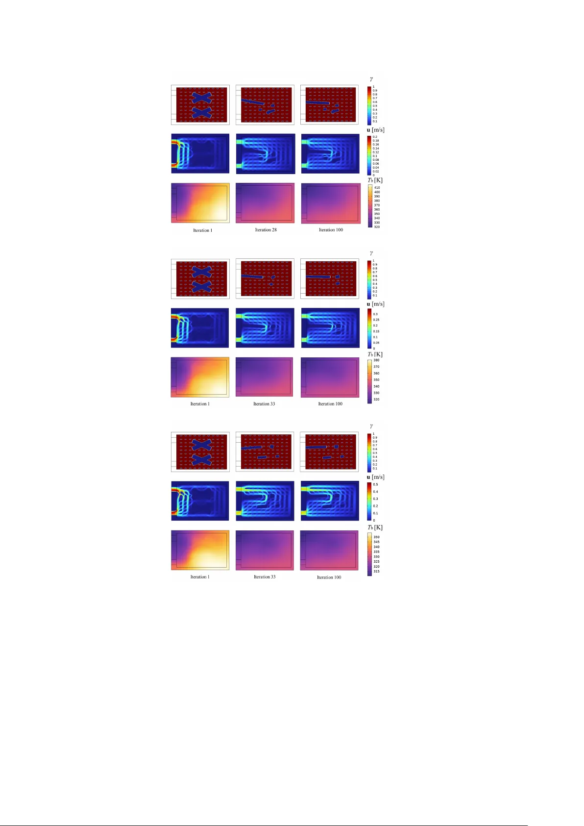
T op ology Optimization of Co oling Channels Using Dual-T yp e Mo ving Morphable Comp onen ts Sh unsuke Hirotani 1* , Kunitak a Shin tani 1 , Y oshik atsu F urusa wa 1 , Ken taro Y a ji 2 1 Nature Arc hitects Inc., 3-8, Nihon bashi-Ningyocho, Ch uo, T oky o, 103-0013, Japan. 2 The Univ ersity of Osak a, 2-1, Y amadaok a, Suita, Osak a, 565-0871, Japan. *Corresp onding author(s). E-mail(s): sh unsuke.hirotani@nature-arc hitects.com ; Con tributing authors: kunitak a@nature-arc hitects.com ; y oshik atsu.furusa wa@nature-arc hitects.com ; y a ji@mec h.eng.osak a-u.ac.jp ; Abstract Efficien t thermal management in high-pow er electronic devices requires co oling c hannel designs that provide high heat remo v al while satisfying strict spatial and man ufacturing constraints. This study presen ts a tw o-stage hierarc hical top ology optimization framework for co oling channels based on the Moving Morphable Comp onen ts (MMC) metho d. The optimization is p erformed sequen tially: in the first stage, only wall comp onents are optimized to establish the global flow net- w ork and insignifican t components are remov ed; in the second stage, the global structure is fixed and fin comp onen ts are optimized to improv e lo cal thermal p erformance. The metho d is coupled with a t wo-la yer thermofluid mo del using the Brinkman approximation and solved with the adj oin t sensitivity approach. Across multiple inlet pressure conditions, the prop osed framework consistently generates designs with clear functional separation. The results demonstrate that exploring suc h clearly separated structures through a tw o-stage optimization strategy leads to a further reduction in the ob jective function. Compared with sim ultaneous MMC optimization and conv entional density-based top ology opti- mization, the prop osed method pro duces geometries that are more interpretable, con trollable, and suitable for man ufacturing. 1 Keyw ords: T opology optimization; Mo ving morphable components; Thermal-fluid problem; Cooling channels 1 In tro duction In recent years, the imp ortance of thermal managemen t has increased significantly due to contin uous improv emen ts in energy efficiency and the adv ancing p erformance of electronic devices ( Dhumal et al. 2023 ). High-p o wer batteries for electric vehicles (EVs), p o wer electronic comp onen ts, and highly in tegrated semiconductor devices are particularly prone to rapid temp erature rises and hot-sp ot formation caused b y lo cally in tensified heat generation. Such temp erature excursions can degrade p erformance, reduce reliabilit y , and shorten operational lifetimes, p oten tially leading to catastrophic failure. Consequen tly , there is a strong demand for tec hnologies that enable the design of efficien t and reliable co oling structures under limited space and strict mechani- cal constraints. Among v arious co oling strategies, flo w-channel-based liquid co oling systems are widely employ ed, and their geometric design has b een recognized as a crit- ical issue in next-generation electronic thermal managemen t ( Garimella et al. 2008 ). These studies highlight the imp ortance of optimizing internal flow paths to enhance heat transfer while main taining acceptable pressure losses. Ho wev er, systematic design metho dologies that can efficiently explore the trade-off b et ween global flow control and local heat transfer enhancemen t remain an open c hallenge. Ov er the past several decades, significan t progress has b een made in the size and shap e optimization of fluid systems, exemplified b y the seminal w orks ( Moham- madi and Pironneau 2009 ). Ho wev er, these approaches are generally limited to optimizing pre-existing b oundaries and do not allo w for top ological c hanges dur- ing the optimization pro cess. T o ov ercome this limitation, top ology optimization has emerged as a p ow erful and flexible methodology ( Bendsøe and Kikuc hi 1988 ; Bendsøe 1989 ; Sethian and Wiegmann 2000 ). By treating the material distribution within a prescribed domain as the design v ariable, topology optimization enables the automatic generation of structures that optimize ob jectives such as pressure loss, thermal performance, or structural compliance. V arious form ulations hav e b een pro- p osed, including homogenization-based, density-based, and level-set metho ds, and ha ve b een successfully applied to structural mechanics, heat conduction, fluid flow, and coupled thermofluid problems. Bendsøe and Sigmund ( 2003 ) systematically estab- lished the theoretical and n umerical foundations of topology optimization, particularly for density-based metho ds, thereb y providing a basis for subsequent m ultiphysics extensions. T op ology optimization for fluid problems was initiated b y Borrv all and Petersson ( 2003 ), who addressed Stokes flow and introduced a framew ork for minimizing p o w er dissipation under a fluid volume constrain t. This framework was later extended to incompressible Na vier–Stok es flo ws b y Olesen et al. ( 2006 ). Subsequen t studies incor- p orated conv ectiv e heat transfer and conjugate thermofluid effects, including flo ws at higher Reynolds num b ers. F or example, early efforts in top ology optimization for 2 heat transfer-related design include the work by Y o on ( 2010 ), who applied topology optimization to heat-dissipating structures with forced conv ectiv e transp ort, demon- strating the imp ortance of balancing conduction and conv ection. Alexandersen et al. ( 2015 ) subsequently inv estigated top ology optimization for natural conv ection and sho wed the automatic generation of optimal heat sink geometries. Dilgen et al. ( 2018 ) extended topology optimization to practical high-Reynolds-n umber applications b y com bining turbulence mo deling with adjoin t sensitivity analysis. Y an et al. ( 2019 ) optimized solid–fluid bila y er and m ultila yer channel mo dels while accounting for both thermal performance and pressure loss, demonstrating the emergence of complex and non-in tuitive c hannel geometries. In addition, Alexandersen and Andreasen ( 2020 ) pro vided a comprehensive review of top ology optimization metho ds for fluid flo w and conjugate heat transfer problems, summarizing the state of the art and highlighting future researc h directions. These developmen ts highligh t the versatilit y and design freedom offered b y topology optimization in thermal managemen t. Despite these adv ances, top ology-optimized designs often insufficien tly accoun t for man ufacturing constrain ts and practical industrial requiremen ts. In densit y-based approac hes, geometric smo othness and minim um feature sizes can b e influenced using filtering and pro jection schemes; ho wev er, the explicit enforcement of constraints suc h as minimum channel widths, clearances, and curv ature radii remains challenging. In fluid-related top ology optimization, additional geometric requirements arise, includ- ing the need to ensure well-defined channel widths, suppress gra y transition regions b et w een solid and fluid, and maintain sufficient hydraulic diameters to av oid exces- siv e pressure losses. Recen t studies hav e also introduced geometry-control strategies tailored sp ecifically to flo w problems, suc h as density filters designed for pipe-like struc- tures to regulate uniform wall thickness and cross-sectional consistency within fluid domains ( Choi and Y o on 2024 ). T o address geometric length-scale issues more broadly , Guest et al. ( 2004 ) proposed tec hniques for length-scale con trol, while Sigmund ( 2007 ) in tro duced morphological filtering to obtain crisp and man ufacturable designs. Robust form ulations that accoun t for manufacturing v ariability were developed b y W ang et al. ( 2011 ) and Sc hevenels et al. ( 2011 ). With the rapid adv ancement of additive man- ufacturing, orientation-dependent constraints suc h as o verhang limitations hav e also b een incorp orated in to top ology optimization. Langelaar ( 2017 ) prop osed a filtering strategy tailored to additiv e manufacturing, and Allaire et al. ( 2017 ) established a theoretical framew ork for optimization under ov erhang constraints. Nevertheless, the complex geometries generated b y topology optimization often require extensiv e p ost- pro cessing, whic h can degrade p erformance and obscure the original design in tent. This situation underscores the need for optimization frameworks that inherently restrict the design space to manufacturable and geometrically well-defined solutions. The Moving Morphable Comp onen ts (MMC) approach, prop osed by Guo et al. ( 2014 ), offers a promising alternative for integrating design inten t with manufac- turing constraints. Unlike conv entional metho ds that implicitly represent material distribution, MMC emplo ys explicitly defined geometric comp onents whose p ositions, dimensions, and orien tations are treated as design v ariables. As a result, constraints suc h as minimum channel widths or manufacturable orientations can b e directly 3 imp osed through b ounds on comp onent parameters, providing clear and intuitiv e geometric con trollability . Sev eral comp onent-based top ology optimization metho ds, including MMC, rely on feature-mapping techniques to pro ject geometric information onto a fixed anal- ysis mesh. These approaches can b e broadly classified into combine-then-map and map-then-com bine strategies. MMC b elongs to the former category , in whic h indi- vidual top ology description functions (TDFs) are first aggregated and subsequently mapp ed to material properties. In contrast, the geometry pro jection method prop osed b y Norato et al. ( 2015 ) maps each component individually prior to combination. A comprehensiv e comparison of these paradigms is provided by W ein et al. ( 2020 ). The MMC framew ork has b een extended in several directions. Zhang et al. ( 2016 ) in tro duced tap ered comp onen ts with linearly v arying thic kness, while Guo et al. ( 2016a ) parameterized component centerlines using trigonometric functions to gener- ate p erio dic w avy structures. Deng and Chen ( 2016 ) incorporated join t-like constraints to explicitly mo del m ulti-link mec hanisms. More recently , Hirotani et al. ( 2025 ) pro- p osed a formulation based on cubic p olynomial interpolation of neutral axes, in which the position vectors and cross-sectional orien tation angles at both ends of eac h comp o- nen t are treated as design v ariables. This formulation ensures C 1 con tinuit y b et ween comp onen ts and enables the representation of complex curved geometries. These dev el- opmen ts demonstrate the high geometric expressiveness and flexibility of the MMC approac h. MMC has also b een applied to thermofluid design. Y u et al. ( 2019 ) introduced an MMC-based framework in whic h fluid domains are explicitly represented and optimized, with channel centerlines describ ed by p olynomial functions. Their results sho wed that highly sin uous and non-intuitiv e cooling channels can be generated while main taining explicit geometric con trol, thereby effectiv ely bridging the gap b etw een MMC and densit y-based approac hes. Ho wev er, existing MMC-based thermofluid mo dels exhibit notable limitations. In particular, p olynomial-based c hannel representations are not well suited for mo deling isolated solid features such as pin fins or baffles embedded within the flow. Because these formulations inherently assume contin uous flow paths, they cannot easily rep- resen t closed solid con tours. Moreov er, when a single comp onen t type is used to sim ultaneously define global flow routing and lo cal heat-transfer-promoting features, it b ecomes difficult to distinguish the roles of individual comp onents in system- lev el flow control and lo cal heat-transfer enhancement. This coupling complicates design interpretation, reduces robustness, and makes p ost-optimization refinement difficult. In addition, fine-scale features that also determine global flo w paths can ren- der system-level p erformance highly sensitive to lo cal degradation or manufacturing tolerances. T o address these challenges, prior studies in top ology optimization hav e explored hierarc hical and multiscale design strategies, including staged optimization ( Ro drigues et al. 2002 ; Xia and Breitk opf 2014 ), multiresolution metho ds ( Nguyen et al. 2010 ), and t wo-scale optimization frameworks that explicitly account for man ufacturability ( Sc hury et al. 2012 ). Although these approac hes are not specific to MMC form ulations, they highligh t the importance of separating global and lo cal design roles. 4 Motiv ated by these considerations, the present study prop oses a tw o-stage hier- arc hical MMC-based optimization framew ork that explicitly separates global flow- c hannel design from lo cal heat-transfer enhancement. Unlike conv entional staged or m ultiscale approaches, the prop osed framework introduces tw o distinct comp onen t t yp es within the MMC formulation: wall comp onen ts, which define the global flo w- c hannel sk eleton, and fin comp onen ts, which are em b edded within the channels to lo cally enhance heat transfer. In the first stage, the global channel lay out is optimized using wall components. In the second stage, with the global structure fixed, fin com- p onen ts are optimized to regulate local thermal p erformance. This clear separation of design scales enables the generation of robust and controllable cooling channel designs that inheren tly satisfy man ufacturing constrain ts. The remainder of this pap er is organized as follo ws. Section 2 describ es the ther- mofluid mo del and the proposed MMC-based optimization framew ork. Section 3 presen ts numerical examples under v arious design conditions and compares the results with existing metho ds. Finally , Section 4 concludes the pap er and discusses future c hallenges and researc h directions. 2 Optimization F ramew ork 2.1 Prop osed Optimization F ramework The proposed optimization framework is describ ed. In this study , t wo t ypes of MMC comp onen ts with distinct functions are introduced: rectangular wall comp onen ts that can freely mov e within the design domain, and elliptical fin comp onen ts whose p osi- tions are fixed. Using these comp onen ts, the optimization of the co oling channel is carried out through a tw o-stage hierarchical pro cedure. A conceptual diagram of the prop osed optimization framework is shown in Fig. 1 . The optimization is p erformed according to the following steps. Fig. 1 Conceptual diagram of the prop osed optimization framework. 5 Step 1. W all comp onen ts and fin comp onen ts are initially placed within the design domain. Step 2. The global flow-c hannel netw ork is optimized using only the wall comp onen ts as design v ariables. Step 3. Among the resulting wall comp onen ts, those with sizes below a prescrib ed threshold that do not contribute to the formation of the global flow channels are remo ved. Step 4. F or the remaining wall comp onen ts, fin comp onen ts that are lo cated closer than a predefined threshold distance are remov ed, lea ving only candidate fin comp onen ts for the second-stage optimization. Step 5. The local heat transfer c haracteristics within the channels are optimized using only the fin comp onents as design v ariables. Step 6. Finally , fin components with sizes b elo w a prescrib ed threshold are remov ed, and the resulting structure is adopted as the final design. The primary adv antages of separating the optimization in to tw o stages can b e summarized as follo ws: (i) clear separation of functional roles across global and local spatial scales, (ii) improv ed n umerical stability and computational efficiency b y progressiv ely reducing the design space, and (iii) generation of final designs that are physically interpretable and readily man ufac- turable. First, in the proposed framew ork, wall comp onents are exclusively responsible for forming the global flow-c hannel net work, whereas fin components are dedicated to con trolling lo cal heat transfer within the already established channels. By separating functions and spatial scales at the comp onen t level, the roles of design freedoms are clearly defined. As a result, if one wishes to mo dify global design features such as c hannel routing or branching lo cations, only the parameters of the wall comp onen ts need to b e adjusted. Con versely , if lo cal heat transfer p erformance is to b e tuned, only the dimensions or orientation s of the fin comp onents need to b e mo dified. This separation enables localized and systematic post-optimization design modifications. Second, the t wo-stage form ulation impro ves numerical stability and efficiency by a voiding the sim ultaneous exploration of a strongly coupled, high-dimensional design space. In the first stage, the global c hannel net work is formed using only w all compo- nen ts, and w all comp onen ts b elo w a size threshold that do not con tribute to global c hannel formation are remo ved early in the pro cess. Moreov er, by remo ving fin can- didates that are closer than a prescribed threshold to the finalized w alls, the n umber of fin comp onen ts considered in the second stage is further reduced. As a result, the second-stage optimization deals only with lo cal structures under a fixed global lay out, leading to a low er-dimensional and more w eakly coupled optimization problem. Third, the com bination of tw o-stage optimization and threshold-based component remo v al improv es b oth the physical interpretabilit y and man ufacturability of the final design. F or b oth walls and fins, geometrically insignificant features b elo w prescrib ed 6 thresholds are systematically remov ed, eliminating nonessential microstructures. Con- sequen tly , the remaining wall comp onen ts clearly define the channel sk eleton, while the fin comp onents are sp ecialized for local heat transfer con trol within that skeleton. 2.2 Thermofluid Mo del In this study , the tw o-la yer thermofluid mo del is adopted, consisting of an upp er thermofluid la yer and a lo w er substrate la yer ( Y an et al. 2019 ). In the tw o-lay er mo del, the upp er lay er treats b oth fluid and solid regions using a contin uous density field γ ( x, y ) ∈ [0 , 1] based on the Brinkman appro ximation, where the v elo cit y in the solid region is suppressed through inv erse permeability α ( γ ). The analysis is p erformed on a tw o-dimensional domain by solving the gov erning equations for fluid flo w and heat transfer. F or the upp er fluid la yer, assuming incompressible flow, the con tinuit y equation is giv en by ∇ · u = 0 , (1) where u denotes the velocity field. The momentum conserv ation equation based on the Brinkman appro ximation is expressed as 6 7 ρ ( u · ∇ ) u = −∇ p + µ ∇ · ∇ u + ( ∇ u ) T − α ( γ ) u , (2) where ρ is the fluid density , p is the pressure and µ is the fluid dynamic viscosity . The energy conserv ation equation for the upp er la y er is derived based on the t wo- la yer mo del that assumes sp ecific velocity and temp erature profiles across the channel heigh t, and is written as 2 3 ρC p u · ∇ T t − 49 52 ∇ · k t ( γ ) ∇ T t − h ( γ ) 2 H t ( γ ) ( T b − T t ) = 0 , (3) where C p is the sp ecific heat capacity of the fluid, k t ( γ ) is the effective thermal con- ductivit y of the upp er la yer, h ( γ ) is the interfacial heat transfer co efficien t b etw een the t wo lay ers, H t ( γ ) is the effectiv e thic kness of the upp er la yer, and T t and T b denote the represen tative temp eratures of the upp er and lo wer lay ers, resp ectiv ely . F or the low er substrate lay er, assuming a linear temp erature distribution across the thickness direction, a tw o-dimensional heat conduction equation is form ulated for the in-plane represen tativ e temp erature T b as k b 2 ∇ 2 T b + h ( γ ) 2 H b ( T b − T t ) + q ′′ 0 2 H b = 0 , (4) where k b is the thermal conductivit y of the substrate material, H b is the half-thic kness of the substrate, and q ′′ 0 is the uniform heat flux applied from the b ottom surface of the substrate. The second term represents the out-of-plane interfacial heat flux b et ween the tw o lay ers, q int = h ( γ ) ( T b − T t ) . Through Eqs. ( 3 ) and ( 4 ), the con vectiv e– conductiv e heat transfer in the upp er lay er and the conductive heat transfer in the 7 lo wer la y er are thermally coupled, forming the t wo-la yer thermofluid model. By solv- ing the go verning equations ( 1 )–( 4 ) together with the inlet and outlet pressure and temp erature conditions and the v elo cit y and temperature b oundary conditions on the outer w alls, the thermofluid fields of the cooling c hannel structures considered in this study are ev aluated. The material distribution γ ( x, y ) is incorp orated into these gov erning equations through effective material prop erties suc h as α ( γ ) and k t ( γ ). T o smoothly and non- linearly in terp olate b et ween the material prop erties of the fluid region ( γ = 1) and the solid region ( γ = 0), the Rational Approximation of Material Prop erties (RAMP) sc heme is employ ed ( Alexandersen 2023 ). Sp ecifically , the Brinkman resistance co ef- ficien t α ( γ ) is interpolated using a low resistance v alue α f for the fluid phase and a high resistance v alue α s for the solid phase as α ( γ ) = α f + ( α s − α f ) 1 − γ 1 + q f γ , (5) where q f > 0 is a parameter controlling the sensitivity of the interpolation with resp ect to changes in the design v ariable. Similarly , the effective thermal conductivity of the upp er lay er k t ( γ ) is interpolated from the fluid thermal conductivit y k f and the solid thermal conductivit y k s as k t ( γ ) = k f + ( k s − k f ) 1 − γ 1 + q k γ , (6) where q k > 0 controls the slop e of the interpolation. 2.3 F ormulation 2.3.1 Design V ariables of Individual Comp onen ts In this study , tw o types of MMC comp onents are introduced to represen t the co oling c hannel geometry: rectangular wall comp onen ts that can freely mo ve within the design domain, and elliptical fin components whose p ositions are fixed, as illustrated in Fig. 2 . The wall comp onen ts are in tro duced to form the global netw ork and skeleton of the flow c hannels. Their design v ariables consist of the center co ordinates ( X 0 , Y 0 ), the length in the longitudinal direction L , the thickness in the transverse direction t , and the rotation angle θ . In con trast, the fin components are in tro duced primarily to con trol the local heat transfer characteristics within the already established flow channels. In this study , the cen ter co ordinates ( X f , Y f ) of the fin comp onen ts are fixed a priori. Consequently , the design v ariables of each fin comp onen t are defined as the semi-ma jor axis length a , the ratio b et ween the semi-minor and semi-ma jor axes 0 ≤ k ≤ 1 (i.e., the semi-minor axis is giv en b y b = k a ), and the rotation angle ψ of the ellipse. 2.3.2 T op ology Description F unctions and Pro jection F unctions The geom etric shap e of eac h MMC component is represen ted using a T op ology Description F unction (TDF), which v aries smo othly with resp ect to the design 8 Fig. 2 W all comp onen ts and fin comp onen ts used in the optimization. v ariables ( Zhang et al. 2016 ). T o simplify the notation, let ∆ X w = X − X 0 , ∆ Y w = Y − Y 0 , (7) ∆ X f = X − X f , ∆ Y f = Y − Y f . (8) W e further define the local coordinates of the w all comp onen t as s w = ∆ X w cos θ + ∆ Y w sin θ, (9) n w = − ∆ X w sin θ + ∆ Y w cos θ, (10) and those of the fin comp onen t as s f = ∆ X f cos ψ + ∆ Y f sin ψ , (11) n f = − ∆ X f sin ψ + ∆ Y f cos ψ . (12) Using these local co ordinates, the TDF for a w all component is written as ϕ w ( X, Y ) = 1 − s w L 6 − n w t 6 , (13) whereas the TDF for a fin component is written as ϕ f ( X, Y ) = 1 − s f a 2 − n f k a 2 . (14) In b oth cases, the TDF is constructed as a scalar field that tak es p ositiv e v alues inside the comp onent and negative v alues outside, with the zero lev el set represen ting the component boundary . Ho wev er, in the Brinkman-based unified field form ulation adopted in the tw o- la yer thermofluid mo del, the presence of fluid and solid phases is represen ted by a con tinuous densit y v ariable ranging betw een 0 and 1. In contrast, the TDF tak es v alues 9 in the range ( −∞ , +1) and therefore cannot b e directly used as a material distribution v ariable. T o address this issue, the TDF is pro jected onto an approximately binary function using a hyperb olic tangent mapping. Specifically , the pro jected TDFs are defined as ˜ ϕ w ( X, Y ) = 1 2 ( 1 − tanh ( β ϕ w ( X, Y ) )) , (15) ˜ ϕ f ( X, Y ) = 1 2 ( 1 − tanh ( β ϕ f ( X, Y ) )) , (16) where β is a parameter that controls the sharpness of the transition near the comp onen t boundaries. Using these pro jected TDFs, the material distribution field γ ( X, Y ) is defined as γ ( X , Y ) = ˜ ϕ w ( X, Y ) ˜ ϕ f ( X, Y ) . (17) The resulting material distribution γ is then used in the in terp olation of the Brinkman resistance term α ( γ ) and the effective thermo-physical prop erties in the gov erning equations. 2.4 Optimization F orm ulation and Numerical Implemen tation 2.4.1 Optimization Problem In this study , the optimization ob jective is to minimize the normalized p -mean of the temp erature in the solid lay er (low er lay er). Let Ω b denote the low er-la yer domain and T b ( X, Y ) the temp erature field in the low er la yer. The ob jective function J is defined as J = 1 | Ω b | Z Ω b T b ( X, Y ) p dΩ 1 /p . (18) Here, p is an exponent used to approximate the maxim um temperature, with p → ∞ corresp onding to max( T b ). In this study , p = 10 is used ( Pejman et al. 2021 ). As constraints, upper and lo wer bounds are imp osed on the geometric parameters of the MMC components. The optimization is carried out according to the tw o-stage pro cedure describ ed in Section 2.1. 2.4.2 Numerical Implementation The following describ es the numerical implementation details of the prop osed opti- mization. The implementation is based on a finite elemen t discretization of the t wo-la yer thermofluid mo del together with adjoint sensitivities. In the unified Brinkman-type formulation, the material distribution field γ ( x ), defined from the pro jected top ology description functions, is ev aluated at the finite elemen t lev el. The Brinkman resistance α ( γ ) and effectiv e thermal conductivity k t ( γ ) are then computed via the RAMP interpolation. This element-wise representation allo ws the flo w and heat-transfer equations to b e assembled and solv ed on a fixed mesh without remeshing during the optimization. The velocity , pressure, and temp erature fields are discretized using first-order Lagrange finite elements. T o ensure n umerical stabilit y , streamline-upwind/P etro v– Galerkin (SUPG) stabilization is applied to the go verning equations in the thermofluid 10 la yer, including the Na vier–Stokes and energy equations. The stationary thermofluid solution is computed at eac h design iteration, and adjoint problems asso ciated with the ob jectiv e functional are solved to ev aluate gradients with respect to the comp onen t design v ariables. Design up dates are p erformed using the Metho d of Mo ving Asymptotes (MMA) ( Sv anberg 1987 ). Eac h optimization iteration consists of a stationary state solv e, adjoin t sensitivit y ev aluation, and an MMA update of the design v ariables considered in each stage. The optimization pro cess is terminated when the maximum normalized c hange in the design v ariables during one iteration b ecomes smaller than 10 − 3 . In the presen t study , the w orkflow is implemen ted in COMSOL Multiphysics, using the sta- tionary solver for the state analysis and the Optimization interface for adjoin t-based sensitivities. 3 Numerical Examples 3.1 Numerical Mo del In this section, n umerical examples of co oling channel optimization using the prop osed metho d are presen ted. The design domain is a rectangular region with an inlet lo cated at the upper left and an outlet at the low er left, as sho wn in Fig. 3 . A t the inlet, the pressure and temp erature are prescrib ed as constant v alues ( p = p in , T = 303 K), while zero pressure is imp osed at the outlet. No-slip conditions are applied on all w all b oundaries, and adiabatic b oundary conditions are imp osed on the outer walls of the design domain. The mo del assumes a cooling plate attached to a heat-generating device, and a uniform heat flux of q ′′ = 100 kW / m 2 is applied to the b ottom surface of the substrate. W ater and silicon are used as the fluid and solid materials, resp ectively . The ph ysical prop erties employ ed in the sim ulations are summarized in T able 1 . Fig. 3 Geometry mo del and boundary conditions for the tw o-dimensional cooling device. 11 T able 1 Material prop erties Parameters V alues Units W ater viscosity 0.001 Pa · s W ater heat capacity 4180 J/(kg · K) Silicon heat capacity 942 J/(kg · K) W ater conductivity 0.598 W/(m · K) Silicon conductivity 149 W/(m · K) 3.2 Results of the Tw o-Stage Optimization at Differen t Inlet Pressures First, the optimization results for the wall comp onen ts are presen ted for inlet pressures of p in = 50 , 100 , and 200 Pa. The material distribution, v elo cit y field, and solid-la yer temp erature distribution during the w all-optimization process are shown in Fig. 4 for (a) p in = 50 P a, (b) p in = 100 P a, and (c) p in = 200 P a. The corresp onding histories of the ob jectiv e function are shown in Fig. 5 . F or all inlet pressures considered, the wall-component optimization suppresses the direct flo w path from the inlet to the outlet and forms a c hannel that routes the flow around the righ t-hand side of the design domain, leading to a reduction in the ob jective function. Moreo ver, the solutions obtained after 100 iterations are almost identical to those obtained when the stopping criterion is satisfied, indicating that sufficien t con vergence is ac hieved b efore termination. Next, the optimization results for the fin comp onents are presented. Figure 6 sho ws the material distribution, velocity field, and solid-la yer temp erature distribution during fin optimization for (a) p in = 50 P a, (b) p in = 100 P a, and (c) p in = 200 P a. Figure 7 shows the corresp onding histories of the ob jective function. The initial design for fin optimization is obtained b y removing small wall comp onen ts from the w all-optimization result. In this study , w all components with lengths smaller than 20% of the longitudinal dimension of the design domain are remov ed. At all inlet pressures, the fin components effectively regulate lo cal flow patterns, yielding further reductions in the ob jective function. It is also observed that fins tend to b e more sparsely dis- tributed as the inlet pressure decreases. This trend can b e interpreted as follo ws. At higher inlet pressures, con vection is stronger and the flow velocities are higher; there- fore, flow curv ature and recirculation induced by fins enhance mixing and promote thermal-b oundary-la y er thinning, whic h increases heat transfer. At low er inlet pres- sures, the flow b ecomes relativ ely weak er and more diffusion-dominated; in this regime, the conv ectiv e con tribution is limited while the additional flow resistance introduced b y fins be comes more influential, making dense fin distributions less beneficial. T o further assess conv ergence and coupling b et ween stages, the fin-optimization result is fed back into the wall optimization. Figure 8 shows the material distribu- tion obtained when the wall components are optimized again at an inlet pressure of 200 P a. The material distribution remains almost unchanged, indicating that the w all- comp onen t optim um is largely insensitiv e to the fin-optimization outcome and that the t wo-stage pro cedure is stable. 12 (a) (b) (c) Fig. 4 Results at each inlet pressure during wall optimization: (a) p in = 50 Pa, (b) p in = 100 Pa, (c) p in = 200 P a. The top row shows the material distribution, the middle row shows the flo w velocity distribution, and the b ottom row shows the temperature distribution of the solid lay er. 13 Fig. 5 Ob jectiv e function histories during wall-component optimization for multiple inlet pressure conditions. 3.3 Comparison Betw een Sim ultaneous Optimization and Tw o-Stage Optimization Next, the results of simultaneous optimization, in which wall and fin comp onen ts are optimized concurrently , are compared with those obtained using the prop osed tw o- stage optimization framework. The result of the simultaneous optimization at an inlet pressure of 200 Pa is shown in Fig. 9 . F rom the material distribution in Fig. 9 , it can b e observed that the tw o comp o- nen t types no longer maintain a clear division of functional roles in the sim ultaneous optimization. Sp ecifically , wall comp onen ts are partly used for lo cal heat-transfer enhancemen t (originally the role of fins), while fin comp onen ts contribute to forming the global flow-c hannel netw ork. Consequently , the separation b et w een global chan- nel formation and lo cal heat-transfer enhancement becomes unclear. In contrast, the prop osed metho d determines the global flo w-c hannel sk eleton using only wall comp o- nen ts in the first stage, and then optimizes only fin comp onents within the established c hannels in the second stage. This staged pro cess preserves clear functional separation and progressively reduces the design space. A comparison of the ob jective-function histories is presented in Fig. 10 . F rom Fig. 10 , the prop osed tw o-stage optimization ac hieves a lo wer final ob jective-function v alue. Although the simultaneous optimiza- tion reduces the ob jective function more rapidly in the early iterations b ecause both w all and fin v ariables are up dated simultaneously , it ev en tually conv erges to a higher lo cal minimum than the tw o-stage approac h. 14 (a) (b) (c) Fig. 6 Results at each inlet pressure during fin optimization: (a) p in = 50 Pa, (b) p in = 100 Pa, (c) p in = 200 P a. The top row shows the material distribution, the middle row shows the flo w velocity distribution, and the b ottom row shows the temperature distribution of the solid lay er. 15 Fig. 7 Ob jectiv e function histories during fin-component optimization for multiple inlet pressure conditions. Fig. 8 Optimization pro cess when wall comp onents are re-optimized. 3.4 Comparison with Densit y-Based T op ology Optimization Finally , the proposed tw o-stage optimization framework is compared with conv entional densit y-based top ology optimization. The result of the densit y-based top ology opti- mization at an inlet pressure of 200 P a is sho wn in Fig. 11 , whereas Fig. 12 presents the comparison of the corresp onding ob jectiv e-function histories. F rom the material distribution in Fig. 11 , it can b e observed that densit y-based top ology optimization treats the design as a pixel-wise con tin uous field. This pro vides extremely high geometric freedom and often yields complex and non-intuitiv e channel geometries. In contrast, the prop osed MMC-based approach represents the geome- try using explicit comp onen t parameters, resulting in designs with clearer physical in terpretation and higher compatibilit y with CAD-based redesign and reuse. 16 Fig. 9 Sim ultaneous optimization pro cess of wall and fin comp onen ts. Fig. 10 Comparison of ob jective function histories b et ween the tw o-stage optimization and the simultaneous optimization. F rom Fig. 12 , the prop osed tw o-stage optimization conv erges more rapidly and ac hieves a low er final ob jective-function v alue. These results demonstrate that the prop osed metho d can attain performance comparable to or b etter than density- based top ology optimization while main taining superior geometric controllabilit y and practical man ufacturability . 17 Fig. 11 Result of density-based topology optimization. Fig. 12 Comparison of ob jective function histories between the t wo-stage optimization and density- based top ology optimization. 4 Conclusion In this study , a hierarchical MMC-based topology optimization framework w as pro- p osed for the design of co oling channel systems, in which wall and fin components are optimized in t wo successiv e stages. Rectangular wall components are first introduced to establish the global sk eleton of the flow-c hannel netw ork, and elliptical fin compo- nen ts are subsequen tly optimized within this predefined sk eleton to regulate lo cal heat transfer. By explicitly separating global flo w-c hannel formation and local heat transfer enhancemen t across different spatial scales, the prop osed strategy ac hieves a struc- tured decomp osition of the design space and clarifies the physical roles of individual comp onen ts. 18 Numerical inv estigations under inlet pressures of 50, 100, and 200 Pa demonstrate that the proposed approach consistently generates cooling c hannel configurations with a clear functional allocation: wall comp onents predominantly determine the global flo w top ology , while fin comp onen ts enhance lo cal mixing and heat transfer. It is fur- ther observed that the optimal fin density decreases as the inlet pressure is reduced. This tendency reflects the shift in the trade-off b et ween pressure loss and heat trans- fer enhancemen t: under low-flo w conditions, the additional flow resistance induced b y fins b ecomes comparatively more influential, leading the optimization pro cess to suppress excessive fin insertion. These results confirm that the proposed method cap- tures ph ysically consisten t design tendencies rather than merely pro ducing n umerical artifacts. Compared with density-based top ology optimization, the tw o-stage MMC frame- w ork inv olv es a low er degree of geometric freedom due to its explicit comp onen t parameterization. Nevertheless, the resulting channel geometries exhibit simpler and more in terpretable structural patterns that directly corresp ond to meaningful geo- metric parameters. F rom an optimization p ersp ectiv e, the hierarchical separation effectiv ely regularizes the design space by reducing strong cross-couplings b etw een global and local design v ariables. Despite the reduced geometric freedom, the ob jec- tiv e function defined by the p -mean temperature of the solid lay er decrease s more rapidly during optimization and con verges to low er final v alues than those obtained b y density-based metho ds. This indicates that an appropriately structured represen- tation can enhance b oth numerical stability and physical effectiveness without relying on excessiv e geometric complexit y . In contrast, when wall and fin comp onen ts are optimized simultaneously , their structural roles tend to ov erlap and compete within a strongly coupled design space. Suc h coupling obscures the distinction b et ween global flow formation and lo cal heat transfer mec hanisms, and leads to less effective ob jectiv e reduction. The results therefore highlight the imp ortance of hierarchically decomp osing multi-scale design problems to improv e sensitivit y conditioning and to balance comp eting physical effects in thermofluid optimization. A central adv antage of the MMC framework lies in its flexibility to tailor com- p onen t shap e descriptions and design-v ariable relationships according to sp ecific functional and manufacturing requirements. Although the present study fo cuses on w all and fin comp onen ts, the metho dology can b e systematically extended to incorp o- rate additional comp onen t t yp es that enforce geometric constraints, man ufacturability considerations, or prescribed connectivit y conditions. F uture work will extend the prop osed approac h to higher Reynolds num b er regimes, transient thermal loading, and fully three-dimensional form ulations. F ur- thermore, the direct em b edding of realistic man ufacturing constraints in to MMC comp onen t definitions, as well as extensions to m ulti-ob jective and robust optimization settings, will further enhance its practical applicabilit y . Through these developmen ts, hierarc hical component-based top ology optimization has the p oten tial to pro vide a ph ysically interpretable and practically implemen table framework for adv anced cooling c hannel design. 19 Declarations F unding The authors receiv ed no external funding for this study . Conflict of in terest On b ehalf of all authors, the corresp onding author states that there is no conflict of in terest. Author contributions Sh unsuke Hirotani: Conceptualization, Metho dology , Soft w are, F ormal analysis, In ves- tigation, Visualization, W riting–original draft. Kunitak a Shin tani: Methodology , Sup ervision, W riting–review and editing. Y oshik atsu F urusaw a: V alidation, W riting– review and editing. Kentaro Y a ji: Metho dology , Sup ervision, W riting–review and editing. Data av ailabilit y The data generated and/or analyzed during the current study are a v ailable from the corresp onding author on reasonable request. Co de av ailabilit y The code and computational mo del used in the curren t study , including the COMSOL Multiph ysics setup and optimization w orkflow, are a v ailable from the corresp onding author on reasonable request. Replication of results The results presen ted in this paper can b e repro duced based on the numerical mo del, optimization form ulation, and implementation details describ ed in Sections 2 and 3. In particular, the gov erning equations, material in terp olation sc heme, MMC parame- terization, optimization procedure, and b oundary conditions are pro vided to supp ort repro ducibilit y . The data, co de, and computational mo del used in this study are a v ailable from the corresponding author on reasonable request. References Alexandersen J, Aage N, Andreasen CS, Sigmund O (2015) T op ology optimisation for natural conv ection problems. Int J Numer Metho ds Fluids 76(10):699–721. ht tps : //doi.org/10.1002/fld.3954 Alexandersen J, Andreasen CS (2020) A review of top ology optimisation for fluid- based problems. Fluids 5(1):29. https://doi.org/10.3390/fluids5010029 20 Alexandersen J (2023) A detailed in troduction to density-based topology optimisation of fluid flo w problems with implementation in MA TLAB. Struct Multidisc Optim 66(1):12. h ttps://doi.org/10.1007/s00158- 022- 03420- 9 Allaire G, Dap ogny C, Estevez R, F aure A, Mic hailidis G (2017) Structural optimiza- tion under o verhang constraints imp osed by additive manufacturing technologies. J Comput Ph ys 351:295–328. h ttps://doi.org/10.1016/j.jcp.2017.09.041 Bendsøe MP (1989) Optimal shape design as a material distribution problem. Struct Optim 1(4):193–202. h ttps://doi.org/10.1007/BF01650949 Bendsøe MP , Kikuc hi N (1988) Generating optimal top ologies in structural design using a homogenization metho d. Comput Metho ds Appl Mec h Eng 71(2):197–224. h ttps://doi.org/10.1016/0045- 7825(88)90086- 2 Bendsøe MP , Sigm und O (2003) T op ology Optimization: Theory , Metho ds, and Appli- cations. Springer, Berlin Heidelb erg. h t tp s : / / d o i . o r g / 10 . 1 0 0 7 / 9 7 8- 3 - 6 6 2 - 0 5 0 8 6 - 6 Borrv all T, P etersson J (2003) T op ology optimization of fluids in Stok es flo w. Int J Numer Methods Fluids 41:77–107. h ttps://doi.org/10.1002/fld.426 Choi YH, Y o on GH (2024) A new densit y filter for pip es for fluid topology optimization. J Fluid Mech 986:A9. https://doi.org/10.1017/jf m.2024.170 Deng J, Chen W (2016) Design for structural flexibility using connected morphable comp onen ts based top ology optimization. Sci China T echnol Sci 59:839–851. https: //doi.org/10.1007/s11431- 016- 6027- 0 Dh umal AR, Kulk arni AP , Ambhore NH (2023) A comprehensive review on thermal managemen t of electronic devices. J Eng Appl Sci 70:140. h ttps://doi.org/10.1186/ s44147- 023- 00309- 2 Dilgen CB, Dilgen SB, F uhrman DR, Sigmund O, Lazarov BS (2018) T op ology optimization of turbulen t flows. Comput Metho ds Appl Mech Eng 331:363–393. h ttps://doi.org/10.1016/j.cma.2017.11.029 Garimella SV, Fleischer AS, Murthy JY, Keshav arzi A, Prasher R, Patel C, Bhav- nani SH, V enk atasubramanian R, Maha jan R, Joshi Y, Sammakia B, My ers BA, Chorosinski L, Baelmans M, Sath y amurth y P , Raad PE (2008) Thermal c hallenges in next-generation electronic systems. IEEE T rans Comp onen ts Pac k ag T echnol 31(4):801–815. h ttps://doi.org/10.1109/TCAPT.2008.2001197 Guest JK, Pr´ ev ost JH, Belytschk o T (2004) Achieving minim um length scale in top ol- ogy optimization using no dal design v ariables and pro jection functions. Int J Numer Metho ds Eng 61(2):238–254. https://doi.org/10.1002/nme.1064 21 Guo X, Zhang W, Zhang J, Y uan J (2016) Explicit structural top ology optimization based on moving morphable comp onen ts (MMC) with curved skeletons. Comput Metho ds Appl Mech Eng 310:711–748. https://doi.org/10.1016/j.cma.2016.07.018 Guo X, Zhang W, Zhong W (2014) Doing topology optimization explicitly and geometrically—A new moving morphable comp onen ts based framework. J Appl Mec h 81(8):081009. h ttps://doi.org/10.1115/1.4027609 Hirotani S, Y a ji K, Makihara K, Otsuk a K (2025) Data-Driven Real-Time T op ology Optimization Using Consistent Rotation-Based Moving Morphable Comp onen ts. AIAA J 63(10):4491–4497. https://doi.org/10.2514/1.J065458 Langelaar M (2017) An additive man ufacturing filter for top ology optimization of prin t-ready designs. Struct Multidisc Optim 55:871–883. https ://d oi.or g/10. 1007 / s00158- 016- 1522- 2 Mohammadi B, Pironneau O (2009) Applied shap e optimization for fluids. Oxford Univ ersity Press, Oxford. https://academic.oup.com/book/1641 Nguy en TH, Paulino GH, Song J, Le CH (2010) A computational paradigm for mul- tiresolution top ology optimization (MTOP). Struct Multidisc Optim 41:525–539. h ttps://doi.org/10.1007/s00158- 009- 0443- 8 Norato JA, Bell BK, T ortorelli D A (2015) A geometry pro jection metho d for con tinuum-based topology optimization with discrete elements. Comput Metho ds Appl Mec h Eng 293:306–327. h ttps://doi.org/10.1016/j.cma.2015.05.005 Olesen LH, Okkels F, Bruus H (2006) A high-lev el programming-language implemen- tation of top ology optimization applied to steady-state Na vier–Stokes flow. In t J Numer Methods Eng 65:975–1001. h ttps://doi.org/10.1002/nme.1468 P ejman R, Sigm und O, Na jafi AR (2021) T op ology optimization of microv ascular comp osites for active-cooling applications using a geometrical reduced-order mo del. Struct Multidiscip Optim 64:563–583. https://doi.org/10.1007/s00158- 021- 02951- x Ro drigues H, Guedes JM, Bendsøe MP (2002) Hierarchical optimization of material and structure. Struct Multidisc Optim 24(1):1–10. https://doi.o rg/10.1007/s0 0158 - 002- 0209- z Sc hevenels M, Lazarov BS, Sigmund O (2011) Robust top ology optimization accoun t- ing for spatially v arying man ufacturing errors. Comput Metho ds Appl Mech Eng 200(49–52):3613–3627. h ttps://doi.org/10.1016/j.cma.2011.08.006 Sc hury F, Stingl M, W ein F (2012) Efficien t tw o-scale optimization of man ufacturable graded structures. SIAM J Sci Comput 34(6):B711–B733. https://doi.org/10.1137/ 110850335 22 Sethian JA, Wiegmann A (2000) Structural b oundary design via level set and immersed in terface metho ds. J Comput Phys 163(2):489–528. h ttps:// doi.org/10.1 006/jcph.2000.6581 Sigm und O (2007) Morphology-based blac k and white filters for topology optimization. Struct Multidisc Optim 33:401–424. https://doi.org/10.1007/s00158- 006- 0087- x Sv anberg K (1987) The metho d of mo ving asymptotes—a new metho d for structural optimization. Int J Numer Methods Eng 24(2):359–373. http s:/ /do i.o rg/ 10. 10 02/ nme.1620240207 W ang F, Lazarov BS, Sigm und O (2011) On pro jection metho ds, conv ergence and robust formulations in top ology optimization. Struct Multidisc Optim 43:767–784. h ttps://doi.org/10.1007/s00158- 010- 0602- y W ein F, Dunning PD, Norato JA (2020) A review on feature-mapping metho ds for structural optimization. Struct Multidisc Optim 62(4):1597–1638. https://doi.or g/ 10.1007/s00158- 020- 02649- 6 Xia L, Breitk opf P (2014) Concurrent top ology optimization design of material and structure within FE 2 nonlinear multiscale analysis framework. Comput Metho ds Appl Mec h Eng 278:524–542. h ttps://doi.org/10.1016/j.cma.2014.05.022 Y an S, W ang F, Hong J, Sigm und O (2019) T op ology optimization of micro c hannel heat sinks using a tw o-la yer mo del. Int J Heat Mass T ransfer 143:118462. ht t ps : //doi.org/10.1016/j.ijheatmasstransf er.2019.118462 Y o on GH (2010) T op ological design of heat dissipating structure with forced con vectiv e heat transfer. J Mech Sci T echnol 24(6):1225–1233. https://doi.org/10.1007/s12206 - 010- 0328- 1 Y u M, Ruan S, W ang X, Li Z, Shen C (2019) T op ology optimization of thermal– fluid problem using the MMC-based approach. Struct Multidisc Optim 60:151–165. h ttps://doi.org/10.1007/s00158- 019- 02206- w Zhang W, Y uan J, Zhang J, Guo X (2016) A new top ology optimization approach based on Mo ving Morphable Comp onen ts (MMC) and the ersatz material mo del. Struct Multidisc Optim 53:1243–1260. https://doi.org/10.1007/s00158- 015- 1372- 3 23
Original Paper
Loading high-quality paper...
Comments & Academic Discussion
Loading comments...
Leave a Comment