Expert Streaming: Accelerating Low-Batch MoE Inference via Multi-chiplet Architecture and Dynamic Expert Trajectory Scheduling
Mixture-of-Experts is a promising approach for edge AI with low-batch inference. Yet, on-device deployments often face limited on-chip memory and severe workload imbalance; the prevalent use of offloading further incurs off-chip memory access bottlen…
Authors: Songchen Ma, Hongyi Li, Weihao Zhang
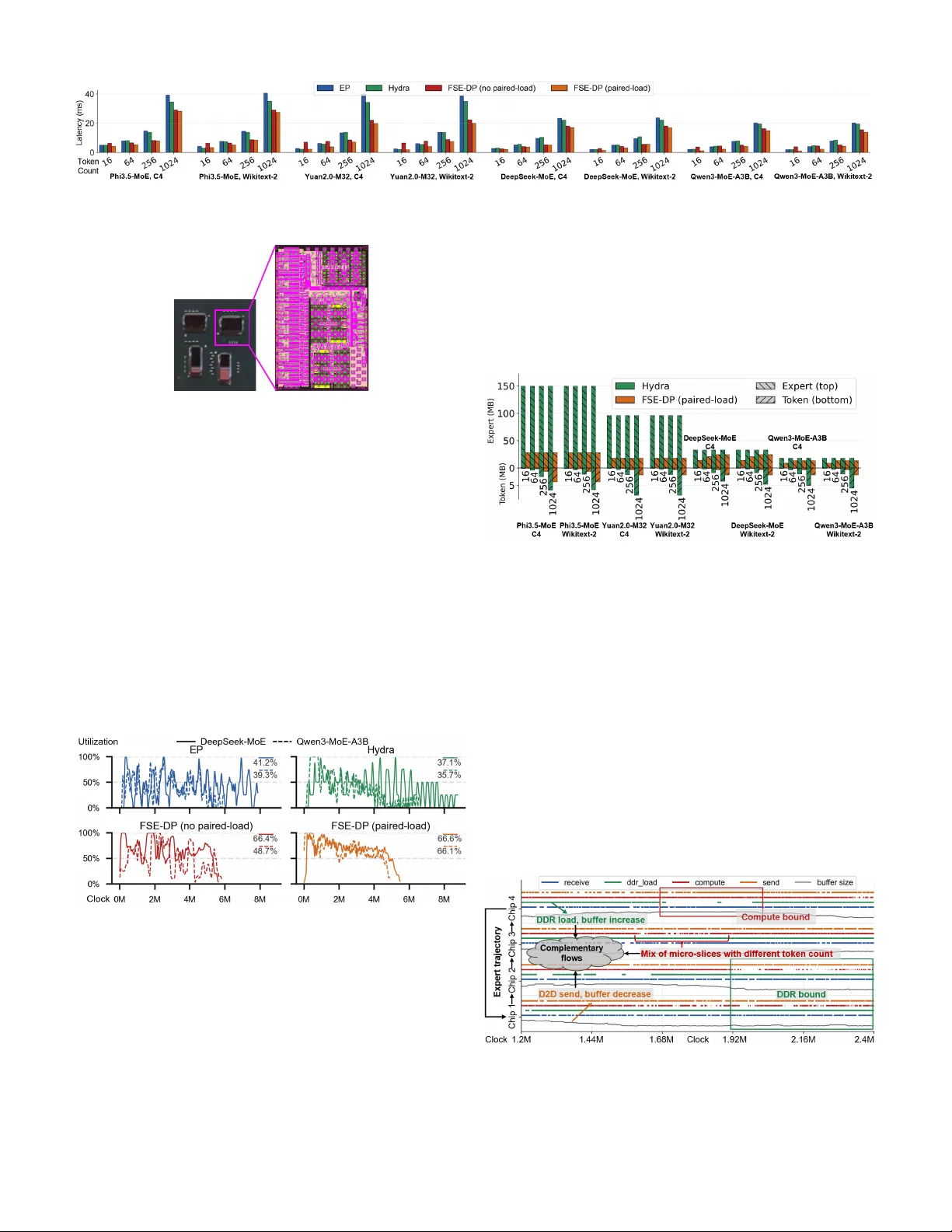
Expert Streaming: Accelerating Lo w-Batch MoE Inference via Multi-chiplet Architecture and Dynamic Expert T rajectory Scheduling Songchen Ma 1 , 2 † , Hongyi Li 2 † , W eihao Zhang 1 , 2 ∗ , Y onghao T an 1 , 2 , Pingcheng Dong 1 , 2 , Y u Liu 1 , Lan Liu 3 , Y uzhong Jiao 1 , Xuejiao Liu 1 , Luhong Liang 1 , Kwang-T ing Cheng 1 , 2 ∗ 1 AI Chip Center for Emerging Smart Systems, Hong K ong SAR, China 2 The Hong K ong University of Science and T echnology , Hong K ong SAR, China 3 Shanghai UniV ista Industrial Software Group Co., Ltd., Shanghai, China † Contributted euqally , ∗ Corresponding Authors (timcheng@ust.hk, weihaozhang@ust.hk) Abstract —Mixture-of-Experts (MoE) is a promising approach for edge AI with low-batch inference. Y et, on-device deploy- ments often face limited on-chip memory and sever e workload imbalance; the pre valent use of offloading further incurs off-chip memory access bottlenecks. Mor eover , MoE sparsity and dynamic gating shift distrib uted strategies toward much finer granularity and introduce runtime scheduling considerations. Recently , high die-to-die (D2D) bandwidth chiplet inter connects create new opportunities f or multi-chiplet systems to address workload im- balance and offloading bottlenecks with fine-grained scheduling. In this paper , we propose Fully Sharded Expert Data-parallelism (FSE-DP), a parallelization paradigm specifically architected for low-batch MoE inference on multi-chiplet accelerators. FSE- DP attains adaptiv e computation–communication ov erlap and balanced load by orchestrating fine-grained, complementary expert streams along dynamic trajectories across high-bandwidth D2D links. The attendant dataflow complexity is tamed by a minimal, hardware-amenable set of virtualization rules and a lightweight scheduling algorithm. Our approach achieves 1.22- 2.00 × speedup over state-of-the-art baselines and saves up to 78.8% on-chip memory . I . I N T R O D U C T I O N The increasing demand for real-time, priv acy-preserving AI services is dri ving the deployment of Lar ge Language Models (LLMs) onto edge devices. T o meet the escalating resource requirements of on-device scenarios such as AI PCs, robotics, and autonomous driving, chiplet-based multi-chiplet accelerators are emerging as a more scalable and cost-effecti ve solution than monolithic designs [80]. A multi-chiplet package designed for on-device AI typically inte grates multiple acceler - ator dies interconnected by high-bandwidth links and is usually coupled with large off-package memory , such as DRAM [33], [52], [61] (Figure 1(a)). Concurrently , the Mixture-of-Experts (MoE) architecture has gained prominence for its ability to reduce the number of parameters activ ated per inference while maintaining a large o verall model capacity [11], [22], [34], [39], [72], [75] (Figure 1(b)). The combination of multi- chiplet and MoE presents a powerful paradigm for high- performance on-device AI [28], where the sparsely activ ated large model can be distributed across chiplets to le verage spatial parallelism and high-speed inter-die communication. Despite this promising synergy , effecti vely deploying MoE models on multi-chiplet packages, particularly in on-device scenarios characterized by low batch sizes, introduces signif- icant challenges. First, limited on-chip memory : Although chiplet technologies significantly enhance the scalability of computational resources, on-chip SRAM-based cache remains a critical asset for on-de vice systems relativ e to LLM capacity [59]. Moreover , even de vices with large memory dies or GPUs equipped with high-bandwidth HBM still widely adopt off- loading strategies in edge deployments [3], [9], [10], [63], [81], o wing to the persistent demand for ever -larger models. It is therefore essential to minimize redundant storage and max- imize memory efficiency [25], [68]. Second, external mem- ory access bottleneck : Constrained on-chip capacity forces edge systems to off-load models, necessitating frequent, high- volume of f-chip traffic for both KV caches and expert weights. The reduced weight reuse in low-batch scenarios further exacerbates this issue. Third, dynamic workload imbalance : During each forward pass, the number of tokens assigned to each expert v aries—some e xperts process many tokens (hot experts), while others handle fe w or none (cold experts) [10], [25], [27], [85]. This long-tail distribution introduces two aspects of workload imbalance: (1) the compute-to-data- transfer ratio differs across e xperts, posing additional obstacles to overlapping off-chip memory access with computation; (2) the storage footprint and compute load di ver ge among chiplets, reducing ov erall utilization. Furthermore, low-batch conditions render traditional expert-balancing training [11], [71] or elastic containers [38], [60] used in the cloud inef fectiv e. These three challenges are tightly coupled with the characteristics of multi- chiplet architectures, and the latter two are further amplified by low-batch, on-device MoE workloads. Commonly-adopted parallel strategies—such as expert par- allelism (EP) [20], [34], [73] or hybrids that combine data parallelism (DP) [16], tensor parallelism (TP) [14], [19], [56], and pipeline parallelism (PP) [4]—fail to adequately address the aforementioned challenges in multi-chiplet inference set- tings. Most prior optimizations for edge de vices target GPUs and seldom e xploit the distinctive characteristics of chiplet- 1 Fig. 1. T ypical template of (a) multi-chiplet-based AI accelerator . (b) Mixture- of-Experts network. based packages. Recently , sev eral methods specialized for MoE inference on multi-chiplet have been proposed [17], [78]. These approaches generally aim to optimize inter-die communication, especially all-to-all communications in MoE, but they place less emphasis on addressing the long-tail issue and the external memory access bottleneck. Propelled by rapid adv ancements in adv anced packaging and high-speed communication technologies, the emer gence of cost-effecti ve and power -efficient die-to-die (D2D) intercon- nects with massiv e bandwidth and low latency—no w being standardized by protocols like UCIe [53]—is fundamentally recasting inter-die data transfer from a performance bottleneck into a rich architectural resource. Capitalizing on this sig- nificant opportunity , a novel parallelization strategy is ex- pected to not only fully exploit the intra-package communi- cation resour ce to enhance on-chip memory efficiency and curtail off-chip traffic, but also replace the expensive col- lective communication, inherent to traditional EP/TP , with highly efficient point-to-point transfers. Complementing the interconnection benefit, each chiplet typically possesses an independent control path, enabling chiplet arrays to exhibit a Multi-Instruction-Multi-Data (MIMD) character that supports asymmetric execution patterns. Consequently , load balance can be systematically engineered through a non-uniform yet mutually complementary mapping space [51], [80]. Collec- tiv ely , these two factors unlock opportunities for fine-grained, synchronization-free dataflow among chiplets [79]. Grounded in these observations, we propose Fully Sharded Expert Data- parallelism (FSE-DP), a specialized parallelization strategy tailored for MoE inference on multi-chiplet packages that deliv ers the following adv antages: Sav e on-chip memory and reduce off-chip memory traffic. The root cause of duplicated on-chip memory is the rigid ”one-chip-one-slice” mapping assumed by EP or TP . FSE-DP breaks this assumption by treating the whole chiplet array as a single, pooled buf fer: only one physical copy of any token/expert slice is k ept in the entire package. Leveraging high D2D bandwidth, FSE-DP streams the expert slice along a scheduled trajectory . The sa ved on-chip memory provides more data-reuse opportunities to reduce external memory access. Dynamic computation-communication ov erlap and load balancing. The long-tail distribution and dynamic features of MoE render fixed scheduling infeasible. FSE-DP introduces a dynamic fine-grained dataflow to realize each expert’ s trajec- tory , which turns this heterogeneity into an opportunity . By fusing and complementing the dataflow of expert trajectories with dif ferent load characteristics at fine granularity , FSE-DP achiev es dynamic computation-communication ov erlap under non-unified memory access (D2D and die-to-DDR), minimizes on-chip memory , and enables load balancing. Streamline fine-grained complexities with hardwar e- efficient rules and algorithms. The fine-grained dataflo w fusion ostensibly introduces intricate memory-access and com- munication patterns, significantly elev ating ex ecution com- plexity . Nevertheless, FSE-DP’ s dataflow is steered by a handful of lightweight, self-acting rules. Each chiplet receiv es the slice, computes its local token batch, and immediately forwards the slice to the next chiplet. These rules transparently abstract away memory and inter-die communication details from the programmer while letting the hardware spontaneously materialize the expert trajectories. Building upon this virtual- ization, a hardware-ef ficient runtime-scheduling algorithm and a dedicated hardware scheduler can be devised. Overall, this paper makes the following contributions: • Lev eraging high D2D bandwidth, we introduce FSE-DP , a distrib uted-parallel strategy tailored for multi-chiplet architectures that eliminates on-chip redundancy and re- duces off-chip DRAM traffic. • Architecting a fine-grained dataflow for e xpert trajecto- ries and fusing heterogeneous flows to achie ve adapti ve computation-communication ov erlap and load balancing. Along with this, we present a paired-load policy and token-b uffering policy to mitigate bandwidth bottlenecks. • Establishing a minimal set of virtualization rules for ex ecution abstraction that automatically orchestrate dy- namic expert trajectories under di verse workload scenar- ios, drastically simplifying both software programming and hardware-runtime complexity . • Presenting a hardware-ef ficient scheduling algorithm that unites temporal QoS-pressure-based queuing with spatial expert-trajectory planning. • Dev eloping a system to accelerate MoE-based large model inference. Our system includes a taped-out 2 × 2 5nm MCM test chip integrating a UCIe-compliant high- speed D2D interconnect, along with a lightweight, spe- cialized scheduler implemented as a synthesized R TL module that realizes our proposed algorithm. • Comprehensiv e e valuations on our system demonstrate that our approach not only achiev es significant perfor- mance gains o ver state-of-the-art baselines but e xhibits scalability and robustness. I I . B AC K G RO U N D A N D M OT I V AT I O N A. Related W orks MoE mitigates the widening gap between exploding model capacity and constrained hardware by activ ating only a sparse subset of expert sub-networks for each token. A gating func- tion selects the T op-K experts and aggregates their outputs, an 2 idea that can be applied to any parameter block, including the attention layer (Mix-of-transformers, MoT) [24], [70]. Originally popularized in the cloud, relatively small-scale MoE is now rapidly de veloped for edge scenarios [1], [35], [36], [43], [54], [65], [74], [75], [86]. Current MoE optimizations primarily focus on GPU sys- tems. Cloud-scale MoE deployments on GPU clusters predom- inantly optimize two points: (1) the all-to-all token–e xpert per- mutation traffic inherent in EP , and (2) load imbalance caused by ske wed expert popularity . Hybrid parallelism (EP+TP+DP) [19], [20], [56], pipelined or fused collectiv e communication [45], [55], [69], and specialized communication libraries [34], [48] are the main research topics for reducing inter-node traf- fic. For load balancing, auxiliary-loss-based training [11], [71] or elastic expert computation [7], [77] are common strategies to keep workloads uniform under large batches. MoET uner [13] optimizes expert placement across GPUs by solving an integer linear programming that jointly considers per-e xpert to- ken load and inter-layer routing dependencies, reducing inter- GPU token routing skew and tail latency . Some techniques use Fully Sharded Data Parallelism (FSDP) [82] to optimize MoE training, further sharding individual experts across GPUs and replacing all-to-all with cheaper all-gather/reduce-scatter operations [44]. Rotation-style distributed GEMM dataflows [12], [15] also explore how structured cyclic shifting can improve locality and ov erlap when data mov ement is unav oidable. For example, W aferLLM’ s MeshGEMM targets wafer -scale mesh NoCs and accelerates the prefill phase by combining cyclic shifting with an interleaving mapping, so that each core exchanges tiles with a fixed set of nearby neighbors and bounds the per-step communication cost to a constant hop distance (reducing both long-range latency and routing pressure). More broadly , these designs suggest that con verting global exchange into neighbor transfers can help overlap data mov ement and computation, although the y primarily target static , dense , and pr edictable GEMM. These efforts provide insights that we extend to chiplet systems via pure point-to-point weight transfers. For on-device inference scenarios with very limited GPU memory (e.g. NVIDIA R TX 3060 laptop only has 6GB mem- ory), systems usually rely on off-loading strategies, paging experts to CPU memory or SSD. This creates a cross-lev el data exchange and turns external bandwidth into the dominant bottleneck. Consequently , on-device-oriented studies focus on (1) expert prefetching with learned or heuristic predictors [8], [9], [30], [58], [76], (2) on-chip caching of hot experts [18], [83], and (3) run-time schedulers that ov erlap expert I/O with computation [26], [31], [68]. Emerging multi-chiplet accelerators open an under-e xplored design space. Current studies mainly focus on expert map- ping/placement to mitigate all-to-all communication [17], [78] or propose Content-Addressable Memory (CAM) to bypass token permutation [17]; some also explore run-time migration of e xperts to ward near -memory processors [19]. Y et, in on- device multi-chiplet settings, the off-loading pressure inherent to GPU-based systems and the statistical load imbalance persist simultaneously . B. Motivation Figure 2(a) characterizes contemporary MoE models. The results show that the dimension of a single expert ( D E xpert ) is generally smaller compared to the FFN ( D F F N ) and hidden size ( D M odel ). This makes the computational granularity of the experts finer-grained, with lower computational demands but still places very high demands on memory bandwidth [85]. E x p e rt s (sorte d b y to ke n co u n t) Cou n t o f T o ke n s Ex pe r ts (sor te d by to ken cou nt ) Cou n t o f T o ke n s (c) Q w en 3 - 30B - A 3B - La y e r 24 (W in o G rand e) (a) MoE Model Par amet ers Model D M o d e l D FFN D E x p e r t DeepS eek MoE 2048 10944 1408 DeepS eek - V3 7168 18432 2048 Q w en3 - 30B - A3B 2048 6144 768 Q w en1.5 - MoE 2048 5632 1408 O LMoE 2048 8192 1024 DeepS eek - V2 7168 18432 2048 Multip le experts w ith limit ed experts siz e com pared to hid den siz e. (b) DeepSeekM oE - 16B - Lay er 13 ( W ikitext - 2 ) Fig. 2. (a) Shapes for different models (b,c) Long-tail effect of MoE models under dif ferent batch sizes. The figure shows the number of tokens processed in a specific layer for DeepSeek-MoE-16B [48] on the Wikite xt-2 dataset [41] and Qwen3-30B-A3B [75] on WinoGrande [49]. Experts on the x-axis are sorted by the number of tokens they process; the y-axis giv es the token count per expert. The long-tail effect is more pronounced at smaller token numbers. R denotes different requests. Furthermore, we profile expert activ ation in state-of-the-art MoE networks on language datasets. Figure 2 (b) and (c) highlight the pronounced long-tail effect : although these MoE models incorporate expert-balancing losses during training, inference still exhibits large disparities in per -expert token counts for batched tokens ranging from 16 to 256. A non- negligible fraction of experts process only a handful of tokens, yet their full weights must be fetched, creating severe band- width pressure and necessitating strategies that maximize data reuse once loaded onto the chip. Howe ver , e xisting DP and sequence parallelism (SP) [29] replicate entire experts across chiplets, incurring weight redundancy . TP shards experts but duplicates tokens, while EP also mandates token replication, compounding the memory-traffic challenge. Many edge deployments also operate in a low-batch regime that aggregates the long-tail ef fect: on-device systems in- creasingly run multiple concurrent, mixed-latency tasks (e.g., agentic workloads with time-varying concurrenc y , robotics pipelines that couple perception/reasoning/action, and multi- sensor streaming). Compared with cloud serving, ef fecti ve concurrency is typically smaller, which weakens cross-request weight reuse and makes off-chip expert fetch under long-tailed activ ations a primary bottleneck. The evolution towards multi-chiplet AI accelerators, driv en by advanced packaging, has unlocked new architectural affordances for lar ge-scale models: ultra-high-bandwidth, low-latenc y D2D links and per-chiplet independent con- trol that enables MIMD-style asymmetric dataflows. Multi- 3 chiplet design disaggregates the system into smaller, function- specific dies for better manufacturing yield and design reuse [50], allowing for fine-grained, synchronization-free pipelines rather than device/rack-le vel pipelines in GPU- based systems. This progression began with standard pack- aging, Multi-Chip-Modules (MCMs), exemplified by Nvidia’ s Simba accelerator, which used a proprietary D2D intercon- nect to achie ve 100 GB/s/chiplet bandwidth at 20 ns/hop and 0.82–1.75 pJ/bit [52]. Subsequent advancements in 2.5D heterogeneous integration [5], [62] hav e pushed performance further , with recent systems demonstrating an aggregate band- width of 20 Tb/s across 20 chiplets [59]. Howe ver , realizing the full potential of this packaging spectrum—from cost- effecti ve 2D MCMs [66], [84] to high-performance 2.5D systems—was historically hindered by a fragmented landscape of proprietary interconnects (e.g., AMD’ s Infinity Fabric) and early open specifications (e.g., OCP-ODSA ’ s BOW). The emergence of the UCIe standard [53] mark ed a pi votal shift, creating a unified ecosystem by providing optimized options for both adv anced (UCIe-A) and standard (UCIe- S) packages [42]. This dual-pronged strategy’ s strength is confirmed by recent industrial implementations. For advanced packages, D2D links in 3nm have demonstrated a remarkable bandwidth density of up to 10.5 Tb/s/mm [32], while other work has shown an energy efficienc y of just 0.29 pJ/b [40]. Concurrently , for standard packages, 3nm UCIe-S transceiv ers provide a competiti ve 0.448 Tbps/mm at 0.52 pJ/bit [67]. This conv ergence of versatile packaging technologies with a prov en, unified open standard [23], [59], [62] is finally de- liv ering the low-latenc y , energy-efficient, and high-bandwidth D2D interconnects essential for next-generation computing. This robust hardware foundation creates an unprecedented opportunity to leverage a rich “communication bandwidth resource, ” yet exploiting its div erse affordances demands nov el parallelization strategies. I I I . N A I V E F U L LY S H A R D E D E X P E RT P A R A L L E L When the D2D interconnect ceases to be a performance bottleneck and instead becomes an exploitable resource, the optimization paradigm shifts from intra-die communication, which is the main focus of existing parallel strategies, to of f- chip access and the elimination of on-chip redundanc y , thereby maximizing data reuse. Building on this insight, we introduce Fully Sharded Expert-Data Parallelism (FSE-DP). Inspired by FSDP in distributed neural-network training, where both inputs and model parameters are sharded across de vices, FSE-DP also partitions token sequences and expert weights across chiplets. W e refer to each forward pass as an iteration. During an iter - ation, FSE-DP processes the MoE network layer -wise, keeping token activ ations on-chip while fetching expert weights from DDR on demand. T o illustrate the core idea, consider a 4- chiplet array that handles one expert at a time (Figure 3). The current iteration aggregates tokens from multiple requests (combining prefilling and decoding, a widely adopted strategy called chunked prefill [2]). These tok ens are ev enly sharded across the four chiplets, so ev ery chiplet holds one fourth of the tokens. In Figure 3, “R1-T9” denotes the activ ation vector of the 9th token from Request-1. For each expert, the set of tokens that activ ate it varies dynamically . Consequently , prior to computing each expert, we redistribute the tokens that activ ate the current expert to ensure that the number of tokens processed by each chiplet is approximately equal for load balancing. In this example, we designate the token sequences computed by each chiplet as Seq-A to Seq-D, with the lengths of Seq-A through Seq-D kept roughly equal. W e also partition expert 1 into four slices (E1-S1 through E1-S4) across chiplets. In the first computation phase, illus- trated in Figure 3, chiplet 1 processes Seq-A with E1-S1, chiplet 2 processes Seq-B with E1-S2, and so on. In the second phase, as shown in Figure 3(a), we perform a circular transfer of e xpert slices across chiplets: chiplet 1 sends E1-S1 to chiplet 2; chiplet 2 sends E1-S2 to chiplet 3; chiplet 3 sends E1-S3 to chiplet 4; and chiplet 4 sends E1-S4 to chiplet 1. Each chiplet then computes its token sequence using the ne wly received expert slice. In subsequent phases, this pattern of expert-slice circulation and computation continues under the same rules until all computations for this expert are completed. In current MoE-parallelism approaches, transmitting ex- pert weights is seldom adopted because the weight volume typically exceeds that of token activ ations. Indeed, when a multi-chiplet system computes a single isolated expert, fix- ing the weights and exchanging token sequences achie ves comparable parallelism, as illustrated in Figure 3(b). When the token sequence is small, inter-chiplet token transmission is more attractiv e. Howe ver , as discussed earlier , properly engineered advanced interconnects broaden the design space for weight-transmission strategies. When D2D communication is acceptable, transmitting expert slices offers additional ben- efits, enabling improv ed overlap between DDR loading and computation while reducing on-chip memory and bypassing token redistribution. I V . F S E - D P W I T H M I C R O - S L I C E F L O W W e improv e FSE-DP by centering on computation- communication overlap. Computation-communication ov erlap is essential in neural-network acceleration to mitigate perfor- mance loss from communication overhead. In multi-chiplet systems, beyond the attention phase, overlap should be ex- ploited in three key scenarios: (1) inter-chiplet data exchange, where chiplets compute on the current data while simultane- ously transmitting the next expert slice or token sequence; (2) on-chip computation of the current expert while pre-loading weights for the next expert from DDR. Considering these scenarios, we identify two principal limitations of the basic FSE-DP approach: (1) regardless of whether weights or tokens are exchanged between chiplets during expert computation, each chiplet requires extra storage to hold data for the up- coming computation; for example, when expert slices are transmitted in FSE-DP , e very chiplet needs additional space for the next expert slice, nearly doubling the on-chip memory requirement for expert weights; and (2) although FSE-DP alone can balance computation and storage, coordinating it 4 Time 1. T oken redispatch 2. Computation and Data Circling Expert computing - phase 1 Phase 2 Phase 3 Phase 4 T oken Buffer T oken Buffer ... Redispatch R1-T9 R2-T8 R3-T8 R4-T5 R5-T3 Chiplet 1 R1-T9 R2-T8 R3-T8 R4-T5 R7-T5 Seq-A R7-T1 R7-T2 R7-T3 R7-T4 R5-T3 Seq-B R8-T6 R8-T7 R8-T8 R8-T9 R8-T10 Chiplet 4 R8-T1 R8-T2 R8-T8 R8-T9 R8-T10 Seq-D R8-T6 R8-T7 R8-T3 R8-T4 R8-T5 Seq-C Chiplet 3 R8-T1 R8-T2 R8-T3 R8-T4 R8-T5 R7-T1 R7-T2 R7-T3 R7-T4 R7-T5 Chiplet 2 An expert is fully sharded across chiplets. Fix token sequences, exchange expert slice Fix expert, exchange token sequence Seq-B E1-S 3 Seq-A E1-S 2 Seq-B E1-S 4 Seq-A E1-S 3 Seq-A E1-S 4 Seq-B E1-S 1 Seq-D E1-S 1 Seq-C E1-S 4 Seq-D E1-S 2 Seq-C E1-S 1 Seq-D E1-S 3 Seq-C E1-S 2 Seq- D E1-S3 Seq- A E1-S4 Seq- A E1-S3 Seq- B E1-S4 Seq- B E1-S3 Seq- C E1-S4 Seq- B E1-S1 Seq- C E1-S2 Seq- D E1-S2 Seq- C E1-S1 Seq- A E1-S2 Seq- D E1-S1 Expert Buffer R1-T9 R2-T8 R3-T8 R4-T5 R7-T5 Seq-A Chiplet 1 Expert Buffer R7-T1 R7-T2 R7-T3 R7-T4 R5-T3 Seq-B Chiplet 2 Expert 1- Slice 1 (E1-S1) Other Experts Expert 1- Slice 2 (E1-S2) Other Experts Expert Buffer R8-T6 R8-T7 R8-T3 R8-T4 R8-T5 Seq-D Chiplet 3 Expert Buffer R8-T1 R8-T2 R8-T8 R8-T9 R8-T10 Seq-C Chiplet 4 Expert 1- Slice 4 (E1-S4) Other Experts Expert 1- Slice 3 (E1-S3) Other Experts Fig. 3. Fully sharded expert–data parallelism (example: four chiplets compute expert 1). The figure illustrates how a single expert is computed within one MCM: expert 1 is evenly sharded into slices across chiplets (E1-S1–E1-S4). black tokens denote the tokens that activate expert 1, while non-highlighted (gray/black) tokens are other buffered tokens on that chiplet that do not activ ate expert 1. Before computing expert 1, tokens are redispatched across chiplets to balance the number of black tokens per chiplet for load balancing. R denotes a request, and Seq denotes the activated token sequence stored on a chiplet. During expert computation, chiplets can exchange data in two equiv alent ways to cover all black tokens: (a) keep token sequences fixed and circulate expert-1 slices so each slice visits the chiplets holding black tokens; or (b) keep expert 1 slices fixed and circulate black-token sequences so they visit all chiplets containing slices of expert 1. Time E1-S1 E1-S4 E1-S3 E1-S2 Time E1-S1 E1-S4 E1-S3 E1-S2 Send M1 Send M2 Send M4 Send M3 Recieve M1 Recieve M2 Recieve M4 Recieve M3 Send E1-S4 Send E1-S3 Send E1-S1 Recieve E1-S3 Recieve E1-S2 Chiplet 1 Compute Seq-A , E1-S4 Compute Seq-A , E1-S1 Compute Seq-A , E1-S3 Compute Seq-A , E1-S2 Discard A Micro-slice E1-S2-M1 E1-S3-M1 E1-S4-M1 Compute Seq-A , M1 Discard Compute Seq-A , M2 Discard Compute Seq-A , M4 Discard Compute Seq-A , M3 Discard E1-S1-M1 ( a ) ( b ) Recieve E1-S4 Expert Buffer 1 2 3 4 1 2 2 3 4 1 2 3 3 4 1 2 3 4 4 1 2 3 4 1 1 2 3 4 1 2 3 3 4 1 2 3 4 4 1 2 3 4 1 1 2 3 4 1 2 2 3 4 1 2 3 4 4 1 2 3 4 1 2 3 4 2 3 4 3 4 A Buffer Slot 2 3 4 2 2 3 4 2 2 3 4 2 3 4 2 3 4 3 3 4 3 3 4 3 4 3 4 4 4 4 4 4 4 1 2 3 4 1 1 2 3 4 1 1 2 3 4 1 2 3 4 1 E1-S1-M1 Fig. 4. Micr o-slice flow for overlapping D2D communication and computation (example: chiplet 1 while computing expert 1). Each expert slice (E1-S1–E1-S4) is further partitioned into micro-slices (M1–M4). (a) Baseline micro-slice overlap. In each step, chiplet 1 computes its local sequence using the current micro-slice, while concurrently receiving the next micro-slice from a neighbor chiplet and sending the just-computed micro-slice to the next chiplet; arrows indicate the D2D transfers that overlap with the compute stage. The weight buf fer show the micro-slice storage on chiplet 1 over time, where each row is one micro-slice-sized buf fer slot and each column is a time step. A colored cell indicates that the slot stores a micro-slice from a specific expert slice (see the color legend), and the numeral in the cell is the micro-slice index within that slice. Blank cells are free slots, and bold numerals mark the micro-slice being computed in that step. (b) Eager micro-slice usage. Chiplet 1 immediately forwards the micro-slice under computation and, in the next step, computes the most recently receiv ed micro-slice, so each micro-slice quickly trav erses all chiplets and can be discarded earlier, reducing average weight-buf fer occupancy . with attention computation is challenging because v arying KV - cache sizes across requests preclude uniform partitioning of expert and sequence slices at the start of expert computation. T o reduce the storage ov erhead of communication buf fers, a straightforward approach is to reduce the granularity of computation-communication operations. Using expert weight transmission in FSE-DP as the example, we further partition each expert slice on a chiplet into multiple micro-slices, treating each micro-slice as the fundamental unit for FSE- DP computation and transmission. As illustrated in Figure 4(a), while a chiplet computes one micro-slice of its current expert slice, it concurrently recei ves a micro-slice from the next expert slice scheduled for computation. Upon completing the current micro-slice, the chiplet releases the associated storage space. After all micro-slices of the current expert hav e been processed, the chiplet will hav e accumulated the full set of weight slices for the next expert. This approach can be implemented with a micro-slice–based ring buf fer—a mature hardware technique—thereby reducing the additional storage overhead of computation-communication ov erlap to the size of a single micro-slice. The number of micro-slices reflects a trade-off between ov erlap opportunity and ov er- head. Finer micro-slices improv e pipelining and reduce the required communication-buf fer , but also increase relativ e con- trol/scheduling overhead and per -transfer header cost, leading to diminishing returns when a micro-slice becomes too small. A practical approach is to choose a micro-slice size such that its computation time is roughly comparable to its D2D transfer time, maximizing overlap while preventing control/dispatch ov erhead from becoming the bottleneck. 5 Departing from the straightforward approach, we introduce an uncon ventional micro-slice–centric optimization of the fine- grained flow shown in Figure 4(a). When a token completes computation in a giv en layer, it produces a new acti vation vector of the same size. By contrast, once weight computation finishes, those weights are not reused within the current iter- ation; hence, their on-chip memory can be released immedi- ately . Guided by this observation, the principle for fine-grained optimization is to complete all computations for each micro- slice as quickly as possible, release its space, and then proceed with computations for other micro-slices . Applying this rule yields the pipelined pattern shown in Figure 4(b). Although the pattern may appear complex, its rules are simple: each chiplet immediately transmits the micro-slice it is currently computing and, in the next time step, processes the most r ecently receiv ed micr o-slice . These rules ensure that once a micro-slice begins computation, it is promptly swept into the dataflow circulating among chiplets, completes all token computations, and occupies on-chip memory for the shortest possible time. As shown in Figure 4(b), this approach can sav e nearly half of the on-chip memory (more than half if an expert is not pre-loaded). A. Expert Load Optimization T o capitalize on the buf fer headroom and timing regularity created by the micro-slice flow and to prepare the subsequent fusion of DDR load with D2D flo w , we first present our e xpert- load order optimization. Hot experts incur intensive computa- tion workloads, whereas cold experts exhibit prominent com- munication bottlenecks in the long tail, which suggests pairing hot and cold e xperts. Accordingly , we sort experts by their token-acti vation counts and pair experts from opposite ends of the list, interleaving on-chip fetch and compute, as sho wn in Figure 5. This paired-load policy aligns with the micro-slice cadence, increases overlap between communication-bound and compute-bound experts (Section IV -B). Ex per ts (Sor ted by token c ount) Nu m be r of T ok en s 4 8 12 16 0 ··· ··· T oken Buf fering Zo ne Pair ed Expert Lo ad Hot ex per ts Col d experts Fig. 5. Demonstration of paired-load policy and token buffering policy . For long-tail experts activ ated by only a fe w tokens, loading them onto the chip leads to highly inefficient bandwidth utilization due to low data reuse. Accordingly , rather than processing these tokens in the current iteration, we use token buffering as a per-r equest deferral mechanism at the specific MoE layer: when a request’ s tokens are routed to an extremely cold expert that is not scheduled for immediate execution, the scheduler can pause the entire r equest at that MoE layer , holding its intermediate activ ations. In the following iterations, these tokens can be combined with newly arriving tokens of other requests to ev aluate e xpert-activ ation patterns. While this increases that request’ s latency , LLMs typically require multiple forward passes during decoding. For example, when generating 4k tokens of text, permitting a 10% increase in total completion time yields more than 400 opportunities for token buf fering. Moreover , in LLM scenarios, per-request quality-of- service (QoS) requirements are often flexible, making it rea- sonable to trade some per-request performance for improved ov erall system efficiency . In Section V, we present detailed methods for applying token buffering. The paired-load and token-buf fering policies are compatible with expert-prediction prefetch techniques, such as Pre-Gated MoE [21]. During the computation between the previous layer’ s FFN and the current layer’ s attention, expert load can be reordered based on predicted expert-acti vation patterns. W ith accurate prediction, the scheduler can commit to an expert order early and start prefetching to better hide latency . If predictions are inaccurate, both load reordering and token buf fering can be updated again after the MoE gate of the current layer . Moreover , because scheduling operates at ex- pert granularity , much of the remaining decision latency can ov erlap with the ex ecution of other experts. B. Flow Fusion While the micro-slice flow effecti vely optimizes D2D com- munication, the primary performance bottleneck often remains the communication between the chip and off-chip DDR mem- ory , which is substantially slo wer . Accordingly , we le verage the on-chip memory saved by the D2D flow to fuse it with the chip-to-DDR flow , thereby achieving further overlap of com- putation with DDR loading within the same on-chip memory budget. W e illustrate this fusion using chiplet 1 in Figure 6. In this example, we complementarily load and compute E1 and E4 on-chip (paired-load policy): chiplet 1 loads slice 1 of E1 and E4 from DDR and receives slices 2–4 from other chiplets. W e assume that loading a micro-slice from DDR takes four times as long as computing a micro-slice. In Figure 6, the first tw o rows of the weight b uf fer store micro-slices of E1 and E4 loaded from DDR, respecti vely , while the subsequent three ro ws are reserved for the inter - leav ed reception of micro-slices from other chiplets. Through fine-grained fusion of the DDR-load flow and the D2D flo w , we ov erlap transmission and computation for two experts. At each time step, a chiplet computes one micro-slice from E1 and one from E4, preserving load balance while keeping the maximum expert-b uffer usage the same as in Figure 4(b). This figure shows an ideal model to illustrate the principle. Note that dif ferent ratios of DDR load time to micro-slice compute time yield different expert-buf fer utilization patterns. Ratios lar ger than those shown in Figure 6 may require more buf fer storage (Section VI-D), although the allocation rules and ov erall fusion pattern remain consistent (Section IV -C). C. Execution Abstraction via V irtualization Rules Up to this point, we hav e detailed the benefits of fine- grained pipelining and its basic arrangement. Nevertheless, a 6 Chiplet 1 Expert Buffer Time E1-S1 E1-S4 E1-S3 E1-S2 E4-S1 E4-S4 E4-S3 E4-S2 Compute Send M3 Send M2 Send M4 Send M4 Send M1 Recieve M1 Recieve M2 Recieve M3 Recieve M4 Send M1 Sned M2 Send M3 Recieve M4 Recieve M3 Recieve M2 Recieve M1 Compute DDR load E1-S1-M1 DDR load E1-S1-M2 DDR load E4-S1-M1 DDR load E4-S1-M2 DDR load E1-S1-M3 DDR load E1-S1-M4 DDR load E4-S1-M3 DDR load E4-S1-M4 Compute Compute 2 2 2 1 1 3 2 2 2 1 3 2 2 2 2 3 3 2 2 2 3 3 3 2 2 4 3 3 3 2 4 3 3 3 3 4 4 3 3 3 4 4 4 3 3 4 4 3 3 4 4 3 4 4 4 4 1 1 1 2 1 1 1 2 1 1 1 1 2 2 1 1 1 1 1 1 4 4 1 4 Die-to- Die Fig. 6. Flow fusion of DDR load and D2D micro-slice flow (example: chiplet 1 while computing expert 1 paired expert 4). This figure extends Figure 4(b) by fusing off-chip DDR loading with the on-chip D2D micro- slice circulation, illustrated on chiplet 1 while co-executing two experts (E1 in red and E4 in purple under paired-load). DDR loads of the locally assigned micro-slices (e.g., E1-S1-M* and E4-S1-M*) are pipelined with computation and D2D receive/send of micro-slices from other chiplets. DDR load latency is assumed to be 4 × one micro-slice compute step. The expert-buf fer grid is read as in Figure 4: the first two rows cache DDR-loaded micro-slices for E1 and E4, respectively , while the remaining rows serve as a shared staging area for interleaved D2D-received micro-slices from both experts. Bold numerals indicate the micro-slices being computed at each time step. significant challenge arises: under dynamic and imbalanced workloads, when multiple experts are fused concurrently , and with heterogeneous DDR and D2D links, the resulting micro- slice storage and communication patterns can become exceed- ingly complex. Even the flow in Figure 4(b)—an idealized case with two uniformly distributed experts—already exhibits substantial complexity for manual pipeline scheduling. Di- rectly or chestrating this level of complexity at runtime is prohibiti ve f or both software programmability and hard- ware implementation. Theref ore, this section intr oduces a “virtualization” method. The “virtualization” abstracts away dynamic physical details, e.g., which micro-slice resides in which buf fer slot and which link it traverses at which cycle. Behind a small set of rules, the scheduler can reason at the lev el of expert trajectories rather than per-micro-slice book- keeping. By following these rules, complex flow orchestration can be realized while ensuring low hardware implementation costs. From our previous discussion, the core of FSE-DP is to enable expert parameters to flow through all chiplets responsi- ble for token computation along a trajectory . As long as each micro-slice visits ev ery station, the starting point, endpoint, timing, and intra-trajectory ordering of micro-slices are im- material (the result of a token–expert computation can be ac- cumulated on the same chiplet without tracking which micro- slice is being processed). Consequently , the specific storage locations of micro-slices or token activ ations on chiplets, and their transmission schedules among chiplets, are of secondary importance, provided their paths follow the trajectory . In our dynamic scheduling, trajectories are decided at expert granularity: different e xperts may choose different chiplets and flow directions at runtime, while once a trajectory is selected for an expert in a scheduling iteration, all micro-slices of that expert follow the same trajectory . W e do not implement per- micro-slice dynamic paths because tracking per-micro-slice trajectory state and next-hop decisions would substantially increase scheduler metadata and hardware complexity . Ev en S h ar d i n g (a) t=1 t=2 (c) t= 1 E1 - M1 C hiplet 2 E1 - M1 Chiplet 1 E1 - M5 C hiplet 3 E1 - M 1 3 Chiplet 4 E1 - M5 E1 - M9 E1 - M9 E1 - M 13 t=2 E1 - M1 Chiplet 2 E1 - M9 C hiplet 1 E1 - M5 Chiplet 3 E1 - M5 C hiplet 4 E1 - M 13 E1 - M1 E1 - M9 E1 - M 1 3 t=3 E1 - M9 C hiplet 2 E1 - M9 C hiplet 1 E1 - M 13 C hiplet 3 E1 - M5 C hiplet 4 E1 - M 1 3 E1 - M1 E1 - M1 E1 - M5 ( b ) C hiplet 2 E1 - M1 Chiplet 1 E1 - M9 E1 - M9 C hiplet 3 E1 - M 1 0 E1 - M 1 6 Chiplet 4 E1 - M 10 E1 - M 16 E1 - M1 Chiplet 2 E1 - M 10 C hiplet 1 E1 - M 16 E1 - M9 Chiplet 3 E1 - M1 E1 - M9 C hiplet 4 E1 - M 1 0 E1 - M 1 6 E1 - M1 Chiplet 2 E1 - M 1 0 C hiplet 1 E1 - M 1 6 E1 - M 16 Chiplet 3 E1 - M1 E1 - M9 C hiplet 4 E1 - M1 E1 - M9 E1 - M 10 C hiplet 2 E1 - M9 C hiplet 1 E1 - M1 C hiplet 5 C hiplet 4 E2 - M9 E2 - M9 E1 - M9 E1 - M 1 0 E2 - M1 C hiplet 3 E3 - M9 C hiplet 6 E2 - M1 E3 - M8 E1 - M 10 DDR E1 - M1 E2 - M9 E1 - M1 C hiplet 2 E1 - M1 Chiplet 1 E1 - M9 C hiplet 5 E1 - M 1 0 Chiplet 4 E2 - M1 E2 - M9 E1 - M9 E2 - M1 C hiplet 3 E3 - M8 C hiplet 6 E2 - M9 E3 - M8 S tead y S tr eami n g (1 m ic ro - s lic e per c hiplet per s t ep) U n ev en Pl acemen t S tead y S tr eami n g (1 m ic ro - s lic e per c hipl et per s t ep) F u sed U n ev en F l o w s 1 2 4 5 E1 : C hiplet E3 : C hiplet 3 6 E2 : C hiplet 2 3 5 6 4 C om put e R ec eiv e Fig. 7. Virtualization demonstration under micro-slice streaming (ex- ample: 4 chiplets, ring expert trajectory). Each panel shows the on-chip storage state of the four chiplets at three consecutive time steps ( t =1 – 3 ): each block is a stored micro-slice (labeled by expert and index, e.g., E1-M1), and arrows indicate ne xt-hop forwarding along the ring trajectory . (a) Baseline case where expert 1 is evenly sharded across chiplets; achieving efficient overlap with explicit buffer assignment requires careful placement (as in Figure 6). (b) Expert 1 is une venly distributed across chiplets, yet the computation proceeds correctly once micro-slices start streaming along the trajectory . For simplicity , (a) and (b) assume a ring topology in which micro-slices move from Chiplet 1 to 2, 2 to 3, and so on, to introduce the background of virtualization.(c) There experts ex ecute concurrently with highly unev en on-chip arrangement. Despite the seemingly irregular trajectories, virtualization rules abstract away these runtime details and still realize a smooth flow . The key message is that the hardware scheduler need not reason about per-chiplet implementation: as long as micro-slices follow the prescribed trajectory , correct and efficient execution emerges without fine-grained bookkeeping. Figure 7 illustrates ho w runtime storage details are irrelev ant to the smooth streaming of micro-slices along an expert tra- jectory . Figure 7(a) shows the baseline case where expert 1 is ev enly sharded across 4 chiplets. The per-chiplet weight buffer is shown over three time steps. Figure 7(b) then sho ws that ev en when E1’ s micro-slices are une venly distributed across chiplets, once the micro-slices begin to flow among chiplets, we can still realize a fine-grained flow equiv alent to that in Figure 4(b) while maintaining balanced expert computation across all chiplets. For clarity , we simplify the notation by moving from a two-level partitioning (expert slice to micro-slice) to a single level, in which an expert is directly partitioned into a set of micro-slices. For instance, if expert E1 is divided into 16 micro-slices, we denote them as E1- M1 through E1-M16. This change does not alter the concepts discussed previously . 7 This equiv alence further extends to the case where multiple experts ex ecute concurrently , as shown in Figure 7(c), where different colors denote micro-slices from distinct experts. Like- wise, the expert flow fusion achie ves a similar effect to Figure 4(b); the specific distribution and the per-chiplet compute duration of a micro-slice (how many tokens are processed) do not affect the aggre gate four-e xpert flow . This “computation and storage-distribution independence” also extends to DDR memory: regardless of storage location, weights can be swept into the dataflow once loaded onto the chip during expert computation. The DDR-load flow can be naturally fused with the D2D flow without detailed pipeline coordination. Based on the preceding analysis, the expert flow can be re- alized automatically; the key question is whether it is efficient. Y es—under the following virtualization rules: Rule 1: A micro-slice recei ved in the previous time step is computed immediately in the current time step while simultaneously being transmitted to the next chiplet along the trajectory . Rule 2: If no micro-slice was receiv ed in the previous time step, the chiplet selects any micro-slice from its local storage for immediate computation and transmission. Rule 3: If there is no next chiplet on the path, the storage occupied by the micro-slice is released immediately after computation. Rule 4: Chiplets sequentially load the next micro-slice from DDR whenev er there is available space. Rule 5: DDR controller ”sends” micro-slices to the chiplet with the greatest a vailable storage among those pro- cessing the expert (Optional). W ith these rules, similar “communication-pattern indepen- dence” can be deduced: under varying ratios of DDR-load to D2D bandwidth, runtime fluctuations, or backpressure, the fused flows self-adapt without detailed pipeline coordination. Such adapti vity is essential when handling dynamically vary- ing and imbalanced on-chip memory , link utilization, and per-e xpert token counts, as it enables the expert flow to automatically exploit computation (Rules 1 and 2) and com- munication (Rules 1 and 4) while minimizing on-chip memory (Rules 2 and 3) resources. Furthermore, because different experts exhibit distinct computation-communication character- istics, these rules allow the fused expert flo w to adapti vely complement heterogeneous resource usage. In essence, this mechanism functions as a form of hardware-lev el virtualiza- tion, where the shared physical resources—buf fers, D2D links, and compute units—are dynamically multiple xed across the logical dataflows of multiple experts. By decoupling the log- ical trajectory of micro-slices from static physical allocation, the system allows concurrent expert flows to fluidly contend for and utilize the chiplet array’ s aggregate capacity , resolving local contention and maximizing utilization without the need for cycle-accurate global orchestration. In our ev aluation, we also find that this complementation effecti vely addresses inter- expert load imbalance and intra-expert differences in the number of tokens that must be processed along the expert trajectory . In other words, FSE-DP no longer needs token redistrib ution , and all intra-package communication can be simplified to expert point-to-point e xchange. Rule 5 is an optional optimization and is not implemented in our end-to- end system; our ablation study (Section VI-C) sho ws that its incremental benefit is limited when other mechanisms (paired-load and flow fusion) are enabled in MoE scenarios, while efficient implementation may require complex metadata tracking in the scheduler or DDR controller . V . C H I P L E T S Y S T E M W I T H M O E S C H E D U L E R Thanks to virtualization, deployment and scheduling reduce to managing expert trajectories. W e propose a scheduling algorithm that orchestrates these trajectories to sustain high hardware utilization under dynamic MoE workloads and asym- metric spatio-temporal chiplet execution patterns. Guided by the virtualization rules, we design and synthesize a lightweight hardware scheduler that realizes this algorithm on a multi- chiplet system equipped with high-speed D2D transceiv ers. A. Scheduling Algorithm Algorithm 1 Spatiotemporal T rajectory Scheduling Algorithm Require: Expert set E , chiplet set C , idle chiplet set C idle ← C . Ensure: A dynamic loading sequence of experts with the trajectory T e for each expert e that pursues C idle = ∅ . 1: Sort E by paired-load policy to an ordered list E sorted . 2: while not all experts is scheduled ( E sorted = ∅ ) do 3: if C idle = ∅ then 4: for each expert pair ( e 1 , e 2 ) in E sorted do 5: Get T e from chiplets with tokens for e in ( e 1 , e 2 ) . 6: if there are idle chiplets in the trajectory ( T e ∩ C idle = ∅ ) then 7: Stream e ’ s micro-slice to c ∗ ∈ T e ∩ C idle . 8: Update idle chiplets: C idle ← C idle \ T e . 9: Remov e e from E sorted . 10: break 11: end if 12: Rule 4: Pre-load e to any idle buf fer . 13: end for 14: end if 15: When expert e ′ completes: C idle ← C idle ∪ new idle chiplets in R e ′ . 16: end while Algorithm 1 presents a dynamic expert scheduler that assigns experts to chiplets based on token locality and re- source av ailability . Its objectiv e is complete resource utiliza- tion—pursuing the condition C idle = ∅ —so that all chiplets remain activ ely engaged in computation. Scheduling begins by ordering experts under a paired-load policy , which prioritizes experts according to complementary computation and com- munication requirements, yielding an ordered priority queue E sorted . The main loop repeatedly fetches schedulable experts in priority order and performs resource-aw are allocation that respects chiplet av ailability and trajectory constraints. 8 For each expert e , the algorithm deri ves a trajectory T e representing the path across chiplets that hold cached tokens relev ant to e . The expert is scheduled only if its trajectory intersects the idle-chiplet set ( T e ∩ C idle = ∅ ). When such an intersection exists, the algorithm selects an idle chiplet c ∗ to load a micro-slice of e ; execution then proceeds automatically under Rules 1–3. Upon successful allocation, the idle set is updated by removing chiplets assigned to the expert’ s resource requirements ( R e ), and the scheduled expert is removed from E sorted . If the paired e xpert cannot cov er any idle chiplet at the moment, it is pre-loaded on any chiplet with an idle buf fer according to Rule 4. Rule 5 is not considered for implementation. When any expert e ′ completes, chiplets not engaged by other running experts are returned to the idle set, enabling reallocation for subsequent decisions. Algorithm 2 T oken Buf fering Algorithm Require: Given request r , its QoS timer value T QoS ( r ) , token activ ation threshold θ min , count of consecutiv e forward passes C fw ( r ) , forward pass threshold to increment the timer N threshold . 1: Let A ( r ) be the set of experts activ ated by r at the current MoE layer , and let n e be the number of tokens (across all activ e requests) activ ating expert e . 2: if C fw ( r ) ≥ N threshold then 3: Increment the QoS timer: T QoS ( r ) ← T QoS ( r ) + 1 . 4: Reset the forward pass counter: C fw ( r ) ← 0 . 5: end if 6: if ( ∃ e ∈ A ( r ) : n e < θ min ) and T QoS ( r ) > 0 then 7: Defer request r at this MoE layer (token buf fering). 8: Decrement the QoS timer: T QoS ( r ) ← T QoS ( r ) − 1 . 9: end if The token-buf fering policy (Algorithm 2) is applied at each MoE layer boundary after gating is computed and before scheduling the layer’ s experts. It decides whether to defer an entire request at that layer , based on (i) whether any of its activ ated experts are cold under the current per-iteration input- token count and (ii) whether the request has remaining QoS slack. Deferring a request preserves correctness by keeping its intermediate activ ations and gating results unchanged; the request simply resumes from the same layer in a later iteration. For each request, we maintain a QoS timer T QoS ( r ) . When T QoS ( r ) > 0 , tok en buf fering is av ailable for that request. The timer is gov erned by two rules. First, whenever the consecutiv e-forward-pass counter C fw ( r ) reaches the threshold N threshold , the algorithm increments T QoS ( r ) and resets C fw ( r ) , granting the request one b uf fering opportunity after a sustained sequence of forward passes. Second, each b uf fering action decrements T QoS ( r ) . When buf fering triggers, request r is paused at the current MoE layer (its tokens for that layer are not scheduled this iteration), while other requests and experts proceed normally . B. Scheduler Har dware T o enable ef ficient execution of the proposed scheduling algorithms in real-world multi-chiplet systems, we design a dedicated hardware scheduler that implements trajectory- aware dynamic scheduling and token buf fering in silicon, as shown in Figure 8. The implementation comprises ke y components that operate synergistically to deliver low-latenc y scheduling decisions while sustaining high resource utilization. … … … … T oke n B u f f e ri n g E x p e rts P a ir ing Bit onic Sort Ho t E x pe rts Co l d E x pe rts Id le Chip let V e cto r Ro u te r E x p e rt 1 T o ke n 32 2 16 …… N 27 0 28 EI T (L ay er i ) (x ,y ),( x - 1 ,y ) … T raje cto ry (x ,y ),( x ,y - 4 ) … … … E - C M at che r E IT Relo a d e r DDR 0 Chip let 0 , 0 Chip let 0 , 1 Chip let 0 , M … DD R K Chip let N, 0 Chip let N, 1 Chip let N, M … E xp ert Traj ectory Fig. 8. Scheduler hardware design. The scheduler is implemented in the IO die for task allocation. Expert Information T able (EIT) serves as a low-latenc y lookup that maps expert identifiers to trajectory masks. Imple- mented in single-cycle SRAM with expert IDs as keys, it stores the relative trajectory and the number of activ ating tokens as values. This structure enables immediate trajectory resolution without iterativ e searches, which reduces scheduling overhead. T o classify hot and cold experts, a bitonic sorter performs parallel sorting of all e xperts by their token counts. Hot experts are paired as illustrated in Figure 5, whereas tokens associated with cold experts are diverted to token buf fering. Idle Chiplet V ector (ICV) tracks chiplet availability in real time via a dedicated N-bit register bank. It supports concur- rent reads for scheduling decisions and asynchronous writes triggered by expert-completion events. Ef ficient updates are realized with bit-wise operations: allocation uses AND–NO T masking with trajectory patterns, while completion-driv en re- leases use OR with completion masks. Expert–Chiplet Matcher (E–C Matcher) assigns comput- ing chiplets and their communication paths based on the ICV and the trajectory required for each expert’ s execution. W e synthesized this scheduler architecture and integrated its R TL into a f abricated 4-chiplet prototype. The complete scheduler occupies only 0.43 mm 2 , as reported by Synopsys Design Compiler in UMC 28-nm technology , and achieves sub-microsecond scheduling latency under typical expert con- figurations. This implementation demonstrates the practical feasibility of our algorithms and enables comprehensive ev al- uation of the proposed FSE-DP framework. Detailed perfor- mance results are presented in Section VI. C. Har dwar e Implementation of Accelerator Finally , we introduce the hardware architecture and the accelerator design within each chiplet. Figure 1 shows that each chiplet comprises a PE array and SRAM-based on-chip 9 memory [57]. For each computing die, the basic architecture is a transformer-oriented accelerator architecture, similar to [6]. Each compute die integrates a PE array for linear operations, a non-linear unit (NLU), UCIe IP modules, and a data mo vement unit (DMU) for data transfer and format conv ersion. In addi- tion, each die incorporates a router that receiv es task sequences issued by the scheduler and enables communication with other compute dies. After the scheduler assigns tasks, the compute die loads weights from DDR or from peer dies into priv ate memory for expert inference. For programming, each chiplet internally stores a static instruction sequence for transformer operations, but the communication routing table is generated in real time. In other words, whether data are sent/recei ved to/from DDR or another die is determined by the trajectory provided by the real-time scheduler . V I . E V A L U A T I O N A. Experimental Setup Models and Datasets. W e ev aluate FSE-DP on four repre- sentativ e MoE models: Phi-3.5-MoE [64], Y uan2.0-M32 [74], DeepSeek-MoE [48], and Qwen3-30B-A3B [75]. These mod- els respectiv ely contain 16, 32, 64, and 128 experts per layer , offering a di verse spectrum of model scales; detailed specifications are listed in T able I. For ev aluation, we employ two widely used language-modeling benchmarks, Wikite xt- 2 [41] and C4 [47]. Our goal is to stress MoE acti v ation ske w and off-chip expert fetch behavior under controlled per- iteration input-token counts; in addition, we use WinoGrande in our motiv ation profiling (Section II) to sho w that the long- tail activ ation pattern persists across task types. T ABLE I H A RD W A R E A N D M O DE L C ON FI G U RATI O N S F O R E V A L UA T I ON Component Specification DDR3-1600 4 × 25.6 GB/s, 800 MHz NoP & DDR 2D Mesh, Multiple UCIe D2D IPs: 288 GB/s 4-24 Gbps/pin, FDI-to-FDI Latency: 4.02 ns Samsung 5nm 1P13M CMOS, 800 MHz Compute Die 2048 MACs, 0.675-0.9 V , 736.5 -2187 mW 2.69mm × 4.72mm, 4.865 TOPS Model D model D f f n E E act Head P ara. Phi-3.5 4096 3200 16 2 32 41.9B Y uan2.0-M32 2048 4096 32 2 16 40B DeepSeek-MoE 2048 1408 64 6+2 16 16.4B Qwen3-A3B 2048 768 128 8 32 30B Baseline. W e ev aluate two representative baselines for MoE inference. EP is the de facto method in this field, distributing experts across devices (each device hosting a distinct subset of experts) and routing tokens via all-to-all; its con venient implementation and relati vely acceptable performance serve as a widely adopted reference. Hydra is a software–hardware co-designed scheme optimized for multi-chiplet systems; here, we isolate its optimization of EP: it exploits cross-layer expert popularity to relocate experts and reduce inter-chiplet com- munication [17]. Using both allows us to compare against the standard EP paradigm and a state-of-the-art chiplet-specialized distributed strategy . Implementation and configuration. In this work, ev alu- ation results are produced by cycle-accurate simulators with R TL-synthesized expert trajectory scheduler of a tape-out 2×2 5nm test chip that executes expert acti vation and execution for the aforementioned networks on datasets. W e further use the test chip and R TL-synthesized performance to calibrate behavioral-le vel simulations [46] for other hardware config- urations during design space e xploration (DSE). Figure 10 illustrates our prototype multi-chiplet system, and T able I presents the basic specifications based on this chip. Giv en a low-batch scenario, the number of concurrent requests is small, and contexts from different requests (prefill and decode phases) are mixed for inference. Accordingly , we quantify the “ef fecti ve batch” using tokens-per-iter ation (micro-batch tokens): the number of input tokens aggregated across a small set of concurrent requests and processed in one forward scheduling iteration. W e report fixed tokens- per-iteration settings—16, 64, 256, and 1024—with requests sampled from the W ikitext-2 and C4 datasets. This a voids ambiguity in request-count “batch size” under mixed pre- fill/decode, variable context lengths, and chunked prefill, and directly reflects system pressure and weight-reuse intensity . These v alues are not the output length nor the conte xt length of a single request. When in volving token b uffering, we configure three slackness lev els of 10%, 20%, and 30%, which denote the fraction of an iteration that a request is allowed to be deferred at a MoE layer boundary , emulating diverse QoS. Methodology . W e structure our ev aluation into four phases. First, since most MoE in LLMs is applied within FFN blocks while attention remains dense, we isolate expert computation to av oid confounding factors from attention implementations and benchmark EP , Hydra, and FSE-DP with and without paired load on a single FFN MoE layer . Next, we implement a basic attention scheduling scheme and obtain end-to-end performance across 100 consecutiv e forward iterations; we also conduct fi ve ablation configurations to quantify the con- tribution of individual optimizations under v arying conditions. T oken buffering, which in volves cross-iteration operations, is enabled only in the end-to-end set. Then, we perform DSE to study FSE-DP sensitivity to on-chip memory , off-chip and D2D bandwidth. Finally , we assess the scalability of our spatiotemporal scheduling on different arrays ( 3 × 3 , 4 × 4 ). In the ev aluation, we schedule an expert trajectory as a ring, using next-hop forwarding for implementation simplicity . The ring is a logical route and is not tied to a physical ring topology . When the array is lar ger than 2×2, we use a 2D-mesh interconnect to apply multiple ring trajectories concurrently . B. Isolated Expert-Compute P erformance Firstly , we focus on the performance of the MoE part only . Figure 9 illustrates the latency results, averaged across all layers of the network. In most configurations, FSE-DP achiev es the lowest latency . Specifically , when the token count is relativ ely low , the paired-load mechanism yields significant improv ements. As the token count increases, each expert performs more computation and the DDR bottleneck gradually 10 Fig. 9. Single MoE layer latency with different models, datasets and input token counts. Floorplan & Package Fig. 10. Chiplet floorplan and package photo eases; the performance advantage of FSE-DP then stems from its full utilization of the chiplet’ s D2D bandwidth compared with other solutions. Hydra mainly focuses on optimizing the collectiv e communication of tok ens, which is less beneficial in low-batch, high-D2D-bandwidth scenarios; consequently , it shows no obvious improv ement over EP . Figure 11 analyzes the performance differences among the four scheduling approaches from a temporal perspecti ve. The utilization curves reveal the source of the performance gain: FSE-DP exhibits much smaller performance fluctuations than EP and Hydra. These benefits arise from expert sharing and dynamic trajectories that avoid spatiotemporal congestion on both bandwidth and compute resources during the inference of complementary experts. Fig. 11. Utilization fluctuation during inference of one layer . Figure 12 illustrates the on-chip memory usage of the different models that achie ve the performance reported in the previous Figure 9. Compared with EP and Hydra, FSE-DP shows a significant reduction in memory cost, especially when the expert dimension is large. FSE-DP achiev es this by shard- ing each expert into micro-slices and applying Rules 1–4 to ensure that a micro-slice is rapidly released from the package. Consequently , we compress the on-chip memory ov erhead of the multi-chiplet system to less than 32 MB—about one-fifth of that required by EP and Hydra. W ithout token replication, token storage usage is also reduced. Note that the fine-grained expert flow endows FSE-DP with a degree of elasticity in the on-chip buffer: smaller buf fer sizes are permissible at the cost of some performance loss, while larger buf fers can further improv e performance (as discussed in DSE section). Fig. 12. On-chip memory usage of different models. T o further illustrate the efficacy of complementary flows, we decompose the activities across four chiplets in Fig- ure 13. Giv en the substantial overlap of D2D communication (send/receiv e), DDR load, and computation, we depict them as a clock-aligned timeline. T wo complementary mechanisms boost performance. First, because the workload assigned to each chiplet for ev ery expert micro-slice varies dynamically , the on-chip micro-slice buf fer acts as an elastic reservoir that absorbs mismatches between D2D traffic and DDR access, keeping both interfaces highly utilized. Second, the interleav- ing of heterogeneous expert flows injects computations of varying durations into each chiplet, balancing computation- bound and communication-bound phases. Still, when an ex- pert’ s demand exceeds the adaptive ceiling, a resource bound still occurs. Fig. 13. Activity timeline of expert trajectories across chiplets under FSE-DP (paired load). Qwen3-MoE, C4 with 256 input tokens, a runtime snapshot segment. 11 C. End-to-End Evaluation with Ablation Studies Next, we ev aluate end-to-end performance by combining the attention phase with 100 forward iterations of the aforemen- tioned workloads and perform ablation studies. For attention, we perform head parallelism on different chiplets. Figure 14 compares different strategies, including token buf fering. FSE- DP with moderate buf fering slack significantly improves throughput; howe ver , excessi ve slack can degrade perfor- mance. T oken b uf fering deliberately delays the processing of a request, and when the total token count is small, the resulting reduction in compute volume amplifies the data- transfer bottleneck, yielding no net gain in utilization. Note also that in networks such as Phi3.5-MoE the FFN fraction is small, so MoE-centric optimizations hav e limited impact. Fig. 14. End-to-end throughput comparison across model–dataset combi- nations. +10% means paired-load policy with 10% token buf fering slackness. W e define five ablation configurations. A1: naiv e FSE-DP without fine-grained flows. A2: FSE-DP with fine-grained flows governed by Rules 1–4. A3: A2 + paired-load polic y . A4: A3 + Rule 5 ( optional , excluded from our main end-to- end implementation). A5: A3 + 20% token buf fering. Note that A2 and A3 are the configurations adopted in the preceding experiments. Figure 15 reports the utilization achie ved by each setup. Both paired-load and token buf fering significantly improv e performance, whereas Rule 5 yields only marginal gains. Fig. 15. Ablation study on key design knobs of FSE-DP . D. Design Space Exploration with Sensitivity Analysis W e in vestigate the sensiti vity of hardware configuration to FSE-DP performance. W e impose two constraints in the search process: ⌈ B W D 2 D B W U C I e ⌉ A U C I e + A C ompute + A B uf f er ≤ A th (1) P C ompute + P D 2 D + P DD R ≤ P th (2) They respectively represent the area constraints of indi vidual chiplets and the peak power consumption constraints of the Fig. 16. DSE. Qwen3-MoE-A3B, C4, 64 input tokens. The star is the position of our test chip. Much larger scales are preferred in practice. (a) Fix D2D bandwidth at 288 GB/s. (b) Fix buf fer size at 14MB. entire package. Figure 16 illustrates the ev aluation results and marks the domain satisfying the constraints as shaded. In Figure 16(a), we fix the D2D bandwidth and then analyze the relationship between the on-chip buf fer size and the DDR bandwidth. When we set the upper limit of the die area to 30 mm 2 , the total power consumption of the entire package is less than 60W . The results sho w that in order to achieve a utilization rate higher than 60%, 48 GB/s of DDR bandwidth per die and 16MB or more of on-chip memory are required. Figure 16(b) further analyzes the trade-of f between DDR bandwidth and D2D bandwidth. W e fix the on-chip memory to only 14MB, which is outside the shaded area in Figure 16(a). The results show that in this case, the area that can meet the constraints and performance requirements is very limited. Moreover , a very high D2D bandwidth is required to compensate for the capacity of the on-chip memory , ev en up to 512GB/s, which is equiv alent to 3 UCIe ( × 32) modules. This still poses very significant design challenges. In conclusion, the lesson this e xperiment teaches us is as follows: For ideas similar to T10 [37], where trading com- munication performance f or DDR bandwidth, a relati vely large on-chip memory capacity is necessary as a guarantee in multi-chiplet MoE inference . Fig. 17. Granularity sensitivity . Latency heatmap over on-chip expert weight storage size and micro-slice number , ev aluated on (a) Phi-3.5 and (b) Qwen3- MoE-A3B using C4. Complementary to the DSE results on memory and band- width, we further e valuate how micr o-slice granularity and the av ailable on-chip expert storage af fect end-to-end latency . Figure 17 reports a latency heatmap for Phi-3.5 and Qwen3- MoE-A3B on C4. Because Phi-3.5 has larger e xperts while Qwen3-MoE-A3B uses smaller per-expert models, the two exhibit dif ferent sensitivities to the micro-slice granularity . When micro-slices are overly fine-grained, the per-micro-slice control overhead cannot be o verlapped by the computation within each micro-slice, making control cost a considerable performance factor . This effect is more pronounced for models 12 with smaller experts (e.g., Qwen3-MoE-A3B). Empirically , a micro-slice number belo w 10 is preferred. In contrast, for Phi-3.5, performance is more strongly influenced by the on- chip b uffer size, where increasing on-chip memory yields a clearer speedup. Con versely , overly coarse granularity prev ents our method from lev eraging fine-grained, adaptiv e dataflow and can also degrade performance. As a result, increasing the micro-slice number may first improve and then worsen performance. Due to the coupling among multiple factors and the inherent stochasticity of MoE routing, these trends may not always appear clearly in end-to-end measurements. E. Scalability Fig. 18. Scalability (utilization) evaluation based on Qwen3-MoE-A3B, C4. W e then analyzed scalability from 2 × 2 to 4 × 4 chiplet arrays in Figure 18. This figure reports utilization . Higher utilization generally correlates with lower expert-layer latency under fixed frequency , but utilization alone could mask latency increases caused by additional hops and congestion at larger scales. Our simulator models D2D transfer time along the chosen trajectories, so the utilization trend reflects additional idle cycles due to inter-chiplet movement. As the array gro ws, EP’ s efficienc y decreases significantly . In contrast, Hydra improv es scalability by optimizing collecti ve communication. FSE-DP also scales well: compared with EP and Hydra, the utilization of FSE-DP with only point-to-point communication decreases significantly less in lar ger arrays, benefiting from trajectory-aware scheduling and the av oidance of all-to-all. V I I . C O N C L U S I O N This paper presents FSE-DP , a multi-chiplet parallel strate gy for lo w-batch MoE inference, which effecti vely addresses key challenges in edge deployment such as on-chip memory constraints, off-chip bandwidth bottlenecks, and load imbal- ance through dynamic expert trajectory scheduling. The fine- grained dataflow opens the opportunity for adaptiv e comple- mentary resource utilization. Our method can directly apply to MoT -style designs where attention blocks are expertized; beyond expertized networks, the virtualization method can be extended to a broader programming model for other dynamic workloads, such as KV -Cache management, in the future. Howe ver , our method imposes requirements on hardware: sufficient D2D link efficienc y and fine-grained capabilities in computation, memory access, and communication, which limits the range of platforms on which it can be applied. W e design and synthesize a lightweight hardw are scheduler and e valuate FSE-DP using an R TL cycle-accurate simulator of a 2 × 2 5-nm test chip. Experimental results show that it outperforms existing schemes across models and tokens- per-iteration configurations, improving latenc y and on-chip memory ov erhead. R E F E R E N C E S [1] A. Abouelenin, A. Ashfaq, A. Atkinson, H. A wadalla, N. Bach, J. Bao, A. Benhaim, M. Cai, V . Chaudhary , C. Chen et al. , “Phi-4-mini technical report: Compact yet powerful multimodal language models via mixture- of-loras, ” arXiv preprint , 2025. [2] A. Agrawal, A. Panwar , J. Mohan, N. Kwatra, B. S. Gulav ani, and R. Ramjee, “Sarathi: Efficient llm inference by piggybacking decodes with chunked prefills, ” arXiv preprint , 2023. [3] S. Cao, S. Liu, T . Griggs, P . Schafhalter , X. Liu, Y . Sheng, J. E. Gon- zalez, M. Zaharia, and I. Stoica, “Moe-lightning: High-throughput moe inference on memory-constrained gpus, ” in Pr oceedings of the 30th A CM International Conference on Architectur al Support for Pr ogramming Languages and Operating Systems, V olume 1 , 2025, pp. 715–730. [4] X. Chen, H. Zhang, X. Gu, K. Bi, L. Xie, and Q. Tian, “Pipeline moe: A flexible moe implementation with pipeline parallelism, ” arXiv preprint arXiv:2304.11414 , 2023. [5] T . Chou, W . T ang, M. D. Rotaru, C. Liu, R. Dutta, S. L. P . Siang, D. H. S. W ee, S. Bhattacharya, and Z. Zhang, “Netflex: A 22nm multi-chiplet perception accelerator in high-density fan-out wafer -lev el packaging, ” in 2022 IEEE Symposium on VLSI T echnology and Cir cuits (VLSI T echnology and Cir cuits) . IEEE, 2022, pp. 208–209. [6] P . Dong, Y . T an, X. Liu, P . Luo, Y . Liu, L. Liang, Y . Zhou, D. Pang, M.-T . Y ung, D. Zhang, X. Huang, S.-Y . Liu, Y . Wu, F . T ian, C.-Y . Tsui, F . T u, and K.-T . Cheng, “ A 28nm 0.22 µ j/token memory-compute- intensity-aware cnn-transformer accelerator with hybrid-attention-based layer-fusion and cascaded pruning for semantic-segmentation, ” in 2025 IEEE International Solid-State Cir cuits Confer ence (ISSCC) , vol. 68, 2025, pp. 01–03. [7] Z. Doucet, R. Sharma, M. de V os, R. Pires, A.-M. Kermarrec, and O. Balmau, “Harmoeny: Efficient multi-gpu inference of moe models, ” arXiv preprint arXiv:2506.12417 , 2025. [8] Z. Du, S. Li, Y . W u, X. Jiang, J. Sun, Q. Zheng, Y . Wu, A. Li, H. Li, and Y . Chen, “Sida: Sparsity-inspired data-aware serving for efficient and scalable large mixture-of-experts models, ” Proceedings of Machine Learning and Systems , vol. 6, pp. 224–238, 2024. [9] A. Eliseev and D. Mazur, “Fast inference of mixture-of-experts language models with offloading, ” arXiv pr eprint arXiv:2312.17238 , 2023. [10] Z. Fang, Y . Huang, Z. Hong, Y . L yu, W . Chen, Y . Y u, F . Y u, and Z. Zheng, “Klotski: Efficient mixture-of-expert inference via expert- aware multi-batch pipeline, ” in Pr oceedings of the 30th ACM Interna- tional Conference on Ar chitectural Support for Pr ogramming Languages and Operating Systems, V olume 2 , 2025, pp. 574–588. [11] W . Fedus, B. Zoph, and N. Shazeer, “Switch transformers: Scaling to trillion parameter models with simple and ef ficient sparsity , ” Journal of Machine Learning Resear ch , vol. 23, no. 120, pp. 1–39, 2022. [12] M. Gao, X. Y ang, J. Pu, M. Horowitz, and C. Kozyrakis, “T angram: Optimized coarse-grained dataflow for scalable nn accelerators, ” in Pr o- ceedings of the T wenty-F ourth International Conference on Ar chitectural Support for Pr ogramming Languages and Operating Systems , 2019, pp. 807–820. [13] S. Go and D. Mahajan, “Moetuner: Optimized mixture of expert serving with balanced expert placement and token routing, ” arXiv pr eprint arXiv:2502.06643 , 2025. [14] V . Gupta, K. Sinha, A. Gavrilovska, and A. P . Iyer, “L ynx: Enabling efficient moe inference through dynamic batch-aware expert selection, ” arXiv preprint arXiv:2411.08982 , 2024. [15] C. He, Y . Huang, P . Mu, Z. Miao, J. Xue, L. Ma, F . Y ang, and L. Mai, “ { W aferLLM } : Large language model inference at wafer scale, ” in 19th USENIX Symposium on Operating Systems Design and Implementation (OSDI 25) , 2025, pp. 257–273. [16] S. He, W . Cai, J. Huang, and A. Li, “Capacity-aw are inference: Mitigating the straggler effect in mixture of experts, ” arXiv preprint arXiv:2503.05066 , 2025. [17] S. He, H. Zhu, J. Zheng, L. W u, B. Jiao, Q. Liu, X. Zeng, and C. Chen, “Hydra: Harnessing expert popularity for efficient mixture-of- expert inference on chiplet system, ” in 2025 62nd A CM/IEEE Design Automation Confer ence (DA C) . IEEE, 2025, pp. 1–7. 13 [18] X. He, S. Zhang, Y . W ang, H. Y in, Z. Zeng, S. Shi, Z. T ang, X. Chu, I. Tsang, and O. Y . Soon, “Expertflow: Optimized expert activ ation and token allocation for ef ficient mixture-of-experts inference, ” arXiv pr eprint arXiv:2410.17954 , 2024. [19] H. Huang, S. Zhong, Z. Zhang, S. Li, D. Niu, H. Zheng, R. W ang, and M. Li, “Hd-moe: Hybrid and dynamic parallelism for mixture- of-expert llms with 3d near-memory processing, ” arXiv preprint arXiv:2509.09420 , 2025. [20] C. Hwang, W . Cui, Y . Xiong, Z. Y ang, Z. Liu, H. Hu, Z. W ang, R. Salas, J. Jose, P . Ram et al. , “Tutel: Adaptive mixture-of-experts at scale, ” Pr oceedings of Machine Learning and Systems , vol. 5, pp. 269–287, 2023. [21] R. Hwang, J. W ei, S. Cao, C. Hwang, X. T ang, T . Cao, and M. Y ang, “Pre-gated moe: An algorithm-system co-design for fast and scalable mixture-of-expert inference, ” in 2024 ACM/IEEE 51st Annual Interna- tional Symposium on Computer Architectur e (ISCA) . IEEE, 2024, pp. 1018–1031. [22] A. Q. Jiang, A. Sablayrolles, A. Roux, A. Mensch, B. Sav ary , C. Bam- ford, D. S. Chaplot, D. d. l. Casas, E. B. Hanna, F . Bressand et al. , “Mixtral of experts, ” arXiv preprint , 2024. [23] B. Jiao, H. Zhu, Y . Zeng, Y . Li, J. Liao, S. Jia, M. Tian, Z. Chen, J. Zhu, D. W en et al. , “37.4 shinsai: A 586mm 2 reusable activ e tsv interposer with programmable interconnect fabric and 512mb 3d underdeck memory , ” in 2025 IEEE International Solid-State Cir cuits Confer ence (ISSCC) , vol. 68. IEEE, 2025, pp. 01–03. [24] P . Jin, B. Zhu, L. Y uan, and S. Y an, “Moh: Multi-head attention as mixture-of-head attention, ” arXiv pr eprint arXiv:2410.11842 , 2024. [25] T . Kim, K. Choi, Y . Cho, J. Cho, H.-J. Lee, and J. Sim, “Monde: Mixture of near-data experts for large-scale sparse models, ” in Pr oceedings of the 61st ACM/IEEE Design Automation Confer ence , 2024, pp. 1–6. [26] F . K ossmann, Z. Jia, and A. Aiken, “Optimizing mixture of experts using dynamic recompilations, ” arXiv pr eprint arXiv:2205.01848 , 2022. [27] J. Li, Y . Jiang, Y . Zhu, C. W ang, and H. Xu, “ Accelerating distributed { MoE } training and inference with lina, ” in 2023 USENIX Annual T echnical Conference (USENIX A TC 23) , 2023, pp. 945–959. [28] N. Li, S. Guo, T . Zhang, M. Li, Z. Hong, Q. Zhou, X. Y uan, and H. Zhang, “The moe-empowered edge llms deployment: Architecture, challenges, and opportunities, ” arXiv preprint , 2025. [29] S. Li, F . Xue, C. Baranwal, Y . Li, and Y . Y ou, “Sequence paral- lelism: Long sequence training from system perspecti ve, ” arXiv pr eprint arXiv:2105.13120 , 2021. [30] Y . Li, P . Zheng, S. Chen, Z. Xu, Y . Lai, Y . Du, and Z. W ang, “Speculativ e moe: Communication efficient parallel moe inference with speculativ e token and expert pre-scheduling, ” arXiv preprint , 2025. [31] Y . Li, Y . Li, J. Zhang, B. Chen, X. Chen, L. Duan, Y . Jin, Z. Li, X. Liu, H. W ang et al. , “Static batching of irregular workloads on gpus: Framew ork and application to efficient moe model inference, ” arXiv pr eprint arXiv:2501.16103 , 2025. [32] M.-S. Lin, C.-C. Tsai, S. Li, W .-C. Chen, W .-H. Huang, Y .-C. Chen, Y .- J. Huang, A. Drake, C.-H. W en, P . Ranucci et al. , “36.1 a 32gb/s 10.5 tb/s/mm 0.6 pj/b ucie-compliant low-latency interface in 3nm featuring matched-delay for dynamic clock gating, ” in 2025 IEEE International Solid-State Cir cuits Confer ence (ISSCC) , vol. 68. IEEE, 2025, pp. 586–588. [33] X. Lin, H. Xu, Y . Han, and Y . Gan, “Hex-sim: Evaluating multi-modal large language models on multi-chiplet npus, ” in 2024 IEEE Interna- tional Symposium on W orkload Characterization (IISWC) . IEEE, 2024, pp. 108–120. [34] A. Liu, B. Feng, B. Xue, B. W ang, B. Wu, C. Lu, C. Zhao, C. Deng, C. Zhang, C. Ruan et al. , “Deepseek-v3 technical report, ” arXiv preprint arXiv:2412.19437 , 2024. [35] J. Liu, J. Su, X. Y ao, Z. Jiang, G. Lai, Y . Du, Y . Qin, W . Xu, E. Lu, J. Y an et al. , “Muon is scalable for llm training, ” arXiv preprint arXiv:2502.16982 , 2025. [36] L. Liu, Y . J. Kim, S. W ang, C. Liang, Y . Shen, H. Cheng, X. Liu, M. T anaka, X. W u, W . Hu et al. , “Grin: Gradient-informed moe, ” arXiv pr eprint arXiv:2409.12136 , 2024. [37] Y . Liu, Y . Xue, Y . Cheng, L. Ma, Z. Miao, J. Xue, and J. Huang, “Scaling deep learning computation over the inter-core connected intelligence processor with t10, ” in Proceedings of the A CM SIGOPS 30th Symposium on Operating Systems Principles , ser . SOSP ’24. New Y ork, NY , USA: Association for Computing Machinery , 2024, p. 505–521. [Online]. A vailable: https://doi.org/10.1145/3694715.3695955 [38] Z. Liu, B. T ian, G. W ang, Z. Jiang, P . Sun, Z. Han, T . T ang, X. Hu, Y . Jia, Y . Zhang et al. , “Expert-as-a-service: T ow ards efficient, scalable, and robust large-scale moe serving, ” arXiv preprint , 2025. [39] Y . Ma, Y . Zhuang, J. Hao, and I. King, “3d-moe: A mixture-of-experts multi-modal llm for 3d vision and pose diffusion via rectified flow , ” arXiv preprint arXiv:2501.16698 , 2025. [40] D. T . Melek, R. Navinkumar , J. V andersand, P . Sarkar, B. Prakash, A. Leuciuc, K. Geary , S. Ma, C. M. Mehta, S. Jain et al. , “ A 0.29 pj/b 5.27 tb/s/mm ucie advanced package link in 3nm finfet with 2.5 d cowos packaging, ” in 2025 IEEE International Solid-State Cir cuits Confer ence (ISSCC) , vol. 68. IEEE, 2025, pp. 590–592. [41] S. Merity , C. Xiong, J. Bradb ury , and R. Socher , “Pointer sentinel mixture models, ” arXiv pr eprint arXiv:1609.07843 , 2016. [42] G. Mota, “UCIe: Uni versal Chiplet Interconnect Express, ” in Chiplet Summit , jan 2023, [Online]. A vailable: https://chipletsummit.com/ proceeding files/a0q5f000001W uE0/20230126 A- 201 Mota.PDF. [43] N. Muennighoff, L. Soldaini, D. Groenev eld, K. Lo, J. Morrison, S. Min, W . Shi, P . W alsh, O. T afjord, N. Lambert et al. , “Olmoe: Open mixture- of-experts language models, ” arXiv preprint , 2024. [44] X. Pan, W . Lin, L. Zhang, S. Shi, Z. T ang, R. W ang, B. Li, and X. Chu, “Fsmoe: A flexible and scalable training system for sparse mixture- of-experts models, ” in Proceedings of the 30th A CM International Confer ence on Architectur al Support for Pr ogramming Languages and Operating Systems, V olume 1 , 2025, pp. 524–539. [45] K. Punniyamurthy , K. Hamidouche, and B. M. Beckmann, “Optimiz- ing distributed ml communication with fused computation-collecti ve operations, ” in SC24: International Confer ence for High P erformance Computing, Networking, Stora ge and Analysis . IEEE, 2024, pp. 1–17. [46] H. Qu, W . Zhang, J. Lin, S. Ma, H. Li, L. Shi, and C. Xu, “Mldse: Scal- ing design space exploration infrastructure for multi-le vel hardware, ” arXiv preprint arXiv:2503.21297 , 2025. [47] C. Raffel, N. Shazeer, A. Roberts, K. Lee, S. Narang, M. Matena, Y . Zhou, W . Li, and P . J. Liu, “Exploring the limits of transfer learning with a unified text-to-text transformer , ” Journal of machine learning r esear ch , vol. 21, no. 140, pp. 1–67, 2020. [48] S. Rajbhandari, C. Li, Z. Y ao, M. Zhang, R. Y . Aminabadi, A. A. A wan, J. Rasle y , and Y . He, “Deepspeed-moe: Advancing mixture- of-experts inference and training to power next-generation ai scale, ” in International confer ence on machine learning . PMLR, 2022, pp. 18 332–18 346. [49] K. Sakaguchi, R. L. Bras, C. Bhagav atula, and Y . Choi, “Winogrande: An adversarial winograd schema challenge at scale, ” Communications of the ACM , vol. 64, no. 9, pp. 99–106, 2021. [50] A. Sangiovanni-V incentelli, Z. Liang, Z. Zhou, and J. Zhang, “ Automated design of chiplets, ” in Pr oceedings of the 2023 International Symposium on Physical Design , ser . ISPD ’23. New Y ork, NY , USA: Association for Computing Machinery , 2023, p. 1–8. [Online]. A vailable: https://doi.org/10.1145/3569052.3578917 [51] G. Shan, Y . Zheng, C. Xing, D. Chen, G. Li, and Y . Y ang, “ Architecture of computing system based on chiplet, ” Micromac hines , vol. 13, no. 2, p. 205, 2022. [52] Y . S. Shao, J. Clemons, R. V enkatesan, B. Zimmer , M. Fojtik, N. Jiang, B. Keller , A. Klinefelter, N. Pinckney , P . Raina et al. , “Simba: Scaling deep-learning inference with multi-chip-module-based architecture, ” in Pr oceedings of the 52nd annual IEEE/ACM international symposium on micr oarchitectur e , 2019, pp. 14–27. [53] D. D. Sharma, G. Pasdast, Z. Qian, and K. A ygun, “Universal chiplet interconnect express (ucie): An open industry standard for innov ations with chiplets at package level, ” IEEE Tr ansactions on Components, P ackaging and Manufacturing T echnology , vol. 12, no. 9, pp. 1423– 1431, 2022. [54] Y . Shen, Z. Guo, T . Cai, and Z. Qin, “Jetmoe: Reaching llama2 performance with 0.1 m dollars, ” arXiv preprint , 2024. [55] S. Shi, X. Pan, X. Chu, and B. Li, “Pipemoe: Accelerating mixture- of-experts through adapti ve pipelining, ” in IEEE INFOCOM 2023-IEEE Confer ence on Computer Communications . IEEE, 2023, pp. 1–10. [56] S. Singh, O. Ruwase, A. A. A wan, S. Rajbhandari, Y . He, and A. Bhatele, “ A hybrid tensor-e xpert-data parallelism approach to optimize mixture- of-experts training, ” in Proceedings of the 37th International Conference on Supercomputing , 2023, pp. 203–214. [57] A. Smith, E. Chapman, C. Patel, R. Swaminathan, J. W uu, T . Huang, W . Jung, A. Kaganov , H. McIntyre, and R. Mangaser, “11.1 amd 14 instincttm mi300 series modular chiplet package – hpc and ai accelerator for exa-class systems, ” in 2024 IEEE International Solid-State Circuits Confer ence (ISSCC) , vol. 67, 2024, pp. 490–492. [58] X. Song, Z. Zhong, R. Chen, and H. Chen, “Promoe: Fast moe-based llm serving using proactive caching, ” arXiv pr eprint arXiv:2410.22134 , 2024. [59] S. R. Sriniv asa, D. Kurian, P . Aseron, P . Budhkar , A. Radhakrishnan, A. C. Lopez, J. Sundaram, V . Honkote, L. Azarenkov , D. Lake et al. , “ A 300mb sram, 20tb/s bandwidth scalable heterogenous 2.5 d system inferencing simultaneous streams across 20 chiplets with workload- dependent configurations, ” in 2025 IEEE International Solid-State Cir- cuits Conference (ISSCC) , vol. 68. IEEE, 2025, pp. 50–52. [60] J. Suo, X. Liao, L. Xiao, L. Ruan, J. W ang, X. Su, and Z. Huo, “Coserve: Efficient collaboration-of-experts (coe) model inference with limited memory , ” in Proceedings of the 30th ACM International Conference on Ar chitectural Support for Pr ogramming Languages and Operating Systems, V olume 2 , 2025, pp. 178–191. [61] Z. T an, H. Cai, R. Dong, and K. Ma, “Nn-baton: Dnn workload orches- tration and chiplet granularity exploration for multichip accelerators, ” in 2021 A CM/IEEE 48th Annual International Symposium on Computer Ar chitectur e (ISCA) . IEEE, 2021, pp. 1013–1026. [62] Z. T an, Y . Wu, Y . Zhang, H. Shi, W . Zhang, and K. Ma, “ A scalable multi-chiplet deep learning accelerator with hub-side 2.5 d heteroge- neous integration, ” in 2023 IEEE Hot Chips 35 Symposium (HCS) . IEEE, 2023, pp. 1–17. [63] P . T ang, J. Liu, X. Hou, Y . Pu, J. W ang, P .-A. Heng, C. Li, and M. Guo, “Hobbit: A mixed precision expert offloading system for fast moe inference, ” arXiv pr eprint arXiv:2411.01433 , 2024. [64] P . T eam et al. , “Phi-3 technical report: A highly capable language model locally on your phone, ” arXiv preprint , 2024. [65] Q. T eam. (2024) Qwen1.5-moe: Matching 7b model performance with 1/3 activated parameters. [Online]. A vailable: https://qwenlm.github .io/ blog/qwen- moe/ [66] F . T u, Y . W ang, Z. W u, W . W u, L. Liu, Y . Hu, S. W ei, and S. Y in, “16.4 tensorcim: A 28nm 3.7 nj/gather and 8.3 tflops/w fp32 digital-cim tensor processor for mcm-cim-based beyond-nn acceleration, ” in 2023 IEEE International Solid-State Circuits Conference (ISSCC) . IEEE, 2023, pp. 254–256. [67] J. V andersand, D. T . Melek, K. Geary , P . BS, S. Jain, B. Bothra, P . Sarkar , P . Sabharw al, R. Navinkumar , and K. Chang, “ A 0.52 pj/bit 0.448 tbps/mm ucie standard package die-to-die transcei ver with low-latenc y tx clock alignment in 3nm finfet, ” in 2025 Symposium on VLSI T echnology and Circuits (VLSI T echnology and Cir cuits) . IEEE, 2025, pp. 1–3. [68] H. W ang, Q. Zhou, Z. Hong, and S. Guo, “D 2 moe: Dual routing and dynamic scheduling for ef ficient on-de vice moe-based llm serving, ” arXiv preprint arXiv:2504.15299 , 2025. [69] H. W ang, Y . Xia, D. Y ang, X. Zhou, and D. Cheng, “Harnessing inter-gpu shared memory for seamless moe communication-computation fusion, ” in Proceedings of the 30th ACM SIGPLAN Annual Symposium on Principles and Practice of P arallel Pro gramming , 2025, pp. 170–182. [70] K.-C. W ang, D. Ostashev , Y . Fang, S. T ulyakov , and K. Aberman, “Moa: Mixture-of-attention for subject-context disentanglement in personalized image generation, ” in SIGGRAPH Asia 2024 Conference P apers , 2024, pp. 1–12. [71] L. W ang, H. Gao, C. Zhao, X. Sun, and D. Dai, “ Auxiliary-loss- free load balancing strategy for mixture-of-experts, ” arXiv preprint arXiv:2408.15664 , 2024. [72] H. W ei, Y . Sun, and Y . Li, “Deepseek-ocr: Contexts optical compres- sion, ” arXiv preprint , 2025. [73] Y . W eihao, H. Hao, W . Donglei, L. Ningke, P . Y anqi, Z. Qiyang, X. W en, L. Shiyi, and W . Qiang, “Hybridep: Scaling expert parallelism to cross- datacenter scenario via hybrid expert/data transmission, ” arXiv pr eprint arXiv:2510.19470 , 2025. [74] S. W u, J. Luo, X. Chen, L. Li, X. Zhao, T . Y u, C. W ang, Y . W ang, F . W ang, W . Qiao et al. , “Y uan 2.0-m32: Mixture of experts with attention router, ” arXiv pr eprint arXiv:2405.17976 , 2024. [75] A. Y ang, A. Li, B. Y ang, B. Zhang, B. Hui, B. Zheng, B. Y u, C. Gao, C. Huang, C. Lv et al. , “Qwen3 technical report, ” arXiv pr eprint arXiv:2505.09388 , 2025. [76] J. Y ao, Q. Anthony , A. Shafi, H. Subramoni, and D. K. D. Panda, “Exploiting inter-layer expert affinity for accelerating mixture-of-experts model inference, ” in 2024 IEEE International P arallel and Distributed Pr ocessing Symposium (IPDPS) . IEEE, 2024, pp. 915–925. [77] D. Y u, L. Shen, H. Hao, W . Gong, H. W u, J. Bian, L. Dai, and H. Xiong, “Moesys: A distributed and efficient mixture-of-experts training and inference system for internet services, ” IEEE T ransactions on Services Computing , vol. 17, no. 5, pp. 2626–2639, 2024. [78] Z. Y u, Y . Guan, Z. Y u, C. Zhou, S. Pei, Y . Kang, Y . Ding, and P .-A. Tsai, “Orders in chaos: Enhancing large-scale moe llm serving with data movement forecasting, ” arXiv preprint , 2025. [79] J. Zhang, X. Fan, Y . Y e, X. W ang, G. Xiong, X. Leng, N. Xu, Y . Lian, and G. He, “Indm: Chiplet-based interconnect network and dataflow mapping for dnn accelerators, ” IEEE T ransactions on Computer-Aided Design of Integrated Cir cuits and Systems , vol. 43, no. 4, pp. 1107–1120, 2023. [80] J. Zhang, X. W ang, Y . Y e, D. L yu, G. Xiong, N. Xu, Y . Lian, and G. He, “M2m: A fine-grained mapping framework to accelerate multiple dnns on a multi-chiplet architecture, ” IEEE Tr ansactions on V ery Lar ge Scale Inte gration (VLSI) Systems , 2024. [81] Y . Zhang, S. Aggarwal, and T . Mitra, “Daop: Data-aw are offloading and predictiv e pre-calculation for efficient moe inference, ” in 2025 Design, Automation & T est in Eur ope Confer ence (DA TE) . IEEE, 2025, pp. 1–7. [82] Y . Zhao, A. Gu, R. V arma, L. Luo, C.-C. Huang, M. Xu, L. Wright, H. Shojanazeri, M. Ott, S. Shleifer et al. , “Pytorch fsdp: experiences on scaling fully sharded data parallel, ” arXiv preprint , 2023. [83] S. Zhong, L. Liang, Y . W ang, R. W ang, R. Huang, and M. Li, “ Adapmoe: Adaptiv e sensitivity-based expert gating and management for efficient moe inference, ” in Pr oceedings of the 43rd IEEE/ACM International Confer ence on Computer-Aided Design , 2024, pp. 1–9. [84] H. Zhu, B. Jiao, J. Zhang, X. Jia, Y . W ang, T . Guan, S. W ang, D. Niu, H. Zheng, C. Chen et al. , “Comb-mcm: Computing-on-memory- boundary nn processor with bipolar bitwise sparsity optimization for scalable multi-chiplet-module edge machine learning, ” in 2022 IEEE International Solid-State Cir cuits Conference (ISSCC) , vol. 65. IEEE, 2022, pp. 1–3. [85] R. Zhu, Z. Jiang, C. Jin, P . Wu, C. A. Stuardo, D. W ang, X. Zhang, H. Zhou, H. W ei, Y . Cheng et al. , “Megascale-infer: Serving mixture- of-experts at scale with disaggregated expert parallelism, ” arXiv preprint arXiv:2504.02263 , 2025. [86] T . Zhu, X. Qu, D. Dong, J. Ruan, J. T ong, C. He, and Y . Cheng, “Llama-moe: Building mixture-of-experts from llama with continual pre- training, ” arXiv preprint , 2024. 15
Original Paper
Loading high-quality paper...
Comments & Academic Discussion
Loading comments...
Leave a Comment