Fixed-wing UAV relay optimization for coverage hole recovery
Unmanned aerial vehicles (UAVs) fill coverage holes as wireless relays during emergency situations. Fixed-wing UAVs offer longer flight duration and larger coverage in such situations than rotary-wing counterparts. Maximizing the effectiveness of fix…
Authors: Daniel T. Bonkowsky, Ibrahim Kilinc, Robert W. Heath
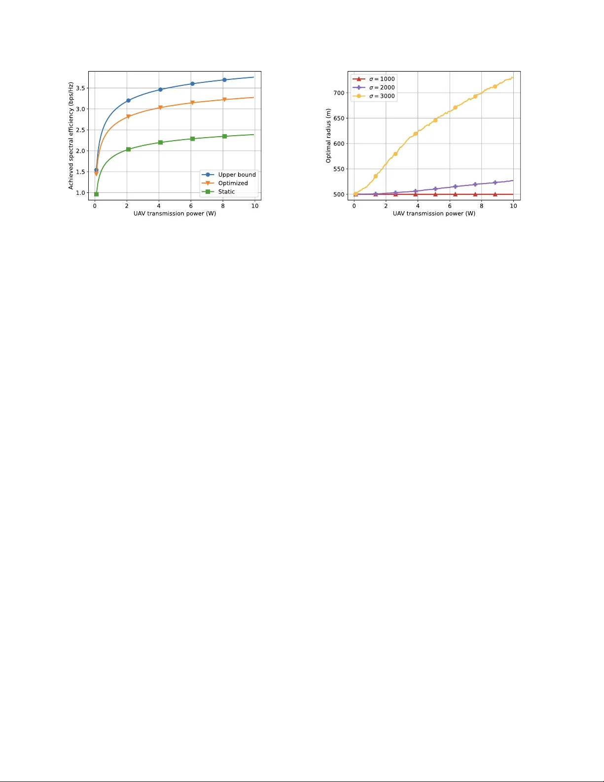
Fix ed-wing U A V relay optimization for co v erage hole reco v ery Daniel T . Bonkowsk y ∗ , Ibrahim Kilinc † , and Robert W . Heath Jr . † ∗ Department of Computer Science and Engineering, Univ ersity of California, San Diego, USA † Department of Electrical and Computer Engineering, Univ ersity of California, San Diego, USA E-mail: { dbonko wsky , ikilinc, rwheathjr } @ucsd.edu © 2026 IEEE. Personal use of this material is permitted. Permission from IEEE must be obtained for all other uses, in any current or future media, including reprinting/republishing this material for advertising or promotional purposes, creating new collective works, for resale or redistribution to servers or lists, or reuse of any copyrighted component of this work in other works. Abstract —Unmanned aerial v ehicles (U A Vs) fill co verage holes as wir eless relays during emergency situations. Fixed-wing U A Vs offer longer flight duration and larger coverage in such situations than rotary-wing counterparts. Maximizing the effectiveness of fixed-wing U A V relay systems requires car eful tuning of system and flight parameters. This process is challenging because factors including flight trajectory , timeshare, and user scheduling are not easily optimized. In this paper , we propose an optimization for U A V -based wireless relaying networks based on a setup which is applicable to arbitrary spatial user positions. In the setup, a fixed-wing U A V flies over a cir cular trajectory and relays data from gr ound users in a coverage hole to a distant base station (BS). Our optimization iterati vely maximizes the average achievable spectral efficiency (SE) for the U A V trajectory , user scheduling, and r elay timeshare. The simulation results show that our optimization is effective for varying user distributions and that it performs especially well on distributions with a high standard deviation. I . I N T R O D U C T I O N U A Vs can be an essential tool for providing cov erage during a disaster when the con ventional cellular infrastruc- ture becomes inoperable. A significant amount of work has considered the role of rotary-wing U A Vs acting as relays between a functioning BS tower and ground-based users [1], [2]. Unfortunately , there is much less work on fixed-wing U A Vs to solve the same challenge. Fix ed-wing U A Vs present a more challenging optimization problem as they have a greater turning radius than rotary-wing U A Vs and must fly abov e a minimum velocity to remain airborne. Fixed-wing U A Vs have benefits of higher flight altitude with larger coverage, longer operation duration, endurance in harsh weather conditions, energy ef ficiency , and payload capacity [1], [3]–[5]. Therefore, fixed-wing U A Vs represent a promising tool as an aerial relay for emergency situations to enable connectivity . In this paper , we consider a fixed-wing U A V relay system for distant users in a coverage hole and propose an optimization to maximize the achiev able spectral efficiency of the system. Relay system optimizations are primarily characterized by the choice of optimization parameters and the setup of the system model. Prior work has demonstrated that system throughput can be maximized by optimizing trajectory [6]– [8], transmission po wer [6], [8], user scheduling [8], [9], and relaying timeshare [10]. A fixed-wing U A V relay in [6] provides a line-of-sight link for edge users in a cell with a BS. Users are, howe ver , assumed to be directly below the circular U A V trajectory . Multiple fixed-wing UA Vs act as relays to aid an ov erloaded BS, serving users located in a ring around the BS in [7]. A fixed-wing U A V in [8] acts as a BS for a mobile group of users, flying with them as they move. A fixed-wing U A V in [9] serves as an aerial BS for users that are assumed to be ev enly spaced along a straight line. A fixed- wing UA V relays between two stationary ground terminals in [10], flying on a constant circular path. In real emergency scenarios, users are distrib uted according to population density , terrain accessibility , and the nature of the disaster, none of which conform to these idealized geometries. The system model in [8] addresses a general distribution of users, but the U A V acts as an aerial BS with a single-hop link from the ground users. Furthermore, the prior work lacks consideration of relay systems [8], [9], and realistic user distributions [6], [7], [10] in cov erage holes. Therefore, our work of optimizing fixed-wing U A V relay systems to support distant coverage holes during emergencies is especially relev ant. W e propose a fixed-wing U A V relay system serving distant users in coverage holes without assuming a specific user distribution. W e de velop an iterati ve optimization to tune circular trajectory , user scheduling, and time allocation to maximize connectivity . The U A V follo ws a circular flight path and uses decode-and-forward relaying between ground users and a stationary BS. The relay system has a slotted communication model in which groups of users are scheduled at each time slot. There is no restriction on the location of the ground users within the co verage dead zone, thus our setup is applicable to arbitrary real-w orld scenarios. Based on this system, we formulate an optimization of the flight trajectory , user scheduling, and relay timeshare, and solve the resulting non-conv ex problem via iterati ve optimization. Through numerical simulation, we e xamine the effects of U A V transmission power , flight altitude, and user distrib ution on the optimization. Results show that the proposed optimization algorithm is resilient to increasing standard deviation of the user distribution, adapts to distribution characteristics, and provides gains over a baseline model. I I . S Y S T E M M O D E L In this section, we describe the network topology of the fixed-wing U A V relay system and slotted communication model. Then, we define the equations used to model signal transmission. x y z ( c x , c y , H ) r ( 0 , 0 , b z ) ( μ x , μ y , 0 ) B a s e s t a t i o n U A V G r o u n d u s e r s GV VB s l o t 1 s l o t 2 s l o t n s l o t N … … GV VB T s (1 - α ) T s αT s Fig. 1. The system and communication model of the UA V -enabled wireless relay system. The UA V flies on a circular trajectory at a fixed altitude and serves users in a distant coverage dead zone by connecting them with a BS located near the origin. W e use a slotted communication model, with multiple users served per time slot. Each time slot is divided between the user-to-U A V link (denoted GV) and U A V -to-BS link (denoted VB). A. Network topology W e consider a wireless system with a fixed-wing UA V relay that serves ground users in a dead zone by connecting them with a distant BS. There is assumed to be no direct connectivity between the users and the BS due to mountains, buildings, or other obstacles that may be present in disasters and emergencies. The U A V relays with a decode-and-forward architecture, and is equipped with a data buf fer large enough to handle data from multiple users. The decoding and re- encoding process is assumed to be instantaneous, and thus the U A V is always either receiving from users or transmitting to the BS. W e only consider one-way relaying from user to U A V to BS, but similar analysis can be applied to relaying in the opposite direction. W e use 3D Cartesian coordinates as a frame of reference, where the origin lies at (0 , 0 , 0) , the xy- plane represents the ground, and the z-axis represents altitude. Fig. 1 shows an ov erview of the proposed system. The physical model of the system is characterized by its three main components: the BS, the ground users, and the U A V . The BS is modeled as a point at the location x B = [0 , 0 , b z ] T . There are G users within the dead zone, which is centered at the location x G = [ µ x , µ y , 0] T . The g th user has coordinates denoted x G g = [ x g , y g , 0] T , which can fall anywhere within the co verage dead zone. The U A V relays between the users and BS from a circular path located at a fixed altitude. W e choose a circular path because it is simple and effecti ve in terms of providing connectivity [2], [6], [11]. The flight path has radius r and center point x c = [ c x , c y , H ] T , where H is constant. W e assume the U A V flies with constant speed v , which is subject to v min < v < v max . Here, v min is the minimum speed of the fix ed-wing U A V required to remain airborne, and v max is determined by the build of the U A V and the radius of the flight path [12]. The communication system is a slotted model, with distinct users served in each time slot. There are N time slots, indexed by n = 1 , . . . , N . Each has length T s , which is short enough that the U A V can be considered stationary over the time slot [13]–[17]. The UA V’ s trajectory can thus be considered a discrete sequence of positions, each one a function of the flight path radius r and the center point of the flight path x c . Then the U A V’ s position during time slot n is giv en as x V n ( r , x c ) = c x + r cos 2 π n N , c y + r sin 2 π n N , H T . (1) While the starting point of the U A V’ s trajectory determines all its subsequent positions, it has negligible impact on the system performance, since we always consider an integer number of rotations. The U A V serves M << G users per time slot using frequency-di vision multiple access [8], [17], and bandwidth is uniformly allocated to ensure fair frequency assignment. T o model user scheduling, we use the binary decision variable 1 ( g , n ) , where B = { 1 ( g , n ) | ∀ n ∈ 1 , . . . , N , ∀ g ∈ 1 , . . . , G } represents all user assignments in ev ery time slot. If user g is served in time slot n , then 1 ( g , n ) = 1 , and otherwise 1 ( g , n ) = 0 . In each time slot, users transmit their data to U A V for the duration T 0 before the U A V forwards this data to the BS for the duration T s − T 0 . W e define α = T 0 /T s as the proportion of each time slot reserved for user-to-U A V transmission, and thus 1 − α is the proportion of each time slot reserved for U A V -to-BS transmission. B. Received signal model Based on the relay model, we deri ve the equations for computing the achiev able rate. W e assume that both the user- to-U A V link (denoted GV) and the UA V -to-BS link (denoted VB) are line-of-sight, and the channels are expressed using a free-space propag ation model [18]. W e assume that Doppler is already corrected as part of carrier frequency of fset estimation. Let the users hav e fixed transmission power P G tx , and let the U A V ha ve transmission power P V tx . Let λ denote the signal wa velength, let Γ T denote the antenna gain at the transmitter , let Γ R denote the antenna gain at the receiver , and let B denote the frequency bandwidth. Let ∥ · ∥ denote the 2 -norm throughout the manuscript. Using free-space propagation, the power of the signal recei ved by the U A V from the g th user in the n th time slot is P V g ,n ( r , x c ) = P G tx Γ T Γ R λ 4 π || x V n − x G g || 2 , and the power of the signal recei ved by the BS in the n th time slot can be expressed as P B n ( r , x c ) = P V tx Γ T Γ R λ 4 π || x V n || 2 . Let N 0 be the noise po wer spectral density . In the user-to- U A V link, there are M users transmitting simultaneously to the U A V with uniform band allocation so the channel for a single user is subject to noise power N 0 B / M . Thus, the signal-to- noise ratio (SNR) of the GV link for the g th user during the n th time slot can be expressed as SNR GV g ,n = P V g,n N 0 B / M and the SNR of the VB link during the n th time slot can be expressed as SNR VB n = P B n N 0 B , where r, x c are omitted for notational con venience. Assuming Gaussian signaling under Gaussian noise, the achiev able spectral efficienc y of the GV link for the g th user during the n th time slot can be expressed SE GV g ,n ( r , x c ) = log 2 (1 + SNR GV g ,n ) [18]. The achie vable spectral efficienc y of the VB link during the n th time slot can be expressed SE VB n ( r , x c ) = log 2 (1 + SNR VB n ) . The performance of the wireless relay system is measured by the average achiev able spectral efficiency per time slot per user. W e define SE GV n ( r , x c , B ) = 1 M P G g =1 1 ( g , n ) SE GV g ,n as av erage per-user spectral efficiency in the GV link. W e assume perfect channel knowledge, and that all users are perfectly synchronized over time slots. Let min( a, b ) be the function of the minimum of a and b . The average achiev able SE of the relay system is giv en as SE ( α, r, x c , B ) = 1 N N X n =1 min α · SE GV n , (1 − α ) · SE VB n . (2) The ar gument of SE ( · ) metric in (2) indicates the optimization variables. All other variables introduced so far are fixed. I I I . P R O B L E M F O R M U L A T I O N The objectiv e is to maximize achiev able SE per-user per- time slot of the relay system expressed in (2). The opti- mization in volv es the variables of timeshare proportion α , the user scheduling set B defined for N time slots, and circular trajectory center x c and radius r . The optimization problem is a non-con vex and non-linear program [19], and optimizing all parameters jointly is not tractable. Instead, we propose an iterative maximization approach by decomposing the problem into timeshare optimization, scheduling optimiza- tion, and trajectory optimization, where each subproblem is better beha ved for optimization. The minimum function in equation (2) is problematic for optimization, since it is non- con ve x and non-dif ferentiable in its arguments [19]. T o address this, we define a lower -bound η n on the achie v able SE in the n th time slot, subject to constraints η n ≤ α SE GV n and η n ≤ (1 − α ) SE VB n , with S = { η n | ∀ n ∈ 1 , . . . , N } defined as the lower -bound on the achiev able spectral efficienc y in each time slot. These constraints allow us to maximize the av erage spectral efficienc y while reformulating each subproblem into an efficiently solvable form. A. T imeshar e optimization The first subproblem in the iterative maximization is to op- timize the timeshare variable α for given trajectory parameters r , x c , and scheduling set B . The problem can be formulated into a linear program giv en as max α, S 1 N N X n =1 η n (3a) subject to η n ≤ α SE GV n , ∀ n (3b) η n ≤ (1 − α ) SE VB n , ∀ n (3c) 0 ≤ α ≤ 1 . (3d) The optimization problem has a linear objecti ve function and affine constraints. Thus, it can be optimized with solvers such as MOSEK, which guarantees solutions that are numerically primal- and dual-feasible [20]. B. Scheduling optimization For a giv en timeshare proportion α and trajectory variables r and x c , the user scheduling set B is optimized using a similar method to timeshare optimization. The binary user-scheduling variables turn the problem into a mixed-inte ger optimization, which is difficult to solve efficiently [21]. T o address this, we relax the binary scheduling v ariables to be continuous, constrained by 0 ≤ ˜ 1 ( g , n ) ≤ 1 , where ˜ B = { ˜ 1 ( g , n ) | ∀ n, u } is the set of all relaxed scheduling variables. W e formulate additional constraints to allo w at most M users to be scheduled in each time slot and each user to be scheduled at most N M G times over all time slots. Then the optimization problem can be written as max ˜ B , S 1 N N X n =1 η n (4a) subject to η n ≤ α SE GV n , ∀ n (4b) η n ≤ (1 − α ) SE VB n , ∀ n (4c) 0 ≤ ˜ 1 ( g , n ) ≤ 1 , ∀ g , n (4d) G X g =1 ˜ 1 ( g , n ) ≤ M , ∀ n (4e) N X n =1 ˜ 1 ( g , n ) ≤ N M G , ∀ g . (4f) The optimization problem is a linear program with a linear ob- jectiv e function and affine constraints, which can be ef ficiently optimized with solv ers such as MOSEK. Upon completion of the scheduling optimization at each iteration, the binary scheduling set B is reconstructed from ˜ B by assigning 1 to the M greatest v alues in each time slot and 0 to the remaining. This process allows an efficient and realistic user scheduling. C. T rajectory optimization The trajectory optimization problem is not directly solvable, since the spectral efficienc y functions SE GV g ,n and SE VB n are non-con ve x with respect to r and x c . T o address this, we employ a successive con vex approximation (SCA) approach [7], [13], [16]. SCA handles non-conv ex optimization prob- lems through an iterative procedure that successiv ely solves tractable subproblems, each obtained by substituting the non- con ve x functions with simpler conv ex surrogates. Let us consider optimizing the non-con ve x function V ( x ) over the con ve x set X using surrogate function ˜ V ( x | x i ) through SCA. The i th iteration of SCA consists of solving a subproblem of the form x i +1 ∈ arg max ˜ V ( x | x i ) , where x i is the solution found during iteration i − 1 . T o guarantee a stable SCA conv ergence, each surrogate function must be continuous on x ∈ X , they must be a global lower -bound of the original function, and the gradient and function v alue at x i must match the original function [22]. T o reformulate trajectory optimization into an SCA prob- lem, it is necessary to construct surrogate functions for SE GV g ,n and SE VB n . T o do this, we first define constants A G = P G tx Γ T Γ R M N 0 B λ 4 π 2 and A B = P V tx Γ T Γ R N 0 B λ 4 π 2 , auxiliary variables d g ,n = || x V n − x G g || 2 and d B n = || x V n || 2 , and sets G = { d g ,n | ∀ g , n } and V = { d B n | ∀ n } . Next, we redefine spectral efficienc y functions SE GV g ,n and SE VB n using these auxiliary variables as SE GV g ,n ( d g ,n ) = log 2 1 + A G d g ,n (5) and SE VB n ( d B n ) = log 2 1 + A B d B n , (6) which are equiv alent to the original SE GV g ,n and SE VB n for any r and x c , and con ve x with respect to d g ,n and d B n . For SCA maximization, it is necessary that surrogate functions are concav e with respect to their parameters, thus, the surrogate functions we propose are the first-order T aylor expansions of SE GV g ,n and SE VB n [19]. This is a reasonable choice, because any conv ex function is globally lower-bounded by its first- order T aylor expansion [19], and because linear functions can be efficiently optimized. Lastly , any equality constraints must be affine for an optimization problem to be con ve x, so the equality constraints on d g ,n and d B n need to be addressed [19]. W e relax the equality constraints on d g ,n and d B n , replacing them with inequality constraints as the upper bounds for the squared user-to-U A V and UA V -to-BS distances. Optimality is preserved under this relaxation, as the maximization of SE GV g ,n and SE VB n inherently minimizes d g ,n and d B n . This ensures the inequality constraints are satisfied as equality at the optimal solution. Thus, the fully formulated subproblem being solved in the i th iteration of SCA can be written as max r, x c , G , V , S 1 N N X n =1 η n (7a) subject to η n ≤ α M G X g =1 1 ( g , n ) · h SE GV g ,n d g ,n ( i ) + SE GV g ,n ′ d g ,n ( i ) d g ,n − d g ,n ( i ) i , ∀ n (7b) η n ≤ (1 − α ) · h SE VB n d B n ( i ) + SE VB n ′ d B n ( i ) d B n − d B n ( i ) i , ∀ n (7c) d g ,n ≥ || x V n − x G g || 2 , ∀ g , n (7d) d B n ≥ || x V n || 2 , ∀ n, (7e) where d g ,n ( i ) and d B n ( i ) are the values of d g ,n and d B n found from the ( i − 1) th SCA iteration. The objectiv e function is linear , constraints (7b) and (7c) are affine, and constraints (7d) and (7e) are con vex. Therefore, the problem solved during each iteration is a con ve x optimization problem, which can be efficiently solved with guarantees as described in the timeshare optimization subsection. Our formulation leads to a stable con ver gence because d g ,n and d B n are bounded from below , so cannot be arbitrarily small. V alues for d g ,n and d B n also cannot be arbitrarily large, since SE GV g ,n and SE VB n are decreasing over d g ,n and d B n . Fig. 2. Impact of the standard deviation of the user distribution on the achiev ed SE of the system. The upper bound performs well regardless of standard deviation, because it is optimized per-user . Comparing the optimized model with the static model, which represents a reasonable heuristic, shows that our optimization is more robust to standard deviation increases. I V . N U M E R I C A L R E S U LT S In this section, we present numerical results by focusing on a specific network topology . The simulation in volv es G = 20 ground users, with M = 2 users served concurrently per time slot. A complete flight path traversal is divided into N = 500 time slots. The UA V maintains a circular trajectory at an alti- tude of H = 1000 m with a minimum radius of r min = 500 m. The user transmission power is set to P G tx = 0 . 01 W [23], and the U A V transmission po wer is set to P V tx = 10 W [24] unless stated otherwise. The spatial user distribution follo ws a biv ariate normal distribution with means µ x , µ y and standard deviations σ x , σ y , following prior work that has shown this to be a realistic model for user hotspots [25]. T o ev aluate our optimization, we compare its performance against two baselines: an ideal upper bound and a static, heuristic-based model. The upper bound represents the av erage SE achie ved by a rotary-wing U A V serving users in a round- robin fashion. For each user, it hovers at the optimal location with optimal timeshare, optimized by the methods described in Sec. III. It represents an unattainable upper-bound in practice since the rotary-wing U A V cannot hover instantaneously at each time slot. The static baseline uses random user scheduling and a fixed circular trajectory centered at x c = [ µ x , µ y , H ] T with r = r min . T o calculate the relay timeshare α for the static baseline, we model the distribution as a single user located at the center of the dead zone, and the U A V as a stationary relay located at x c . Let SE 1 be the spectral ef ficiency of the single user -to-relay link, and let SE 2 be the spectral efficienc y of the relay-to-BS link. The optimal relay timeshare for the static baseline can be calculated as α = SE 2 SE 1 + SE 2 [26]. Prior work either does not address scenarios with varying user distributions [6], [7], [10] or does not consider relay systems [8], [9], which makes direct comparison challenging. Fig. 3. The effect of UA V transmission power on the SE achieved in the system. As U A V transmission power increases, the throughput bottleneck becomes the transmission power of the users, and the achiev able spectral efficienc y le vels off. The static model cannot adapt to utilize the increase in U A V transmission power and lev els very quickly . The optimized model can take advantage of increased transmission power by flying closer to users, mitigating the user-to-U A V limitation. Nev ertheless, we adapt the rotary-wing approach from prior work to establish a meaningful upper-bound baseline and employ the optimal timeshare strategy from [26] as a static baseline for our setting. A. Impact of variance on spectral efficiency The plot in Fig. 2 shows the impact of user variance on the spectral efficienc y achiev ed by the system for two baselines and our method. The plots were generated using 3000 Monte Carlo runs. The results sho w that with increasing standard deviation, the upper bound is unchanged, while the optimized and static trajectory suffer spectral ef ficiency losses. The upper bound is optimized per-user , so it is expected that increasing the spread of users has little effect on ov erall SE. Comparing our approach with the static baseline shows the efficacy of our optimization. As users become more spread out, the U A V can respond and alter its trajectory to serve users better . Accordingly , the optimized system has a smaller decrease in spectral efficiency performance than the static system as the standard deviation increases. Consequently , our optimization becomes more relev ant as the users are more spread out. B. Impact of UA V transmission power on spectral efficiency Fig. 3 illustrates the effect that U A V transmission po wer has on the SE. Increasing U A V transmission power yields signifi- cant SE gains initially; howe ver , the performance subsequently saturates, which re veals the inherent bottleneck of wireless relay systems. T otal throughput is giv en by the minimum of the user-to-U A V and UA V -to-BS links, so ev en a system with a powerful UA V transmitter will perform poorly if user transmission po wer is weak. The optimized trajectory performs much better than static baseline, especially for greater UA V transmission power . This demonstrates the flexibility of our Fig. 4. Impact of the UA V transmission power on the optimized radius. Optimal radius is positi vely correlated with transmission power , because greater transmission power gives the UA V more freedom to trav el far from the BS and closer to ground users. This freedom is more pronounced in distributions with a larger standard de viation, because a larger radius is required to serve users when their spread is greater . optimization, that is able to use high transmission power to achiev e SE gains over the static baseline. C. Impact of UA V transmission power on optimal radius Next, we consider how the U A V’ s transmission power affects the optimal radius of the flight path. W e present results for user distrib utions with standard deviations σ x = σ y = 1000m, 2000m, and 3000m. Fig. 4 demonstrates that as U A V transmission power increases, the optimal flight path radius increases with it. For a U A V with greater transmission power , it is optimal to fly further from the BS and closer to ground users, who ha ve a weaker transmission power . For distrib utions with a larger standard deviation, flying closer to users requires a larger radius, while distributions with a small standard deviation can be effecti vely served by a U A V circling with a small radius. The optimal radius jump between σ = 2000 and 3000 m occurs when a verage user distance exceeds flight altitude. At this threshold, the U A V prioritizes flying closer to users rather than maintaining altitude to maximize throughput. D. Impact of height and distance on spectral efficiency gain Lastly , we examine the joint effect of UA V height and user distance on SE gain. W e define SE gain as the SE difference between the SE achiev ed by our solution and the static baseline, a metric we use to measure when our optimization is most useful. The heatmap in Fig. 5 measures SE gain relativ e to the flight altitude and the mean of the user distrib ution, with standard deviation fixed at σ x = σ y = 2000m. The results show that the SE gain is highly correlated with flight altitude, b ut largely independent of the distrib ution’ s mean. This independence occurs because both models account for user distance similarly via timeshare biasing. In contrast, altitude has a large impact on SE gain. At high altitudes, the user distribution appears as a point source, making the effects of variance and hotspots negligible. At low altitudes, Fig. 5. SE gain of a system with optimized parameters over a system with static parameters relativ e to the height of the UA V and the distance of the users from the BS. Flight altitude is highly correlated with SE gain because variance is increasingly impactful at lower altitudes. User distance is less so because both optimized and static models are able to account for it with timesharing. our optimization provides significant gains by adapting flight parameters to mitigate variance. V . C O N C L U S I O N S Fixed-wing UA Vs can provide quick and effecti ve solution for disrupted connecti vity ov er a cov erage hole during disasters and emergencies. In this paper , we proposed an achie vable spectral ef ficiency optimization for a fixed-wing U A V relay on a circular trajectory that connects ground users to a distant BS. W e showed that a fixed-wing UA V relay with circular trajec- tory can pro vide an achie vable SE close to that of an unattain- able upper-bound. Moreover , optimizing timeshare, trajectory , and user scheduling introduces a substantial achiev able SE improv ement compared to a heuristic model. Furthermore, the optimization is able to outperform the heuristic model as standard de viation increases, and does especially well at low altitudes. Lastly , the U A V transmission power is positi vely correlated with the optimal flight radius in the cases with greater standard de viation of users. Therefore, higher U A V transmission power for distant users is more beneficial for larger coverage holes with more user de viation. Future work will focus on extending this model to handle more advanced trajectories, and consider the benefits and challenges of using multiple U A Vs in the relaying system. R E F E R E N C E S [1] Y . Zeng, R. Zhang, and T . J. Lim, “W ireless communication with un- manned aerial vehicles: Opportunities and challenges, ” IEEE Commun. Mag. , vol. 54, no. 5, pp. 36–42, 2016. [2] S. M. Abohashish, R. Y . Rizk, and E. Elsedimy , “Trajectory optimization for U A V-assisted relay over 5G networks based on reinforcement learning framework, ” EURASIP J. on W ireless Commun. and Netw . , vol. 2023, no. 1, p. 55, 2023. [3] A. Filippone, Flight performance of fixed and rotary wing air craft , ser . Elsevier Aerospace Engineering. Butterworth-Heinemann, 2006. [Online]. A vailable: https://books.google.com/books?id=lTkiuG4RaFIC [4] M. Gatti, F . Giulietti, and M. T urci, “Maximum endurance for battery- powered rotary-wing aircraft, ” Aer ospace Sci. and T echnol. , vol. 45, pp. 174–179, 2015. [5] V . Mayor, R. Estepa, A. Estepa, and G. Madinabeitia, “Deploying a reliable UA V-aided communication service in disaster areas, ” W ireless Commun. and Mobile Comput. , v ol. 2019, no. 1, p. 7521513, 2019. [6] X. Chenxiao and X.-L. Huang, “Energy-efficiency maximization for fixed-wing UA V-enabled relay network with circular trajectory , ” Chin. J. of Aer onaut. , v ol. 35, no. 9, pp. 71–80, 2022. [7] A. V isintini, T . D. P . Perera, and D. N. K. Jayakody , “3-D trajectory op- timization for fixed-wing U A V-enabled wireless network, ” IEEE Access , vol. 9, pp. 35 045–35 056, 2021. [8] X. Y an, X. Fang, C. Deng, and X. W ang, “Joint optimization of resource allocation and trajectory control for mobile group users in fixed- wing U A V-enabled wireless netw ork, ” IEEE T rans. W ir eless Commun. , vol. 23, no. 2, pp. 1608–1621, 2023. [9] J. L yu, Y . Zeng, and R. Zhang, “Cyclical multiple access in UA V-aided communications: A throughput-delay tradeoff, ” IEEE T rans. W ireless Commun. , v ol. 5, no. 6, pp. 600–603, 2016. [10] F . Ono, H. Ochiai, and R. Miura, “ A wireless relay network based on unmanned aircraft system with rate optimization, ” IEEE Tr ans. W ireless Commun. , v ol. 15, no. 11, pp. 7699–7708, 2016. [11] W . W ang, X. Guan, B. W ang, and Y . W ang, “ A novel mobility model based on semi-random circular mov ement in mobile ad hoc networks, ” Information Sci. , vol. 180, no. 3, pp. 399–413, 2010. [12] P . Panagiotou and K. Y akinthos, “ Aerodynamic efficiency and perfor- mance enhancement of fixed-wing U A Vs, ” Aer ospace Sci. and T echnol. , vol. 99, p. 105575, 2020. [13] Q. Wu, Y . Zeng, and R. Zhang, “Joint trajectory and communication design for multi-UA V enabled wireless networks, ” IEEE T rans. on W ireless Commun. , vol. 17, no. 3, pp. 2109–2121, 2018. [14] T . Liu, M. Cui, G. Zhang, Q. Wu, X. Chu, and J. Zhang, “3D trajectory and transmit power optimization for UA V-enabled multi-link relaying systems, ” IEEE T rans. Green Commun. Netw . , vol. 5, no. 1, pp. 392– 405, 2020. [15] C. Qiu, Z. W ei, Z. Feng, and P . Zhang, “Backhaul-aware trajectory optimization of fixed-wing UA V-mounted base station for continuous av ailable wireless service, ” IEEE Access , vol. 8, pp. 60 940–60 950, 2020. [16] B. Li, R. Zhang, and L. Y ang, “Joint user scheduling and UA V trajectory optimization for full-duplex UA V relaying, ” in Pr oc. IEEE Int. Conf. Commun. (ICC) . IEEE, 2021, pp. 1–6. [17] Y . Sun, D. Xu, D. W . K. Ng, L. Dai, and R. Schober , “Optimal 3D-trajectory design and resource allocation for solar-po wered U A V communication systems, ” IEEE T rans. on Commun. , vol. 67, no. 6, pp. 4281–4298, 2019. [18] R. W . Heath and A. Lozano, F oundations of MIMO communication . Cambridge Uni versity Press, 2018. [19] S. P . Boyd and L. V andenberghe, Conve x optimization . Cambridge Univ ersity Press, 2004. [20] MOSEK ApS, MOSEK optimizer API for python, r elease 11.0.28 , Copenhagen, Denmark, Aug. 2025, available at https://docs.mosek.com/11.0/pythonapi/index.html. [21] M. Lubin, “Mixed-integer con vex optimization: outer approximation algorithms and modeling power , ” Ph.D. dissertation, Massachusetts Institute of T echnology , 2017. [22] G. Scutari and Y . Sun, “Parallel and distributed successive con vex approximation methods for big-data optimization, ” in Multi-Agent Op- timization , ser. Lecture Notes in Mathematics, F . Facchinei and J.-S. Pang, Eds. Cham, Switzerland: Springer , 2018, pp. 141–308. [23] X. Li, D. Guo, H. Y in, and G. W ei, “Drone-assisted public safety wireless broadband network, ” in Proc. IEEE WCNCW . IEEE, 2015, pp. 323–328. [24] Qualcomm T echnologies, Inc., “L TE unmanned aircraft systems: T rial report, v1.0.1, ” Qualcomm T echnologies, Inc., San Diego, California, T ech. Rep., May 2017. [25] C. Saha, M. Afshang, and H. S. Dhillon, “Enriched k -tier hetnet model to enable the analysis of user-centric small cell deployments, ” IEEE T rans. W ireless Commun. , vol. 16, no. 3, pp. 1593–1608, 2017. [26] S. W . Peters, A. Y . Panah, K. T . Truong, and R. W . Heath, “Relay architectures for 3GPP L TE-Advanced, ” EURASIP J. W ir eless Commun. Netw . , v ol. 2009, no. 1, p. 618787, Dec. 2009.
Original Paper
Loading high-quality paper...
Comments & Academic Discussion
Loading comments...
Leave a Comment