Dominant Transient Stability of the Co-located PLL-Based Grid-Following Renewable Plant and Synchronous Condenser Systems
Deploying synchronous condensers (SynCons) near grid-following renewable energy sources (GFLRs) is an effective and increasingly adopted strategy for grid support. However, the potential transient instability risks in such configurations remain an op…
Authors: Bingfang Li, Songhao Yang, Qinglan Wang
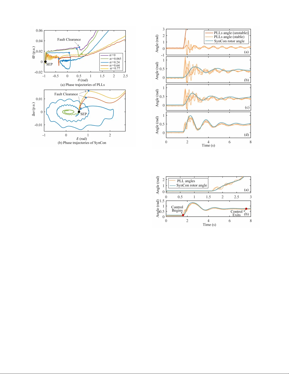
1 Dominant T ransient Stability of the Co-located PLL-Based Grid-F ollo wing Rene wable Plant and Synchronous Condenser Systems Bingfang Li, Member , IEEE , Songhao Y ang, Senior Member , IEEE , Qinglan W ang, Xu Zhang, Graduate Student Member , IEEE , Huan Xie, Chuan Qin, Zhiguo Hao, Senior Member , IEEE Abstract —Deploying synchronous condensers (SynCons) near grid-follo wing r enewable ener gy sour ces (GFLRs) is an effective and increasingly adopted strategy f or grid support. Howev er , the potential transient instability risks in such configurations r emain an open resear ch question. This study in vestigates the mechanism of dominant synchronization instability sour ce transition upon SynCon integration and proposes a straightforward approach to enhance system stability by leveraging their interactive charac- teristics. Firstly , a dual-timescale decoupling model is established, partitioning the system into a fast subsystem representing phase- locked loop (PLL) dynamics and a slow subsystem characterizing SynCon rotor dynamics. The study then examines the influence of SynCons on the transient stability of nearby PLLs and their own inherent stability . The study shows that SynCon’s voltage-source characteristics and its time-scale separation from PLL dynamics can significantly enhance the PLL ’s stability boundary and mitigate non-coherent coupling effects among multiple GFLRs. Howev er , the dominant instability sour ce shifts from the fast- time-scale PLL to the slow-time-scale SynCon after SynCon integration. Crucially , this paper demonstrates that the damping effect of PLL control can also be transferred from the fast to the slow time scale, allowing well-tuned PLL damping to suppress SynCon rotor acceleration. Consequently , by utilizing SynCon’s inherent support capability and a simple PLL damping loop, the transient stability of the co-located system can be significantly enhanced. These conclusions are validated using a converter controller -based Hardware-in-the-Loop (CHIL) platform. Index T erms —transient stability , synchronous condenser , grid- follo wing con verter , dual time scale, damping contr ol N O M E N C L A T U R E δ Rotor angle of SynCon relati ve to the grid. θ i Output angle of the i -th PLL relativ e to the grid. ω s , ω ci , ω g Angular frequency of the SynCon, the i -th con verter , the grid. ∆ ω , ϖ ci Angular frequency of SynCon and the i -th con verter relati ve to the grid. E s ∠ δ Electric potential of the SynCon. U ci ∠ ϕ ci V oltage phasor of the i -th conv erter . U g ∠ 0 ◦ V oltage phasor of the grid bus. This work was supported by the K ey Research and De velopment Program of Shaanxi (2025PT -ZCK-01). The authors acknowledge J. Guo from the Shaanxi Ke y Laboratory of Smart Grid for providing access to the instruments that supported this work. B. Li, S. Y ang, Q. W ang, X. Zhang, and Z. Hao are with Xi’an Jiaotong Univ ersity , Xi’an 710049, China (e-mail: libingfang@stu.xjtu.edu.cn; song- haoyang@xjtu.edu.cn; zhghao@xjtu.edu.cn). H. Xie and C. Qin are with State Grid Jibei Electric Po wer Co., Beijing 100000, China. I ci ∠ φ ci Current phasor of the i -th con verter . I s ∠ φ ci Current phasor of the SynCon. L ci , L s , L g GFLR, SynCon, and grid-side branch induc- tance. R ci , R s , R g GFLR, SynCon, and grid-side branch resis- tance. Y ci , Y s , Y g GFLR, SynCon, and grid-side branch admit- tance. α Coupling coefficient of GFLR and SynCon, defined as Y s / ( Y s + Y g ) . d i − q i Rotating reference frame of the i -th con verter . d s − q s Rotating reference frame of the SynCon. x − y Rotating reference frame of the grid. k P i , k I i Proportional, integral gain of the i -th PLL. i drf ci , i q rf ci Activ e, reactive current references of the i -th con verter . i d ci , i q ci Activ e and reactiv e current of the i -th con- verter . P E Real electromagnetic power of SynCon. T s Inertia time constant of the SynCon. D s Damping coefficient of the SynCon. P c Equiv alent mechanical po wer of the SynCon. P es Equiv alent electromagnetic po wer of SynCon. u q ci The q i -axis component of U ci ∠ ϕ ci . i d i cij The sum of the d i -axis components of the currents from all other con verters. T ci Equiv alent time constant of the i -th PLL. P M ci , P E ci Equiv alent mechanical power , equiv alent elec- tromagnetic power of the i -th PLL. D ci Equiv alent damping coefficient of the i -th PLL with respect to the synchronous grid. D cij Equiv alent damping term of the i -th PLL with respect to other PLLs. t, τ Slow , fast time scale time variable. ε Small parameter for time scale separation. δ Frozen value of δ on fast time scale. i d i ∗ cij The d i -axis component of the currents from other con verters under coherent condition. U E An equiv alent voltage after SynCon integra- tion. θ δ Arctan term of the SEP angle θ ∗ si . θ bi The stability index for the i -th PLL. θ ′ i T ransformed phase angle, defined as θ i − θ δ . P ∗ M ci Equiv alent mechanical power of the i -th con- 2 verter under multi-con verter coherent opera- tion. ∆ P M ci Defined as P M ci − P ∗ M ci . D ∗ ci Damping coef ficient of the i -th con verter under multi-con verter coherent operation. ∆ D ci Defined as D ci − D ∗ ci . u i Non-coherent disturbance term. u max i , u min i Maximum, minimum non-coherent distur- bance term of the i -th con verter . I max cj Maximum allow able current for the j -th GFLC. V ci , ˙ V ci T ransient energy function and its time deriv a- tiv e of the i -th conv erter . θ ∗ si SEP angle of the i -th con verter . η ci Power factor angle of the i -th con verter cur- rent, defined as θ i − φ ci . i d s c Sum of the projections of each GFLC current onto the d s -axis. ∆ δ Change in the δ during a small time interval ∆ t . ∆ θ i Change in the angle θ i of the i -th con v erter during a small time interv al ∆ t . t 0 , t 1 Instants post-PLL synchronization and during δ acceleration in the first swing after t 0 . t f Estimated fault duration time. K d Additional Damping loop coefficient of PLL. I . I N T RO D U C T I O N R Enew able energy sources, such as wind and solar power , are undergoing rapid growth. Most of these resources are integrated into the grid through grid-following con verters (GFLCs) for grid connection [1]. Howe ver , GFLCs possess inherent limitations, including restricted grid-support capabili- ties and susceptibility to tripping under disturbances [2]. Since large-scale renew able generation is often located remotely from load centers, these plants typically serve as sending-end systems. The transmission of bulk power over long electrical distances inherently weakens the A C grid connection. This fragility exacerbates stability risks, contributing to wide-band oscillations, violations of frequency and voltage limits, and, in extreme cases, large-scale blackouts [3], [4]. Against this backdrop, there is a growing need for rene wable generation facilities to dev elop grid-supporting capabilities. T wo main approaches ha ve emerged as promising solutions. The first approach is introducing grid-forming (GFM) control, which is predominantly based on the concept of the virtual synchronous generators (VSGs) [5]. VSGs emulate the inertial response and damping characteristics of synchronous genera- tors (SGs), thus providing essential grid-support services [6]. Nev ertheless, due to the inherently lo w o vercurrent capability of power electronic devices, GFM units are susceptible to entering current-limiting mode during transients [7]. This not only constrains their ability to support the grid but also introduces more complex stability challenges. The second approach in v olves combining grid-following renew able energy sources (GFLRs) with synchronous con- densers (SynCons). This solution has been discussed in [8], and many studies hav e shown that such configuration can mitigate transient overv oltage and frequency violations, while reducing the risk of wide-band oscillations in renew able energy systems [3], [9]–[11]. Moreover , SynCons offer a significant advantage over power -electronic-based de vices in their superior ov ercurrent withstand capability , enabling them to maintain a voltage source characteristic e ven during se vere system disturbances. Globally , this configuration is being acti vely planned and adopted in sev eral countries. Energinet, the transmission sys- tem operator (TSO) of Denmark, has emphasized the value of SynCons in improving system stability and deliv ering ancillary services [9]. Nordic TSOs like wise recognize that adding rotating inertia from SynCons can help address the low-inertia challenge [9]. The State Grid Corporation of China (SGCC) has explicitly advocated for the deployment of SynCons at renew able energy sites to bolster short-circuit capacity support in its national grid de velopment plans. [12]. In practice, distributed SynCons have been deployed and put into operation at several renew able energy facilities across China [13], [14]. Operational data indicate that their integration has increased renew able output from approximately 30% to more than 70% of installed capacity [14]. Similar applications have also been reported in the United States, where SynCons have been used to enhance voltage, frequency , and reacti ve power support [15]. These experiences collectiv ely suggest that the “GFLR+SynCon” configuration is a promising solution for strengthening current and future po wer system architectures. In con ventional understanding, SynCons, as reactive com- pensation devices without prime movers, appear to be at little risk of transient acceleration issues like those in SGs. They are only likely to experience decelerating instability when located at load centers [16]. Howe ver , as noted in [17] and [18], the GFLR output can be equi valently regarded as the mechanical power input to the SynCon, thereby providing the impetus for angle acceleration. In addition, refs. [17] and [19] examine the influence of dif ferent fault types and low- voltage ride-through (L VR T) strategies on SynCon instability modes and transient energy accumulation. Their findings in- dicate that, under certain conditions, SynCons may exhibit an unusual instability pattern, decelerating during short circuits and subsequently undergoing acceleration instability after fault clearance. These inv estigations primarily address the stability of supporting devices within GFLR grid connected systems, leaving two critical issues that merit further exploration: First, phase-locked loops (PLLs) in GFLC are widely rec- ognized for their inherent fragility , particularly during v oltage disturbances [20]–[23]. Considering the recent occurrences of instability in synchronous condensers, what is the dominant transient instability issue: the PLL or the SynCon? Second, how should SynCon instability be ef fectiv ely ad- dressed? The most straightforward option is to trip SynCons or a portion of GFLRs. Howe ver , this compromises the structural integrity of the network and, furthermore, tripping these units may trigger a secondary large disturbance. Enhancing SynCon stability through excitation control [24] faces limitations, par- ticularly in adapting to time-varying disturbances from nearby GFLRs. A potentially more fundamental solution is to target 3 GFLR output, the root cause of SynCon instability . This con- cept has been in v estigated in [19], where system frequency and output power are measured in real time and fed back to GFLR plants for output adjustment. Ne v ertheless, significant practical challenges remain. These include the intricate coordination of multiple GFLR units with diverse operating states, and the imperativ e of maintaining energy balance and DC link voltage stability following output adjustments. T o answer these questions, this study in vestigates the impact mechanism of SynCon integration on the transient stability of the original GFLC system, and the transfer mechanism of the system’ s dominant transient instability source. Furthermore, it proposes a practical method for stability enhancement. The main contributions are as follows: 1) This study dev elops a dual time-scale transient stability analysis model, separating the system into a fast subsys- tem (representing PLL dynamics) and a slow subsystem (representing SynCon rotor dynamics). This framew ork provides a clear basis for analyzing the impact mecha- nism of SynCon integration on system stability . 2) This study reveals the mechanism by which the system’ s dominant instability source changes after SynCon inte- gration. The SynCon’ s voltage-source characteristics and the decoupling of its rotor dynamics from PLL dynamics significantly enhance the transient stability of GFLC- based systems and mitigate non-coherent inter-con v erter coupling effects. Ho wev er , the primary instability source transitions from the GFLR’ s PLL to the SynCon. 3) This study reveals that well-tuned PLL damping control is capable of damping the rotor acceleration of the SynCon. Building on this finding, it offers a simple and practical engineering approach for enhancing dual-time- scale transient stability . I I . S Y S T E M M O D E L I N G A. System Overview As sho wn in Fig. 1, the studied power system consists of GFLCs and a SynCon connected at the point of common coupling (PCC). The PCC is linked to the remote grid bus via transformers and transmission lines. The co-located system includes multiple con verters, which, after aggregation at the same b us and subsequent aggregation of coherent con verters across different buses, can be represented by n aggregated parallel con verter units [23]. The electric potential of the SynCon is denoted by E s ∠ δ . The voltages at the outlet bus of the i -th aggregated conv erter unit (hereafter referred to as the i -th con verter), and the grid bus are represented by U ci ∠ ϕ ci ( i = 1 , 2 , . . . , n ) and U g ∠ 0 ◦ , respecti vely . The angular speeds of the PLL of the i -th con verter , SynCon’ s rotor , and the grid bus are denoted as ω ci , ω s , and ω g . I ci ∠ φ ci and I s ∠ φ s are the brunch currents. R ci , R s , R g are the branch resistances, and L ci , L s , L g are the branch inductance. The admittance of these branches are denoted as Y ci , Y s , and Y g . As depicted in Fig. 2, the d i − q i , d s − q s , and x − y reference frames are the rotating reference frames of the i -th con verter , the SynCon, and the grid bus, respectively. These Fig. 1. T opology of the co-located GFLR and SynCon System. Fig. 2. Relationships of different frames in vector space. Fig. 3. Control structure and time scale di vision of the GFLR-SynCon system. frames rotate counterclockwise at angular speeds of ω ci , ω s , and ω g , respectiv ely . The d s -axis leads the x -axis by an angle δ , representing the rotor angle of the SynCon relativ e to the grid bus. The d i -axis leads the x -axis by an angle θ i . The i − th GFLC adopts the classic cascaded control structure sho wn in Fig. 3. Under normal operation, the ref- erences for the acti ve and reacti ve currents, i drf ci and i q rf ci , are determined by the outer control loop. During L VR T and its recovery period, these references are directly set by the L VR T control strategy . Since variations in i drf ci and i q rf ci are approximately decoupled from the PLL dynamics, they are treated as parameters rather than state variables in the PLL stability analysis [21], [25]. Furthermore, the inner current control loop exhibits significantly faster dynamics (hundreds of Hz) compared to the PLL dynamics (tens of Hz) [21]. Thus, when analyzing PLL transient stability , it is reasonable to as- sume that GFLC currents accurately track their references, i.e., i d ci = i drf ci and i q ci = i q rf ci [21], [22]. Here, i d ci and i q ci denote the acti ve and reacti v e currents of the i -th con v erter , which also satisfy i d ci = I ci cos( θ i − φ ci ) and i q ci = − I ci sin( θ i − φ ci ) . These relationships are shown in Fig. 2. 4 B. Dynamic Model of SynCon W ithout a prime mover , SynCon’ s real mechanical power is approximately zero. Its rotor dynamic equation is dδ dt = ω s − ω g = ω g ∆ ω , d ∆ ω dt = 1 T s (0 − P E − D s ∆ ω ) , (1) where P E , T s , and D s are the mechanical power , electromag- netic po wer , inertia time constant, and damping coef ficient of SynCon, respectiv ely. The electromagnetic power of the SynCon, P E , can be deriv ed from its definition as: P E = Re ( E s ∠ δ · I s ∠ − φ s ) = E s U g α | Y g | sin δ | {z } P es − αE s n X i =1 I ci cos ( δ − φ ci ) | {z } P c , (2) where P c denotes the power coupling term between the GFLR and the SynCon; P es represents the electromagnetic po wer of the SynCon in the absence of any influence from the GFLR; α is a coupling coefficient, which depends solely on the network topology parameters: α = Y s Y s + Y g . (3) Neglecting the network resistance [25], [26] allows α to be a real number . C. Dynamic Model of PLLs The dynamic equations of the i -th con v erter’ s PLL (here- after referred to as the i -th PLL) are provided as: dθ i dt = ω ci − ω g = ϖ i , dϖ i dt = k I i u q ci + k P i du q ci dt , (4) where ϖ i = ω ci − ω g denotes the deviation of the output angular frequency of the i -th PLL from the synchronous angular frequency. u q ci is the q i -axis component of U ci ∠ ϕ ci . k I i and k P i are the integral and proportional gains of the i -th PLL, respectiv ely . After the grid connection of the SynCon, u q ci can be expressed as: u q ci = − αE s sin( θ i − δ ) − (1 − α ) U g sin θ i + ( ϖ i + ω g ) [ L ci + (1 − α ) L g ] i d ci + ( ϖ i + ω g )(1 − α ) L g i d i cij , (5) where i d i cij is the sum of the d i -axis components of the currents from all other conv erters ( j = i ). Its expression is giv en as: i d i cij = n X j =1 ,j = i I cj cos( θ i − φ j ) . (6) By substituting (5) and its time deriv ativ e into (4), the PLL ’ s dynamic equation after SynCon grid integration is as follo ws: d 2 θ i dt 2 = dϖ i dt = 1 T ci ( P M ci − P E ci − D ci ϖ i − D cij ) , (7) where T ci , P M ci , P E ci , D ci , and D cij denote the equi valent dynamic time constant, the equi valent mechanical power , equiv alent electromagnetic power , equiv alent damping coef- ficient with respect to the synchronous grid, and equiv alent damping term with respect to other PLLs of the i -th PLL, respectiv ely. Their expressions are giv en as follows: P E ci = αE s sin( θ i − δ ) + (1 − α ) U g sin θ i , (8) P M ci = ω g [ L ci + (1 − α ) L g ] i d ci + ω g (1 − α ) L g i d i cij , (9) D ci = k P i k I i [ αE s cos( θ i − δ ) + (1 − α ) U g cos θ i ] − [ L ci + (1 − α ) L g ] i d ci − (1 − α ) L g i d i cij , (10) D cij = k P i k I i ω g (1 − α ) L g n X j =1 ,j = i I cj sin( θ i − φ j )( ϖ i − ϖ j ) , (11) T ci = 1 k I i n 1 − k P i h ( L ci + (1 − α ) L g ) i d ci + (1 − α ) L g i d i cij io . (12) D. Singular P erturbation Model of the co-located System Due to the significant difference in time scales between the rotor dynamics of the SynCon and the control response of the PLLs [27], their ov erall dynamic behavior exhibits a dual time-scale characteristic. By introducing the dimensionless parameter: ε = T ci T s = 1 − k P i h ( L ci + (1 − α ) L g ) i d ci + (1 − α ) L g i d i cij i k I i T s , (13) the original model of the co-located GFLR and SynCon system can be decoupled into two subsystems. They are a slow subsystem associated with the rotor dynamics of the SynCon, and a fast subsystem associated with the dynamics of the PLL: Slow subsystem: dδ dt = ∆ ω , T s d ∆ ω dt = P c − P es − D s ∆ ω , 0 = P M ci − P E ci . (14) Fast subsystem: dδ dτ = 0 , d ∆ ω dτ = 0 , dθ i dτ = εϖ i , dϖ i dτ = 1 T s ( P M ci − P E ci − D ci ϖ i − D cij ) . (15) where τ = t/ε . Based on singular perturbation theory [28], when analyzing the fast subsystem’ s stability , the slow sub- system’ s state variables are considered “frozen” (or quasi- steady). Con versely , when inv estigating the stability of the slow subsystem, the fast subsystem is assumed to ha ve reached its steady state (or to hav e become unstable). 5 I I I . M E C H A N I S M O F I N S TA B I L I T Y S O U R C E T R A N S F E R I N D U C E D B Y S Y N C O N I N T E G R AT I O N This section elucidates the impact mechanism of SynCon integration on system stability by analyzing its role in fast- time-scale stability and its own slow-time-scale dynamics. Consequently , it reveals how the dominant instability source transitions from the fast to the slo w time scale. A. SynCon’s Role in Enhancing F ast T ime-Scale Coherent PLLs Stability Let the superscript “ ∗ ” denote the value of a variable of the i -th conv erter under the condition that all aggregated parallel con verter units operate coherently . For example, i d i ∗ cij repre- sents the d i -axis component of the currents from other con vert- ers ( j = i ) under coherent condition. Accordingly , P ∗ M ci and D ∗ ci represent, respecti vely , the equiv alent mechanical power and the damping coef ficient with respect to the synchronous grid, both under coherent condition. The coherent-operation case is regarded as the nominal system of the i -th conv erter , as giv en in (16): d 2 θ i dt 2 = dϖ i dt = 1 T ci f i θ i , δ , (16) where δ is the frozen value of δ in the fast time scale, and f θ i , δ = P ∗ M ci − P E ci − D ∗ ci ϖ i . (17) The angle at the stable equilibrium point (SEP) of the i -th PLL, denoted by θ ∗ si , can be expressed as: θ ∗ si = arcsin P ∗ M ci U E + arctan αE s sin δ αE s cos δ + (1 − α ) U g | {z } θ δ , (18) where the arctan term of θ ∗ si is denoted as θ δ , and the expression for U E is giv en by: U E = q α 2 E 2 s + (1 − α ) 2 U 2 g + 2 α (1 − α ) E s U g cos δ . (19) It follows that U E can be regarded as an equiv alent v oltage established after the SynCon is connected to the grid. If α = 0 (i.e., SynCon not integrated), U E = U g . Previous studies have sho wn that the range of θ for which the damping coefficient is positive defines the PLL ’ s con- servati v e stability boundary [21], [30]. For D ∗ ci > 0 , the conservati v e stability boundary of the i -th PLL is gi ven by: θ δ − θ bi < θ i < θ δ + θ bi , (20) where θ bi = arccos k I i P ∗ M ci k P i ω g U E . (21) By applying a coordinate transformation θ ′ i = θ i − θ δ , the original boundary in (20) is shifted to the symmetric form − θ bi < θ ′ i < θ bi . This translation does not affect the system’ s intrinsic dynamics, because the governing differential equa- tions remain inv ariant under constant shifts of state variables [29]. In this transformed system, θ bi in directly represents the half-width of the positi ve-damping region. As discussed Fig. 4. Uncertainty boundary zone and conservati ve stability boundary of the perturbed system. in [30], an enlargement of the positi ve-damping re gion leads to an enhancement of the actual stability boundary . W e therefore adopt θ bi as the stability metric for the i -th PLL. This metric (eq.(21)) shows that the integration of the SynCon changes the transient stability boundary of PLLs by adjusting both P ∗ M ci and U E . A smaller P ∗ M ci or a larger U E will e xpand this stability boundary . W e first examine U E . From the voltage phasor relationship, it is evident that in steady state, the per-unit value of U E is greater than U g . During a fault, eq.(19) shows that ev en if U g drops to zero, U E = α E s , which means the SynCon’ s internal v oltage can still provide a reference for PLLs. After the fault is cleared, eq.(19) indicates that an increase in δ reduces U E . Ho wev er , in practice, protective relays operate rapidly , and faults are typically cleared within 100 ms. As a result, the change in rotor angle between the pre-fault and clearance instants is small. Because SynCon and PLL dynamics e volv e on different time scales, the PLL stability boundary is determined by ¯ δ at the moment of clearance. On the fast time scale of the PLL, U E is therefore likely to remain abo ve U g , or at least not much lo wer , which means its negati ve influence on the stability boundary is limited. In contrast, changes in P ∗ M ci caused by SynCon hav e a more pronounced impact on the PLL stability boundary after fault clearance. Eq.(3) shows that α is 0 before the SynCon is connected to the grid. After connection, it increases to a value close to 1 because Y s > Y g . Thus, (1 − α ) L g decreases sharply after the SynCon is integrated. Gi ven that L g >> L ci , this reduction leads to a significant drop in P ∗ M ci , thereby greatly improving PLL stability . In summary , it is the SynCon’ s inherent voltage sour ce characteristics and its dynamic time-scale decoupling from the PLL that enable it to pro vide a robust and proxi- mate voltage refer ence, thereby significantly expanding the PLL ’ s stability boundary . B. SynCon’s Role in Mitigating Multi-Converter Non- Coher ent Disturbances If non-coherent beha vior exists among aggregated parallel con verter units during transient periods, it introduces pertur- bations to the nominal system. The dynamic equation of the perturbed system can be expressed as: d 2 θ i dt 2 = dϖ i dt = 1 T ci f i θ i , δ + u i ( θ 1 , ..., θ n , δ ) , (22) 6 where u i ( θ 1 , ..., θ n , δ ) denotes the disturbance term of the i -th con verter . The expression of u i is: u i ( θ 1 , ..., θ n , δ ) = ∆ P M ci − ∆ D ci ϖ i − D cmi , (23) where ∆ P M ci = P M ci − P ∗ M ci and ∆ D ci = D ci − D ∗ ci . At the SEP ( θ ∗ si , 0 ), u i equals zero. Let u max i and u min i denote the upper and lower bounds of u i , which can be expressed as: u max i = ( ω g + ϖ i ) h (1 − α ) L g n X j =1 ,j = i I max cj − i d i ∗ cij i > 0 , (24) u min i = − ( ω g + ϖ i ) h (1 − α ) L g i d i ∗ cij i − k P i k I i ω g (1 − α ) L g X j = i ( ϖ i − ϖ j ) I max cj < 0 , (25) where I max cj corresponds to the maximum allo wable current for the j -th con verters. T o in v estigate the effect of disturbance u i on the nominal system (16), we first define the transient energy function of the system as: V ci ( ϖ i , θ i ) = 1 2 T ci ϖ 2 i + Z θ i θ ∗ si ( P E ci − P ∗ M ci ) dθ i . (26) Then, the deriv ati ve of V ci along the trajectory of the perturbed system (22) is gi ven by: ˙ V ci = − D ∗ ci ϖ 2 i + u i ϖ i . (27) According to (27), the ef fect of the disturbance term u i depends critically on the sign of u i ϖ i . If u i ϖ i < 0 , u i contributes to energy dissipation, with a larger | u i | leading to more significant decay . Con versely , if u i ϖ i > 0 , u i driv es an increase in system energy , and a larger | u i | results in a more pronounced energy rise. Consequently , the switching conditions for system (28) are specifically designed to maximize the increase in the system’ s periodic energy caused by the disturbance term u i . Con versely , the switching conditions for system (29) are formulated to maximize the dissipation of this energy . d 2 θ i dt 2 = dϖ i dt = ( 1 T ci ( f i + u max i ) , ϖ i > 0 , 1 T ci ( f i + u min i ) , ϖ i < 0 . (28) d 2 θ i dt 2 = dϖ i dt = ( 1 T ci ( f i + u min i ) , ϖ i > 0 , 1 T ci ( f i + u max i ) , ϖ i < 0 . (29) Collectiv ely , all possible boundaries of the perturbed system (22) define an “uncertainty boundary zone”. As sho wn in Fig. 4, the boundaries of switched systems (28) and (29) correspond to the inner boundary (Γ b 1 ) and outer boundary (Γ b 2 ) of this zone, respectiv ely . The nominal system boundary and the actual boundary under perturbation both lie within this zone. Consequently , inner boundary (Γ b 1 ) represents the conservati v e stability boundary of the i -th con verter when subjected to multi-con verter non-coherent perturbations. As shown above, an increase in | u max i | and u min i results in greater energy accumulation, which in turn causes the conservati v e boundary to shrink. Gi ven that 0 < α < 1 , the integration of SynCon ef fectiv ely reduces the v alues of | u max i | and u min i compared to the scenario without SynCon. This reduction consequently implies less energy accumulation. Thus, SynCon mitigates the uncertainty caused by non- coherent beha vior of multiple GFLCs and expands the conservati ve stability boundary of the perturbed system. Furthermore, if a decrease in | u max i | and | u min i | is caused by an increase in α , this would consequently lead to a decrease in P ∗ M ci . This demonstrates that the metric proposed in (21) can also characterize the impact of SynCon integration on the conservati v e stability boundary of the perturbed system. C. Emerg ence of Slow T ime-Scale SynCon Angle Instability Next, we shift our focus to SynCon’ s rotor angle stability on the slow time scale. Initially , one might assume that its zero mechanical power makes it inherently stable. Howe v er , according to (14), the po wer coupling term P c effecti v ely functions as SynCon’ s “mechanical power”, which can be expressed as P c = αE s n X i =1 I ci cos ( δ − θ i + η ci ) = αE s i d s c , (30) where η ci = θ i − φ ci represents the power factor angle of the i -th con verter current. Under steady-state conditions or after fault clearance, η ci typically becomes zero. In (30), the term P n i =1 I ci cos ( δ − θ i + η ci ) represents the sum of the projections of each GFLC current I ci ∠ φ ci onto the d s -axis. This projection, denoted as i d s c , is then multiplied by the coefficient α E s to yield P c . According to singular perturbation theory , fast subsystem dynamics can be ne glected when analyzing slo w subsystem behavior . Thus, under GFLR’ s grid-following control, stable PLLs can quickly track frequency variations caused by Syn- Con’ s angle oscillations, implying that δ and θ tend to vary in the same direction. Gi v en the close electrical coupling between GFLR and SynCon, we can further approximate δ ≈ θ i . Consequently , as e vident from (30), PLLs’ ability to follo w the grid ensures that P c is mainly go verned by the GFLR’ s activ e current. It is due to the presence of this equiv alent mechanical po wer that the SynCon can accumulate transient energy during faults [18]. If the system fails to dissipate this accumulated energy after fault clearance, the SynCon faces a risk of transient instability . Therefore, P c in (30) can be regarded as a transient stability indicator for the SynCon. An increase in P c signifies a deterioration in SynCon’ s stability . D. The Instability Sour ce T r ansfer: F r om F ast to Slow T ime Scales Synthesizing the dual-time-scale stability analysis from sub- sections A, B, and C in Section III, it is revealed that the stability of both fast and slo w time scales is primarily deter- mined by the equiv alent mechanical power of their respecti ve 7 Fig. 5. Comparison of equivalent dynamic systems of PLL and SynCon. Fig. 6. Transition of instability source of the co-located system. dynamic systems, specifically P ∗ M ci and P c . Eqs. (31) and (32) show how they change with SynCon integration: P ∗ M ci = ω g h ( L ci + L g ) i d ci + L g i d i ∗ cij i SynCon integration − − − − − − − − − − → P ∗ M ci = (1 − α ) ω g γ i i d ci + L g i d i ∗ cij , (31) P c = 0 SynCon integration − − − − − − − − − − → P c = αE s i d s c , (32) where γ i = ( L ci L g + L ci L s + L s L g ) /L s . A comparison of (31) and (32) rev eals that the GFLRs’ current (particularly its activ e current) serves as a common driving force for instability in both the PLLs and the SynCon. This dri ving force is distrib uted between the PLLs and the SynCon with “distribution coefficients” of 1 − α and α , respectiv ely , as shown in Fig. 5. When SynCon is not integrated, α = 0 , and the entire GFLR current contributes to the PLLs’ equiv alent mechanical po wer . Upon SynCon integration, due to the tight electrical coupling between SynCon and GFLR, α takes a value such that close to 1 . This implies that the SynCon bears a greater share of the instability risk. This reallocation of the destabilizing force signifies a shift in the system’ s dominant instability concern from the fast time-scale PLLs to the slow time-scale SynCon. Howe v er , the increase in SynCon’ s rotor angle may cause PLLs to lose SEPs [27]. If the GFLR loses its grid-follo wing capability or disconnects, P c will be reduced or disappear . As a result, SynCon is more likely to stabilize because the effecti ve “mechanical po wer” drops to zero midway . Considering this risk, does the established pattern of dominant instability source transfer remain applicable? After PLLs con ver gence, the i -th PLL can be simplified to an algebraic equation in the slow time scale: U E sin ( θ i − θ δ ) − ω g (1 − α )( γ i i d ci + L g i d i cij ) = 0 . (33) The existence of a SEP for the PLL implies that (33) has a solution, which is equiv alent to: U E ≥ ω g (1 − α )( γ i i d ci + L g i d i cij ) . (34) Eq.(19) shows that U E reaches its minimum when δ = π + 2 k π (where k is an integer). Inserting this condition into (34) yields the sufficient condition for the i -th PLL to have a SEP: α ≥ U g + ω g ( γ i i d ci + L g i d i cij ) 2 U g + ω g ( γ i i d ci + L g i d i cij ) ∈ (0 , 1) . (35) Eq.(35) indicates that as α exceeds a certain threshold, PLLs can preserve SEP existence despite SynCon’ s angle oscillations. In summary , as the electrical coupling between GFLR and SynCon strengthens, the primary instability source of the system shifts from fast-timescale PLLs to slow- timescale SynCon . This process is sho wn in Fig. 6. I V . D UA L - T I M E S C A L E S TA B I L I T Y E N H A N C E M E N T B A S E D O N C L A S S I C A L P L L D A M P I N G C O N T RO L Previous analyses suggest that while deploying SynCon en- hances GFLR’ s transient stability , it does not eliminate the risk of synchronization stability in the system but rather transfers this risk to the SynCon itself. T o address this issue, this section proposes a simple method that lev erages the inherent interaction between SynCons and PLLs across fast and slow time scales. Specifically , it demonstrates that the damping effect provided by a well-tuned classical PLL damping control (as shown in Fig. 7) can be effecti vely transferred from the fast to the slow time scale to damp SynCon rotor acceleration. A. The Damping Control effect T r ansfer: F r om F ast to Slow T ime Scales 1) Damping Effect on the Fast Subsystem The transient damping control for the PLL shown in Fig. 7 offers a simple yet effecti ve solution for PLL stabilization, where K d is the damping loop coef ficient. Applying this control updates the dynamic equation of the i -th PLL to: dθ i dτ = εϖ i , dϖ i dτ = 1 T s [ f i θ i , δ + u i ( θ 1 , ..., θ n , δ ) − K d ϖ i ] . (36) Comparing (22) and (36) rev eals that the PLL ’ s equiv alent damping coefficient increases from D ci to D ci + K d under this damping control, thereby significantly improving its con ver - gence. Notably , this damping control effect is further enhanced by the reduction in the non-coherent coupling term u i resulting from the SynCon integration. 2) Damping Effect on the Slow Subsystem Equation (30) indicates that P c reaches its maximum when δ ≈ θ i and η i = 0 , signifying the most critical condition for SynCon transient stability . Consequently , our subsequent analysis will specifically e xamine scenarios where the electri- cal distance between the SynCon and GFLR is small, and the GFLR injects pure active current. 8 Fig. 7. Scheme of classical PLL damping control Fig. 8. Damping Effect of PLL Control on SynCon. On the slow time scale, t 0 marks the instant after PLL synchronization. W e define ∆ t as a small time interval, during which δ and θ i change by ∆ δ and ∆ θ i , respecti vely . Let t 1 denote a specific instant during δ acceleration in the first swing after t 0 . At this moment, the SynCon’ s “equiv alent mechanical power” can be expressed as: P c ( t 1 ) = αE s n X i =1 I ci cos δ 0 − θ i 0 + Z (∆ δ (∆ t ) − ∆ θ i (∆ t )) , (37) where δ 0 and θ i 0 represent the value of δ and θ i at t 0 , respectiv ely . Since ∆ δ varies slightly , we perform small-signal linearization of the PLL dynamics under this SynCon-induced disturbance. If the SynCon and GFLR are electrically close, ∆ δ can be treated as the tracking tar get for ∆ θ i . Defining G ( s ) as the transfer function from ∆ δ ( s ) to ∆ θ i ( s ) , we obtain: G ( s ) = U ci ( k P i s + k I i ) s 2 + ( k P i U ci + K d ) s + k I i U ci . (38) Rearranging the equation ∆ θ i ( s ) = G ( s )∆ δ ( s ) yields: ∆ δ ( s ) − ∆ θ i ( s ) = s 2 + K d s s 2 + ( k P i U ci + K d ) s + k I i U ci ∆ δ ( s ) . (39) Next, we analyze the relationship between the integral term R (∆ δ − ∆ θ i ) and the damping coefficient K d . The time-scale separation property ensures that the fast subsystem contin- uously tracks perturbations from the slow subsystem. This implies that for a given ∆ t on the slow time scale (typically ∆ t > 10 ε , based on engineering conv ergence principles), the fast subsystem completes its ev olution o ver τ = ∆ t/ε and sub- sequently con ver ges. From an engineering perspective, “infi- nite time” is interpreted as the duration required for guaranteed system con ver gence. Consequently , τ effecti vely approaches infinity in this context. This justification allo ws us to apply the Final V alue Theorem to ev aluate ∆ δ (∆ t ) − ∆ θ i (∆ t ) : ∆ δ (∆ t ) − ∆ θ i (∆ t ) = lim t → ∆ t Z t 0 ( ω g ∆ ω ( t ) − ϖ i ( t )) dt = lim τ →∞ Z τ 0 ( ω g ∆ ω ( τ ) − ϖ i ( τ )) dτ = lim s → 0 s L { ∆ δ ( t ) − ∆ θ i ( t ) } = K d k I i U ci lim s → 0 s 2 ∆ δ ( s ) = K d k I i U ci lim s → 0 s 2 ω g ∆ ω (∆ t ) s 2 = K d k I i U ci ω g ∆ ω (∆ t ) . (40) Therefore, Z (∆ δ − ∆ θ i ) = K d k I i U ci ω g [∆ ω (∆ t 1 ) + ∆ ω (∆ t 2 ) + ... ] , (41) where ∆ t 1 , ∆ t 2 , ... represent the indi vidual ∆ t intervals. Equation (41) indicates that the introduction of K d effec- tiv ely reduces P c at time t 1 by accumulating the integral term R (∆ δ − ∆ θ i ) . Furthermore, this reduction becomes more pronounced with increasing K d . Consequently , as illustrated in Fig. 8, the damping effect of classical PLL damping control methods is effectively transferred from the fast time scale to the slow time scale, thereby providing damping for the SynCon’ s rotor acceleration. B. Dual T ime Scale Stabilization Contr ol Scheme Next, we dev elop a method for designing the damping coefficient K d to effecti vely damping SynCon’ s rotor . The transient energy dissipation of the PLL for the i -th con verter can be expressed as: ˙ V ci = − D ∗ ci ϖ 2 i + u i ϖ i − K d ϖ 2 i . (42) T o ensure a negati ve transient energy variation rate for the PLL ( ˙ V ci < 0 ), K d is designed to exceed K d 1 , as defined in Eq.(43). When ϖ i > 1 , the term − K d ϖ 2 i can simultaneously compensate for PLL nonlinear damping and suppress non- coherent con verter disturbances. K d > K d 1 = k P i k I i U E + max | u max i | , | u min i | . (43) T o ef fectiv ely damp the SynCon’ s rotor angle increase, K d need to be designed to ensure the overdamping condition of the second-order linearized PLL system. This is crucial for fully lev eraging its slow-time-scale damping effects. This requirement is expressed as: K d > K d 2 = 2 p k I i U ci − k P i U ci . (44) Furthermore, to ensure that P c can decrease to zero during the SynCon’ s first swing, the integral term R (∆ δ − ∆ θ i ) must be capable of reaching π 2 . As indicated by (41): Z (∆ δ − ∆ θ i ) ≥ K d k I i U ci ω g ∆ ω max , (45) where ∆ ω max represents the maximum angular frequency deviation at the PLL conv ergence instant. ∆ ω max can be estimated as ∆ ω max ≈ αE s P n i =1 I ci t f , where t f denotes the 9 fault duration time. Consequently , to meet the condition for P c reduction, K d must also satisfy: K d > K d 3 = k I i U ci ω g ∆ ω max π 2 . (46) Combining conditions (43), (44), and (46), the damping coefficient K d is determined as: K d = max { K d 1 , K d 2 , K d 3 } . (47) T o ensure control effecti veness, the PLL damping control is activ ated during L VR T conditions and remains acti ve for a post-fault duration of sev eral seconds. V . D I S C U S S I O N The preceding analysis is based on assumptions of an infinite recei ving-end grid and a single-unit SynCon model. This section in vestigates how the derived conclusions are affected if these assumptions are relaxed. A. Impact of Receiving-End Grid Strength 1) Impact of the decrease in Y g As previously analyzed, SynCon inte gration shifts the domi- nant instability source from PLL to SynCon. This phenomenon is particularly pronounced in weak system scenarios. Specif- ically , a reduction in Y g directly increases the distribution coefficient α . This leads to an enhanced reallocation of GFLR activ e current to the SynCon, thereby exacerbating SynCon instability . Con v ersely , according to (31), while a reduction in Y g (an increase in L g ) could potentially increase the PLL ’ s equiv alent mechanical power , the diminishing (1 − α ) factor effecti v ely mitigates this adverse influence on PLL stability . 2) Impact of the increase in R g /L g Giv en that network resistance cannot be neglected, the equiv alent mechanical po wers for the SynCon and PLL are expressed as: P c = αE s i d s c − E 2 s G ss , (48) P M ci = ω g [(1 − α 1 ) L g + L ci ] i d ci + [(1 − α ) R g + R ci ] i q ci + (1 − α 1 ) R g i q i cij + (1 − α 1 ) ω g L g i d i cij , (49) where i q i cij represents the sum of the q i -axis current compo- nents from all other con v erters; G ss ≈ R g Y 2 g is the self- conductance term of SynCon node. For the SynCon, an increasing R g (while maintaining con- stant Y g ) leads to increase in G ss and decrease in P c , thereby enhancing its stability . For fast-time scale PLL dynamics, an increasing R g amplifies the influence of q i -axis current components (as in (49)). Howe v er , the (1 − α ) coefficient attenuates this impact. Consequently , an increasing R g /X g ratio enhances SynCon stability . The PLL ’ s stability , already improv ed by SynCon integration, also remains robust. Furthermore, as analyzed in Section IV .A, the mechanism by which the additional damping loop in PLLs reduces P c is not dependent on the system impedance. Therefore, the effecti v eness of this method remains rob ust against v ariations in grid strength or its R g /X g ratio. B. Impact of Multiple GFLR+SynCon clusters 1) Impact on the fast time scale W ith multiple SynCons integrated, the equiv alent mechani- cal po wer of the i -th PLL in (9) still applies, b ut its coupling coefficient α is updated to: α = P p Y sp Y g + P p Y sp , (50) where Y sp is the admittance between the p -th SynCon and PCC. Also, the coupling term E s sin( θ − δ ) in P E ci is modified to 1 Y g + P p Y sp P p [ Y sp E sp sin( θ i − δ p )] , where E sp and δ p are the electrical potential and rotor angle of the p -th SynCon, respectiv ely . Giv en the time-scale separation between the rotor dynamics of all SynCons and the PLL still holds, the analysis in Section III.A indicates that P E ci has a relativ ely small impact on the PLL stability boundary after fault clearance. Instead, the pri- mary influence of multiple SynCons on the PLL is manifested through P M ci . As derived from (50), SynCons integration causes α to increase, which decreases P M ci and enhances PLL stability . This stabilizing effect is further amplified when GFLCs are in closer electrical proximity to any SynCon. In this scenario, the condition Y cp ≫ Y g driv es α towards 1 , thereby significantly enhancing PLL stability . 2) Impact on the slow time scale The equiv alent mechanical power of the p -th SynCon, denoted as P cp , is expressed as: P cp = E sp n X i =1 α pi I ci cos ( δ p − φ ci ) , (51) where α pi is the element in the p - th row and i -th column of the matrix Y S C − Y S L Y LL − 1 Y LC Y C C − Y C L Y LL − 1 Y LC − 1 . Here, Y S C , Y S L , and Y C L are the mutual admittance matrices between synchronous machine nodes and GFLR nodes, synchronous machine nodes and load nodes, and GFLR nodes and load nodes, respectiv ely; while Y S S , Y C C , and Y LL are the self-admittance matrices for synchronous machine nodes, GFLR nodes, and load nodes, respectively . Physically , α pi is the coefficient that maps the i -th GFLC current to the p -th SynCon. A shorter electrical distance between SynCon nodes and GFLR nodes results in a lar ger α pi , which, in turn, leads to a larger P cp . This determines that a SynCon’ s dynamics are significantly influenced by its adjacent GFLRs, and its stability degrades with increasing electrical coupling to these GFLRs. Accordingly , the damping effect of PLLs can still be lev eraged to driv e P cp to zero after fault clearance, thereby enhancing SynCon stability . This confirms the continued validity of the core conclusions of this study . Additionally , the electromagnetic power of the p -th SynCon is modified. Specifically , the term E s U g α | Y g | sin δ is replaced by P j B pj E sp E sj sin ( δ p − δ j ) , where B pj is the susceptance between the p -th and j -th SynCons; E sj and δ j are the voltage and rotor angle of the j -th SynCon. This modification reflects the interactiv e coupling of multiple SynCons’ po wer output. When multiple SynCons are in close electrical proximity , 10 Fig. 9. Configuration of the CHIL test system. SynCons tend to exhibit coherent behavior under the influence of inter -SynCon power coupling. Con versely , if these clusters are electrically distant, each SynCon is more significantly influenced by its adjacent GFLR’ s current, potentially leading to incoherent dynamics among SynCons. V I . C O N T RO L L E R H A R DWA R E I N T H E L O O P E X P E R I M E N T T o verify the theoretical findings, a controller hardware- in-the-loop platform is constructed, as shown in Fig. 9. The main circuit, comprising GFLCs, SynCon units, transmission lines, and the receiving-end grid, is simulated in R TDS, while the GFLC controllers are implemented on a DSP- TMS320F28377D and dSP A CE board. The three-phase volt- age and current measurements at the con verter connection points are transmitted to the DSP and Dspace. The PWM signals generated by controllers are then sent back to the R TDS to control the switching of the con verter thyristors. The switching frequency is set to 30kHz. T ABLE I S Y S T E M P AR A M E T E R S Symbol Item V alue U g Rated line-to-line grid bus voltage 100 kV S B Base capacity of the system 200 MV A P w Activ e Power of GFLR 100 MV A ω g System angular speed 314 rad/s L f , C f Inductance, capacitor of filter 7e − 3 H, 1e 6 µ F L c Inductance of branches 0.05 pu L g 1 , L g 2 Inductance of branches 0.57,0.63 pu R g 1 , R g 2 Resistance of branches 0.05,0.02 pu k P C , k I C Proportional,integral gain of current loop 100,1000 k P , k I Proportional,integral gain of PLLs 12,100 k q L VR T reactive current support coefficient 2 S sc Capacity of SynCon 50MV A T s Inertia time constant of SynCon 6 s U dc DC bus voltage of each conv erter 5kV Fig. 10. PLLs and SynCon angle curves with different values of α . A. Dominant Instability Shift with Coherent GFLCs T o validate the hypothesized shift in the dominant instability source from the PLL to the SynCon as electrical coupling intensifies, we vary the SynCon’ s grid-connection branch re- actance, L s , which directly controls the coupling coefficient α . GFLCs are modeled using a multi-machine scaling approach. System parameters are sho wn in T able I. The fault scenario is a three-phase short circuit on one circuit of the double- circuit line ( 0 . 1Ω fault resistance), cleared after 200 ms by disconnecting the faulty line. Figs. 10 and 11 depict the angle curves and phase trajec- tories of SynCon and PLLs as α gradually increases from 0 (SynCon disconnected) tow ards 1. Fig. 10 re veals that PLLs become unstable immediately after fault clearance at α = 0 and α = 0.065. At α = 0.24, while PLLs do not destabilize im- mediately post-fault, they lose stability when SynCon’ s rotor angle reaches 2.05 rad. At this point, PLLs’ calculated critical transient ener gy in (26) shrinks to just 0.0034, indicating it is on the ver ge of losing its SEP . In contrast, as α increases further , SynCon’ s angle stability progressively deteriorates. Eventually , it becomes unstable at α = 0.64 and 0.77. In these cases, PLLs maintain grid-following behavior , with output angles tracking the angle change caused by SynCon. T ABLE II D O M I N A N T I N S TAB I L I T Y C O N C E R N W I T H D I FF E R E N T α α PLL Stability Metric θ bi SynCon Stability Metric P c Instability source 0 0.501 0 PLLs unstable 0.065 0.608 3.25 PLLs unstable 0.24 0.828 16.8 PLLs unstable (loss of SEP)) 0.64 1.217 54.4 SynCon unstable 0.77 1.332 73.15 SynCon unstable T able II presents the calculated stability metric values for PLLs and SynCon at fault clearance. As α increases, the table demonstrates a progressi ve expansion of PLLs’ stability boundary . Concurrently , phase trajectories in Fig. 11(a) show a 11 Fig. 11. Phase trajectories of SynCon and PLLs. decrease in PLLs’ transient energy accumulation during faults, as fault clearance points progressi vely approaching the SEP . These trends indicate that PLLs’ transient stability improves steadily with increasing α . F or SynCon, T able II indicates an increase in its equi valent mechanical power with α . This trend, coupled with observations from Fig. 11(b), rev eals that SynCon’ s energy accumulation during fault periods intensifies as α increases. This is evidenced by the fault-clearance points being progressiv ely further from the SEP . At α = 0.065, mini- mal ener gy accumulates during faults due to a very small P c . At α = 0.24, SynCon accumulates more energy during faults, showing tendencies to wards instability post-fault clearance. Howe v er , the increase in δ causes the PLL to lose its SEP , which in turn leads to a decrease in P c and ultimately stabilizes SynCon. Consequently , SynCon becomes stable. At higher α v alues, specifically 0.64 and 0.77, PLLs retain their SEPs despite the increase in δ , and SynCon then exhibits instability . These observ ations support the theoretical analysis that the system’ s dominant instability sources shift from fast to slow time scales as the electrical distance between SynCon and GFLR becomes stronger . B. Dominant Instability Shift and Dual T ime Scale Stabiliza- tion with Non-coherent GFLCs Considering the non-coherent behavior of multiple con vert- ers, con verters are divided into four clusters, each with its own control parameters. The steady-state output po wers for the four clusters are 16MW , 12MW , 32MW , 12MW , with grid- connected branch inductance of 0.09 p.u., 0.16 p.u., 0.02 p.u., 0.03 p.u., respectiv ely . The PLL proportional coef ficients are set to 2, 4, 1.5, 10, the integral coef ficients to 125, 500, 100, 800, and the L VR T reactiv e current support coefficients to 0.2, 0.5, 2, and 2. Fig. 12. V ariation of angles for 4 conv erter clusters and SynCon with increasing α at GFLR steady-state output of 72 MW . (a) α = 0 . (b) α = 0 . 2 . (c) α = 0 . 3 . (d) α = 0 . 6 . Fig. 13. Comparison of 4 conv erter clusters and SynCon output angles before and after applying classical PLL damping control at GFLR steady-state output of 100 MW and α = 0 . 6 . (a) before control. (b) after control. Fig. 12 illustrates the impact of increasing α on the angles of the PLLs within the four GFLC clusters and the rotor angle of the SynCon, gi ven a total output of the GFLCs of 72MW . From Fig. 12 (a), it is observed that without SynCon connection, the four clusters exhibit incoherent behaviors, with one cluster losing stability . Howe ver , once the SynCon is connected, GFLCs’ transient stability gradually improves with increasing α , and their behavior becomes more coherent. Con versely , the maximum first-swing rotor angle of the SynCon increases as α grows. This indicates that while the SynCon enhances the transient stability of the non-coherent conv erter clusters, its own stability progressiv ely deteriorates. Fig. 13 compares the GFLC and SynCon angles before and after applying classical PLL damping control at α = 0 . 6 , with the total GFLR output reaching 100 MW . The control coefficient K d = 8 is selected according to the design strategy outlined in Section IV . B. From Fig. 13(a), it is observed 12 that the SynCon loses stability after the disturbance, while the PLLs’ angles consistently track the SynCon’ s angle. A comparison of Fig. 13(a) and (b) rev eals that classical PLL damping control successfully damps the SynCon’ s acceleration instability . This demonstrates that the GFLR and SynCon power generation combination can achie ve internal transient stability without complex measures. C. Impact of a F inite Receiving-End Grid As shown in Fig. 9(a), the equiv alent resistance and re- actance of the receiving-end grid are denoted as R g and X g , respectively , with its impedance magnitude giv en by Z g = 1 Y g = q R 2 g + X 2 g . This subsection in vestigates the impact of changes in Z g and the R g /X g ratio on the stability of the co-located system. The GFLCs are categorized into two groups (GFLC 1 and GFLC 2 ), with their respecti ve PLLs denoted as PLL 1 and PLL 2 . The disturbance in v olves a voltage sag in the recei ving-end grid to 0.01 p.u., lasting for 230 ms. The test parameters are listed in T able III. 1) Impact of Z g (with Constant R g /X g Ratio) The setup for the test cases is detailed in T able IV. Specifically , Case 1 examines the scenario without SynCon at Z g = 0 . 66 p.u. Case 2 considers the system with SynCon integrated at Z g = 0 . 66 p.u. Case 3 then inv estigates the situation where, with SynCon still integrated, Z g is further increased to 0 . 75 p.u.. The test results for these cases are presented in Fig. 14. T ABLE III S Y S T E M P AR A M E T E R S Symbol Item V alue U g Rated line-to-line grid bus voltage 220 kV S B Base capacity of the system 200 MV A ω g System angular speed 314 rad/s L f Inductance of filter 8e − 3 H L s Inductance of branches 0.05 pu k P C 1 , k I C 1 Proportional,integral gain of PLL 1 ’ s current loop 300,500 k P 1 , k I 1 Proportional,integral gain of PLL 1 1,100 k P C 2 , k I C 2 Proportional,integral gain of PLL 2 ’ s current loop 300,1000 k P 2 , k I 2 Proportional,integral gain of PLL 2 0.3,50 P w 1 , P w 2 Activ e Power of GFLC 1 ,GFLC 2 100,50 MV A S sc Capacity of SynCon 30MV A T s Inertia time constant of SynCon 4.8s U dc DC bus voltage of each conv erter 10kV T ABLE IV C A S E S S E T T I N G S Case Z g (p.u.) R g /X g Number of SynCon Result 1 0.66 0.005 0 PLLs unstable 2 0.66 0.005 1 PLLs and SynCon stable 3 0.75 0.005 1 PLLs stable, SynCon unstable 4 0.75 0.1 0 PLL 1 unstable, PLL 2 stable 5 0.75 0.1 1 PLLs stable, SynCon unstable 6 0.75 0.5 1 PLLs and SynCon stable From Fig. 14(a), it is e vident that without SynCon and at Z g = 0 . 66 p.u., both PLL 1 and PLL 2 exhibit instability . Fig. 14. T est results for Cases 1, 2, and 3. (a) PLL angles in Case 1; (b) PLL and SynCon angles in Case 2; (c) PLL and SynCon angles in Case 3. Fig. 15. Experimental results for Cases 1 and 3 after applying the PLL damping loop. (a) PLL angles in Case 1 with damping control; (b) SynCon rotor angular frequency in Case 3 with and without damping control. After SynCon integration, with α becomes 0 . 93 , Fig. 14(b) demonstrates that both the SynCon and PLLs maintain stability post-disturbance. Howe ver , upon increasing Z g , the SynCon becomes unstable. Notably , in this scenario, the PLLs do not become unstable independently but rather track the unstable SynCon. This crucial distinction is drawn by comparing the timing and rate of development of PLL instability in Fig. 14(a) and (c). Overall, SynCon integration enhances PLL stability , shifts the system’ s dominant instability source from the PLLs to the SynCon. Moreover , it rev eals that an increase in Z g has a more pronounced impact on SynCon stability . Fig. 11 presents the post-disturbance test results for the sys- tem when both PLL 1 and PLL 2 are equipped with the damping loop illustrated in Fig. 7. The damping coefficients K d for PLL 1 and PLL 2 are set to 43 and 31 , respectively . Specifically , Fig. 11(a) displays the PLLs’ angles in Case 1 after control implementation, while Fig. 11(b) compares the SynCon rotor angular frequency before and after control implementation in Case 3. Evidently , this enhanced damping control for the PLLs ensures their stability before SynCon integration. Furthermore, upon SynCon integration, its stabilizing effect extends to the SynCon, effecti vely suppressing its rotor angle instability . 2) Impact of R g /X g ( Z g constant) T o in v estigate the influence of R g /X g , the cases are con- figured as detailed in T able IV. Specifically , Cases 4, 5, and 6 13 Fig. 16. Experimental results for Cases 4, 5, and 6. (a) PLL angles in Case 4; (b) PLL and SynCon angles in Case 5; (c) PLL and SynCon angles in Case 6. Fig. 17. Experimental results for Cases 4 and 5 after applying the PLL damping loop. (a) PLL angles in Case 4 with damping control; (b) SynCon angular frequency in Case 5 with and without damping control. correspond to scenarios with R g /X g = 0 . 1 (without SynCon), R g /X g = 0 . 1 (with SynCon integration), and R g /X g = 0 . 5 (with SynCon), respectiv ely . The test results are presented in Fig. 16(a), (b), and (c). From Fig. 16(a), it is observed that before SynCon inte- gration, at R g /X g = 0 . 1 , PLL 1 becomes unstable after the disturbance, while PLL 2 remains stable. Subsequently , with SynCon integrated (Case 5), the SynCon rotor angle exhibits instability , as shown in Fig. 16(b). A comparison of the PLL dynamic time scales in Fig. 16(a) and Fig. 16(c) indicates that, for Case 5, both PLL 1 and PLL 2 remain stable and track the unstable SynCon’ s angle. When R g /X g is increased to 0.5 (Case 6), both PLLs and the SynCon remain stable, as depicted in Fig. 16(c). It can thus be concluded that when R g /X g = 0 , SynCon integration consistently shifts the system’ s dominant instability source from fast-time-scale PLLs to slo w-time- scale SynCon. Furthermore, an increase in R g /X g generally enhances system stability . Figs 17(a) and (b) demonstrate the effecti veness of applying PLL damping control in Case 4 and Case 5, respecti vely . These figures show that the PLL damping control can still effecti vely stabilize the PLLs and, after SynCon integration, also achie ve stabilization of the SynCon. D. Impact of Multiple P arallel GFLR+SynCons Clusters T o in vestigate the influence of multiple parallel SynCons on the conclusions dra wn in this paper , branch 2 is integrated into the test system, as sho wn in Fig. 9(b). Consequently , the system comprises two parallel SynCon+GFLR clusters. The SynCon and GFLC in the first cluster are denoted as SynCon 1 and GFLC 1 , respecti vely; similarly , SynCon 2 and GFLC 2 are designated for the second cluster . The PLLs for GFLC 1 and GFLC 2 are PLL 1 and PLL 2 , respecti vely . The parameters for both GFLCs are consistent with those in T able IV. SynCon 1 and SynCon 2 hav e capacities of 30 MV A and 50 MV A, respectiv ely , with inertia time constants of 6s and 4.8s. Fault settings are identical to those described in Section VI. C. Cases 7 and 9 in T able V are configured based on v arying electrical distances between the clusters without SynCon inte- gration. Cases 8 and 10 represent the scenarios where SynCons are integrated into Case 7 and Case 9, respectiv ely . Fig. 18(a) and (b) present the results for Case 7 and 8, respectiv ely , while Fig. 18(c) sho ws the angular velocities of the SynCons after applying PLL damping control based on Case 8. Fig. 18(d), (e), and (f) display the corresponding results for Case 9, Case 10, and Case 10 with PLL damping control, respectively . T ABLE V C A S E S S E T T I N G S Case L g 1 (p.u.) L g 2 (p.u.) L g 3 (p.u.) SynCon Number Result 7 0.27 0.56 0.51 0 PLL 1 unstable, PLL 2 stable 8 0.27 0.56 0.51 2 PLLs and SynCons unstable 9 0.66 0.43 0.39 0 PLL 1 unstable, PLL 2 stable 10 0.66 0.43 0.39 2 SynCon 1 and PLL 1 unstable, SynCon 2 and PLL 2 stable For Cases 7 and 8, Fig. 18(a) illustrates that before SynCon integration, PLL 1 becomes unstable, whereas PLL 2 remains stable after the disturbance. Upon SynCon integration, as depicted in Fig. 18(b), both SynCon 1 and SynCon 2 exhibit in- stability , with their respectiv e PLLs (PLL 1 and PLL 2 ) closely tracking the unstable SynCons. Then, after the implementation of the PLL damping loop, both SynCon 1 and SynCon 2 recov er stability post-disturbance, as illustrated in Fig. 18(c). For Cases 9 and 10, as shown in Fig. 18(d), before SynCon integration, PLL 1 becomes unstable, while PLL 2 remains sta- ble after the disturbance. W ith SynCons integrated, SynCon 1 becomes unstable, and its adjacent PLL 1 tracks this instability . Con versely , SynCon 2 remains stable, with its adjacent PLL 2 also remaining stable and tracking it, as depicted in Fig. 18(e). Subsequently , after implementing the PLL damping loop, both SynCon 1 and SynCon 2 recov er stability post-disturbance, as illustrated in Fig. 18(f). Therefore, in scenarios in volving multiple GFLR+SynCon clusters connected in parallel at different electrical distances, the integration of SynCons also shifts the system’ s dominant instability source from the PLLs to the SynCons. This aligns with the conclusions drawn in this paper . It is also observed that SynCons at different electrical distances may either main- tain synchronism or exhibit varied stability (some unstable, 14 Fig. 18. Experimental results for Cases 7, 8, 9, and 10. (a) PLL angles in Case 7; (b) PLL and SynCon angles in Case 8; (c) SynCons’ angular frequency in Case 7 with damping control; (d) PLL angles in Case 9; (e) PLL and SynCon angles in Case 10; (f) SynCons’ angular frequency in Case 10 with damping control. some stable). Concurrently , the application of additional damp- ing control to the PLLs is also proven effecti ve in suppressing rotor angle instability in multiple SynCons. V I I . C O N C L U S I O N This study in vestigates the dual-time-scale transient stabil- ity of co-located GFLR–SynCon systems, focusing on the mechanism of the primary transient instability source’ s shift after SynCon integration and proposing a simple yet practical stabilization approach. The main findings are: 1) The voltage-source characteristics of the SynCon and its time-scale separation from PLL dynamics can pro vide a v oltage reference for the PLL during faults, enlarge the PLL stability boundary , and mitigate adverse cou- pling ef fects among multiple con verters. Howe ver , the dominant instability concern shifts from the PLLs to the SynCon’ s rotor , as their electrical coupling tightens. 2) A well-tuned classical PLL damping control is sufficient to stabilize the SynCon. This work rev eals that PLLs’ damping effect at the fast time scale can be transferred to the slo w time scale, thereby damping the rotor accel- eration of the SynCon. These findings underscore the promise of GFLR–SynCon integration as a viable strategy for enhancing transient syn- chronization stability in modern po wer systems. By charac- terizing the fundamental interaction between a current source and a voltage source, this study offers insights applicable to a broader class of heterogeneous systems, such as co-located GFLR and unsaturated GFM systems. R E F E R E N C E S [1] Y . Xiong, H. W u, Y . Li, and X. W ang, “Comparison of Power Swing Characteristics and Efficacy Analysis of Impedance-Based Detections in Synchronous Generators and Grid-Following Systems, ” IEEE Tr ans. P ower Syst. , vol. 40, no. 3, pp. 2545–2556, May 2025, doi: 10.1109/TP- WRS.2024.3469235. [2] K. Strunz, K. Almunem, C. W ulkow , M. Kuschke, M. V alescudero and X. Guillaud, ”Enabling 100% Renewable Power Systems Through Po wer Electronic Grid-Forming Conv erter and Control: System Integration for Security , Stability , and Application to Europe, ” Pr oc. IEEE , v ol. 111, no. 7, pp. 891-915, July 2023, doi: 10.1109/JPR OC.2022.3193374. [3] L. Bao, L. Fan, and Z. Miao, “Maximizing Synchronous Condensers’ Capability to Stabilize Inv erter-Based-Resource-Penetrated Grids, ” IEEE T rans. Energy Conver s. , vol. 40, no. 1, pp. 93–105, Mar . 2025, doi: 10.1109/TEC.2024.3422132. [4] Florence School of Regulation. (2022, July). “Blackout hits Spain and Portugal: what happened and what’ s next. ” [Online]. A v ail- able: https://fsr.eui.eu/black out-hits-spain-and-portugal-what-happened- and-whats-next/ [5] Q. Qu, X. Xiang, K. Xin, Y . Liu, W . Li, and X. He, “Transient Stability Analysis of Hybrid GFL-GFM System Considering V ari- ous Damping Effects, ” IEEE T rans. Ind. Electr on. , early access, doi: 10.1109/TIE.2025.3581260. [6] H. Xin, C. Liu, X. Chen, Y . W ang, E. Prieto-Araujo, and L. Huang, “How Many Grid-Forming Con v erters Do W e Need? A Perspecti ve From Small Signal Stability and Power Grid Strength, ” IEEE T rans. P ower Syst. , vol. 40, no. 1, pp. 623–635, Jan. 2025, doi: 10.1109/TPWRS.2024.3393877. [7] C. Luo et al., “T wo-Stage Transient Control for VSG Consider- ing Fault Current Limitation and Transient Angle Stability , ” IEEE T rans. Ind. Electron. , vol. 71, no. 7, pp. 7169–7179, Jul. 2024, doi: 10.1109/TIE.2023.3292877. [8] R. W . Kenyon, A. Hoke, J. T an and B. -M. Hodge, ”Grid-Following In verters and Synchronous Condensers: A Grid-Forming Pair?, ” in 2020 PSC , Clemson, SC, USA, 2020, pp. 1-7. [9] S. Ghimire, K. V atta Kkuni, E. D. Guest, K. H. Jensen, and G. Y ang, “Impact of Synchronous Condensers on Small-Signal Stability of Offshore Wind Power Plants, ” IEEE Access , vol. 12, 2024, Art. no. 168018, doi: 10.1109/ACCESS.2024.3497669. [10] S. Hadavi, J. Saunderson, A. Mehrizi-Sani, and B. Bahrani, “ A Planning Method for Synchronous Condensers in W eak Grids Using Semi- Definite Optimization, ” IEEE T rans. P ower Syst. , vol. 38, no. 2, pp. 1632–1641, Mar . 2023, doi: 10.1109/TPWRS.2022.3174922. [11] J. W ang, J. Zhang, Q. Hou, and N. Zhang, “Synchronous Condenser Placement for Multiple HVDC Power Systems Considering Short- Circuit Ratio Requirements, ” IEEE Tr ans. P ower Syst. , v ol. 40, no. 1, pp. 765–779, Jan. 2025, doi: 10.1109/TPWRS.2024.3404116. [12] China Power . (2021, Jul. 28). “ Action Plan for Build- ing a Ne w T ype Po wer System with Ne w Ener gy as the Main Body (2021–2030). ” [Online]. A vail- able:http://mm.chinapower .com.cn/xw/zyxw/20210728/90959.html. [13] Polaris Transmission and Distribution Network. (2024, Oct. 11). “Ningxia’s First Ne w Ener gy Distrib uted Synchronous Condenser Connected to Grid for Operation. ” [Online]. A vailable: https://news.bjx.com.cn/html/20241011/1404359.shtml. [14] Sohu. (2023,Dec.14). “Synchronous Condenser: Effecti vely Supporting Power Grid and Promoting Green Power Consumption. ” [Online]. A vail- able: https://www .sohu.com/a/743777154 121124373. [15] H. T . Nguyen, C. Guerriero, G. Y ang, C. J. Boltonand, T . Rahman and P . H. Jensen, ”T ale ga SynCon - Power Grid Support for Renewable-based Systems, ” in 2019 SoutheastCon , Huntsville, AL, USA, 2019, pp. 1-6. [16] M. Zheng, “The stability of synchronous condensers operating near a load center , ” Proc. CSEE , no. 2, pp. 13–28, 1965. [17] B. Li, S. Y ang, Y . Hu, Z. Hao, H. Xie, and T . Zhao, “Rotor Angle T ransient First-Swing Stability Analysis of Synchronous Condensers Near Wind Farms, ” in 2023 IEEE PESGM , Orlando, FL, USA, Jul. 2023, pp. 1–5. [18] X. Liu, H. Xin, D. Zheng, D. Chen, and J. T u, “Transient Stability of Synchronous Condenser Co-Located W ith Renewable Power Plants, ” IEEE T rans. P ower Syst. , vol. 39, no. 1, pp. 2030–2041, Jan. 2024, doi: 10.1109/TPWRS.2023.3271025. [19] X. Liu, H. Xin, Y . Shan, D. Zheng, and D. Chen, “T ransient Sta- bility of Synchronous Condenser Co-Located With Renewable Po wer Plants Under High-Resistance Faults and Risk Mitigation, ” IEEE T rans. Sustain. Energy , vol. 15, no. 4, pp. 2581–2593, Oct. 2024, doi: 10.1109/TSTE.2024.3429210. [20] Y . W ang, H. Sun, S. Xu, and B. Zhao, “Transient Stability Analysis and Improvement for the Grid-Connected VSC System W ith Multi- Limiters, ” IEEE Tr ans. P ower Syst. , vol. 39, no. 1, pp. 1979–1995, Jan. 2024, doi: 10.1109/TPWRS.2023.3245806. [21] Y . Li, Y . Lu, and Z. Du, “Direct method of L yapunov applied to synchronization stability of VSC with phase-locked loop, ” Elect. P ower Syst. Res. , vol. 220, Jul. 2023, Art. no. 109376, doi: 10.1016/j.epsr .2023.109376. 15 [22] Z. W ang, L. Guo, X. Li, X. Zhou, J. Zhu and C. W ang, ”Multi-Swing PLL Synchronization Transient Stability of Grid-Connected P aralleled Con verters, ” IEEE T rans. Sustain. Ener gy , vol. 16, no. 1, pp. 716-729, Jan. 2025, doi: 10.1109/TSTE.2024.3481417. [23] Y . Liu, H. Geng, C. He, W . Ding, C. Shen, and G. Y ang, “Equi valent Aggregated Modeling of Multi-VSC System for Transient Synchroniza- tion Stability Analysis, ” IEEE T rans. P ower Syst. , vol. 39, no. 2, pp. 4296–4310, Mar . 2024, doi: 10.1109/TPWRS.2023.3311759. [24] O. V . Gazizova, A. E. Morshchakin, and G. P . Kornilov , “Increasing the Static Stability of Synchronous Generators with Group Excitation Con- trol, ” in 2024 UralCon , Ekaterinburg, Russia, Sep. 2024, pp. 817–821, doi: 10.1109/UralCon62137.2024.10718988. [25] S. Y ang, B. Li, Z. Hao, Y . Hu, H. Xie, and T . Zhao, “Multi-Swing T ransient Stability of Synchronous Generators and IBR Combined Generation Systems, ” IEEE T r ans. P ower Syst. , v ol. 40, no. 1, pp. 1144–1147, Jan. 2025, doi: 10.1109/TPWRS.2024.3460421. [26] C. W u, Y . L yu, Y . W ang, and F . Blaabjerg, “Transient Synchroniza- tion Stability Analysis of Grid-F ollowing Con verter Considering the Coupling Effect of Current Loop and Phase Locked Loop, ” IEEE T rans. Energy Convers. , vol. 39, no. 1, pp. 544–554, Mar . 2024, doi: 10.1109/TEC.2023.3314095. [27] X. He and H. Geng, “T ransient Stability of Power Systems Integrated W ith Inverter -Based Generation, ” IEEE Tr ans. P ower Syst. , vol. 36, no. 1, pp. 553–556, Jan. 2021, doi: 10.1109/TPWRS.2020.3033468. [28] P . Kokoto vic, H. K. Khalil, and J. O’Reilly , Singular P erturbation Methods in Contr ol: Analysis and Design . Philadelphia, P A, USA: SIAM, 1999. [29] H. K. Khalil, Nonlinear Systems , 3rd ed. Upper Saddle River , NJ, USA: Prentice Hall, 2002. [30] Y . Li, Y . Lu, Y . T ang and Z. Du, ”Conditions of Existence and Uniqueness of Limit Cycle for Grid-Connected VSC With PLL, ” IEEE T rans. P ower Syst. , vol. 39, no. 1, pp. 706-719, Jan. 2024, doi: 10.1109/TPWRS.2023.3238000. Bingfang Li (S’23–M’26) receiv ed the B.S. degree in electrical engineering from North China Electric Power Univ ersity , Baoding, China, in 2022, and is currently working toward the Ph.D. degree with Xi’an Jiaotong Uni versity . Her main fields of interest include Power system stability analysis and control. Songhao Y ang (S’18–M’19–SM’24) was born in Shandong, China, in 1989. He received the B.S. and Ph.D. degrees in electrical engineering from Xi’an Jiaotong Univ ersity , Xi’an, China, in 2012 and 2019, respectiv ely , and the Ph.D. degree in electrical and electronic engineering from T okushima University , T okushima, Japan, in 2019. He is currently an As- sociate Professor with Xi’an Jiaotong Univ ersity . His research focuses on power system stability analysis and control. Qinglan W ang received the B.S. degree in electrical engineering from Xi’an Jiaotong University , Xi’an, China, in 2024, and is currently working toward the M.S. degree with Xi’an Jiaotong University . Her main fields of interest include Power system stability analysis and control. Xu Zhang (S’21), received the B.S. degree from Xi’an Jiaotong University , Xi’an, China, in 2021, and is currently working toward the Ph.D. degree with Xi’an Jiaotong University . Her main fields of interest include Power system voltage stability analysis. Huan Xie is working as an electrical engineer at State Grid Jibei Electric Power Research Institute, Beijing, China. He receiv ed the B.Sc. and M.Sc. in Electrical Engineering and Automation from Hohai Univ ersity in 2001 and 2014, and received Ph.D. degree in Electrical Engineering and Automation from Xi’an Jiao T ong University , Xi’an, China in 2008. His areas of interest include power system stability and control. Chuan Qin is working as an electrical engineer at State Grid Jibei Electric Power Research Institute, Beijing, China. He receiv ed the B.Sc. in Electri- cal Engineering and Automation from Uni versity of Electronic Science and T echnology of China, Chengdu, China in 2018, and received M.Sc. in Electrical Engineering and Automation from Xi’an Jiaotong Univ ersity , Xi’an, China in 2021. His ar- eas of interest include power system stability and control. Zhiguo Hao (M’10-SM’23), was born in Ordos, China, in 1976. He receiv ed the B.Sc. and Ph.D. degrees in electrical engineering from Xi’an Jiaotong Univ ersity , Xi’an, China, in 1998 and 2007, respec- tiv ely . He is currently a Professor with the Electrical Engineering Department, Xi’an Jiaotong University . His research focuses on po wer system protection and control.
Original Paper
Loading high-quality paper...
Comments & Academic Discussion
Loading comments...
Leave a Comment