MonoSIM: An open source SIL framework for Ackermann Vehicular Systems with Monocular Vision
This paper presents an open-source Software-in-the-Loop (SIL) simulation platform designed for autonomous Ackerman vehicle research and education. The proposed framework focuses on simplicity, while making it easy to work with small-scale experimenta…
Authors: Shantanu Rahman, Nayeb Hasin, Mainul Islam
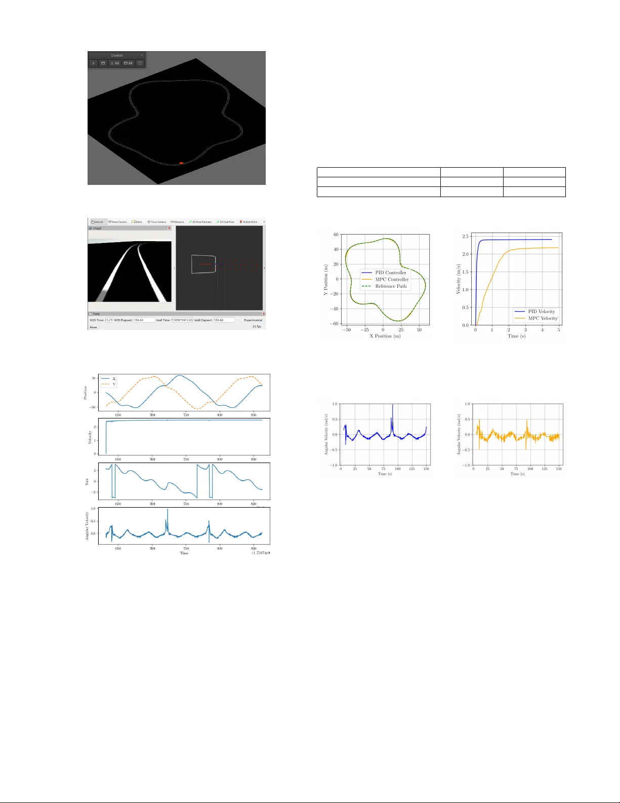
MonoSIM: An open source SIL frame work for Ackermann V ehicular Systems with Monocular V ision Shantanu Rahman* Department of Electrical and Electr onic Engineering Islamic University of T echnology Gazipur , Bangladesh shantanurahman@iut-dhaka.edu *Corresponding author Nayeb Hasin Department of Electrical and Electr onic Engineering Islamic University of T echnology Gazipur , Bangladesh nayebhasin@iut-dhaka.edu Mainul Islam Department of Electrical and Electr onic Engineering Islamic University of T echnology Gazipur , Bangladesh mainulislam@iut-dhaka.edu Md. Zubair Alom Rony Department of Electrical and Electr onic Engineering Islamic University of T echnology Gazipur , Bangladesh zubairalom@iut-dhaka.edu Golam Saro war Department of Electrical and Electr onic Engineering Islamic University of T echnology Gazipur , Bangladesh asim@iut-dhaka.edu ©2026 IEEE. Personal use of this material is permitted. Permission from IEEE must be obtained for all other uses, in any current or future media, including reprinting/republishing this material for advertising or promotional purposes, creating new collectiv e works, for resale or redistribution to servers or lists, or reuse of any copyrighted component of this work in other works. Abstract —This paper presents an open-source Software-in-the- Loop (SIL) simulation platform designed for autonomous Acker - man vehicle resear ch and education. The proposed framework f o- cuses on simplicity , while making it easy to work with small-scale experimental setups, such as the XTENTH-CAR platform. The system was designed using open source tools, creating an envir on- ment with a monocular camera vision system to capture stimuli from it with minimal computational overhead through a sliding window based lane detection method. The platform supports a flexible algorithm testing and validation envir onment, allowing resear chers to implement and compare various control strategies within an easy-to-use virtual en vironment. T o validate the work- ing of the platform, Model Predicti ve Contr ol (MPC) and Propor - tional–Integral–Derivati ve (PID) algorithms were implemented within the SIL framew ork. The results confirm that the plat- form pro vides a reliable en vironment for algorithm verification, making it an ideal tool f or future multi-agent system research, educational purposes, and low-cost A GV development. Our code is available at https://github .com/shantanu404/monosim.git . Index T erms —Softwar e-in-the-Loop (SIL), Monocular Vision, Lane Detection, Ackermann Steering, Model Predictive Control (MPC), PID Control, Robot Operating System (R OS2), V ision- Based Navigation, A utonomous Ground V ehicles (A GV) I . I N T RO D U C T I O N Autonomous vehicles are quickly becoming a key trans- portation technology . Companies like T esla are accelerating dev elopment and increasing market demand. In many de- veloped countries, users are beginning to depend on these systems [ 1 ]. Since human error remains a major cause of road accidents, autonomous dri ving of fers a promising pathway tow ard improved safety [ 2 ]. Motiv ated by these trends, we introduce MonoSIM, a lightweight and accessible simulation testbed designed to support research on autonomous vehicle navigation. MonoSIM is built on top of the Robot Operating Sys- tem (R OS) and the MVSIM simulator [ 3 ], which incor- porates the Box2D physics engine. Through this design, MonoSIM enables lane-tracking experiments using monocu- lar vision and widely used control algorithms. The frame- work provides telemetry e xtraction, real-time sensor emu- lation, and a flexible en vironment for dev eloping low-le vel vision pipelines—capabilities that are often restricted in tra- ditional control-focused simulators. MonoSIM places empha- sis on real-time sensor data processing, dynamic region-of- interest extraction for lane detection, sliding-window tech- niques, quadratic curve fitting, and improved transparency of the simulation en vironment. Practical constraints such as limited computational power and lo w-resolution camera input are also taken into consideration within the system’ s design. Sev eral prior works hav e proposed testbeds for autonomous systems. Jiang et al. integrated an MPC framework with a learning-based error estimator using offline data [ 4 ]. Bhadani et al. developed the “CA T V ehicle T estbed” using R OS and Gazebo to support hardware-in-the-loop experimentation [ 5 ]. Sarantinoudis et al. presented a R OS-based platform sup- porting V2V and V2I communication [ 6 ]. Elmoghazy et al. proposed an edge-enhanced V2X testbed using an F1T enth- scale vehicle [ 7 ]. Bouchemal et al. constructed a real-world DSRC-based V2X infrastructure [ 8 ]. Additional contributions include fault-simulation platforms [ 9 ], large-scale heteroge- neous testbeds [ 10 ], controlled-en vironment autonomous pro- totypes [ 11 ], reconfigurable multi-sensor platforms [ 12 ], radar- focused MA TLAB testbeds [ 13 ], integrated U A V–UGV envi- ronments [ 14 ], and digital-twin-supported hybrid testbeds [ 15 ]. Compared to these existing platforms, MonoSIM offers lower computational demands and improved scalability for testing and comparing autonomous vehicle control algorithms within a unified monocular-vision-dri ven simulation en viron- ment. I I . M E T H O D O L O G Y Sensors and locomotion are necessary to make interaction with the en vironment. In our testbed, we used a monocu- lar camera ( Logitech c310 HD ) to observe the environment around. For actuation, the car model we de veloped, follo ws the mathematical model of ackermann steering using an approxi- mation of the bicycle model. Ackermann steering helps to turn a car by adjusting the rotating angle of wheels according to their position where, The bicycle model simplifies the vehicle’ s dynamics by representing the vehicle with a single front wheel and a single rear wheel. A. CALIBRA TION For consistent processing, a frame from the target environ- ment was taken and enlarged to 640 × 480 pixels. OpenCV was used to conv ert the image from BGR to RGB format for viewing. Fig. 1: Original input frame Fig. 2: Birds Eye V iew A homography-based perspectiv e transformation was used to create a top-down vie w . After the source and destination points were manually specified, the Direct Linear Transforma- tion algorithm was used to calculate the transformation matrix. After that, the picture was distorted to a corrected viewpoint. The calibration was performed using a 5 × 4 chessboard. Using OpenCV’ s findChessboardCorners with adap- tiv e thresholding and normalizing for enhanced robustness, chessboard corners were identified after the corrected image was conv erted to grayscale. Corner positions were refined to subpixel accuracy using cornerSubPix , and the results were visualized for verifica- tion. The corner coordinates were reshaped to ev aluate geomet- ric consistency , and a verage spacing between adjacent corners was computed in both horizontal and vertical directions. Finally , the homography matrix was printed and confirmed. This matrix provides a geometric mapping between original and rectified views and is essential for applications such as camera calibration, navigation, and ground plane analysis. Fig. 3: Detected and refined chessboard corners overlaid on the grayscale image. B. LANE DETECTION The feature-based lane detection pipeline uses edges and local visual cues such as gradients and intensity variations, which remain stable across dif ferent road geometries but may vary with illumination. The camera output is first resized to 640 × 480 and undistorted using the intrinsic camera matrix obtained by camera calibration. Because fitting polynomials directly on the perspective image would require high-order models, a bird’ s-eye view transform is applied [ 16 ] to make the lanes parallel and fit them using a second or third-order polynomial (see Fig. 4 and Fig. 5 ). Fig. 4: Lane visible in camera Fig. 5: Bird’ s Eye view After warping, the image is con verted to HSV , and lane features are isolated primarily from the V alue channel. The lower half of this channel is processed using Gaussian blurring, thresholding, and morphological filters. A vertical histogram of pixel intensities is then used to estimate the initial left and right lane positions Fig. 6: Implementation of Sliding window technique Lane pixels are extracted using a sliding-window method, where windo ws move upward along the image to collect connected lane points. Separate polynomials are fitted to the left and right lane boundaries, providing a continuous representation of lane geometry . (Fig. 6 ). An overvie w of the entire pipeline is shown in Fig. 7 . Fig. 7: Overall lane detection pipeline C. VEHICLE D YNAMICS Before dev eloping our vehicle dynamics model, we are assuming only 3 DOF of motion for our autonomous vehicle i.e. lateral, longitudinal and yaw motion. W e are also making some assumption based on 3 DOF motions which are as follows [ 17 ]: • For the front and rear axles, the wheels are considered lumped together . • Assuming fixed velocity for our autonomous vehicle • Maneuvering only the front axel. • The weight distribution is considered uniform throughout the body and extra dynamics such as suspension, aero- dynamics, and slip factors are discarded Considering Ne wton’ s Second Law of motion for 3 DOF [ 18 ], vehicle dynamics model can be constructed as : m ( ¨ y + ˙ x ˙ ϕ ) = 2( F y f sin δ f + F cf cos δ f ) + 2 F cr (1) I z ¨ ϕ = 2 b ( F y f sin δ f + F cf cos δ f ) − 2 aF cr (2) In the above equation V ehicle mass is denoted using m, inertia along z axis is denoted using I z , ϕ and δ f are the yaw and steering angle respectively . Distance from the center of gravity to the front and rear axels are denoted using b and a respectiv ely . Pacejka tire model [ 19 ] is applied in this paper , Where the cornering angle and slip ratio of tire are quite small, the linearized and simplified formulas of longitudinal force and lateral force in the tire model are giv en by: F cf = C cf α f (3) F cr = C cr α r (4) where C c f and C c r are the front and the rear cornering tire stiffness coefficient, respectiv ely . Similarly , α f and α r are the front and rear tire slip angles, respectiv ely . Real time performance can be improv ed and optimized by con verting the nonlinear dynamic model into the state space model and linearized, where χ = ˙ x, ˙ y , ϕ, ˙ ϕ T is the state space vector and the control variable is u = δ f [ 20 ] to increase the versatility of the model and approximate linearized model is formed. Fig. 8: Dynamics of Ackermann model where A t = ∂ f ( χ, u ) ∂ χ χ = χ 0 ; u = u 0 (5) B t = ∂ f ( χ, u ) ∂ u χ = χ 0 ; u = u 0 (6) Y t = ϕ Y C t = 1 , 0 , 0 , 0 T (7) Due to the continuous nature of the above equation, these equations cannot be applied directly into the model predictiv e control algorithm, so discretization is performed. χ ( k + 1) = A k χ ( k ) + B k u ( k ) (8) Y ( k ) = C k χ ( k ) (9) D. ST ATE AND OUTPUT PREDICTION In the process of path tracking, we need to predict the future behavior of vehicle in the specified prediction horizon, and calculate the control input in the next moment by minimizing the error between predicti ve v ariables and the references under various constraints. Giv en that the input of the model is the control increment ∆ u ( k ) of the control signal u ( k ) , an incremental state space model is formulated as follows: ˜ χ ( k + 1) = ˜ A k ˜ χ ( k ) + ˜ B k ∆ u ( k ) (10) ˜ Y ( k ) = ˜ C k ˜ χ ( k ) (11) Where the symbols retain their traditional meaning. T o forecast the system’ s state at future intervals, assuming the current sampling time is k , where k > 0 , and the state variable vector ˜ χ ( k ) denotes the present system information. The forthcoming control sequence is represented by ∆ u ( k + j ) = 0 , where j = N c , N c + 1 , . . . , N p − 1 . N c and N p denote the control and prediction horizons, respectiv ely . ∆ U a ( k ) ≜ ∆ u ( k ) ∆ u ( k + 1) . . . ∆ u ( k + N c − 1) ( N c × 1) (12) ˜ χ ( k + 1 | k ) = ˜ A k ˜ χ ( k ) + ˜ B k ∆ u ( k ) ˜ χ ( k + 2 | k ) = ˜ A k +1 ˜ A k ˜ χ ( k ) + ˜ A k ˜ B k ∆ u ( k ) + ˜ B k +1 ∆ u ( k + 1) . . . ˜ χ ( k + N c | k ) = α ( k, N c − 1 , 0) ˜ χ ( k ) + α ( k , N c − 1 , 1) ˜ B k ∆ u ( k ) + · · · + ˜ B k + N c − 1 ∆ u ( k + N c − 1) . . . ˜ χ ( k + N p | k ) = α ( k, N p − 1 , 0) ˜ χ ( k ) + α ( k , N p − 1 , 1) ˜ B k ∆ u ( k ) + · · · + α ( k , N p − 1 , N c ) ˜ B k + N c − 1 ∆ u ( k + N c − 1) (13) The prediction horizon is equal to or, often times, greater than the control horizon. Consequently , the prediction input vector ∆ u a ( k ) can be delineated. State vector and output of ev ery sample instance in the prediction horizon can be formulated in Eq 13 . Using similar technique we can then calculate trajectory for any giv en set of input controls for the horizons. E. CONSTR UCTION OF COST FUNCTION The fundamental goal of the controller is to determine the sequence of control actions that will minimize the sum of the squared deviations of the expected output from the reference trajectory . This is the basic objective of the controller , the cost function can be defined as: J k = l ˜ Y ( a, ref ) ( k ) − ˜ Y a ( k ) m T Q l ˜ Y ( a, ref ) ( k ) − ˜ Y a ( k ) m + ∆ U T a ( k ) R ∆ U a ( k ) (14) The matrices that contain the weights of the inputs and outputs are denoted as Q and R . The matrix ˜ Y ( a, ref ) ( k ) is the reference matrix. For this experiment they have been tuned manually . I I I . E X P E R I M E N T A L S E T U P The validation of the proposed method is performed on an Ubuntu 24.04 L TS, equipped with a 12 generation Intel Core i7 mobile processor . T o make sure we test the algorithms on isolation, we aimed to make the en vironment as abstract as possible to av oid any bias. For that reason, we chose MVSIM as our simulation platform which boasts on its 2.5D capable simulation us- ing Box2D engine [ 3 ]. ROS2 messaging service was used to communicate between the simulation and the algorithm process. ROS2 was chosen because it provided modularity and scalability to the system. The simulation was run in the above- mentioned setup together with some other ros2 nodes that collected odometry data for comparison with other algorithms. The graph in Fig. 9 shows all the components that were run in a standard experiment. The en vironment was almost black and white with clearly defined lane lines to indicate the vehicle path. This was in turn detected from the environment using the described method in Section II-B . This process is analogous to the SO T A ML models segmenting the image into different lane lines. T ogether with some calibration data from the monocular camera, we were able to deduce the physical points in the actual world. This is again analogous to the case for ML models deducing the depth of pix els in the image. This allo wed us to focus only on fine-tuning the underlaying algorithm without being concerned with other external factors. Fig. 9: Software Architecture of Simulation The controller node is responsible for driving the car . It does so by sending the simulator program its desired throt- tle (accelaration) and steering angle in the form of a ros2 twist message. The controller derives these values from the input camera image and the car’ s speed using a simulated speedometer sensor located on the v ehicle. The controller node then processes this information with the desired algorithm to dictate the throttle/brake and steering angle of the vehicle. Figure 11 shows ROS2 rviz showing the monocular camera output along with the detected lane and the predicted path to follo w . In Figure 10 , we can see that MVSIM simulated world in isometric view . Figure 12 sho ws a sample runtime information of the vehicle while running the simulation. The plots consecutiv ely show its current position in world coordinates, the velocity and the heading angle along with it’ s angular velocity . Fig. 10: MVSIM Simulation platform Fig. 11: R V iz showing debugging information Fig. 12: Sample Runtime Information I V . R E S U LT S & O B S E R V A T I O N The experiment was conducted across multiple trials using randomly generated tracks of similar complexity , created by adding sinusoidal curvatures to a uniform circular path, as illustrated in Fig. 13 . The initial velocity profiles of the vehicle for PID and MPC controllers are depicted in Fig. 14 . Over - all, both controllers demonstrated comparable performance; howe ver , they each exhibit distinct operational characteristics. The PID controller maintained an almost constant velocity throughout each run, including sharp turns. The behavior produced apparent spikes in angular velocity , as shown in Fig. 15 . In contrast, MPC produced smoother and more regulated control actions. Its adherence to state and input constraints, howe ver , introduced oscillations in angular velocity (Fig. 16 ) and tracking error . Consequently , PID achiev es lower trajec- tory deviation, while MPC provides more robust, constraint- aware control at the expense of some accuracy , as summarized in T able I . T ABLE I: Mean Squared Deviation from all of the runs Metric PID MPC Lateral Mean Squared Deviation 0.0136 m 2 0.0390 m 2 Angular Mean Squared Deviation 0.000548 r ad 2 0.001014 r ad 2 Fig. 13: V ehicle T rajectories in ev ery run Fig. 14: Initial vehicle veloc- ities Fig. 15: Angular V elocity - PID Fig. 16: Angular velocity - MPC C O N C L U S I O N S This work presents a lo w-cost, open-sourced SIL framework for Ackermann-steered autonomous vehicles by incorporating monocular vision, real-time telemetry , and fle xible control experimentation. The platform allows for reliable testing of lane-tracking algorithms while maintaining low computational ov erhead. Experiments with PID and MPC controllers sho w that the testbed successfully reflects the differences in control behavior: PID has a smaller tracking error , whereas MPC offers much smoother, constraint-aware control. The results presented herein validate this framew ork as a practical means of dev eloping and comparing algorithms. The overall system is set up to be easily extensible for future studies in multi-agent scenarios, learning perception, and onward development into Hardware-in-the-Loop tests. R E F E R E N C E S [1] Monika Stoma, Agnieszka Dudziak, Jacek Caban, and Paweł Dro ´ zdziel. The future of autonomous vehicles in the opinion of automotiv e market users. Energies , 14(16):4777, 2021. [2] Alireza T alebpour and Hani S Mahmassani. Influence of connected and autonomous vehicles on traffic flow stability and throughput. T rans- portation resear ch part C: emerging technologies , 71:143–163, 2016. [3] Jos ´ e-Luis Blanco-Claraco, Borys T ymchenko, Francisco Jos ´ e Ma ˜ nas- Alvarez, Fernando Ca ˜ nadas-Ar ´ anega, ´ Angel L ´ opez-G ´ azquez, and Jos ´ e Carlos Moreno. Multiv ehicle simulator (mvsim): Lightweight dynamics simulator for multiagents and mobile robotics research. Soft- war eX , 23:101443, 2023. [4] Chaoyang Jiang, Hanqing Tian, Jibin Hu, Jiankun Zhai, Chao W ei, and Jun Ni. Learning based Predictiv e Error Estimation and Compensator Design for Autonomous V ehicle Path Tracking. In 2020 15th IEEE Confer ence on Industrial Electronics and Applications (ICIEA) , pages 1496–1500, November 2020. ISSN: 2158-2297. [5] Rahul Kumar Bhadani, Jonathan Sprinkle, and Matthew Bunting. The CA T V ehicle T estbed: A Simulator with Hardware in the Loop for Autonomous V ehicle Applications, April 2018. arXiv:1804.04347 [cs]. [6] Nikolaos Sarantinoudis, George Tsinarakis, Lefteris Doitsidis, Savvas Chatzichristofis, and George Arampatzis. A R OS-Based Autonomous V ehicle T estbed for the Internet of V ehicles. In 2023 19th International Confer ence on Distributed Computing in Smart Systems and the Internet of Things (DCOSS-IoT) , pages 726–733, June 2023. ISSN: 2325-2944. [7] Ammar Elmoghazy , Khalid Elgazzar , and Sanaa Alwidian. A Real- W orld T estbed for V2X in Autonomous V ehicles: From Simulation to Actual Road T esting. In 2024 IEEE 8th International Conference on F og and Edge Computing (ICFEC) , pages 89–94, May 2024. ISSN: 2694-3255. [8] Naila Bouchemal and Sondes Kallel. T estbed of V2X infrastructure for autonomous vehicles. Annals of T elecommunications , 76(9):731–743, October 2021. [9] Liang T ang, Eric Hettler , Bin Zhang, and Jonathan DeCastro. A T estbed for Real-T ime Autonomous V ehicle PHM and Contingenc y Management Applications. Annual Conference of the PHM Society , 3(1), September 2011. [10] Joaquin D. Labrado, Berat A. Erol, Jacqueline Ortiz, Patrick Benavidez, Mo Jamshidi, and Benjamin Champion. Proposed testbed for the modeling and control of a system of autonomous vehicles. In 2016 11th System of Systems Engineering Confer ence (SoSE) , pages 1–6, June 2016. [11] Samy El-T awab, Nathan Sprague, and Azeem Mufti. Autonomous V ehicles: Building a T est-bed Prototype at a Controlled Environment. In 2020 IEEE 6th W orld F orum on Internet of Things (WF-IoT) , pages 1–6, June 2020. [12] Zheng Gong, W uyang Xue, Ziang Liu, Yimo Zhao, Ruihang Miao, Rendong Y ing, and Peilin Liu. Design of a Reconfigurable Multi-Sensor T estbed for Autonomous V ehicles and Ground Robots. In 2019 IEEE International Symposium on Cir cuits and Systems (ISCAS) , pages 1–5, May 2019. ISSN: 2158-1525. [13] Jorge M. V argas, Suleiman Alsweiss, Michael Jernigan, Abu Bony Amin, Marius Brinkmann, Joshua Santos, and Rahul Razdan. De- velopment of Sensors T estbed for Autonomous V ehicles. In 2019 SoutheastCon , pages 1–4, April 2019. ISSN: 1558-058X. [14] Armin Mokhtarian, Jianye Xu, Patrick Scheffe, Maximilian Kloock, Simon Sch ¨ afer , Heeseung Bang, V iet-Anh Le, Sangeet Ulhas, Johannes Betz, Sean W ilson, Spring Berman, Liam Paull, Amanda Prorok, and Bassam Alrifaee. A Surve y on Small-Scale T estbeds for Connected and Automated V ehicles and Robot Swarms: A Guide for Creating a New T estbed [Survey]. IEEE Robotics & Automation Magazine , 32(3):146– 163, September 2025. [15] Anil G ¨ urses, Gautham Reddy , Saad Masrur, ¨ Ozg ¨ ur ¨ Ozdemir , ˙ Ismail G ¨ uvenc ¸ , Mihail L. Sichitiu, Alphan S ¸ ahin, Ahmed Alkhateeb, Magreth Mushi, and Rudra Dutta. Digital T wins and T estbeds for Supporting AI Research with Autonomous V ehicle Networks. IEEE Communications Magazine , 63(4):56–62, April 2025. [16] Guizhen Y u, Zhangyu W ang, Xinkai W u, Y along Ma, and Y unpeng W ang. Efficient lane detection using deep lane feature extraction method. SAE International Journal of P assenger Cars-Electr onic and Electrical Systems , 11(07-11-01-0006):57–66, 2017. [17] Y iqi Gao. Model pr edictive contr ol for autonomous and semiautonomous vehicles . University of California, Berkeley , 2014. [18] Hengyang W ang, Biao Liu, Xianyao Ping, and Quan An. Path tracking control for autonomous vehicles based on an improved mpc. IEEE access , 7:161064–161073, 2019. [19] Shuo Cheng, Liang Li, Hong-Qiang Guo, Zhen-Guo Chen, and Peng Song. Longitudinal collision av oidance and lateral stability adapti ve control system based on mpc of autonomous vehicles. IEEE T ransac- tions on Intelligent T ransportation Systems , 21(6):2376–2385, 2019. [20] Mohit Batra, John McPhee, and Nasser L Azad. Anti-jerk model predictiv e cruise control for connected electric vehicles with changing road conditions. In 2017 11th Asian Control Conference (ASCC) , pages 49–54. IEEE, 2017.
Original Paper
Loading high-quality paper...
Comments & Academic Discussion
Loading comments...
Leave a Comment