Synapse-Inspired Energy Networks: A Neuromorphic Approach to Microgrid Protection without Communication Links
Traditional protection systems for microgrids, which rely on high fault currents and continuous communication, struggle to keep up with the changing dynamics and cybersecurity concerns of decentralized networks. In this study, we introduce a novel bi…
Authors: Saurabh Prabhakar, Bijaya Ketan Panigrahi, Frede Blaabjerg
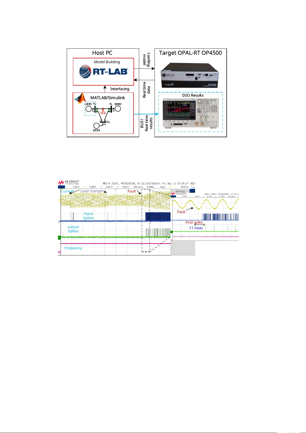
Synapse-Inspired Energy Net w orks: A Neuromorphic Approac h to Microgrid Protection without Comm unication Links Saurabh Prabhak ar 1* , Bija ya Ketan P anigrahi 1 , F rede Blaab jerg 2 , Subham Saho o 2 1* Departmen t of Electrical Engineering, I IT De lhi, Hauz Khas, 110016, Delhi, India. 2 Departmen t of Energy , Aalb org Universit y , 9220 Aalb org East, Denmark. *Corresp onding author(s). E-mail(s): e ez228471@iitd.ac.in ; Con tributing authors: bkpanigrahi@ee.iitd.ac.in ; fbl@energy .aau.dk ; sssa@energy .aau.dk ; Abstract T raditional protection systems for microgrids, whic h rely on high fault curren ts and contin uous comm unication, struggle to keep up with the c hanging dynamics and cybersecurity concerns of decen tralized net works. In this study , we in troduce a nov el biologically inspired protection system based on neuromorphic princi- ples, where eac h distributed energy resource (DER) functions as a simple neuron. These ”neurons” pro cess local changes in voltage, current signals, and con vert- ing them into spik e patterns that represen t the severit y of disturbances. Just as neurons communicate via synapses in biological systems, we exploit transmis- sion cables to co ordinate b etw een DERs, enabling them to share information and resp ond to faults collectively . F ault detection and circuit breaker activ a- tion are driv en by a First-T o-Spike (FTTS) mec hanism, similar to the concept of trav eling w av e protection, but without needing GPS sync hronization or com- m unication links. A key innov ation is the abilit y to use the timing of spikes to lo cally determine the nature of a fault, offering an in telligent, adaptiv e response to disturbances. Performance sho ws tripping latency of 10–58 ms, surpassing con ven tional relays and even trav eling-wa v e metho ds (60 ms), while maintain- ing detection accuracy ab ov e 98% and spatial selectivit y o ver 97%, enabling real-time, comm unication-free, scalable protection for plug-and-play microgrids. 1 Keyw ords: Neuromorphic protection, Spike-based logic, In verse-time dynamics, Communication-free relaying, Adaptive thresholding, Energy-a ware sensing, IDMT duality 1 In tro duction As mo dern p o wer systems ev olve tow ards decen tralization, microgrids hav e b ecome essen tial for in tegrating renew able energy and enhancing lo cal resilience [ 1 , 2 ]. These microgrids are t ypically p ow ered by in verter-based distributed energy resources (DERs), such as solar PV and energy storage, that offer flexible control but depart fundamen tally from traditional protection assumptions [ 3 – 5 ]. Unlike synchronous mac hines, inv erters limit fault curren t based on internal constrain ts, making it diffi- cult to distinguish faults from routine disturbances [ 6 ]. Moreov er, frequent changes in top ology due to DER switching, re-islanding, or v arying loads undermine the effec- tiv eness of time-grading and imp edance-based protection strategies. Efforts to adapt classical sc hemes such as directional, distance, and differen tial relays hav e in tro- duced enhancements like voltage sup ervision [ 7 ], sequence-dro op comp ensation [ 8 ], and adaptiv e thresholds. How ever, these tec hnologies still dep end hea vily on high fault curren ts or synchronized phasor data, whic h may be unreliable in inv erter-dominated en vironments [ 9 , 10 ]. T o o vercome these challenges, recent arc hitectures hav e em braced comm unication- assisted strategies. Cen tralized protection sc hemes using artificial neural netw orks [ 11 ], phasor measurement units (PMU)-enabled distributed consensus [ 12 ], and hybrid logic-based protection [ 13 ] improv e resp onse sp eed and fault lo calization. How ever, these solutions introduce new vulnerabilities, including latency , data loss, jitter, and cyb er threats, especially under adversarial conditions. As a partial remedy , co-transfer comm unication metho ds like P ow er T alk and T alk ative P ow er embed control signals in to v oltage w av eforms or con verter dynamics [ 14 ]. How ever, they face practical issues including limited bandwidth, sensitivit y to EMI, and po or transformer compatibilit y— constraining their scalability . Semantic comm unication framew orks that fo cus on ev ent-driv en signaling and predictiv e timing [ 15 ] offer additional resilience but remain complex to implemen t. A t the same time, trav elling wa ve (TW) protection has gained attention as a comm unication-free metho d that detects faults within a fraction of a cycle by sens- ing high-frequency wa vefron ts generated during a fault ev ent. TW schemes, which use GPS-synchronized sensors, work well in large or hybrid p ow er systems [ 16 ]. How- ev er, their effectiv eness decreases in lo w-voltage or meshed microgrids, where signal reflections, noise, and w eak wa v eforms from nearby faults can interfere with detection. These challenges highligh t the need for new protection strategies that are ultra-fast, lo cally op erated, and do not rely on comm unication—particularly for lo w-inertia and reconfigurable microgrids. Neuromorphic protection is an emerging approac h that applies principles from biological neural systems to p ow er net works, enabling lo cal, even t-driven intelligence b y lev eraging the physical wiring b et ween sources in a microgrid [ 17 , 18 ]. The Spike 2 T alk architecture was one of the first to introduce this concept to p ow er systems, mo deling eac h distributed energy resource (DER) as a leaky in tegrate-and-fire (LIF) neuron. These neurons autonomously monitor lo cal voltage and current signals and generate spike trains to enco de op erational disturbances. Unlik e conv en tional systems that rely on contin uous comm unication, these spikes are pro cessed async hronously and lo cally , with resp onses triggered only when signal thresholds are exceeded–allowing for decentralized and real-time fault detection [ 19 ]. Building on this foundation, Diao et al. [ 20 , 21 ] prop osed ev ent-driv en coordina- tion framew orks using spiking neural netw orks (SNNs), in whic h decisions are initiated b y meaningful even ts rather than contin uous data exchange. This represents a con- ceptual shift—from systems that communicate ab out p ow er to systems that r e ason with p ow er—where protection decisions are guided by spik e timing and the in ternal dynamics of the netw ork itself. Notably , the spik e-based mechanism in neuromorphic protection parallels the logic of trav eling wa v e (TW) protection sc hemes. TW metho ds detect and lo calize faults b y identifying the earliest arriv al of high-frequency wa vefron ts at spatially distributed sensors. Similarly , in the neuromorphic approach, the first DER to spike o ccurrence indicates the fault’s proximit y . Ho w ever, unlike TW systems, which require GPS syn- c hronization, high-sp eed sensors, and dedicated communication infrastructure, the neuromorphic metho d op erates without an y of these dep endencies. Instead, it pro- vides a scalable, and inherently comm unication-free solution for fast and resilient fault detection. T o address the limitations of conv entional protection systems, we in tro duce a neu- romorphic framew ork in this paper inspired by the dynamics of biological neurons. In this approac h, each distributed energy resource (DER) is modeled as a leaky in tegrate- and-fire (LIF) neuron that contin uously monitors lo cal voltage and current. These neurons emit spik es in resp onse to disturbances, with larger or closer faults causing earlier spik es. The DERs that spikes first extrapolates to be nearest to the fault and autonomously initiates selective circuit breaker tripping, thereb y enabling ultra-fast, fully decen tralized protection without the need for communication or sync hronization. This First-to-Spik e (FTTS) logic mirrors comp etitiv e neural b eha vior in biolog- ical systems, where the earliest spike enco des the most critical stimulus. Notably , the relationship betw een spike timing and disturbance magnitude follows an inv erse- time c haracteristic, conceptually similar to the in verse definite minimum time (IDMT) curv es used in traditional protection relays. This parallel establishes a mathemati- cal and functional dualit y betw een neuromorphic enco ding and classical rela y logic. Figure 1 summarizes the ov erall architecture, illustrating how LIF neuron mo dels, in verse-time spik e resp onses, and lo cal breaker actuation are com bined to realize a biologically-inspired protection system for microgrids. T o implemen t this arc hitecture in practice, each DER lo cally computes a scalar disturbance index defined as: D ( t ) = α | ∆ V ( t ) | + β | ∆ I ( t ) | + γ | ∆ P ( t ) | (1) where, the co efficien ts α , β , and γ w eigh v oltage, curren t, and p ow er deviations resp ec- tiv ely . This index mo dulates the in ter-spike in terv al via an inv erse-time relationship: 3 P r e - sy nap tic neur o n P o st - sy nap tic neur o n D e nd r ite Ne u r o - tr a n s m i tt e r s M o l e cul e s Sy na p t i c c l e f t Ne ur on Me m b r a ne Na + Na + E x t r a c e l l ul a r V V th V r O ( t ) I ( t ) t t t P r e - sy nap tic / i np ut sp ik e s P o st - sy nap tic / o utp u t sp ik e s R C V r V th I ( t) E lect r i c al m o d e li ng P o w e r e lect r o ni cs L f a 2 I 2 C 2 V 2 I 1 L f a 1 C 1 V 1 L 1f R 1f P 12 P 21 Fa ul t R 2f L 2f D E R 1 D E R 2 M ic ro g rid Ne u r os c ie n c e D E R L I F Neu ron L in e I m p e d a nc e Sy na p s e Fa ul t St im ul i I nt e ns ity D y na m ic T hr e s ho ld Ne ur o na l Pla s tic ity b c a d : C irc ui t B re a ke r Fig. 1 : Neuromorphic foundation of spik e-based protection for AC micro- grids : (a) A t wo-bus A C microgrid setup with inv erter-based DERs connected via a tie-line, protected b y circuit break ers at both ends. Eac h DER functions as an indepen- den t spiking unit, allowing fully decen tralized and communication-free protection. (b) Eac h DER is modeled as a Leaky Integrate-and-Fire (LIF) neuron, where inv erter-side capacitance and line resistance together replicate the b ehavior of a biological neuron’s mem brane using an equiv alent RC circuit. (c) The neuron accumulates input spik es o ver time, and once the membrane p oten tial crosses a voltage threshold, it emits an output spik e—mimicking ho w biological neurons fire. (d) Increasing disturbance sev er- it y shortens the spike interv al, resulting in faster spik e emission. This in verse-latency c haracteristic is mathematically equiv alent to the IEC 60255 Standard In verse time curv e, establishing a direct analytical bridge b et ween classical IDMT protection and the prop osed neuromorphic enco ding. T s ( t ) = 1 1+ kD ( t ) , where k > 0 gov erns the sensitivity to disturbances. As fault severit y increases, the disturbance index D ( t ) rises, resulting in shorter inter-spik e interv als and earlier spik e generation. This mec hanism effectiv ely em ulates the inv erse definite minim um time (IDMT) characteristics of conv entional protection relays, but through a biologically inspired, even t-driven pro cess. 4 1 2 E ve n t R e spo n se Fau l t 3 c 1 . 5 R21 T r ip p in g S ig nal 2 1 m se c 2 3 m se c 1 . 5 1 . 5 5 0 0 . 5 1 DE R 1 1 . 5 1 . 5 5 0 0 . 5 1 DER 2 0 0 . 5 1 DER 3 No S p ik e s T im e (se c) Tim e (s e c) T im e (se c) 1 . 5 5 L f a 1 D E R 1 L f a 1 D E R 1 C 1 L f a 1 D E R 1 C 1 L f a 2 D E R 2 L f a 2 D E R 2 C 2 L f a 2 D E R 2 C 2 L f a 3 D E R 3 C 3 b T im e (se c) 0 1 2 3 0 40 80 Dis tu r b a n ce I n de x I n p u t S p i k e s 0 1 2 3 0 5 10 15 V th V m 0 1 2 3 0 0 . 5 1 1 . 5 4 1 . 5 2 O u t p u t S p i k e s M e m b r a n e Dyn a m i c s T im e (se c) 0 0 . 5 1 0 1 2 3 0 0 . 5 1 0 1 2 3 1 2 Fau l t 3 L f a 1 D E R 1 L f a 1 D E R 1 C 1 L f a 1 D E R 1 C 1 L f a 2 D E R 2 L f a 2 D E R 2 C 2 L f a 2 D E R 2 C 2 L f a 3 D E R 3 C 3 Ada p ti ve t h r e sh o l d Da ta p r o ce ssi n g a F T T S C o d i n g T r i g g e r C B s R12 1) E ve n t - dri v e n spi ki n g 2) Sp i ke e n co d i n g & Ad ap ti ve L I F n e u ro n 3) FT T S de ci si o n & T ri pp i n g F i r st - sp i k i n g DER = cl o s e st to fa u l t 1 2 E ve n t R e spo n se Fau l t 3 c 1 . 5 R21 T r ip p in g S ig nal 2 1 m se c 2 3 m se c 1 . 5 1 . 5 5 0 0 . 5 1 DE R 1 1 . 5 1 . 5 5 0 0 . 5 1 DER 2 0 0 . 5 1 DER 3 No S p ik e s T im e (se c) Tim e (s e c) T im e (se c) 1 . 5 5 L f a 1 D E R 1 C 1 L f a 2 D E R 2 C 2 L f a 3 D E R 3 C 3 b T im e (se c) 0 1 2 3 0 40 80 Dis tu r b a n ce I n de x I n p u t S p i k e s 0 1 2 3 0 5 10 15 V th V m 0 1 2 3 0 0 . 5 1 1 . 5 4 1 . 5 2 O u t p u t S p i k e s M e m b r a n e Dyn a m i c s T im e (se c) 0 0 . 5 1 0 1 2 3 1 2 Fau l t 3 L f a 1 D E R 1 C 1 L f a 2 D E R 2 C 2 L f a 3 D E R 3 C 3 Ada p ti ve t h r e sh o l d Da ta p r o ce ssi n g a F T T S C o d i n g T r i g g e r C B s R12 1) E ve n t - dri v e n spi ki n g 2) Sp i ke e n co d i n g & Ad ap ti ve L I F n e u ro n 3) FT T S de ci si o n & T ri pp i n g F i r st - sp i k i n g DER = cl o s e st to fa u l t Fig. 2 : Sc hema of the prop osed spik e-based neuromorphic protection frame- w ork , which begins with (a) even t-driven sensing, where a load change around 0.5 s and a fault near 1.5 s create observ able c hanges in v oltage, current, and p o wer—resulting in a rise in the disturbance index D ( t ). These signals are then passed through (b) spike encoding, where local deviations are con verted in to input spik e trains based on their severit y . In mem brane in tegration and adaptiv e thresholding, the neu- ron in tegrates the input spik es, and the mem brane potential V m ( t ) rises un til it crosses the adaptive threshold V th ( t ), triggering an output spike. Finally , (c) the first-spiking neuron sends a trip command to its lo cal circuit breaker, isolating the faulted line. The en tire resp onse is fast, lo cal, and communication-free decision-making through async hronous spiking dynamics. 5 Conceptually , this timing-based resp onse mirrors the principles of trav eling wa ve (TW) protection, where the earliest arriv al of a w av efront indicates the fault’s lo ca- tion. In the prop osed framew ork, shorter inter-spik e interv als similarly correspond to higher lo cal disturbances, enabling spatially selective fault lo calization based on spik e latency—without requiring GPS synchronization or high-frequency sensing. T o enhance robustness during normal op eration, an adaptive thresholding mechanism is incorp orated. This threshold ev olves dynamically , informed by b oth the real-time disturbance index and the membrane p otential of the LIF neuron. Consequently , spik es are generated only in response to statistically significant anomalies, effectiv ely suppressing false p ositiv es arising from routine load v ariations or minor transien ts. The ensem ble of spike trains generated across DERs forms an asynchronous deci- sion lay er, in whic h the first neuron to spike autonomously activ ates its asso ciated circuit breaker (CB). This First-to-Spike (FTTS) mechanism 1 [ 22 ] enables sub-cycle fault protection based en tirely on lo cal sensing and spike timing, without the need for comm unication or synchronization. By eliminating centralized co ordination, the system enhances resilience to cyber-physical threats, comm unication delays, and net- w ork failures.This marks a shift from conv entional magnitude- or phasor-based logic to a fundamen tally new protection paradigm where decisions arise from spike-timing computation. Figure 2 illustrates the complete neuromorphic protection workflo w—from lo cal disturbance sensing to spike generation and CB actuation—highligh ting the architec- ture’s decentralized, biologically inspired logic. Supplementary Fig. 1 further con trasts this approac h with conv entional hierarc hical microgrid protection sc hemes, which t yp- ically rely on intelligen t electronic devices (IEDs), cen tral con trollers, and contin uous comm unication. In con trast, the proposed neuromorphic design ac hieves fast, robust, and fully lo calized decision-making.Notably , the membrane dynamics of the LIF neu- ron naturally pro duce an inv erse-time relationship b et ween disturbance severit y and spik e latency , establishing an emergent analogue to classical IDMT behavior without requiring preset curv es. T o ev aluate the prop osed framework, we p erformed extensive sim ulations across div erse fault and imp edance conditions. The neuromorphic system ac hieved sub-cycle detection and isolation within 10–58 ms: ABCG faults were cleared in 10 ms, ABG in 28 ms, and AG in 58 ms, compared with the 200–450 ms resp onse times of con- v entional microgrid protection. Spik e latencies sho wed a strong correlation with fault sev erity , reflecting in verse-time c haracteristics but realized through a lo cal, even t- driv en arc hitecture. Unlik e tra veling-w av e sc hemes that require GPS sync hronization and high-sp eed sensors for 60 ms operation, the neuromorphic approach ac hieves faster and fully selective protection using only lo cal spike timing, making it ideally suited for scalable, plug-and-pla y microgrids [ 23 ]. In addition to sp eed and accuracy , the framework offers several operational adv an- tages. The adaptive thresholding mechanism reliably suppresses false p ositiv es during normal load v ariations, while the First-to-Spike logic ensures that faults are lo cal- ized b y the DER nearest to the disturbance. This enables effective protection even 1 It should be noted that First-to-Spike co ding mechanism can normally b e abbreviated to FTS and FTTS. W e use FTTS consistently throughout this work. 6 in meshed netw orks with redundant paths. Ov erall, the prop osed approach bridges classical protection theory with neuromorphic computing. By com bining spik e-timing computation, emergen t inv erse-time b ehavior, and real-time v alidation on the OP4500 hardw are-in-the-lo op platform, it introduces a biologically inspired paradigm for decen tralized pow er system protection—one that senses lo cally , reacts instan tly , and adapts naturally to the ev olving dynamics of distributed energy net w orks. 2 Results W e assess the prop osed spik e-based neuromorphic protection framew ork in terms of sp eed, accuracy , and scalability across microgrids of v arying sizes and disturbance conditions. In this approach, eac h distributed energy resource (DER) is mo deled as a leaky integrate-and-fire (LIF) neuron that contin uously monitors lo cal v oltage, cur- ren t, and p ow er. Disturbances are enco ded into spik e timings, with more severe ev ents triggering faster spiking activity . Protection decisions follow a First-to-Spike (FTTS) rule: the DER that spikes first initiates lo cal circuit breaker actuation. W e ev aluate the system under a range of conditions, including single and multiple fault even ts, as well as b enign load v ariations, to demonstrate its robustness and adaptability in realistic, dynamic microgrid environmen ts. 2.1 Spike-Based F ault Resp onse Across Different Net work Conditions Case 1: F ault Detection Without Break er Action T o isolate and examine detection b ehavior, w e first study a three-bus ring microgrid (Supplemen tary Fig. 2a) with all circuit breakers disabled. As sho wn in Supplemen- tary Fig. 3, a normal load increase o ccurring at 0.5 s results in a mo derate rise in the disturbance index. The adaptive threshold responds gradually to this c hange, adjusting in line with the disturbance and effectiv ely prev enting the generation of unnecessary spik es. This b ehavior demonstrates the system’s ability to maintain selec- tivit y and av oid false p ositives during routine op erational v ariations. Later in the sim ulation, when a single-line-to-ground (SLG) fault o ccurs, the disturbance index D ( t ) increases sharply . The spik e interv al shortens, and the membrane potential V m ( t ) rapidly approaches the adaptiv e threshold, causing affected DERs to fire with sub-60 ms latency of fault onset. This confirms that the framew ork detects faults quic kly and with precise timing. Since the breakers are disabled, the fault is not isolated and propagates through the netw ork, leading to distorted line curren ts and frequency deviations. This exp eri- men t highligh ts the neuromorphic system’s ability to provide fast lo cal fault detection through biologically inspired spike-based enco ding without GPS synchronization or high-sp eed sensing. 7 Case 2: F ast F ault Isolation with FTTS-Enabled Break er Op eration in a Ring Microgrid W e then ev aluate the three-bus ring microgrid with the First-T o-Spike (FTTS) pro- tection logic enabled. Supplementary Fig. 4 demonstrates that when a fault o ccurs, the distributed energy resource (DER) closest to the fault exp eriences the highest disturbance index and is the first to generate spik e. This early spike autonomously triggers the circuit breakers at both ends of the faulted line. The protection response is completed within approximately t wo cycles—well b efore conv entional curren t tran- sien ts reac h their p eak—indicating that the decision is go verned by spike timing rather than current magnitude. Once the faulty segment is isolated, the rest of the microgrid stabilizes rapidly . These results confirm that fast, directional, and lo calized protec- tion can b e achiev ed entirely through decen tralized, spik e-based logic via the wired transmission lines. Case 3: Multi-F ault Adaptation and Scalabilit y in a Meshed Microgrid T o ev aluate adaptabilit y in more complex topologies, w e simulate a four-bus meshed microgrid (Supplementary Fig. 2b) sub jected to t wo consecutive disturbances: first, a line-to-line (LL) fault, follo wed by a more severe three-phase-to-ground (LLLG) fault. As sho wn in Supplementary Fig. 5, each DER resp onds indep enden tly based on lo cal measurements. The initial LL fault generates moderate spik e activity , while the subsequen t LLLG fault induces faster and denser spiking due to its higher sever- it y . The adaptive threshold adjusts dynamically , lo wering in resp onse to the stronger disturbance and enabling even earlier firing. In both cases, the corresp onding circuit breakers trip within a fraction of a cycle, isolating only the affected lines. The rest of the microgrid contin ues to operate with- out disruption. This exp eriment confirms that the FTTS-based protection framework scales effectiv ely to meshed netw orks, adapts to v arying fault t yp es and magnitudes, and deliv ers precise, selectiv e fault isolation—without requiring global co ordination or communication. 2.2 Stronger F aults Alw ays Cause F aster T ripping in Spik e-Based Protection DERs on lo w-imp edance lines detect and trip faster than those on higher-imp edance paths. F or instance, as shown in Fig. 3a, a DER connected through z = 2 Ω trips m uch earlier than one through z = 6 Ω, confirming that detection sp eed is go verned b y electrical distance, with nearb y faults isolated so oner than distan t ones.The membrane time constan t also plays a role: a smaller constan t allows the mem brane p otential to rise faster, leading to earlier spiking. In Fig. 3b, a neuron with τ = 86 . 4 µ s trips noticeably faster than one with τ = 161 µ s for the same fault, showing that relay-lik e time grading can b e tuned directly through neuron dynamics. F ault severit y further enhances the selectivity of the protection resp onse. The gain parameter k amplifies the impact of disturbances on spike generation, effectiv ely mo dulating the system’s sensitivit y . As sho wn in Fig. 3c, three-phase faults induce 8 a b c d Fig. 3 : Influence of electrical and neuromorphic parameters on spik e-driv en fault resp onse. (a) DERs connected through lo wer impedance lines (Z=2 Ω) detect faults faster than those on higher imp edance lines (Z=6 Ω), as stronger disturbances lead to earlier spik es. The observ ed in v erse-time b eha vior matc hes w ell with classical rela y logic. (b) A neuron with a smaller membrane time constan t ( τ = 86 µs ) spikes earlier than one with larger τ = 161 µs , highligh ting ho w spik e timing can be tuned biologically to reflect fault location. (c) T ripping time v aries with fault sev erity— quic kest for three-phase faults (LLL), slo wer for line-to-line (LL), and slo west for single-line-to-ground (LG)—mimicking classical selectivity . (d) The 3D surface shows ho w tripping time decreases with increased disturbance and low er fault resistance, replicating the behavior of in verse-definite minimum time (IDMT) curv es using a fully lo cal, neuromorphic logic. the fastest spiking responses, follo wed by line-to-line and single-line-to-ground faults. This behavior demonstrates that the spike-based framew ork naturally prioritizes more sev ere disturbances, closely mirroring the logic of in verse-time rela ys. The combined influence of line imp edance, membrane time constant, and fault sev erity is summarized in Fig. 3d. A three-dimensional surface maps tripping time as a function of disturbance magnitude and fault resistance. The consistently do wnw ard slop e confirms that more sev ere and low er-resistance faults lead to faster isolation. These results reinforce that the neuromorphic protection framework replicates the k ey principles of classical in verse-time protection—achieving fast, graded, and fault- selectiv e responses. 9 F a u l t s L o a d C h a n g e 0 20 40 60 80 100 A c c u r a c y ( % ) T r i p p i n g A c c u r a c y & Se l e c t i v i ty 99 . 5 % 81 . 3 % 100 % τ 1 τ 2 L o a d a b 0 0 . 2 0 . 4 I nc or rec t T rip ( 0 ) C orrec t T rip ( 1 ) A c c u r a c y A c r o s s F a u l t T y p e s & R e s i s ta n c e s F a u l t T y p e F a u l t R e s i s t a n c e [ Ω ] Fig. 4 : Accuracy and selectivit y trends in spik e-based neuromorphic pro- tection: (a) Group ed bar plot illustrating the tripping accuracy of the spike-based neuromorphic protection scheme across different op erating scenarios, including low and high membrane time constants and load disturbance cases. The framework main- tains high accuracy ( > 99%) under low τ , around 81 . 3% under high τ , and 100% under load disturbances, highligh ting robustness and selectivity .(b) Bo x plot showing tripping accuracy across v arying fault resistances and fault t yp es. While the system p erforms reliably up to 0 . 5 Ω, o ccasional misclassifications occur in LG faults due to w eaker disturbance signatures. The results affirm the role of spike timing in capturing fault severit y and supp orting accurate, selective protection decisions. 2.3 Accuracy and Selectivity of Spik e-Based Protection W e tested the spike-based protection framework under a wide range of scenarios, including v ariations in fault resistance and sudden load changes. As shown in Fig. 4a, the framew ork provides fast and reliable fault detection while av oiding false trips during normal fluctuations. The membrane time constant τ strongly influences p er- formance: when τ is small ( τ = 86 µ s), the neuron in tegrates faster, fires earlier, and ac hieves o ver 99% detection accuracy . In con trast, a larger v alue of τ (e.g., τ = 161 µ s) slo ws the mem brane response, lo wering accuracy to approximately 81%. Even under load v ariations, the adaptive threshold mec hanism preven ts spurious spiking, result- ing in 100% correctness. Across all tested cases, the system maintains an a verage fault detection accuracy ab o ve 98%. F ault resistance also pla ys a critical role. As resistance increases, the magnitude of the disturbance signal decreases, making some fault ev ents more difficult to detect. As sho wn in Fig. 4b, the framework contin ues to identify most faults correctly . Some w eak single-line-to-ground faults at higher resistance v alues may escap e detection; ho wev er, the system still maintains selectivity by tripping only the affected no de, thereb y a voiding unnecessary isolation of health y parts of the netw ork. T ogether, these results demonstrate that spik e timing naturally adapts to fault strength: stronger disturbances induce earlier spik es, while normal load changes are effectively ignored. This dynamic balance allows the framework to deliver fast, selectiv e, and communication-free protection suitable for microgrid ecosystem. 10 2.4 E nergy Efficiency , Selectivit y , and Scalability in Spik e-Based Protection The prop osed neuromorphic framework sho ws t wo essential properties: it remains almost silen t during normal op erating conditions and b ecomes highly selective during faults, enabling fast and lo calized isolation. During load changes in microgrid, the system conserves energy by suppressing unnecessary spik es. As seen in Fig. 5a–b, the disturbance index and spike activit y rise only slightly , leading to just 5 spik es for a 20% increase in load and 11 spikes for a 40% increase. This quiet b eha vior demonstrates minimal energy use, as the adaptiv e threshold adjusts smo othly to blo ck false alarms. When faults occur, the resp onse b ecomes b oth urgen t and prop ortional to sev erity . In Fig. 5b, the mem brane potential V m exceeds the adaptiv e threshold V th only during critical disturbances, producing fast and dense spike trains. F or AG, ABG, and ABCG faults, the n umber of spikes rises sharply to 477, 688, and 831 in Fig. 5c, with the first spik es (corresp onding to the fault) appearing at 58 ms, 28 ms, and 10 ms, resp ectively . This pattern mirrors the inv erse-time principle of con ven tional rela ys, where stronger faults are alw ays cleared faster. Under the First-T o-Spike (FTTS) rule, only the distributed energy resource (DER) closest to the fault initiates spiking, while all others remain inactive. As sho wn in Fig. 5d, this ensures spatial selectivity: only the affected section is isolated, while the rest of the microgrid con tinues to op erate undisturb ed. T o further aid intuition, Supplemen tary Fig. 11 provides a clear system-level view, sho wing ho w spik e-based protection adapts seamlessly to b oth fault severit y and fault lo cation across all DERs. Our framework is designed to b e scalable, as demonstrated b y the test system results across four different configurations (Supplementary Figs. 2, 8). The effective- ness of this approac h in v arying system sizes and fault scenarios is further v alidated b y the results in Supplemen tary Figs. 4, 5, 9, and 10, where it is sho wn that the spike-based protection mechanism adapts seamlessly to b oth fault severit y and fault lo cation. This scalability ensures that our solution remains robust and efficien t regardless of system complexity or fault conditions. This b ehavior arises naturally from the underlying LIF neuron dynamics. Small, gradual disturbances during normal op eration cause slo w membrane p otential c hanges that rarely exceed the adaptive threshold, pro ducing minimal spikes. In con trast, sudden, severe faults rapidly increase the disturbance index, causing the membrane p oten tial to cross the dynamically low ered threshold and trigger immediate spikes. The spike in terv al compresses as the disturbance magnitude gro ws, offering a direct, real-time indication of fault severit y . Imp ortan tly , this mec hanism remains effectiv e under current-limited op eration of grid-forming (droop-controlled) DERs, where out- put curren ts saturate rapidly during faults, b ecause the disturbance index is jointly driv en by v oltage, curren t, and active-pow er deviations rather than curren t alone. The influence of DER-side ov ercurrent limiting on spike generation, mem brane dynam- ics, and FTTS decision-making is explicitly analyzed and v alidated in Supplemen tary Note 13. This mec hanism allows the system to ac hieve both energy-efficien t monitoring and fault-proportional responses without explicit comm unication or centralized co or- dination.T ogether, these prop erties highligh t how energy efficiency , fast resp onse, and 11 0 2 4 6 7 0 50 1 0 0 1 5 0 D i stu rban ce I n de x P ro fi l e I I II II III III IV IV V V 0 2 4 6 7 0 10 20 Me m bran e D y n ami cs I I II II III III IV IV V V S p i ke En co d i n g 0 1 2 3 4 5 6 7 T i m e [s ] 0 1 2 O u tpu t Sp i k e s 0 1 2 3 4 5 6 7 T i m e [ s ] 0 1 2 3 3.0 35 3.0 7 3 3.0 35 3.0 7 5 8 mse c 5 5.0 15 5.0 3 1 0 m se c 5 5.0 15 5.0 3 1 0 m se c 3 3 . 0 3 5 3 . 0 7 3 3 . 0 3 5 3 . 0 7 Faul t AG Faul t AB G Fa ult AB C G 4 0 % lo a d chan g e 2 0 % lo ad chan g e Fi r s t S p ik e 1 3 5 5 3 1 S p i k e co u n t: 477 688 831 V m V th V m V th a b c d Fig. 5 : Energy-efficien t and fault-sensitive spike resp onse. The neuromorphic pro- tection system shows selective activity based on disturbance sev erity . In (a), the disturbance index D i ( t ) rises gradually during load c hanges but sho ws a sharp increase during fault even ts. This is mirrored in (c), where the input spike activity remains sparse under load shifts but b ecomes dense and urgent under fault conditions. In (b), the mem brane p otential V m ( t ) increases o ver time and surpasses the adaptiv e threshold V th ( t ) only during critical disturbances, triggering output spik es. Subplot (d) high- ligh ts the timing of these output spikes, showing that more sev ere faults trigger faster resp onses—58 ms for an AG fault and just 10 ms for an ABCG fault. Finally , (b) sho ws that the total num b er of spikes scales with fault sev erity: 477 spik es for AG, 688 for ABG, and 831 for ABCG, demonstrating how the system maintains energy-efficient b eha vior during normal ev ents while intensifying its response during critical faults. spatial selectivity emerge in trinsically from the spike-based, neuromorphic protection paradigm, providing a foundation for robust, autonomous microgrid protection. 3 Discussion As microgrids evolv e into decentralized systems dominated by in verter-based sources, con ven tional protection strategies—ro oted in cen tralized co ordination and high fault curren ts—face increasing limitations. This study introduces a biologically inspired neuromorphic protection framework, where each Distributed Energy Resource (DER) functions as a Leaky Integrate-and-Fire (LIF) neuron, lo cally enco ding disturbances in voltage, current, and p ow er into asynchronous spik e trains. Protection decisions follo w a First-T o-Spike (FTTS) logic, analogous to tra v eling-wa ve methods that rely on the earliest signal arriv als for fault lo calization, but achiev ed here without requiring comm unication, GPS synchronization, or cen tralized coordination. 12 Sim ulation results show that spike timing dynamically mirrors the in verse-definite minim um time (IDMT) principle: stronger faults induce faster spik es and earlier trips, ac hieved through mem brane in tegration rather than preset rela y curv es. An adaptive thresholding mechanism further ensures reliability , suppressing b enign ev ents while p ermitting rapid action during genuine faults. Critically , only the DER electrically closest to the fault spik es first, enabling lo cal isolation without disrupting the wider net work. Bey ond accuracy and sp eed, the framew ork is also energy- and computation- efficien t. As sho wn in Section 2.4, the system remains dorman t during steady-state conditions and activ ates only in resp onse to s ignifican t disturbances. Spike count and computational effort scale with fault sev erity—reflecting the brain’s efficiency in resp onding only to m eaningful stimuli. More than just emulating con ven tional protection, this architecture extends and redefines it. Its spike-timing b ehavior is mathematically equiv alent to IDMT relays, yet the decen tralized, even t-driven nature mak es it scalable and plug-and-pla y . New DERs can b e added seamlessly , without system reconfiguration, making it ideal for dynamic, p eer-to-p eer microgrids. Lo oking ahead, this framew ork la ys the foundation for adaptiv e and learning-based protection. Integrating mechanisms lik e Spike-Timing Dep endent Plasticity (STDP) [ 22 ] could enable real-time threshold adaptation and con text-aw are resp onses. Beyond fault detection, the prop osed biologically inspired protection framew ork opens a broad landscap e for future research. Because disturbances are enco ded as sparse, even t- driv en spike trains rather than dense, con tinuous wa veforms, the metho d inherently filters out quiescen t p erio ds and concen trates computation only around informative transien ts, whic h reduces data v olume and pro cessing burden. This same spik e-based represen tation can b e reused for complementary protection functions suc h as islanding detection, even t classification, and fault-type lo calization by exploiting the spatio- temp oral firing patterns that emerge across m ultiple neuron-like DER agents.The form ulation also naturally supports adaptive learning mec hanisms—such as spike- timing-dep enden t plasticit y or lo cal rule-based threshold adaptation—which could enable automatic tuning under ageing, topology reconfiguration, or ev olving op erating conditions. F urthermore, the sparse and ev en t-driven nature of spike processing makes the approach w ell suited for implemen tation on emerging neuromorphic hardware platforms, offering the p otential for sub-millisecond protection decisions at extremely lo w computational cost. T ogether, these directions strengthen the broader vision of neuromorphic protection as a foundation for intelligen t, autonomous, and resilient next-generation microgrids. Although the prop osed neuromorphic protection framework is fully decentralized and light weigh t, sev eral practical considerations m ust be ackno wledged for real-w orld deplo yment. First, scalability across larger microgrids is inherently supp orted b ecause eac h DER neuron operates lo cally without comm unication; ho wev er, extremely large net works may require additional filtering to av oid spike collisions when many no des exp erience sim ultaneous but mild disturbances. Moreov er, while the core studies emplo y iden tical DER control structures for clarity , the framework is not restricted to homogeneous units; its applicability to microgrids with heterogeneous DER ratings 13 and con trol dynamics has b een explicitly examined, with detailed modeling, parame- ter sets, p erformance results, and discussion provided in Supplemen tary T ables 5–6, Supplemen tary Figs. 16–17, and Supplemen tary Note 12. Second, the method remains robust under weak-w av eform or low-v oltage faults—conditions where TW relays typi- cally struggle—b ecause spike generation dep ends on aggregated voltage, current, and p o wer deviations rather than high-frequency comp onents. Even when the wa veform is distorted or the voltage sag is shallow, the disturbance index still grows suffi- cien tly to compress spik e interv als and trigger a reliable FTTS response. Third, the framew ork assumes a v ailability of accurate lo cal sensing at eac h DER and a digital con troller capable of executing simple LIF updates at microsecond resolution, b oth of whic h are standard in present-da y inv erter hardware.Nonetheless, the method has limitations. Extremely high-resistance faults may pro duce disturbances just ab ov e the adaptiv e threshold, leading to slow er spik es compared to lo w-imp edance faults. Simi- larly , if extensive DER clustering results in nearly iden tical disturbance levels across no des, additional tie-line imp edance information ma y b e required to ensure unique FTTS resolution. These considerations do not undermine the metho d’s applicabil- it y but highligh t realistic boundaries and a ven ues for refinemen t. Ov erall, while fully compatible with a wide range of top ologies and operating conditions, the neuromor- phic approach—lik e all protection schemes—benefits from careful parameter tuning to ensure robust op eration under extreme or highly am biguous scenarios. 4 Metho ds 4.1 Sy stem Setup and T est Scenarios W e developed a low-v oltage islanded A C microgrid mo del in MA TLAB/Sim ulink (R2023a) to ev aluate the proposed neuromorphic protection strategy . The grid oper- ated at 415 V, 50 Hz, and included inv erter-based DERs, each rated at 10 kW. Two represen tative configurations were tested: a radial netw ork, where p o wer flows along a single path, and a meshed netw ork, characterized by multiple parallel paths that increase complexity in fault detection and isolation. Distribution lines w ere parameterized with resistance and reactance v alues, captur- ing characteristics of both underground and ov erhead cables. Detailed line parameters are provided in Supplementary T ables 1 and 2 . Each DER was equipped with lo cal curren t and voltage sensors, enabling protection decisions to b e made solely from local measuremen ts without communication or cen tralized co ordination. Tw o disturbance t yp es were applied. First, load v ariations of 20% and 40% simulated normal demand fluctuations. Second, faults were injected at v arious lo cations, including single-line-to- ground (A G), line-to-line (AB), and three-phase (ABC) faults. F ault resistance ranged from 0.001 Ω to 3 Ω, encompassing solid short circuits and high-impedance faults such as insulation breakdo wn or arcing. Ov er 300 simulation runs w ere conducted across both net work top ologies, encom- passing symmetrical and asymmetrical faults, a broad imp edance sp ectrum, and m ultiple DER placements. These scenarios enabled ev aluation of four critical metrics: detection sp eed, selectivit y , resilience to false trips, and p erformance under different 14 net work configurations. Crucially , the neuromorphic protection relied exclusively on lo cal sensing and spike-based neuron dynamics. 4.2 N euromorphic Mo deling of DERs as Leaky In tegrate-and-Fire (LIF) Neurons Eac h in verter-based DER was mo deled as a leaky in tegrate-and-fire (LIF) neuron, con- v erting lo cal disturbances into spik e signals. This biologically inspired design emp o wers eac h DER to indep endently make protection decisions without external co ordination. T o detect disturbances in the microgrid, each DER contin uously compares its mea- sured electrical quantities with their steady-state (pre-fault) v alues, denoted as V 0 , I 0 , and P 0 . The deviations are calculated as: ∆ V ( t ) = | V ( t ) − V 0 | , ∆ I ( t ) = | I ( t ) − I 0 | , ∆ P ( t ) = | P ( t ) − P 0 | (2) The disturbance index at an y DER is defined as (1): D ( t ) = α | ∆ V ( t ) | + β | ∆ I ( t ) | + γ | ∆ P ( t ) | where ∆ V ( t ), ∆ I ( t ), and ∆ P ( t ) represent the instan taneous deviations of voltage, curren t, and activ e p o wer from their steady-state v alues. Here, the voltage and current quan tities correspond to aggregated local three-phase RMS measures, while the activ e- p o wer term represents the instantaneous three-phase total active p o wer computed from the sum of p er-phase contributions. This unified representation is adopted for b oth symmetrical and asymmetrical fault conditions. Under un balanced faults, phase-level asymmetries, negative-sequence components, and second-order p ow er oscillations nat- urally manifest as increases in these aggregated quantities, thereb y pro ducing nonzero deviations in all three c hannels. As a result, the disturbance index inherently captures the presence and sev erity of asymmetrical faults without requiring explicit per-phase pro cessing or sequence decomp osition, preserving the simplicit y and lo cality of the prop osed form ulation. The weigh ting co efficients are α = 1 . 0, β = 0 . 5, and γ = 0 . 005, balancing contributions from all three signals.The chosen co efficients ( α = 1 . 0, β = 0 . 5, γ = 0 . 005) follow a scaling rationale based on the relative magnitudes of the under- lying signals. In in verter-dominated microgrids, ∆ V and ∆ I typically remain within 0–0 . 3 pu, whereas the active-pow er deviation ∆ P can be numerically one to t wo orders larger. T o preven t ∆ P from dominating the disturbance index, γ is selected several orders smaller, while α and β are c hosen to ensure a balanced contribution of the v oltage and current comp onents. In Supplementary Fig. 7, a detailed sensitivit y analysis was conducted to ev alu- ate robustness with respect to the disturbance-index weigh ts. A parameter sweep of α ∈ [0 . 5 , 2 . 0], β ∈ [0 . 25 , 1 . 5], and γ ∈ [0 . 001 , 0 . 02] was p erformed ov er 400 fault scenarios. Across these ranges, the detection accuracy remained ≥ 93 . 5%, and the median tripping latency v aried by less than 8 ms, indicating a broad plateau of stable p erformance around the nominal set ( α, β , γ ). The disturbance index drives the neuron’s membrane p oten tial V m ( t ) according to the differential equation: 15 C m dV m ( t ) dt = − V m ( t ) R m + D i ( t ) (3) where C m = 250 µ F and R m = 0 . 644 Ω, yielding a resp onse time constant τ = C m R m = 162 . 5 µ s. Small disturbances deca y naturally , while significan t ones cause rapid p otential rises. A spike is generated when V m ( t ) exceeds an adaptiv e threshold: V th ( t ) = V 0 exp [ − η ( | ∆ V | + | ∆ I | + | ∆ P | )] + λV m ( t ) (4) with V 0 = 17 . 9 V, η = 0 . 008, and λ = 0 . 6. This adaptiv e threshold ensures sensitiv- it y to genuine faults while filtering noise. Complete LIF neuron parameters, including v ariations to test robustness, are listed in Supplementary T able 3 . After spiking, the in ter-spike interv al T s ( t ) dep ends on disturbance sev erity: T s ( t ) = 1 1 + k D ( t ) (5) where, the gain k mo dulates spiking sp eed: higher k leads to faster spikes and quic ker breaker resp onse, whereas low er k results in more conserv ative op eration. Th us, each DER functions as an even t-driv en, self-contained neuron, linking lo cal disturbances directly to breaker trips. 4.3 First-to-Spike (FTTS) T ripping Mechanism Protection decisions utilize a First-T o-Spike (FTTS) rule among all DER neurons: the one generating the earliest spike is assumed closest to the fault and immediately trips its breaker. This guarantees rapid, decen tralized, and selective fault isolation. Unlik e phasor-based metho ds relying on communication and global thresholds, FTTS is inherently even t-driven. Only one break er operates per fault ev ent, namely the one asso ciated with the first spiking DER. Near-simultaneous spikes (within 3.125 µs ) are resolv ed via ” a winner-takes-al l ” mec hanism that suppresses subsequen t responses. Across more than 300 fault scenarios—including meshed top ologies and high- imp edance conditions—the FTTS rule achiev ed ov erall exceeding 98% lo cation accuracy and an av erage detection time b elow 25 ms, demonstrating robustness against both strong and w eak fault curren ts. Consequently , the neuromorphic strat- egy ac hieved fast, selective, and communication-free protection, a critical adv antage for inv erter-dominated microgrids where traditional schemes often fail. 4.4 Simulation Setup and Data Logging All simulations were performed in MA TLAB /Simulink (R2023a) using a fixed-step solv er with an in tegration step of 3 . 125 µ s, consisten t with the LIF neuron dynamics. A t eac h step, k ey v ariables were logged, including mem brane p otential V m ( t ), spike output S ( t ), disturbance index D ( t ), adaptive threshold V th ( t ), breaker status, and the three-phase voltage, current, and activ e pow er at each DER. F ault initiation and clearing times w ere also recorded to ev aluate protection dela ys and accuracy . The neuromorphic LIF neuron parameters used to mo del DER units are summa- rized in Supplementary T able 3. V ariations across neurons were introduced to study 16 parameter sensitivity , pro viding a comprehensive view of the system’s spike-based resp onse under differen t disturbance conditions. Spik e outputs were stored as binary ev ent sequences and post-pro cessed to extract in ter-spike interv als, spik e counts, and break er activ ation times. Visualization plots, suc h as spike rasters, mem brane potential traces, and break er timing graphs, w ere generated using MA TLAB ’s plotting to ols. This structured pipeline ensures full reproducibility and systematic b enc hmarking of the neuromorphic protection framework. 4.5 M etric Extraction: L atency , A c cur acy , and Spike Ec onomy T o ev aluate the neuromorphic protection system, w e defined three key performance measures: tripping latency , dete ction ac cur acy , and spike e c onomy . All metrics w ere extracted from MA TLAB /Simulink simulations using automated scripts across more than 300 test cases. 4.5.1 T ripping Latency T ripping latency quan tifies the system’s sp eed of resp onse. It is measured as the time difference b etw een the onset of a fault and the first spike that triggers a break er: Latency = t spike − t fault onset (6) The fault onset is marked when current exceeds 5% of its pre-fault steady-state lev el. The 5% v alue is determined from extensive empirical analysis of fault and load- disturbance scenarios. Across all tested conditions, large load v ariations (up to 40%) resulted in current deviations of only 1–3%, whereas high-resistance faults consisten tly pro duced deviations of ≥ 5%, with solid faults exceeding 20%. Therefore, 5% repre- sen ts the smallest deviation that reliably separates normal op erating v ariations from gen uine faults in our study .This metric allo ws comparison of reaction sp eed across differen t fault types, resistances, and locations. 4.5.2 Detection Accuracy Detection accuracy assesses the correctness of fault identification. A case is considered accurate if the DER closest to the fault spik es within tw o grid cycles (60 ms at 50 Hz), and its break er clears the corresponding line. Accuracy is expressed as: Accuracy = N correct N total × 100% (7) This measure reflects the reliability of the prop osed scheme across diverse op erating conditions. 17 4.5.3 Spike Economy Spik e economy measures the efficiency of spike generation. It is defined as the av erage n umber of spikes p er ev en t across all DERs: Spik e Econom y = S total N DERs (8) An efficien t system should generate minimal spikes during normal load fluctuations but resp ond with dense, rapid spiking under severe faults. This balance captures b oth energy savings and sensitivit y to disturbances. 4.6 Simulation Scenarios and P erformance Metrics System p erformance w as v alidated across ov er 300 fault cases and 125 load-change cases using t wo representativ e netw orks: a 3-DER ring and a 4-bus meshed top ology ( Supplementary Fig. 2 ). F ault types included single-line-to-ground (A G), line-to-line (AB), and three-phase (ABC), with resistances ranging from 0 . 001 Ω to 30 Ω, cov ering solid short circuits to high-imp edance faults. F aults were applied at m ultiple net work p oin ts to ev aluate spatial selectivity . Load disturbances of ± 40% w ere applied at DERs and distributed loads to assess immunit y against false trips. In addition to offline simulations, the proposed neuromorphic protection framework w as v alidated in real time on a 3-DER ring microgrid using an OP AL-R T simulator, as detailed in Supplementary Note 9. Each DER is equipp ed with standard hard- w are, including lo cal voltage and current sensing and a digital con troller executing ligh tw eight LIF neuron updates at microsecond resolution. The disturbance index is computed entirely lo cally , and spike-based outputs actuate circuit breakers directly , without any communication links. As sho wn in Supplemen tary Fig. 12, load changes do not trigger spiking, whereas faults are detected rapidly—within approximately 10 ms—by the nearest DER, while system frequency remains close to 50 Hz. When breaker actuation is enabled (Supple- men tary Fig. 13), the earliest spike activ ates FTTS logic, leading to fast isolation of the faulted line and rapid p ost-fault frequency stabilization. These real-time results closely mirror the offline simulations and confirm fast, spatially selectiv e fault isolation with negligible sensitivit y to normal operating disturbances. P erformance was quan tified using three metrics: (i) tripping latency , the time from fault onset to break er operation; (ii) dete ction ac cur acy , the p ercentage of cases where the nearest DER cleared the fault within 40 ms; and (iii) sp atial sele ctivity , whether spik es originated primarily from the DER closest to the fault. Automated scripts extracted these measures and generated qualitativ e visualization plots (Figs. 3–4), confirming rapid, accurate, and spatially selective protection while main taining immu- nit y to load changes—demonstrating suitability for real-time, comm unication-free microgrid protection. 18 4.7 R obustness to Parameter V ariations and System Scaling W e tested robustness under v ariations in neuron mo del parameters, including spik e gain ( k ), membrane time constant ( τ m = R m C m ), and threshold sensitivit y ( η ). Across all cases, the system preserved high detection accuracy ( > 98%) and show ed negligible false alarms, ev en under extreme load changes and div erse fault scenarios. Scalabilit y w as further demonstrated by applying the metho d to different net work topologies and DER coun ts. As illustrated in Supplementary Fig. 4–6 , the First-to-Spike (FTTS) rule consisten tly identified the DER closest to the fault, ensuring both directional accuracy and spatial selectivit y independent of net work size or configuration. A key adv antage of this neuromorphic approac h is its c ommunic ation-fr e e, plug- and-play natur e . No synchronization or central co ordination is required, enabling seam- less integration of new DERs or top ology c hanges. This decen tralization makes the metho d particularly attractive for future in verter-based microgrids, where protection m ust remain adaptive and scalable. References 1. Xia, Y., Xu, Y. & F eng, X. Hierarchical Co ordination of Netw orked-Microgrids T ow ard Decentralized Op eration: A Safe Deep Reinforcement Learning Metho d. IEEE T r ansactions on Sustainable Ener gy 15, 1981–1993 (2024). 2. Ab delsattar, M., Ismeil, M. A., Aly , M. M. & Sab er Abu-Elwfa, S. Analysis of Renew able Energy Sources and Electrical V ehicles Integration In to Microgrid. IEEE A c c ess 12, 66822–66832 (2024). 3. Dehghanp our, E., Normandeau, M., Jo´ os, G. & Brissette, Y. A Protection System for Inv erter Interfaced Microgrids. IEEE T r ansactions on Power Delivery 37, 2314–2325 (2022). 4. Cisneros-Saldana, J. I. D., Samal, S., Begovic, M. M. & Samantara y , S. R. On Protection Schemes for AC Microgrids: Challenges and Opp ortunities. IEEE T r ansactions on Industry Applic ations 60, 4843–4854 (2024). 5. Altaf, M. W., Arif, M. T., Islam, S. N. & Haque, M. E. Microgrid protection c hallenges and mitigation approac hes–A comprehensiv e review. IEEE A c c ess 10, 38895–38922 (2022). 6. Rezaei, N. & Uddin, M. N. An Analytical Review on State-of-the-Art Micro- grid Protective Relaying and Co ordination T echniques. IEEE T r ansactions on Industry Applic ations 57, 2258–2273 (2021). 7. Soni, A. K., Mohapatra, A. & Singh, S. N. Protection Co ordination in AC Microgrid via No vel V oltage-Sup ervised Directional Over-Curren t Relays. IEEE T r ansactions on Power Delivery 39, 1549–1562 (2024). 8. Ab delemam, A. M., Zeineldin, H., Al-Durra, A. & El-Saadan y , E. F. A P osi- tiv e/Negative V oltage Sequence Dro op-Based Differential Protection Scheme for Islanded Microgrids With In verter-Based DG. IEEE T r ansactions on Industrial Informatics 21, 327–336 (2025). 19 9. W ong, J. Y. R., T an, C., Bak ar, A. H. A. & Che, H. S. Selectivity Problem in Adaptiv e Overcurren t Protection for Microgrid With Inv erter-Based Dis- tributed Generators (IBDG): Theoretical Inv estigation and HIL V erification. IEEE T r ansactions on Power Delivery 37, 3313–3324 (2022). 10. Alasali, F. et al. The recent developmen t of protection co ordination schemes based on inv erse of AC microgrid: A review. IET Gener ation, T r ansmission & Distribution 18, 1–23 (2024). 11. Qusa yer, A. F. & Hussain, S. M. S. Communication Assisted Protection Scheme Based on Artificial Neural Netw orks for Multi-Microgrid. IEEE A c c ess 12, 24442–24452 (2024). 12. So wa, I. & Mon ti, A. Communication-Based Distributed Consensus Control Supp orted by High-Reporting Rate Meters in Islanded Microgrids. IEEE T r ans- actions on Industry Applic ations 60, 5119–5129 (2024). 13. El-Hamra wy , A. H., Ebrahiem, A. A. M. & Megahed, A. I. Improv ed Adaptiv e Protection Sc heme Based Combined Cen tralized/Decentralized Comm unications for Po w er Systems Equipp ed With Distributed Generation. IEEE A c c ess 10, 97061–97074 (2022). 14. He, X., W ang, R., W u, J. & Li, W. Nature of p ow er electronics and inte- gration of p o wer conv ersion with communication for talk ativ e p o wer. Natur e c ommunic ations 11, 2479 (2020). 15. Gupta, K., Sahoo, S. & Panigrahi, B. K. Mo del-Agnostic Seman tics in Shipboard Systems Against Data Av ailability Attac ks. IEEE T r ansactions on Cir cuits and Systems II: Expr ess Briefs, 1–1 (2024). 16. ENTSO-E. Use of T r avel ling Waves Principle in Pr ote ction System and R elate d Automations tech. rep. (Europ ean Net work of T ransmis- sion System Operators for Electricity (ENTSO-E), 2021). https : / / eepublicdo wnloads . en tso e . eu / clean - do cuments / SOC % 20do cuments / USE OF TRA VELLING W A VES PRINCIPLE IN PR OTECTION SYSTEMS AND RELA TED AUTOMA TIONS.p df . 17. Song, Y. & Saho o, S. Spike T alk– A Sustainable ”One-Solution-Fits-All” T ech- nology for Electronic Grids. IEEE Power Ele ctr onics Magazine 11, 31–38 (2024). 18. Song, Y. & Saho o, S. Spike T alk–A Sustainable” One-Solution-Fits-All” T ech- nology for Electronic Grids. IEEE Power Ele ctr onics Magazine 11, 31–38 (2025). 19. Saho o, S. Spike T alk: Genesis and Neural Co ding Sc heme T ranslations. IEEE T r ansactions on Smart Grid 16, 2659–2670 (2025). 20. Diao, X., Song, Y. & Saho o, S. Inferring Ingr aine d R emote Information in A C Power Flows Using Neur omorphic Mo dality R e gime in 2024 IEEE International Confer enc e on Communic ations, Contr ol, and Computing T e chnolo gies for Smart Grids (SmartGridComm) (2024), 86–91. 21. Diao, X., Song, Y., Saho o, S. & Li, Y. Neuromorphic Ev ent-Driv en Seman tic Comm unication in Microgrids. IEEE T r ansactions on Smart Grid 15, 4300–4314 (2024). 20 22. Eshraghian, J. K. et al. T raining Spiking Neural Net works Using Lessons F rom Deep Learning. Pr o c e e dings of the IEEE 111, 1016–1054 (2023). 23. SEL. T r aveling-Wave F ault L o c ating https://selinc.com/solutions/transmission/ tra veling- wa ve- fault- lo cation/ . Data and Co de Av ailability All data generated during this study are provided in the accompan ying Sour c e Data file. The co de, together with the required datasets and detailed instructions to reproduce the results and generate the figures, has b een dep osited in GitHub: gitclonehttps://gith ub pat 11BWTWTQI0F eYwABy23vsM BK8FSuNHgSzONeSJfwLrcdY1DD3F4ZEqPdQc8MdfARwL7JV74NSARqQfbKk@ gith ub.com/saurabhprabhak ar/Neuromorphic Protection.git , and will b e made publicly av ailable upon publication of this pap er. 21 Supplemen tary Information Supplemen tary T able 1: Electrical parameters for the ring top ology microgrid. All DERs ha ve identical ratings. P arameter Sym b ol V alue Units Rated Po wer P rated 10 kW Line V oltage V L 415 V (L–L) F requency f 50 Hz Impedance DER1–DER2 R 12 + j X 12 0 . 7 + j 1 . 884 Ω Impedance DER1–DER3 R 13 + j X 13 0 . 4 + j 6 . 154 Ω Impedance DER2–DER3 R 23 + j X 23 1 . 4 + j 3 . 14 Ω Filter Inductance L f 4 mH Filter Capacitance C f 200 µ F DC Link V oltage V dc 1000 V Supplemen tary T able 2: Electrical parameters for the meshed microgrid top ology . All DERs ha ve identical rat- ings. P arameter Sym b ol V alue Units Rated Po wer P rated 10 kW Line V oltage V L 415 V (L–L) F requency f 50 Hz Impedance DER1–DER2 R 12 + j X 12 0 . 3 + j 1 . 884 Ω Impedance DER1–DER3 R 13 + j X 13 0 . 2 + j 6 . 154 Ω Impedance DER2–DER3 R 23 + j X 23 0 . 7 + j 3 . 14 Ω Impedance DER1–DER4 R 14 + j X 14 0 . 1 + j 6 . 154 Ω Filter Inductance L f 4 mH Filter Capacitance C f 200 µ F DC Link V oltage V dc 1000 V 22 Supplemen tary T able 3: Neuromorphic LIF neuron parameters used to model DER units. V ariations across neurons are introduced to study parameter sensitivity . P arameter Sym b ol Neuron 1 Neuron 2 Neuron 3 Mem brane Capacitance C m 200 µ F 250 µ F 100 µ F Mem brane Resistance R m 0.432 Ω 0.644 Ω 0.470 Ω Mem brane Time Constant τ = R m C m 86.4 µ s 161 µ s 47 µ s Base Threshold V oltage U 0 17.9 V 17.9 V 17.9 V Threshold Decay F actor η 0.0156 0.0081 0.0306 Threshold Damping λ 0.6 0.6 0.6 Spik e Sampling Interv al ∆ t 3.125 µ s 3.125 µ s 3.125 µ s Disturbance W eight (V oltage) α 1.0 1.0 1.0 Disturbance W eight (Current) β 0.5 0.5 0.5 Disturbance W eight (Po wer rate) γ 0.005 0.005 0.005 Spik e Gain F actor k 20 20 20 23 Supplemen tary T able 4. Comparison of the prop osed neuromorphic framework with representativ e microgrid protection sc hemes. Protection arc hitecture and represen- tativ e scheme Decision logic Comm. req. Detection sp eed Key limitations 1. Con ven tional decen tralized schemes 1a Con ven tional: Directional ov er- curren t (DOCR) Fixed or adaptive curren t thresh- olds No > 50 ms P o or selectivit y and coordination in meshed or in verter- dominated grids 1b Conv entional: Adaptiv e har- monic rela y Harmonic con tent / THD- based indices No 20–40 ms Sensitive to non- linear loads and in verter switching noise; may mis- op erate under benign harmonics 2. Comm unication-based hybrid schemes 2a Comm unication- based: PMU-based consensus / wide- area sc hemes Phasor state esti- mation and con- sensus rules Y es (GPS sync.) < 20 ms Strong dep en- dence on reliable comm unication and time- sync hronization; exp osed to latency , pac ket loss and cyb er attac ks 2b Communication- based: Differen tial pro- tection (87L) Curren t differen- tial comparison b et ween line ends Y es (fib er / 5G) < 10 ms High installation cost; protection is lost if the communi- cation c hannel fails 3. Emerging decen tralized sc hemes 3a Emerging decen tralized: T rav eling-wa ve (TW) protection W av efront arriv al time and correla- tion No (local only) < 5 ms Requires MHz-range sampling and high- end hardware; sen- sitiv e to noise and mo delling errors 4. Prop osed neuromorphic protection 4a Prop osed: Neuromorphic FTTS Spik e latency and adap- tiv e threshold enco ding of disturbance index No < 15 ms (sub- cycle) Requires tun- ing of neuron parameters ( τ , k , threshold gains) 24 L i n e k P W M Vo l tag e C o n tro l l e r i a bc v ab c C u rre n t Co ntro l l e r B u s k 3 P h ase C i rcu i t B re ake r D ro o p C o n tro l l e r { v j , i j | j ∈ MG } L i n e k P W M Vo l tag e C o n tro l l e r i a bc v ab c C u rre n t C o n tro l l e r B u s k 3 P h ase C i rcu i t B re ake r C y be r L ay e r D ro o p C o n tro l l e r I ED s V m e m S o t t L I F N e u ro n P h y si cal L a y e r P h ys i ca l La yer I E D s Vu l n e rab i l i ty to cy be ratta ck I n h e re n t l y se cu re L o cal a b Supplemen tary Fig.1: Mo ving beyond traditional hierarchical cyb er- ph ysical microgrids. This figure compares conv entional and neuromorphic approac hes to microgrid protection. In (a), traditional Intelligen t Electronic Device (IED)-based breakers dep end on remote data from a central controller or com- m unication lay er to op erate, making them vulnerable to dela ys, cyb er-attac ks, or sync hronization errors. In contrast, (b) shows the prop osed co-transfer architecture, where each Distributed Energy Resource (DER) is mo deled as a Leaky Integrate-and- Fire (LIF) neuron. These neurons monitor lo cal disturbances and trigger protection actions indep endently , removing the need for centralized communication and enabling faster, decentralized fault isolation. L fa I 1 C V 1 I 2 C V 2 L fa I 3 C V 3 5 kW 2 kW T im e [s] 0. 5 1 13 kW 8 kW 0. 5 1 19 kW Tim e [ s ] CB 43 L L L G LL S L G t 1.5 - 2 t 1.5 - 2 t 0 . 5 - 1 CB 31 CB 32 L 31 R 31 CB 13 CB 12 L 32 R 32 R 12 L 12 T im e [s] L fa a CB 23 L fa I 3 C V 3 19 kW L fa I 1 C V 1 L 31 R 31 CB 13 CB 12 Tim e [ s ] 5 k W Tim e [ s ] 8 k W T im e [ s ] I 2 C V 2 L fa R 34 L 34 R 24 L 24 R 14 L 14 CB 31 CB 34 CB 32 b D ER 3 D ER 1 D ER 2 D ER 3 D ER 1 D ER 2 L 32 R 32 CB 23 Supplemen tary Fig. 2: Microgrid top ologies used for v alidating the neuro- morphic protection framew ork. Two represen tative configurations are mo deled to ev aluate system p erformance under v arying netw ork structures. In (a), Case I shows a three-bus, three-DER A C microgrid arranged in a ring top ology , enabling bidirectional fault propagation paths. In (b), Case I I extends this setup to a four-bus, three-DER system with an additional tie-line, forming a meshed top ology . This configuration in tro duces redundan t paths and higher connectivity , allowing analysis of fault discrim- ination and selectivit y in more complex grid conditions. 25 0 1 2 3 0 20 40 60 D E R1 D E R2 D E R3 D E R1 D E R2 D E R3 0 1 2 3 0 20 40 60 D E R1 D E R2 D E R3 Dis tu r b a n ce I n d e x P r o fi l e 0 1 2 3 0 20 40 60 D E R1 D E R2 D E R3 Dis tu r b a n ce I n d e x P r o fi l e T ime (s ) T ime (s ) T ime (s ) T ime (s ) DE R 1 DER 2 DE R 3 S p i k e E n co d i n g 0 1 2 3 0 1 2 3 T ime (s ) 0 1 2 3 0 5 V m V th T ime (s ) 0 10 V m V th 0 10 20 V th V m M e m b r a n e Dyn a m i cs T ime (s ) T ime (s ) T im e (s) 0 1 2 3 T im e (s) 0 1 2 3 O u t p u t S p i k e s T ime (s ) T im e (s) 0 1 2 3 O u t p u t S p i k e s 0 1 2 3 0 5 10 15 20 L i n e C u r r en t L1 2 L1 3 L 2 3 L1 2 L1 3 L 2 3 0 1 2 3 0 5 10 15 20 L i n e C u r r en t L1 2 L1 3 L 2 3 0 1 2 3 4 9 . 7 4 9 . 8 4 9 . 9 50 0 1 2 3 4 9 . 7 4 9 . 8 4 9 . 9 50 D E R1 D E R2 D E R3 D E R1 D E R2 D E R3 0 1 2 3 4 9 . 7 4 9 . 8 4 9 . 9 50 D E R1 D E R2 D E R3 F r e q u e n cy 0 1 2 3 4 9 . 7 4 9 . 8 4 9 . 9 50 D E R1 D E R2 D E R3 F r e q u e n cy DER 1 DER 2 DER 3 T i m e [ s ] Ti m e [ s ] T i m e [ s ] Supplemen tary Fig. 3: Spike-based enco ding resp onse in a 3-bus ring microgrid without protection. Disturbance Profile: The system exp eriences a mo derate load increase follow ed b y a single-line-to-ground (SLG) fault, resulting in a sharp rise in the disturbance index D i ( t ). Spik e Encoding: During load changes, the adaptive threshold V th ( t ) adjusts dynamically , mo dulating in response to the dis- turbance and suppressing unnecessary spikes. When the fault o ccurs, spike interv als shorten and neurons b egin firing rapidly . Membrane Dynamics: The mem brane v oltage V m ( t ) clim bs more quickly during the fault and crosses the threshold, indicat- ing a strong neuronal response. Output Spik es: Spik es o ccur immediately after the fault onset, reflecting early detection by the neuromorphic system. Line Current: With protection disabled, the fault causes abnormal current to propagate across all lines. F requency: The fault leads to frequency deviations across the netw ork.This figure demonstrates that while the system detects faults promptly through spiking activit y , the absence of protection allows the disturbance to spread—underscoring the necessit y of fast and lo cal isolation mechanisms like First-T o-Spike (FTTS) logic. 26 0 1 2 3 0 20 40 60 D E R1 D E R2 D E R3 Dis t ur ba n ce I n de x P r o fi l e DE R 3 D ER 2 T im e (s) T ime (s) 0 1 2 3 DER 1 S p i k e E n co d i n g M e m b r a n e Dyn a m i cs 10 20 Vth Vm Vth Vm T ime (s) 0 10 20 Vm Vth Vm Vth T ime (s) 0 10 20 Vm Vth T im e (s) 0 1 2 3 0 5 Vm Vth Vm Vth T im e (s) 0 1 2 3 0 5 Vm Vth D ER 1 DER 2 DER 3 1 .5 0 O u t p u t S p i k e s 5 7 m se c 5 9 m se c 0 1 0 1 0 1 0 1 0 1 0 1 CB 12 CB 21 CB 13 CB 31 CB 23 CB 32 1 - No T r i p 0 - T r i p T r i p T r i p T r i p T r i p D ER 3 DER 2 DER 1 T i m e [ s ] T i m e [ s ] C B S ta tu s Fi r s t S p ik e Fi r s t S p ik e 0 1 2 3 T i me [ s ] Supplemen tary Fig. 4: How spik e-based co ordination with FTTS enables fast and directional fault isolation. Disturbance Profile: A fault is introduced in the same 3-bus ring microgrid, but this time FTTS logic is activ e. Spik e Enco ding: The DER that is closest to the fault detects the disturbance first and emits an early spik e, clearly ahead of the full developmen t of fault curren t. Mem brane Dynamics: Only the membrane v oltage V m ( t ) of the impacted DER crosses its adaptive threshold V th ( t ), while the other DERs remain b elow threshold—sho wing the system’s built- in spatial selectivity . Output Spikes: The first spike from the most affected DER triggers Circuit Break ers 12 and 21, isolating the faulted line from both sides within just 1.5 cycles. Line Curren t: After isolation, fault current is suppressed quic kly and do es not spread to the rest of the net work. F requency: The frequency in unaffected areas remains stable, confirming that the fault has been con tained. 27 0 1 2 3 0 50 100 150 D E R1 D E R2 D E R3 D E R1 D E R2 D E R3 0 1 2 3 0 50 100 150 D E R1 D E R2 D E R3 Dis tu r b a n ce I n d e x P r o fi l e T im e (s) T im e (s) T ime (s) 0 1 2 3 T ime (s) 0 1 2 3 S p i k e E n co d i n g 0 10 20 V th V m T ime (s) 0 1 2 3 0 10 V m V th T ime (s) 0 10 V m V th DE R 1 DER 2 DER 3 Me mbr a n e Dy n a m i c s T ime (s) T im e (s) 0 1 2 3 T im e (s) 0 1 2 3 T ime (s) T im e (s) 0 1 2 3 1 0 m se c 1 0 m se c 3 9 m se c O u t p u t S p i k e s T ime (s) T im e (s) 0 1 2 3 1 0 m se c 1 0 m se c 3 9 m se c O u t p u t S p i k e s 0 1 0 1 0 1 0 1 0 1 0 1 0 1 0 1 CB 12 CB 21 CB 13 CB 31 CB 23 CB 32 CB 34 CB 43 T r i p T r i p T r i p T r i p T r i p T r i p T r i p T r i p 0 1 2 3 T i m e [ s ] 1 - No T r i p 0 - T r i p C B S ta tu s T i m e [ s ] T i me [ s ] Fi r s t S p ik e Fi r s t S p ik e F ir s t S p ik e DER 3 DER 2 DER 1 DER 3 D ER 2 DER 1 Supplemen tary Fig. 5: Neuromorphic protection adapts to m ultiple faults in a meshed microgrid using lo calized spik e-based resp onses. Disturbance Profile: Two sequential faults—a line-to-line (LL) fault follo wed b y a more severe three-phase-to-ground (LLLG) fault—are introduced in a 4-bus meshed top ology . Spik e Enco ding: Each fault generates a distinct spike resp onse: the LLLG fault causes faster and denser spikes due to a higher disturbance index D ( t ), compared to the LL fault. Mem brane Dynamics: The mem brane p otentials rise sharply and cross the adaptive threshold more quic kly for the second fault, demonstrating sev erity- a ware enco ding. Output Spik es: Spik es from the nearest DERs initiate fast, lo calized action. Circuit Breaker Status: F or the first fault, CB34 and CB43 trip to isolate the affected line. When the second fault occurs on a different line, CB12 and CB21 trip accordingly—ensuring that only faulted segmen ts are disconnected while the rest of the grid remains operational. 28 0 10 20 M e m b r a n e D y n a m ic s 20 T i m e ( s ) 0 2 4 6 0 10 T i m e ( s ) 0 10 20 V m V th V m V th V m V th 0 2 4 6 49 . 7 49 . 8 49 . 9 50 D E R 1 D E R 2 D E R 3 Fr e qu e nc y [ Hz ] 0 2 4 6 Sp ik e E n c o d in g DE R 1 DE R 2 DE R 3 T i m e [ s ] T i m e [ s ] T i m e ( s ) 0 2 4 6 T i m e ( s ) DE R 1 D E R 2 DE R 3 O u t p u t Sp ik e s 0 2 4 6 0 50 100 L 12 L 13 L 23 L in e C u r r e n t [ A ] 0 2 4 6 0 50 100 150 Dis t u r b a n c e I n d e x P r o file D E R 1 D E R 2 D E R 3 Supplemen tary Fig. 6: Simple and clear view of how spik e-based protec- tion adapts to fault sev erity and location across all DERs. Disturbance Index: In three fault cases—AG, ABG, and ABCG—the disturbance index D ( t ) rises sharply only during faults, not during normal conditions. Spike Enco ding: This rise leads to dense and early input spikes from the DER closest to the fault (b). Mem- brane Dynamics: The membrane potential V m ( t ) increases and crosses the adaptive threshold V th ( t ) only under serious fault conditions (c). Output Spik es: As a result, spik es are triggered quickly—at 58 ms for AG and just 10 ms for the more severe ABCG fault (d), showing how spike timing dep ends on fault in tensity . Line Curren t and F requency: Curren t and frequency signals (e, f ) sho w the disturbance clearly at faulted DERs, while unaffected DERs stay silent—no unnecessary spikes. This demon- strates that the First-T o-Spike (FTTS) logic helps detect faults quickly , accurately , and without needing any communication. The system resp onds only when needed, sav- ing energy and ensuring correct circuit break er operation based on local information. 29 0 5 10 15 20 25 30 0 0 . 0 0 5 0 . 0 1 0 . 0 1 5 0 . 0 2 T r i p p i n g t i m e (m s) γ (P o w er s en si t i vi t y ) Effe ct o f γ o n F T T S l a ten cy (AB C G fa u l t) d 0 5 10 15 20 25 30 0 0 . 0 0 5 0 . 0 1 0 . 0 1 5 0 . 0 2 T r i p p i n g t i m e (m s) γ (P o w er s en si t i vi t y ) Effe ct o f γ o n F T T S l a ten cy (AB C G fa u l t) d 0 . 5 1 1 . 5 2 (v o ltag e se ns iti v ity ) 0 . 5 1 1 . 5 ( c u r r e n t s e n s i t i v i t y ) FT T S se ns iti v ity co nto ur s: AB C G f aul t 5 10 15 20 25 T r i p p i n g t i m e ( m s ) 0 . 5 1 1 . 5 0 . 5 1 1 . 5 2 T r i p p i n g ti m e (m s) 5 10 15 20 25 α (V o l ta g e se n si ti vi ty ) β (C u r r e n t se n si t i vi ty ) F T T S sen si ti vi ty co n to u r s: AB C G fa u l t c 5 0 1 0 0 1 5 0 Fa u l t t y p e AB AB C G AB G AG FT T S d etec t i o n p er fa u l t T r i p p i n g ti m e (m s) 5 0 1 0 0 1 5 0 Fa u l t t y p e AB AB C G AB G AG FT T S d etec t i o n p er fa u l t T r i p p i n g ti m e (m s) a 5 0 1 0 0 1 5 0 Fa u l t t y p e AB AB C G AB G AG FT T S d etec t i o n p er fa u l t T r i p p i n g ti m e (m s) a 0 10 20 30 0 . 5 1 1 . 5 2 0 0 . 5 1 1 . 5 FT T S l a t en c y sen si t i vi t y : A B C G fa u l t T r i p p i n g t i m e (m s) Tr i ppi n g ti m e (m s) 5 10 15 20 25 0 10 20 30 0 . 5 1 1 . 5 2 0 0 . 5 1 1 . 5 FT T S l a t en c y sen si t i vi t y : A B C G fa u l t T r i p p i n g t i m e (m s) Tr i ppi n g ti m e (m s) 5 10 15 20 25 0 10 20 30 0 . 5 1 1 . 5 2 0 0 . 5 1 1 . 5 FT T S l a t en c y sen si t i vi t y : A B C G fa u l t T r i p p i n g t i m e (m s) Tr i ppi n g ti m e (m s) 5 10 15 20 25 b 0 10 20 30 0 . 5 1 1 . 5 2 0 0 . 5 1 1 . 5 FT T S l a t en c y sen si t i vi t y : A B C G fa u l t T r i p p i n g t i m e (m s) Tr i ppi n g ti m e (m s) 5 10 15 20 25 b 0 5 10 15 20 25 30 0 0 . 0 0 5 0 . 0 1 0 . 0 1 5 0 . 0 2 T r i p p i n g t i m e (m s) γ (P o w er s en si t i vi t y ) Effe ct o f γ o n F T T S l a ten cy (AB C G fa u l t) d 0 . 5 1 1 . 5 2 (v o ltag e se ns iti v ity ) 0 . 5 1 1 . 5 ( c u r r e n t s e n s i t i v i t y ) FT T S se ns iti v ity co nto ur s: AB C G f aul t 5 10 15 20 25 T r i p p i n g t i m e ( m s ) 0 . 5 1 1 . 5 0 . 5 1 1 . 5 2 T r i p p i n g ti m e (m s) 5 10 15 20 25 α (V o l ta g e se n si ti vi ty ) β (C u r r e n t se n si t i vi ty ) F T T S sen si ti vi ty co n to u r s: AB C G fa u l t c 5 0 1 0 0 1 5 0 Fa u l t t y p e AB AB C G AB G AG FT T S d etec t i o n p er fa u l t T r i p p i n g ti m e (m s) a 0 10 20 30 0 . 5 1 1 . 5 2 0 0 . 5 1 1 . 5 FT T S l a t en c y sen si t i vi t y : A B C G fa u l t T r i p p i n g t i m e (m s) Tr i ppi n g ti m e (m s) 5 10 15 20 25 b Supplemen tary Fig. 7: Sensitivit y of the neuromorphic FTTS protection to disturbance-index w eights. (a) Scatter–b o x (violin) distributions of FTTS tripping time for differen t fault types, with o verlaid detection accuracy , demonstrate reliable fault detection across all classes while main taining fast, millisecond-scale latency . (b) Interpolated 3D resp onse surface of tripping time versus voltage- and current- sensitivit y w eights (( α, β )) for ABCG faults shows a smooth, well-behav ed dep endence and consisten tly lo w latency around the nominal op erating p oin t. (c) Corresp onding ( α, β ) heatmap highligh ts a broad plateau of admissible parameter com binations, with w orst-case tripping times remaining well b elo w half a cycle at 50 Hz. (d) T ripping-time v ariation with p ow er-sensitivity weigh t γ for representativ e ( α, β ) settings indicates only w eak dep endence on γ , with latency staying b elow ∼ 25 ms across the full sweep, underscoring the robustness of the prop osed FTTS scheme to coefficient v ariations. 30 L fa I 1 C V 1 I 2 C V 2 5 kW 3 kW T im e [s ] 0. 5 1 1 2 kW 8 kW 0. 5 1 L L L G t 1.5 - 2 CB 12 R 12 L 12 L fa a D ER 1 D ER 2 T im e [s] L fa I 1 C V 1 I 2 C V 2 1 6 kW 13 kW 0. 5 1 S L G t 1.5 - 2 CB 12 R 12 L 12 L fa D ER 1 D E R 2 T im e [s] L fa I 4 C V 4 I 3 C V 3 T im e [s ] 2 0 kW 1 5 kW 0. 5 1 L L G t 2.5 - 3 CB 43 R 34 L 34 L fa b D ER 4 D ER 3 T im e [s] R 41 L 41 L 23 R 23 CB 21 CB 23 CB 14 CB 41 CB 32 CB 34 7 k W L fa I 1 C V 1 I 2 C V 2 5 kW 3 kW T im e [s ] 0. 5 1 1 2 kW 8 kW 0. 5 1 L L L G t 1.5 - 2 CB 12 R 12 L 12 L fa a D ER 1 D ER 2 T im e [s] L fa I 1 C V 1 I 2 C V 2 1 6 kW 13 kW 0. 5 1 S L G t 1.5 - 2 CB 12 R 12 L 12 L fa D ER 1 D E R 2 T im e [s] L fa I 4 C V 4 I 3 C V 3 T im e [s ] 2 0 kW 1 5 kW 0. 5 1 L L G t 2.5 - 3 CB 43 R 34 L 34 L fa b D ER 4 D ER 3 T im e [s] R 41 L 41 L 23 R 23 CB 21 CB 23 CB 14 CB 41 CB 32 CB 34 7 k W Supplemen tary Fig. 8: a) 3-bus, 3-DER ring system: Configuration used to test fault isolation and fault curren t suppression in a more densely connected net work, with increased redundancy ov er the 2-bus system. b) 4-bus, 4-DER ring microgrid: Used to ev aluate scalability and fault detection accuracy in a more complex system with four buses and four distributed energy resources (DERs). 10 20 0 10 M e m b r a n e Dyn a m i cs V th V m V m V th 0 1 2 DER 1 DER 2 S p i k e E n co d i n g 0 1 2 DER 1 DER 2 O u t p u t S p i k e s 1 2 0 1 C B Sta t u s T r i p T r i p 0 1 2 4 9 .7 4 9 .8 4 9 .9 F r e q u e n cy D ER1 D ER2 0 1 2 0 100 200 Dis tu r b a n ce I n d e x P r o fi l e 0 1 2 0 1 2 9 m sec Fi r s t S p ik e 11 m sec Fi r s t S p ik e T i m e [ s ] T i m e [ s ] T i m e [ s ] D E R1 D E R2 D E R1 D E R2 10 20 0 10 M e m b r a n e Dyn a m i cs V th V m V m V th 0 1 2 DER 1 DER 2 S p i k e E n co d i n g 0 1 2 DER 1 DER 2 O u t p u t S p i k e s 1 2 0 1 C B Sta t u s T r i p T r i p 0 1 2 4 9 .7 4 9 .8 4 9 .9 F r e q u e n cy D ER1 D ER2 0 1 2 0 100 200 Dis tu r b a n ce I n d e x P r o fi l e 0 1 2 0 1 2 9 m sec Fi r s t S p ik e 11 m sec Fi r s t S p ik e T i m e [ s ] T i m e [ s ] T i m e [ s ] D E R1 D E R2 Supplemen tary Fig. 9: Neuromorphic FTTS protection response in a 2-bus radial microgrid. Disturbance sequence: A load c hange is applied from 0.5–1.0 s, follo wed by a three-phase-to-ground (LLLG) fault at 1.5 s. Spike dynamics: During the load change, the disturbance index increases mo derately but remains below the adaptiv e threshold, preven ting spurious spiking. F ault resp onse: Up on fault incep- tion, the membrane p otential rapidly crosses its threshold, producing an early spike that triggers correct breaker action. System b eha vior: F ault current is quickly sup- pressed, confirming correct and selective tripping even in the simplest radial top ology . 31 0 50 100 150 200 250 D E R1 D E R2 D E R3 D E R 4 D E R1 D E R2 D E R3 D E R 4 Dis t ur b a n ce I n d e x P r o fi l e 0 50 100 150 200 250 D E R1 D E R2 D E R3 D E R 4 Dis t ur b a n ce I n d e x P r o fi l e DER 3 DER 2 DER 1 DER 4 O u t p u t S p i k e s DER 3 DER 2 DER 1 DER 4 O u t p u t S p i k e s 0 1 0 1 0 1 0 1 0 1 0 1 0 1 0 1 CB 12 CB 21 CB 1 4 CB 4 1 CB 23 CB 32 CB 3 4 CB 43 C B S ta tu s 1 - N o Tr i p 0 - T r i p T r i p T r i p T r i p T r i p 0 1 0 1 0 1 0 1 0 1 0 1 0 1 0 1 CB 12 CB 21 CB 1 4 CB 4 1 CB 23 CB 32 CB 3 4 CB 43 C B S ta tu s 1 - N o Tr i p 0 - T r i p T r i p T r i p T r i p T r i p S p i k e E n co d i n g Ti m e ( s) Ti m e ( s) Ti m e ( s) DER 3 DER 2 DER 1 DER 4 DER 3 DER 2 DER 1 DER 4 Ti m e ( s) Ti m e ( s) Ti m e ( s) DER 3 DER 2 DER 1 DER 4 S p i k e E n co d i n g Ti m e ( s) Ti m e ( s) Ti m e ( s) DER 3 DER 2 DER 1 DER 4 0 1 2 3 0 1 2 3 0 1 2 3 0 1 2 3 Ti m e ( s) 10 20 Ti m e ( s) 10 20 Ti m e ( s) 0 5 0 5 Vth Vm Vth Vm V th Vm Vth Vm M e m b r a n e Dyn a m i cs Ti m e ( s) 10 20 Ti m e ( s) 10 20 Ti m e ( s) 0 5 0 5 Vth Vm Vth Vm V th Vm Vth Vm M e m b r a n e Dyn a m i cs 0 1 2 3 Ti m e ( s) 10 20 Ti m e ( s) 10 20 Ti m e ( s) 0 5 0 5 Vth Vm Vth Vm V th Vm Vth Vm M e m b r a n e Dyn a m i cs 0 1 2 3 0 1 2 3 1 1 m sec Fir s t S pi k e 21 m sec Fi r s t S p ik e 9 m sec Fi r s t S p ik e 1 0 m sec Fi r s t S p ik e 0 50 100 150 200 250 D E R1 D E R2 D E R3 D E R 4 Dis t ur b a n ce I n d e x P r o fi l e DER 3 DER 2 DER 1 DER 4 O u t p u t S p i k e s 0 1 0 1 0 1 0 1 0 1 0 1 0 1 0 1 CB 12 CB 21 CB 1 4 CB 4 1 CB 23 CB 32 CB 3 4 CB 43 C B S ta tu s 1 - N o Tr i p 0 - T r i p T r i p T r i p T r i p T r i p S p i k e E n co d i n g Ti m e ( s) Ti m e ( s) Ti m e ( s) DER 3 DER 2 DER 1 DER 4 0 1 2 3 0 1 2 3 0 1 2 3 Ti m e ( s) 10 20 Ti m e ( s) 10 20 Ti m e ( s) 0 5 0 5 Vth Vm Vth Vm V th Vm Vth Vm M e m b r a n e Dyn a m i cs 0 1 2 3 1 1 m sec Fir s t S pi k e 21 m sec Fi r s t S p ik e 9 m sec Fi r s t S p ik e 1 0 m sec Fi r s t S p ik e Supplemen tary Fig. 10: Multi-even t fault resp onse in a 4-bus, 4-DER ring microgrid. Disturbance sequence: A load change o ccurs b etw een 0.5–1.0 s, an SLG fault is introduced from 1.5–2.0 s, and a more sev ere LLLG fault follows from 2.5–3.0 s. Selectivit y: Load disturbances do not trigger protection, while b oth faults are detected and isolated correctly . Sev erity a wareness: The LLLG fault induces faster and denser spiking compared to the SLG fault, reflecting higher disturbance in tensity . Scalabilit y: Correct fault isolation across multiple DERs confirms that the neuromorphic FTTS framew ork scales naturally with netw ork size and complexity . 32 Algorithm 1 Neuromorphic FTTS Protection for 3-DER Islanded Microgrid Input: DERs i ∈ { 1 , 2 , 3 } ; sampling perio d ∆ t ; tuning parameters k , α, β , γ , η , λ ; noise floor D min Output: T rip time t FTTS and tripped DER index i ∗ 1: Initialization: 2: for each DER i do 3: V 0 ,i ← measure voltage( i ), I 0 ,i ← measure current( i ), P 0 ,i ← measure power( i ) 4: V m,i (0) ← 0 (membr ane p otential) , n i ← 0 (spike c ounter) 5: end for 6: Main Loop: for each time step t = ∆ t, 2∆ t, 3∆ t, . . . do 7: Step 1: Local Measurement 8: for i ∈ { 1 , 2 , 3 } do 9: V i ( t ) ← acquire voltage( i ), I i ( t ) ← acquire current( i ), P i ( t ) ← compute p ow er( V i ( t ) , I i ( t )) 10: end for 11: Step 2: Disturbance Computation 12: for i ∈ { 1 , 2 , 3 } do 13: ∆ V i ( t ) ← | V i ( t ) − V 0 ,i | , ∆ I i ( t ) ← | I i ( t ) − I 0 ,i | , ∆ P i ( t ) ← | P i ( t ) − P 0 ,i | 14: D i ( t ) ← α · ∆ V i ( t ) + β · ∆ I i ( t ) + γ · ∆ P i ( t ) (Eq. 3.1) 15: if D i ( t ) < D min then 16: D i ( t ) ← 0 17: end if 18: end for 19: Step 3: Spik e Interv al & Input Enco ding 20: for i ∈ { 1 , 2 , 3 } do 21: if D i ( t ) > 0 then 22: T s,i ( t ) ← 1 1 + k · D i ( t ) (Eq. 3.2) 23: if ( t − n i · T s,i ( t )) ≥ T s,i ( t ) then 24: S i ( t ) ← 1 (input spike) , n i ← n i + 1 25: else 26: S i ( t ) ← 0 27: end if 28: else 29: S i ( t ) ← 0 30: end if 31: end for 32: Step 4: Adaptiv e Threshold Up date 33: for i ∈ { 1 , 2 , 3 } do 34: V th ,i ( t ) ← V 0 · exp − η (∆ V i ( t ) + ∆ I i ( t ) + ∆ P i ( t )) + λ · V m,i ( t ) (Eq. 3.3) 35: end for 36: Step 5: LIF Membrane Dynamics 37: for i ∈ { 1 , 2 , 3 } do 38: D input ,i ( t ) ← S i ( t ) (or weighte d input fr om spike tr ain) 39: dV m,i dt ← − V m,i ( t ) /R m + D input ,i ( t ) C m (Eq. 3.4) 40: V m,i ( t + ∆ t ) ← V m,i ( t ) + dV m,i dt · ∆ t (Euler inte gr ation) 41: end for 42: Step 6: Output Spike Detection fired neurons ← ∅ 43: for i ∈ { 1 , 2 , 3 } do 44: if V m,i ( t + ∆ t ) ≥ V th ,i ( t ) and i / ∈ fired neurons then 45: t (1) i ← t + ∆ t (first spike time) , fired neurons ← fired neurons ∪ { i } , V m,i ( t + ∆ t ) ← 0 46: end if 47: end for 48: Step 7: First-T o-Spike (FTTS) Selection 49: if fired neurons = ∅ then 50: i ∗ ← arg min i ∈ fired neurons { t (1) i } , t FTTS ← t (1) i ∗ 51: Step 8: T rip Action & Isolation Issue T rip Command(Break er i ∗ ) 52: return ( t FTTS , i ∗ ) (exit with pr ote ction action) 53: end if 33 Supplemen tary Note 1 — Spik e-Latency Enco ding via Disturbance Index in LIF-Based Protection This section explains the core mathematical foundation of the prop osed spik e-based neuromorphic protection scheme. In this framework, eac h distributed energy resource (DER) is modeled as a Leaky Integrate-and-Fire (LIF) neuron. These neuron-like DERs monitor lo cal v oltage, current, and pow er signals, and generate spikes to indicate disturbances. The timing of each spik e, also kno wn as spike latency is influenced by a disturbance index, whic h helps quan tify ho w abnormal the local electrical conditions are. Disturb anc e Index Definition T o detect disturbances in the microgrid, each DER contin uously compares its measured electrical quan tities with their steady-state (pre-fault) v alues, denoted as V 0 , I 0 , and P 0 . The deviations are calculated as: ∆ V ( t ) = | V ( t ) − V 0 | , ∆ I ( t ) = | I ( t ) − I 0 | , ∆ P ( t ) = | P ( t ) − P 0 | (S1) These deviations are then com bined in to a single scalar v alue called the disturbance index, defined as: D ( t ) = α | ∆ V ( t ) | + β | ∆ I ( t ) | + γ | ∆ P ( t ) | (S2) Here, the constants α , β , and γ are tuning parameters b etw een 0 and 1. They con trol how m uch eac h signal contributes to the o verall disturbance index. This mak es the system flexible, allo wing it to focus more on v oltage, current, or p ow er deviations dep ending on the setup. The disturbance index simplifies the complex multi-signal input into one single quantit y that can driv e spik e-based decisions efficiently . Spike L atency Mo dulation The disturbance index is then used to control how often a neuron (DER) spik es. This is done using an inv erse-time enco ding rule, where the time b etw een spikes, known as the spike interv al, is given b y: T s ( t ) = 1 1 + k D ( t ) (S3) The parameter k is a p ositive gain that determines how sensitiv e the system is to disturbances. A higher v alue of D ( t ) results in a smaller T s ( t ), meaning spik es are generated more frequently . In simple terms, the more severe the disturbance, the faster the neuron fires. This mirrors ho w traditional in verse-time rela ys b ehav e: bigger faults cause faster trip actions. Here, that same b eha vior is ac hieved using biologically inspired spike timing. Spike T r ain Gener ation Once the spike interv al is known, a spike train is created to represent when spikes o ccur. This is implemented using a step function known as the Heaviside function, 34 whic h switc hes ON when a threshold is crossed. The spike train is written as: S i ( t ) = X n Θ ( t − nT s,i ( t ) ) where , Θ( x ) = ( 1 , x ≥ 0 0 , x < 0 (S4) where the subscript i denotes the i -th Distributed Energy Resource (DER), T s,i ( t ) is the spik e in terv al at that DER, and Θ( · ) is the Hea viside step function generating the spike train S i ( t ).This mathematical expression simply says that a spik e o ccurs ev ery T s,i ( t ) seconds. The spike train b ehav es like an even t-driven signal: quiet during normal conditions, and active when disturbances are present. Because it is binary and time-based, this type of spik e signal is easy to pro cess in real-time digital or analog hardw are. Summary In summary , this spike-encoding method con verts real-world voltage, curren t, and p o wer deviations into biologically inspired spike patterns. These spikes can b e used to detect faults quic kly and lo cally , without needing any communication b et ween DERs. This forms the foundation of our First-to-Spike (FTTS) protection logic, whic h enables fast, robust, and distributed fault detection. 35 Supplemen tary Note 2 — Adaptive Threshold Mo dulation for Selectiv e Spik e Generation T o improv e the reliability of the neuromorphic protection system, eac h Leaky In tegrate-and-Fire (LIF) neuron uses an adaptiv e threshold. This means the neuron will only spike (i.e., react) when the electrical disturbance is strong enough to be con- sidered meaningful. This approach helps the system av oid false alarms during small, routine load c hanges, while still reacting quickly to actual faults. In real neurons, the firing threshold can c hange based on the in tensity of input signals. Inspired by this, our system allo ws the spik e threshold to adjust in real-time dep ending on ho w muc h the lo cal voltage, current, or p ow er c hanges. When a small disturbance o ccurs, the threshold stays high so that no spike is generated. But when a significant fault hap- p ens, the threshold quickly low ers, making it easier for the mem brane voltage to cross it and trigger a spike. The adaptiv e threshold is calculated using the following formula: V th ( t ) = V 0 · e − η (∆ V ( t )+∆ I ( t )+∆ P ( t )) + λV m ( t ) (S5) Here, V 0 is the default threshold voltage. The first part of the formula reduces the threshold when the disturbance increases, and the second part adds memory b y con- sidering the current v alue of the membrane p oten tial V ( t ). The parameter η controls ho w sensitive the threshold is to changes in v oltage, current, and p ow er, while λ helps prev ent unnecessary spik es b y damp ening the resp onse. This dynamic threshold works alongside the membrane p otential, which evolv es o ver time according to the disturbance: C m dV m ( t ) dt = − V m ( t ) R m + D input ( t ) (S6) A spike is generated when the membrane p oten tial V m ( t ) b ecomes greater than or equal to the threshold V th ( t ): V m ( t ) ≥ V th ( t ) (S7) This metho d allows the neuron to spike only during actual, serious disturbances and sta y quiet during normal operation. As a result, the system b ecomes highly selective, energy-efficien t, and robust—reacting only when needed, just like a biological neuron filters out bac kground noise but responds to real danger. 36 Supplemen tary Note 3 — First-T o-Spik e Logic and Decen tralized F ault Lo calization This section explains the First-T o-Spike (FTTS) logic, whic h allo ws fast, fully decen- tralized fault detection in the neuromorphic protection framework. Inspired by how biological neurons resp ond to stim uli, FTTS iden tifies the DER that spikes first when a disturbance o ccurs—this DER is considered closest to the fault and triggers the asso ciated circuit break er. In nature, neurons that receive the strongest input fire first. Similarly , in our sys- tem, the DER exp eriencing the highest local disturbance emits the earliest spike. This metho d eliminates the need for comm unication, synchronization, or global co ordina- tion. Mathematically , supp ose eac h DER neuron i pro duces spikes at times t i ( n ), where n is the spik e n umber. The first spik e among all DERs is: t FTTS = min i { t i (1) } (S8) The DER with this first spik e (denoted i ∗ ) immediately sends a trip signal to its break er: Break er i ∗ ← T rip at t i ∗ (1) (S9) This simple rule ensures only the nearest DER to the fault acts, keeping the resp onse lo cal, fast, and selectiv e—just lik e in a biological nervous system. 37 Supplemen tary Note 4 — Multi-line Disturbance Aggregation and Spatial Selectivity In AC microgrids, esp ecially those with ring or meshed top ologies, a single DER is often connected to multiple lines. This presents a k ey challenge: how c an one DER neur on figur e out which sp e cific line is exp eriencing a fault, b ase d only on lo c al information? T o solv e this, we in tro duce a metho d called multi-line disturb anc e aggr e gation , whic h allo ws eac h DER to monitor all its connected lines separately and still make a spatially selective protection decision. The idea is that each line connected to a DER con tributes its own disturbance information, and the DER pro cesses them in parallel to determine whic h line is most affected. When a DER (denoted as no de i ) is connected to N lines, F or each connected line j , it computes a disturbance index D i,j ( t ), which is then used to calculate the spike in terv al: T s,i,j ( t ) = 1 1 + k D i,j ( t ) (S10) This spike in terv al defines ho w often spik es occur from that line’s input. Each of these is then conv erted in to a spik e train: S i,j ( t ) = X n Θ ( t − nT s,i,j ) (S11) The total spike activity observed by the DER is the sum of all the spik e trains from its connected lines: S DER i ( t ) = N X j =1 S i,j ( t ) (S12) This aggregated signal is used b y the LIF neuron’s mem brane, which in tegrates the combined disturbance as it ev olves ov er time: C m dV m ( t ) dt = − V ( t ) R m + N X j =1 D i,j ( t ) (S13) In this setup, the line with the strongest disturbance causes more frequen t spikes, raising the membrane v oltage faster and crossing the spike threshold so oner. This naturally leads the neuron to prioritize the most affected line without any external direction logic.T o formally identify the most disturbed line, we define a line priorit y index Π i,j for each line j as: Π i,j = 1 T s,i,j = 1 + k D i,j ( t ) (S14) The line with the highest priority index is the most likely fault location: j ∗ = arg max j Π i,j (S15) 38 This mechanism enables the system to select the faulted line purely based on spike timing. It effectively replaces traditional directional relays with a spike-based decision pro cess, making the protection logic simpler, faster, and comm unication-free. 39 Supplemen tary Note 5 — Adaptive Thresholding for F alse T rip Suppression and F ault Sensitivity In the proposed spike-based protection system, each DER uses a dynamic threshold to decide when to generate a spike. Unlike fixed-threshold systems, this adaptive thresh- old changes based on the current electrical conditions. The main goal is to av oid false trips during normal load c hanges, while still reacting quickly to actual faults. The threshold, denoted as U th ( t ), dep ends on how muc h the v oltage, current, and p o wer deviate from their normal v alues. When these v alues stay close to nominal—as in the case of small load fluctuations—the threshold remains high, prev enting the neuron from spiking unnecessarily . Ho wev er, when a large disturbance o ccurs, such as a fault, the threshold rapidly decreases, enabling the mem brane potential to cross it and generate a spike. Mathematically , the adaptive threshold is given b y: V th ( t ) = V 0 · e − η (∆ V ( t )+∆ I ( t )+∆ P ( t )) + λV m ( t ) (S16) Here: • V 0 is the base threshold lev el under normal operating conditions, • η controls the sensitivit y of the threshold to electrical disturbances, • λ introduces a memory comp onent by linking the threshold to the curren t mem brane v oltage V m ( t ). This formulation ensures that minor load v ariations do not cause false spik es, as the threshold remains elev ated. How ever, during real faults, significant deviations in v oltage, curren t, or pow er reduce the threshold, making it easier for V m ( t ) to reac h it and generate a spike. Once a spik e is triggered, the connected circuit breaker resp onds, isolating the fault quic kly and lo cally . Ov erall, the adaptiv e threshold mechanism enhances the reliability and selectivity of the neuromorphic protection system. It ensures that the neuron remains silent during b enign conditions but reacts decisiv ely to critical disturbances, mimicking the b eha vior of biological neurons that filter out background noise while resp onding to meaningful stimuli. 40 Supplemen tary Note 6 — Scaling Behavior of Spik e Latency via the Inv erse Disturbance Law In the neuromorphic protection framework, eac h DER uses spik e timing to signal how sev ere a lo cal disturbance is. This b ehavior follo ws an inv erse relationship: the stronger the disturbance, the shorter the time before a spik e is fired. This is con trolled by a scaling factor k , which acts lik e a sensitivity knob—adjusting ho w fast the system reacts to faults. The inter-spik e in terv al is defined b y the following equation: T s,i ( t ) = 1 1 + k D i ( t ) (S17) Here, D i ( t ) is the disturbance index (a combination of voltage, curren t, and p ow er deviations), and k is a gain parameter. When the disturbance is small, the spike comes late. When the disturbance is large, the spik e happens quic kly . This b eha vior is analogous to traditional ov ercurrent relays, where trip time decreases as fault current increases. In inv erse-time protection schemes (suc h as those defined b y IEC 60255), trip delay dep ends on ho w muc h the current exceeds a preset threshold. Although the mathematical formulations differ, the core concept remains the same: stronger ev ents cause faster action. The v alue of k pla ys a significant role. A low k results in slow er spik es, making the system more selective and less lik ely to respond to minor disturbances. Con v ersely , a high k sp eeds up the resp onse—even for small c hanges—improving reaction time but increasing the chance of false p ositives. In practice, choosing k b et ween 10 and 100 pro vides a go o d balance b et ween sp eed and selectivity . F or example: • Under normal load v ariation ( D ∼ 10), the spike delay is ≥ 2 ms. • During faults ( D ∼ 100), the spike delay reduces to ≤ 0 . 5 ms—fast enough for protection. The sensitivit y of the spike in terv al with resp ect to the disturbance index can be analyzed by differentiating T s,i ( t ) with resp ect to D i : dT s,i dD i = − k (1 + k D i ) 2 This expression shows that as disturbances grow larger, the spike in terv al b ecomes less sensitive to small c hanges. Most of the differentiation—and therefore most of the decision-making—o ccurs at low er disturbance levels, helping the system detect the onset of faults quickly . In summary , the inv erse relationship b etw een disturbance and spike timing allows the neuromorphic system to mimic traditional relay b eha vior in a more flexible and ev ent-driv en wa y . The gain parameter k serves as a tuning dial that controls how rapidly the system resp onds and ho w effectively it distinguishes b et ween b enign and sev ere conditions. This timing-based protection also supports decen tralized fault lo calization, since the first spik e indicates proximit y to the fault. 41 Supplemen tary Note 7 — Analytical Mapping to In v erse-Time Rela y Characteristics T raditional in verse-time ov ercurren t rela ys are widely used in pow er systems b ecause they trip faster under severe faults and slow er under mild disturbances. This c haracteristic is captured b y the following standard equation: t trip = A I I pickup p − 1 (S18) Here, I is the fault current, I pickup is the minimum curren t required to initiate a trip, and A , p are tuning parameters that shape the curve. In the prop osed spik e-based neuromorphic framework, a similar inv erse-time b eha v- ior naturally emerges. The spiking delay of a DER neuron is inv ersely related to its disturbance index D i ( t ), which combines deviations in voltage, current, and pow er. The spike interv al is given b y: T s,i ( t ) = 1 1 + k D i ( t ) = 1 1 + k ( α | ∆ V ( t ) | + β | ∆ I ( t ) | + γ | ∆ P ( t ) | ) (S19) When a fault o ccurs, the DER neuron generates spik es as soon as its mem brane p oten tial U ( t ) crosses the adaptive threshold U th ( t ). The effectiv e tripping time can b e approximated as a small m ultiple of the spik e in terv al: t trip,neu ≈ n · T s,i ( t ) = n 1 + k D i ( t ) (S20) Assuming the disturbance is primarily due to current deviation, the expression b ecomes: t trip,neu ∝ 1 1 + k ′ | I − I nom | (S21) Remark 1: This expression highlights an inv erse relationship b etw een the neuromor- phic tripping time and the fault current—mirroring the logic of traditional inv erse-time rela ys. How ever, instead of relying on centralized measurements or synchronized clo cks, this b ehavior is ac hieved using local, biologically inspired spiking logic. The classical inv erse-time protection curv e, kno wn as the IDMT (Inv erse Definite Minim um Time) curve and defined in the IEC 60255-151 standard, is given b y: T ( I ) = K I I pickup n − 1 (S22) Here, T ( I ) is the trip time, and K , n are curv e-sp ecific constan ts. F or example, a standard IEC curve uses K = 0 . 14, n = 0 . 02, and I pickup = 1 . 0 p er unit (pu). This expression is v alid for I > I pickup to preven t singularit y at the threshold. T o compare both approaches, we can plot trip time curv es from the IDMT for- m ula and the neuromorphic spiking formula for increasing fault current. In b oth cases, as fault current increases, trip time decreases sharply . This confirms that the neuromorphic framework exhibits IDMT-lik e timing b ehavior. 42 Supplemen tary Note 8 — Comparison Betw een T ra v eling W av e and Spik e-Based Neuromorphic Protection With the rise of decentralized and in v erter-dominated microgrids, there is a gro wing need for fast and reliable protection methods. Two promising approac hes— T ra veling W a ve (TW) and Spike-Based Neuromorphic Protection —offer high-sp eed, comm unication-free fault detection. Though based on different principles, b oth aim to isolate faults in less than one cycle. This note compares their op eration, accuracy , and implementation. W orking Principle and Mo deling TW-based protection detects high-frequency electromagnetic wa ves generated during a fault. These tra vel along lines at nearly the speed of light. Their arriv al and reflection times help lo cate the fault, mo deled using the telegrapher’s equations: ∂ V ( x, t ) ∂ x = − L ∂ I ( x, t ) ∂ t − R I ( x, t ) (S23) ∂ I ( x, t ) ∂ x = − C ∂ V ( x, t ) ∂ t − GV ( x, t ) (S24) Using wa ve trav el sp eed v , the fault distance m is estimated as: m = v ( t 4 − t 1 ) 2 (S25) Spik e-based neuromorphic protection mo dels eac h DER as a Leaky In tegrate-and- Fire (LIF) neuron. It processes local disturbances in v oltage, curren t, and p o wer into a scalar disturbance index: D i ( t ) = α | ∆ V ( t ) | + β | ∆ I ( t ) | + γ | ∆ P ( t ) | (S26) This is con verted into a spik e interv al: T s,i ( t ) = 1 1 + k D i ( t ) (S27) A spike is fired when the mem brane p oten tial exceeds a dynamic threshold. The first neuron to spik e initiates circuit breaker operation—this is called First-T o-Spike (FTTS) logic. R emark: While TW metho ds dep end on ph ysical w av e propagation, spike-based metho ds conv ert disturbance strength in to spik e timing, inspired b y ho w neurons react to stimuli. T rav eling wa ve protection resp onds within 1–2 ms as fault-induced wa vefron ts reac h the terminals, but its effectiv eness may reduce when faults o ccur at voltage zero-crossings or generate weak disturbances. Neuromorphic spike-based protection also ac hieves sub-cycle operation, where the tripping delay is inv ersely related to the disturbance index: t trip ∝ 1 D i ( t ) . (S28) 43 While trav eling wa ve (TW) metho ds use p olarity logic to determine fault direc- tion and can be affected b y reflections in meshed net works, spike-based approac hes tend to identify the nearest faulted lo cation naturally , as the closest DER exp eri- ences the largest disturbance and spikes first. TW schemes generally require GPS sync hronization, wide-band sensors, and reliable comm unication links, which may add to deploymen t complexit y . By contrast, spike-based systems pro cess only lo cal measuremen ts and therefore a void external sync hronization or communication. High-frequency noise can influence TW detection, whereas spike-based schemes emplo y adaptiv e thresholds, such as V th ( t ) = V 0 e − η (∆ V +∆ I + ˙ P ) + λV m ( t ) , (S29) whic h help suppress small fluctuations while main taining sensitivit y to gen uine faults. R emark: Adaptiv e thresholds enhance sensitivity to real faults while suppressing false trips during normal load changes. Supplemen tary Note 9: Real-Time V alidation and Practical Deplo ymen t The prop osed spik e-based neuromorphic protection framework was implemen ted in real time on a 3-DER ring microgrid using an OP AL-R T sim ulator, as sho wn in sup- plemen tary Fig. 11 b elow. Standard, commercially av ailable hardw are was assumed: eac h DER has lo cal v oltage and curren t sensors and a digital con troller capable of per- forming LIF up dates at microsecond resolution. The disturbance index is computed lo cally , and spike outputs directly actuate breakers without comm unication. 44 Ho st P C MAT L AB /Si mu l i n k D E R1 D E R1 D ER2 D E R3 I 1 I 3 I 2 V 1 V 2 V 3 S L G D E R1 D ER2 D E R3 I 1 I 3 I 2 V 1 V 2 V 3 S L G T ar g e t OP AL - RT OP 4 50 0 DS O R esu l t s M o d e l B u i l d i n g M o d e l B u i l d i n g Lo a d i n g m o d e l R ea l t i me d a ta B US 1 R e a l ti m e r e su l t s I n te r fa ci n g Ho st P C MAT L AB /Si mu l i n k D E R1 D ER2 D E R3 I 1 I 3 I 2 V 1 V 2 V 3 S L G T ar g e t OP AL - RT OP 4 50 0 DS O R esu l t s M o d e l B u i l d i n g Lo a d i n g m o d e l R ea l t i me d a ta B US 1 R e a l ti m e r e su l t s I n te r fa ci n g Supplemen tary Fig. 11: Real-time v alidation setup of a three-DER ring microgrid, sho wing MA TLAB/Simulink–R T-LAB mo del deplo yment to OP AL-R T OP4500 and real-time monitoring of Bus-1 (DER-1) voltage under a Bus-1–Bus-2 fault. C u r r en t In pu t S pi k es ou tpu t S pi k es Fr equen cy L oad cha n g e Fa ul t Fa u l t 1 1 m se c Fi r st spi k e C u r r en t In pu t S pi k es ou tpu t S pi k es Fr equen cy L oad cha n g e Fa ul t Fa u l t 1 1 m se c Fi r st spi k e Supplemen tary Fig. 12: Real-time OP AL-R T v alidation of spike-based fault detection without circuit breaker action. V alidation is performed on a three- bus, three-DER ring microgrid implemen ted in OP AL-R T. F rom top to b ottom, the figure sho ws: Line curren t at DER1 , Corresp onding input spik e activit y , Output spik e generation, System frequency . A load chan ge is applied first, follow ed b y a fault even t. While the load disturbance do es not trigger protection, the fault pro duces a sharp increase in spik e activity at DER1, leading to fault detection within approximately 10 ms. The system frequency remains close to 50 Hz during detection, confirming stable op eration prior to isolation. 45 L oad cha n g e Fa u l t In pu t S pi k es ou tpu t S pi k es Fr equen cy C u r r en t Fa u l t 1 0 ms ec Fi r st spi k e L oad cha n g e Fa u l t In pu t S pi k es ou tpu t S pi k es Fr equen cy C u r r en t Fa u l t 1 0 ms ec Fi r st spi k e Supplemen tary Fig. 13: Real-time OP AL-R T v alidation of FTTS-based protection with circuit break er enabled. The same three-bus, three-DER ring system is ev aluated with circuit break er logic activ ated. F ollowing fault inception, DER1 emits the first spike, triggering FTTS-based break er op eration and isolating the faulted line. Line current is rapidly suppressed after tripping, and spike activ- it y subsides accordingly . The system frequency quickly returns to nominal (50 Hz), demonstrating fast, selective isolation and effective con tainment of the disturbance in real time. F ault detection without CB actuation (Supplementary Fig. 12): A load change is applied first, follow ed by a fault. The load change do es not trigger spiking, whereas the fault pro duces a rapid spik e resp onse at the nearest DER (DER1). The fault is detected within approximately 10 ms, while the system frequency remains close to 50 Hz, confirming fast and selectiv e fault detection without false tripping. FTTS-based fault isolation with CB enabled (Supplemen tary Fig. 13): When cir- cuit breakers are enabled, the earliest spike from DER1 activ ates FTTS logic and triggers breaker op eration on the faulted line. The fault is isolated rapidly , spike activit y subsides after tripping, and system frequency quic kly stabilizes at 50 Hz. These real-time results closely match the sim ulation outcomes and confirm that the prop osed neuromorphic FTTS protection achiev es fast, selectiv e fault detection and isolation under practical real-time execution. The hardware requirements to deploy the scheme in an actual microgrid are delib- erately mo dest and compatible w ith existing practice. Each DER needs only standard v oltage and curren t measurements at its p oin t of common coupling, sampled at tens of kilohertz, together with a digital controller (e.g., DSP , FPGA, or micro con troller inte- grated in to da y’s in verter con trol b oards) capable of computing the disturbance index and updating the leaky-in tegrate-and-fire neuron at microsecond-scale time steps. The neuromorphic logic op erates entirely on local measurements, so no wide-area commu- nication or time-synchronization infrastructure is required; the output spike stream directly drives a lo cal break er or trip con tact. These results confirm that the framew ork is practical and compatible with existing microgrid hardware. 46 Supplemen tary Note 10: Theoretical Analysis and T op ology-Level V alidation of the Neuromorphic FTTS Protection F ramew ork T o pro vide rigorous theoretical grounding, we establish that the First-to-Spik e (FTTS) mec hanism alwa ys selects the DER electrically closest to the fault, indep enden t of microgrid top ology . In tuitively , the DER nearest to a fault exp eriences the largest dis- turbance index, pro ducing the highest spike frequency and the shortest spik e in terv al, ensuring it spik es first. Spik e In terv al Equation: T s,i = 1 1 + k D i ( t ) where D i ( t ) is the disturbance index at DER i , and k is a scaling constan t. Larger disturbances lead to smaller T s,i , so the nearest DER spik es first. As the simulation step ∆ t → 0, the probability of a unique first spik e approac hes 1, providing a top ology- indep enden t guaran tee for FTTS con vergence (Theorem 1, Metho ds 4.2). Spik e-Latency Bounds: T s ∈ " 1 1 + k D max , 1 1 + k D min # where D max ∝ 1 Z min , D min ∝ 1 Z max Here, Z min and Z max are the minimum and maxim um electrical imp edances from the DERs to the fault, corresponding to the closest and farthest DERs, resp ectively . These b ounds apply to all topologies, including radial, ring, meshed, multi-ring, and dynamically islanded net works. Empirical V alidation Across T op ologies: T o confirm that FTTS b eha vior is top ology-agnostic, the framework was ev aluated on m ultiple microgrid structures of increasing complexit y , including radial, ring, and meshed netw orks with differen t n umbers of buses and DERs (see Supplementary Figs. 8, 9, and 10 ). Across all configurations, the follo wing properties w ere consisten tly observ ed: • Spatial Selectivity: The DER closest to the fault alw ays pro duced the first spike, indep enden t of netw ork size or in terconnection pattern (Supplementary Figs. 9–10). • Scalabilit y: Adding buses or DERs did not alter the decision logic; FTTS selection remained purely lo cal and ev ent-driv en (Supplementary Figs. 8–10). • Stabilit y Under Non-F ault Even ts: Load changes pro duced bounded dis- turbances that failed to trigger premature spiking due to adaptive thresholding (Supplemen tary Figs. 8–10). These observ ations confirm that the prop osed protection mechanism scales nat- urally with netw ork topology and do es not rely on topology-sp ecific co ordination rules. 47 Supplemen tary Note 11: F ault Ride-Through (FR T) Compatibilit y The proposed neuromorphic FTTS-based protection framew ork is primarily developed for islanded AC microgrids, where fast and selective isolation of in ternal faults is essen tial to maintain v oltage and frequency stabilit y and to prev ent inv erter sh utdown. In such op erating mo des, fault ride-through (FR T) obligations mandated by grid co des for grid-connected DERs do not strictly apply , and protection ob jectiv es prioritize rapid disconnection o ver contin ued operation during abnormal conditions. Ho wev er, to examine the robustness of the prop osed scheme under grid-connected disturbances, a dedicated v alidation w as carried out using a t wo-bus radial microgrid with tw o inv erter-based DERs, connected to the main grid at Bus 1, acting as the p oint of common coupling (PCC) (Supplementary Fig. 14). The test scenario included a sequence of even ts representativ e of practical op eration: a 30% load change, a mo derate grid-side voltage sag, and an internal single-line-to-ground (SLG) fault within the microgrid. During the grid-side voltage sag, the quadrature-axis current naturally increases to support the load, while the neuromorphic disturbance index remains bounded. As a result, the membrane potential of the lo cal neuron dynamics stays b elo w the adaptive threshold, no spik es are generated, and circuit breakers remain closed. This confirms that the prop osed FTTS protection does not op erate spuriously during mild grid disturbances, such as v oltage sags that t ypically fall within FR T en velopes. In con trast, when an in ternal SLG fault o ccurs, the disturbance index rises sharply , leading to rapid spik e generation and correct circuit-breaker actuation (Supplemen- tary Fig. 15). This b ehavior demonstrates that the protection reliably discriminates b et ween grid-side voltage sags and internal microgrid faults, ensuring fast isolation only when required. These observ ations indicate that, while the prop osed neuromorphic protection is not explicitly designed to enforce full grid-co de FR T compliance, it exhibits inheren t robustness to mo derate v oltage sags in grid-connected op eration. Extending the adap- tiv e threshold formulation to guarantee full FR T compliance under all grid-connected fault scenarios is feasible and will be addressed as part of future work. 48 L fa I 1 C V 1 I 2 C V 2 4 kW 3 kW T im e [s] 0. 5 1 1 0 kW 8 kW 0. 5 1 S L G t 2 - 2 . 5 CB 12 R 12 L 12 L fa a D ER 1 D ER 2 T im e [s] G R g L g CB 1g Vo lt ag e sag at t 1.5 - 1 . 7 5 Vp cc L fa I 1 C V 1 I 2 C V 2 4 kW 3 kW T im e [s] 0. 5 1 1 0 kW 8 kW 0. 5 1 S L G t 2 - 2 . 5 CB 12 R 12 L 12 L fa a D ER 1 D ER 2 T im e [s] G R g L g CB 1g Vo lt ag e sag at t 1.5 - 1 . 7 5 Vp cc Supplemen tary Fig. 14: Grid-connected test syst em for ev aluating robust- ness of the neuromorphic protection. Sc hematic of a tw o-bus radial microgrid with tw o in v erter-based DERs, where Bus 1 is connected to the main grid and serves as the point of common coupling (PCC). The setup is used to assess the response of the proposed neuromorphic FTTS protection under grid-side disturbances and inter- nal faults in grid-connected operation. 0 1 2 3 Sp i ke E n c o d i n g DER 1 DER 2 0 1 2 3 Sp i ke E n c o d i n g DER 1 DER 2 0 1 2 3 0 200 400 D E R1 D E R2 D E R1 D E R2 Dis tu r b a n ce I n d e x P r o fi l e D E R 1 DER 2 O u t p u t S p i k e s 10 m sec Fi r s t S p ik e 7 m sec Fi r s t S p ik e 1 2 0 1 C B S ta tu s T r i p T r i p 0 1 2 3 1 2 0 1 C B S ta tu s T r i p T r i p 0 1 2 3 0 1 2 3 0 50 100 D ER1 D E R2 D ER1 D E R2 0 1 2 3 0 50 100 D ER1 D E R2 Li n e C u r r e n t 0 1 2 3 0 50 100 D ER1 D E R2 Li n e C u r r e n t 0 1 2 3 20 10 0 1 2 3 0 10 M e m b r a n e Dyn a m i cs V m V th V m V th V th V m V th V m 10 0 1 2 3 0 10 M e m b r a n e Dyn a m i cs V m V th V th V m 20 10 0 1 2 3 0 10 M e m b r a n e Dyn a m i cs V m V th V th V m 10 20 0 1 2 3 0 10 Q - a x i s C u r r e n t (A ) D E R1 D E R1 10 20 0 1 2 3 0 10 Q - a x i s C u r r e n t (A ) D E R1 D E R1 4 9 .8 5 0 .2 0 1 2 3 50 F r e q u e n cy D E R1 D ER2 D E R1 D ER2 0 1 2 3 50 F r e q u e n cy D E R1 D ER2 4 9 .8 5 0 .2 0 1 2 3 50 F r e q u e n cy D E R1 D ER2 0 1 2 3 0 1 V o l t a g e a t P C C (p u ) 0 1 2 3 0 1 V o l t a g e a t P C C (p u ) 2 0 % sag In te r nal Faul t T r ip at inte r nal f aul t o ny 3 0 % L o ad C h a n g e S ag at P C C S L G Fa ult T i m e [ s ] T i m e [ s ] T i m e [ s ] 0 1 2 3 Sp i ke E n c o d i n g DER 1 DER 2 0 1 2 3 0 200 400 D E R1 D E R2 Dis tu r b a n ce I n d e x P r o fi l e D E R 1 DER 2 O u t p u t S p i k e s 10 m sec Fi r s t S p ik e 7 m sec Fi r s t S p ik e 1 2 0 1 C B S ta tu s T r i p T r i p 0 1 2 3 0 1 2 3 0 50 100 D ER1 D E R2 Li n e C u r r e n t 0 1 2 3 20 10 0 1 2 3 0 10 M e m b r a n e Dyn a m i cs V m V th V th V m 10 20 0 1 2 3 0 10 Q - a x i s C u r r e n t (A ) D E R1 D E R1 4 9 .8 5 0 .2 0 1 2 3 50 F r e q u e n cy D E R1 D ER2 0 1 2 3 0 1 V o l t a g e a t P C C (p u ) 2 0 % sag In te r nal Faul t T r ip at inte r nal f aul t o ny 3 0 % L o ad C h a n g e S ag at P C C S L G Fa ult T i m e [ s ] T i m e [ s ] T i m e [ s ] Supplemen tary Fig. 15: Neuromorphic protection resp onse under grid- connected op eration with load c hange, v oltage sag, and in ternal fault. Time-domain results showing: A 30% load change and a 20% grid-side voltage sag do not trigger spiking or CB op eration, while an in ternal SLG fault pro duces a sharp dis- turbance increase, rapid spike generation, and correct fault isolation, demonstrating selectiv e operation and robustness of the proposed sc heme. 49 Supplemen tary Note 12: P erformance of the prop osed neuromorphic protection under heterogeneous DER ratings and control dynamics Practical microgrids commonly comprise distributed energy resources (DERs) with non-iden tical p ow er ratings, filter parameters, and droop control gains, resulting in unequal steady-state pow er sharing and heterogeneous dynamic responses. T o exam- ine the robustness of the prop osed neuromorphic protection framework under such realistic conditions, additional case studies are conducted using heterogeneous DER configurations in b oth the 3-DER and 4-DER ring microgrids. Case 1: Heterogeneous 3-DER ring top ology with CB enabled A 3-DER ring microgrid is considered as shown in b elow Fig. 16a in which each DERs hav e different active p o wer dro op co efficients, DC-link v oltages, and output filter parameters, as summarized in Supplementary T able 5 as sho wn b elo w. Sp ecifically , DER2 is assigned a smaller dro op coefficient than DER1, while DER3 is assigned a larger dro op coefficient, producing unequal steady-state p ow er sharing and differen t transien t curren t responses. Supplemen tary T able 5: Electrical and con trol parameters for the heterogeneous 3- DER ring top ology (CB enabled). P arameter (Units) Sym b ol DER1 DER2 DER3 Line V oltage (V, L–L) V L 415 415 415 F requency (Hz) f 50 50 50 Active p ow er dro op co efficient (pu/Hz) m p 1 . 0 × 10 − 4 0 . 9 × 10 − 4 1 . 25 × 10 − 4 DC-link voltage (V) V dc 800 1000 1000 Filter inductance (mH) L f 4.0 4.3 3.8 Filter capacitance ( µ F) C f 200 220 180 Impedance DER1–DER2 (Ω) R 12 + j X 12 0 . 5 + j 1 . 553 Impedance DER1–DER3 (Ω) R 13 + j X 13 0 . 35 + j 5 . 435 Impedance DER2–DER3 (Ω) R 23 + j X 23 1 . 8 + j 4 . 23 Sim ulation results, as sho wn in Supplementary Fig. 17 b elo w, demonstrate each DER contributes a distinct lev el of active p o wer in steady state in accordance with its dro op co efficient. When a load change is applied b et ween 0 . 5 and 1 s, the disturbance index exhibits mo derate and distributed v ariations across the DERs without activ ating protection mechanisms. In contrast, a three-phase-to-ground (LLLG) fault introduced betw een DER1 and DER2 from 1 . 5 to 2 s produces a sharp increase in the disturbance index at DER1 and DER2, resulting in faster spike generation and earlier mem brane threshold crossing at these units. Consequently , output spikes from DER1 and DER2 initiate the tripping of CB12 and CB21, isolating the faulted line within approximately one cycle, while DER3 50 L fa I 1 C V 1 I 2 C V 2 L fa I 3 C V 3 4 kW 2 kW T im e [s] 0 . 5 1 1 1 kW 7 kW 0. 5 1 1 5 k W S L G t 1.5 - 2 CB 31 CB 32 L 31 R 31 CB 13 CB 12 L 32 R 32 R 12 L 12 L fa a CB 23 D ER 3 D ER 1 D ER 2 L fa I 1 C V 1 I 2 C V 2 L fa I 3 C V 3 4 kW 2 kW T im e [s] 0 . 5 1 1 1 kW 7 kW 0. 5 1 1 5 k W S L G t 1.5 - 2 CB 31 CB 32 L 31 R 31 CB 13 CB 12 L 32 R 32 R 12 L 12 L fa a CB 23 D ER 3 D ER 1 D ER 2 L fa I 1 C V 1 I 2 C V 2 1 5 k W 1 2 kW 0. 5 1 S L G t 1.5 - 2 CB 12 R 12 L 12 L fa D ER 1 D ER 2 T im e [s] L fa I 4 C V 4 I 3 C V 3 T im e [s] 2 3 kW 1 6 kW 0. 5 1 L L G t 2.5 - 3 CB 43 R 34 L 34 L fa b D ER 4 D ER 3 T im e [s] R 41 L 41 L 23 R 23 CB 21 CB 23 CB 14 CB 41 CB 32 CB 34 5 k W L fa I 1 C V 1 I 2 C V 2 1 5 k W 1 2 kW 0. 5 1 S L G t 1.5 - 2 CB 12 R 12 L 12 L fa D ER 1 D ER 2 T im e [s] L fa I 4 C V 4 I 3 C V 3 T im e [s] 2 3 kW 1 6 kW 0. 5 1 L L G t 2.5 - 3 CB 43 R 34 L 34 L fa b D ER 4 D ER 3 T im e [s] R 41 L 41 L 23 R 23 CB 21 CB 23 CB 14 CB 41 CB 32 CB 34 5 k W L fa I 1 C V 1 I 2 C V 2 L fa I 3 C V 3 4 kW 2 kW T im e [s] 0 . 5 1 1 1 kW 7 kW 0. 5 1 1 5 k W S L G t 1.5 - 2 CB 31 CB 32 L 31 R 31 CB 13 CB 12 L 32 R 32 R 12 L 12 L fa a CB 23 D ER 3 D ER 1 D ER 2 L fa I 1 C V 1 I 2 C V 2 1 5 k W 1 2 kW 0. 5 1 S L G t 1.5 - 2 CB 12 R 12 L 12 L fa D ER 1 D ER 2 T im e [s] L fa I 4 C V 4 I 3 C V 3 T im e [s] 2 3 kW 1 6 kW 0. 5 1 L L G t 2.5 - 3 CB 43 R 34 L 34 L fa b D ER 4 D ER 3 T im e [s] R 41 L 41 L 23 R 23 CB 21 CB 23 CB 14 CB 41 CB 32 CB 34 5 k W Fig. 16: Heterogeneous ring microgrid test systems. T op ology: A 3-DER ring microgrid with circuit breakers enabled (Fig. 16a) and a 4-DER ring microgrid with circuit breakers disabled (Fig. 16b). remains unaffected. Ov erall, these results confirm that spatial selectivity and rapid fault isolation are main tained despite heterogeneous dro op co efficien ts and conv erter parameters. Supplemen tary T able 6: Electrical and control parameters for the heterogeneous 4- DER ring top ology (CB disabled). P arameter (Units) Sym b ol DER1 DER2 DER3 DER4 Line V oltage (V, L–L) V L 415 415 415 415 F requency (Hz) f 50 50 50 50 Active p ow er dro op co efficient (pu/Hz) m p 1 . 0 × 10 − 4 0 . 9 × 10 − 4 1 . 25 × 10 − 4 1 . 5 × 10 − 4 DC-link voltage (V) V dc 1000 1000 800 1000 Filter inductance (mH) L f 4.0 4.2 3.8 4.4 Filter capacitance ( µ F) C f 200 220 180 210 Impedance DER1–DER2 (Ω) R 12 + j X 12 0 . 75 + j 1 . 456 Impedance DER2–DER3 (Ω) R 23 + j X 23 1 . 34 + j 3 . 12 Impedance DER3–DER4 (Ω) R 34 + j X 34 0 . 86 + j 2 . 46 Impedance DER4–DER1 (Ω) R 41 + j X 41 0 . 57 + j 1 . 63 Case 2: Heterogeneous 4-DER ring top ology with CB disabled T o further ev aluate scalabilit y and div ersity , a 4-DER ring microgrid as shown in Fig 1b is studied in whic h DERs hav e different dro op co efficien ts, DC-link v oltages, and 51 0 1 0 1 0 1 0 1 0 1 0 1 1 - No T r i p 0 - T r i p C B S ta tu s T r i p T r i p T r i p 0 1 0 1 0 1 0 1 0 1 0 1 1 - No T r i p 0 - T r i p C B S ta tu s T r i p T r i p 4 0 1 2 3 0 1 2 10 D E R1 D E R2 D E R3 P o w e r [ W ] 0 1 2 3 0 1 2 10 D E R1 D E R2 D E R3 P o w e r [ W ] 4 0 1 2 3 0 1 2 10 D E R1 D E R2 D E R3 P o w e r [ W ] 0 1 2 3 0 50 100 Dis t ur b a n ce I n d e x P r o fi l e D E R1 D ER2 D E R3 0 1 2 3 0 50 100 Dis t ur b a n ce I n d e x P r o fi l e D E R1 D ER2 D E R3 Time (s ) Time (s ) 0 1 2 3 DER 3 DER 2 DER 1 S p i k e E n co d i n g Time (s ) Time (s ) 0 1 2 3 DER 3 DER 2 DER 1 S p i k e E n co d i n g T i m e (s ) 10 20 T i m e (s ) 10 20 0 1 2 3 0 5 Vm Vth Vm Vth Vm Vth Vth Vm D E R 1 D E R 2 D E R 3 T i m e (s ) 10 20 T i m e (s ) 10 20 0 1 2 3 0 5 Vm Vth Vm Vth Vth Vm D E R 1 D E R 2 D E R 3 M e m b r a n e Dyn a m i cs M e m b r a n e Dyn a m i cs O u t p u t S p i k e s Time ( s ) Time ( s ) DER 3 DER 2 D ER 1 9 m sec Fi r s t S p ik e 10 m sec Fi r s t S pi k e O u t p u t S p i k e s Time ( s ) Time ( s ) DER 3 DER 2 D ER 1 9 m sec Fi r s t S p ik e 10 m sec Fi r s t S pi k e 1 .5 O u t p u t S p i k e s Time ( s ) Time ( s ) DER 3 DER 2 D ER 1 9 m sec Fi r s t S p ik e 10 m sec Fi r s t S pi k e 1 .5 4 0 1 2 3 0 1 2 10 D E R1 D E R2 D E R3 P o w e r [ W ] 0 1 2 3 0 50 100 Dis t ur b a n ce I n d e x P r o fi l e D E R1 D ER2 D E R3 Time (s ) Time (s ) 0 1 2 3 DER 3 DER 2 DER 1 S p i k e E n co d i n g T i m e (s ) 10 20 T i m e (s ) 10 20 0 1 2 3 0 5 Vm Vth Vm Vth Vth Vm D E R 1 D E R 2 D E R 3 M e m b r a n e Dyn a m i cs O u t p u t S p i k e s Time ( s ) Time ( s ) DER 3 DER 2 D ER 1 9 m sec Fi r s t S p ik e 10 m sec Fi r s t S pi k e 1 .5 0 1 0 1 0 1 0 1 0 1 0 1 1 - No T r i p 0 - T r i p C B S ta tu s T r i p T r i p 4 0 1 2 3 0 1 2 10 D E R1 D E R2 D E R3 P o w e r [ W ] 0 1 2 3 0 50 100 Dis t ur b a n ce I n d e x P r o fi l e D E R1 D ER2 D E R3 Time (s ) Time (s ) 0 1 2 3 DER 3 DER 2 DER 1 S p i k e E n co d i n g T i m e (s ) 10 20 T i m e (s ) 10 20 0 1 2 3 0 5 Vm Vth Vm Vth Vth Vm D E R 1 D E R 2 D E R 3 M e m b r a n e Dyn a m i cs O u t p u t S p i k e s Time ( s ) Time ( s ) DER 3 DER 2 D ER 1 9 m sec Fi r s t S p ik e 10 m sec Fi r s t S pi k e 1 .5 Fig. 17: Neuromorphic protection in a heterogeneous 3-DER ring microgrid with circuit breakers enabled. Disturbance sequence: A load c hange o ccurs b et ween 0.5–1.0 s, follo wed b y a three-phase-to-ground (LLLG) fault b et ween DER1 and DER2 from 1.5–2.0 s. P ow er sharing: DERs supply unequal steady-state active p o wer according to their dro op co efficients. Selectivity: The load c hange produces only mild disturbance-index v ariations and does not trigger protection. Lo calization: The LLLG fault causes a sharp disturbance-index rise at DER1 and DER2, leading to earlier spiking at these units. Protection action: Output spik es from DER1 and DER2 trigger CB12 and CB21, isolating the faulted line within approximately one cycle, while DER3 remains unaffected. filter parameters, as summarized in Supplementary T able 2 shown b elo w. In this case, circuit breakers are disabled to examine spike-lev el behavior only . Sim ulation results sho wn below in Supplemen tary Fig. 18 show that DERs inher- en tly share differen t levels of steady-state active p ow er in accordance with their resp ectiv e droop co efficients. A single-line-to-ground (SLG) fault applied b etw een 1 . 5 and 2 s leads to mo derate spike activit y that remains lo calized near the faulted line. When a subsequen t three-phase-to-ground (LLLG) fault occurs b etw een 2 . 5 and 3 s, the higher disturbance index results in denser and faster spike generation – with less in ter-spike in terv als. In b oth cases, the DERs electrically closest to the fault are the first to spik e, despite differences in their ratings and con trol parameters. Even with cir- cuit breakers disabled, frequency and v oltage deviations stay localized, and the timing of the spik es con tinues to pro vide a clear indication of the fault location. These tw o heterogeneous case studies demonstrate that the prop osed neuromor- phic protection framework do es not dep end on iden tical DER parameters or uniform con trol design. Inste ad, protection decisions are gov erned by the relative timing of lo cally generated spik es, which are driv en by measurable ph ysical disturbances. Het- erogeneit y in dro op co efficien ts, DC-link voltages, and filter parameters therefore does 52 not degrade performance but rather reinforces the suitabilit y of the prop osed approac h for heterogeneous in verter-dominated microgrids. 53 0 1 2 3 Ti m e ( s ) Time ( s ) Ti m e ( s ) 0 1 2 3 O u t p u t S p i k e s DER 3 DER 2 DER 1 DER 4 0 1 2 3 0 2 4 10 4 P o w e r [ W ] D E R1 D E R2 D E R3 D E R 4 D E R1 D E R2 D E R3 D E R 4 0 1 2 3 0 2 4 10 4 P o w e r [ W ] D E R1 D E R2 D E R3 D E R 4 Ti m e [ s ] T i m e [ s ] 0 100 200 300 D E R1 D E R2 D E R3 D E R 4 D E R1 D E R2 D E R3 D E R 4 Dis t ur b a n ce I n d e x P r o fi l e 0 100 200 300 D E R1 D E R2 D E R3 D E R 4 Dis t ur b a n ce I n d e x P r o fi l e Ti m e ( s ) Ti m e ( s ) Ti m e ( s ) 0 1 2 3 DER 3 DER 2 DER 1 D ER 4 S p i k e E n co d i n g T i m e [ s ] Ti m e ( s ) Ti m e ( s ) Ti m e ( s ) 0 1 2 3 DER 3 DER 2 DER 1 D ER 4 S p i k e E n co d i n g T i m e [ s ] T i m e (s ) 10 20 T i m e (s ) 10 20 T i m e (s ) 5 0 1 2 3 0 5 Vth Vm Vth Vm Vth Vm Vth Vm Vth Vm Vth Vm Vth Vm Vth Vm M e m b r a n e Dyn a m i cs D E R1 D E R2 D E R3 D ER 4 T i m e (s ) 10 20 T i m e (s ) 10 20 T i m e (s ) 5 0 1 2 3 0 5 Vth Vm Vth Vm Vth Vm Vth Vm M e m b r a n e Dyn a m i cs D E R1 D E R2 D E R3 D ER 4 0 1 2 3 4 9 .2 4 9 .4 4 9 .6 4 9 .8 50 D E R1 D E R2 D E R3 D E R 4 D E R1 D E R2 D E R3 D E R 4 F r e q u e n cy [H z ] 0 1 2 3 4 9 .2 4 9 .4 4 9 .6 4 9 .8 50 D E R1 D E R2 D E R3 D E R 4 F r e q u e n cy [H z ] 0 1 2 3 Ti m e ( s ) Time ( s ) Ti m e ( s ) 0 1 2 3 O u t p u t S p i k e s DER 3 DER 2 DER 1 DER 4 0 1 2 3 0 2 4 10 4 P o w e r [ W ] D E R1 D E R2 D E R3 D E R 4 Ti m e [ s ] T i m e [ s ] 0 100 200 300 D E R1 D E R2 D E R3 D E R 4 Dis t ur b a n ce I n d e x P r o fi l e Ti m e ( s ) Ti m e ( s ) Ti m e ( s ) 0 1 2 3 DER 3 DER 2 DER 1 D ER 4 S p i k e E n co d i n g T i m e [ s ] T i m e (s ) 10 20 T i m e (s ) 10 20 T i m e (s ) 5 0 1 2 3 0 5 Vth Vm Vth Vm Vth Vm Vth Vm M e m b r a n e Dyn a m i cs D E R1 D E R2 D E R3 D ER 4 0 1 2 3 4 9 .2 4 9 .4 4 9 .6 4 9 .8 50 D E R1 D E R2 D E R3 D E R 4 F r e q u e n cy [H z ] Fig. 18: Spik e-based fault lo calization in a heterogeneous 4-DER ring microgrid with circuit break ers disabled. Disturbance sequence: A single- line-to-ground (SLG) fault is applied from 1.5–2.0 s, follow ed b y a three-phase-to- ground (LLLG) fault from 2.5–3.0 s. Po wer sharing: DERs inheren tly share differen t lev els of steady-state active p o wer in accordance with their dro op coefficients. Sever- it y a wareness: The LLLG fault pro duces denser and faster spiking than the SLG fault. Localization: DERs electrically closest to the fault are the first to spike despite heterogeneous parameters. Resilience without tripping: Even with circuit breakers disabled, v oltage and frequency deviations remain lo calized, and spik e timing clearly indicates the faulted line. Supplemen tary Note 13: Impact of DER Overcurren t Limiting on Neuromorphic F ault Detection Grid-forming DERs t ypically emplo y fast current-limiting mechanisms to prev ent semiconductor o vercurren t during severe disturbances. Under such op eration, the in verter output current is rapidly clamp ed to a maxim um allow able v alue I max , while the terminal v oltage exp eriences a pronounced sag and the delivered activ e pow er col- lapses. In the prop osed framework, the disturbance index is constructed as a weigh ted aggregation of v oltage, curren t, and active-pow er deviations, such that D ( t ) = α | ∆ V ( t ) | + β | ∆ I ( t ) | + γ | ∆ P ( t ) | . When curren t limiting is activ e, | ∆ I ( t ) | b ecomes b ounded, but both | ∆ V ( t ) | and | ∆ P ( t ) | increase sharply due to voltage collapse and p ow er im balance. Consequen tly , the ov erall disturbance index still rises substan tially , driving rapid membrane p oten tial gro wth and compressed spike interv als. This ensures that fault-induced spiking remains strong even when the current channel saturates. 54 T o explicitly address this issue, a standard curren t-limiting blo c k was implemented in the grid-forming control of all DERs in b oth heterogeneous test systems shown in Fig. 1, namely the 3-DER ring microgrid with circuit breakers enabled (Fig. 16a) and the 4-DER ring microgrid with circuit breakers enabled (Fig. 16b). The limiter constrains the in verter output current to a maxim um v alue I max b y saturating the reference current once | I ∗ | > I max . This structure closely emulates the protection strategy adopted in practical grid-forming inv erters. Case 1: 3-DER Ring Microgrid with Current Limiting Strategy F or the 3-DER ring microgrid, sim ulation results with curren t limiting activ ated are presen ted in Fig. 19. A load c hange is applied betw een 0 . 5–1 . 0 s, follow ed b y an SLG fault b etw een DER1 and DER2 at 1 . 5 s. After fault inception, the line curren t rises briefly and is rapidly clamped at I max . Nev ertheless, a pronounced voltage sag app ears at buses adjacent to the fault, and the active p o wer outputs of DER1 and DER2 drop sharply due to the voltage collapse and netw ork im balance. These comb ined effects pro duce a strong rise in the disturbance index at DER1 and DER2, whic h in turn leads to accelerated spike enco ding, rapid mem brane p otential growth, and threshold crossing appro ximately 13 ms after fault inception. The resulting output spik es initiate the tripping of CB12 and CB21, isolating the faulted line, while DER3 exhibits only mild disturbance and remains non-tripping. This demonstrates that even under strictly limited fault curren t, voltage and pow er deviations alone are sufficien t to trigger reliable neuromorphic detection. Case 2: 4-DER Ring Microgrid with Current Limiting Strategy F or the 4-DER ring microgrid with curren t limiting, results are sho wn in Fig. 20, where a load c hange o ccurs b et ween 0 . 5–1 . 0 s, an SLG fault b et ween DER1 and DER2 from 1 . 5–2 . 0 s, and a subsequent LLLG fault b etw een DER3 and DER4 from 2 . 5–3 . 0 s. In b oth fault even ts, in verter currents are rapidly saturated at I max . Despite this, the SLG fault pro duces a mo derate v oltage sag and p ow er imbalance that yields first spikes at approximately 12 ms, whereas the more sev ere LLLG fault causes deep er v oltage depression and larger activ e-p ow er deviation, resulting in denser spiking and faster first-spik e generation at approximately 8 ms. These results confirm that fault severit y con tinues to b e reflected in spik e timing and densit y , ev en when current magnitude is constrained. F rom an analytical standp oint, under current-limited op eration the incremental curren t deviation is b ounded, whereas voltage deviation increases significantly during faults and the active-pow er deviation ∆ P ( t ) = V ( t ) I ( t ) − V 0 I 0 (where V 0 and I 0 denote the corresponding steady-state pre-disturbance voltage and curren t op erating p oin ts of the DER) b ecomes large because V ( t ) collapses while I ( t ) remains clamped. As a result, the disturbance index remains dominated by the v oltage and p ow er terms, ensuring a substan tial increase during faults even if the current 55 Dis t ur b a n ce I n d e x P r o fi l e T i m e (s ) 10 20 T i me (s ) 10 20 0 1 2 0 5 M e m b r a n e Dyn a m i cs Vm Vth Vm Vth Vm Vth Vm Vth 0 1 2 0 50 100 D ER1 D E R2 D E R3 Ti m e ( s ) Ti m e ( s ) 0 1 2 DER 3 DER 2 D E R 1 Sp i ke E n c o d i n g O u t p u t S p i k e s 1 .5 13 m sec Fi r s t S p ik e Fi r s t S p ik e 16 m sec 0 1 2 0 10 20 30 D E R1 D E R2 D E R3 Li n e C u r r e n t [A ] 0 1 0 1 0 1 0 1 0 1 0 0 .5 1 1 .5 2 0 1 CB 12 CB 21 CB 13 CB 31 CB 23 CB 32 Tr i p T r i p 1 - No T r i p 0 - T r i p C B S ta tu s T i m e [ s ] T i m e [ s ] T i m e [ s ] D E R1 D E R2 D E R3 Dis t ur b a n ce I n d e x P r o fi l e T i m e (s ) 10 20 T i me (s ) 10 20 0 1 2 0 5 M e m b r a n e Dyn a m i cs Vm Vth Vm Vth Vm Vth 0 1 2 0 50 100 D ER1 D E R2 D E R3 Ti m e ( s ) Ti m e ( s ) 0 1 2 DER 3 DER 2 D E R 1 Sp i ke E n c o d i n g O u t p u t S p i k e s 1 .5 13 m sec Fi r s t S p ik e Fi r s t S p ik e 16 m sec 0 1 2 0 10 20 30 D E R1 D E R2 D E R3 Li n e C u r r e n t [A ] 0 1 0 1 0 1 0 1 0 1 0 0 .5 1 1 .5 2 0 1 CB 12 CB 21 CB 13 CB 31 CB 23 CB 32 Tr i p T r i p 1 - No T r i p 0 - T r i p C B S ta tu s T i m e [ s ] T i m e [ s ] T i m e [ s ] D E R1 D E R2 D E R3 Fig. 19: F ault detection under in verter curren t limiting in a heterogeneous 3-DER ring microgrid. Disturbance sequence: A load change is applied from 0 . 5–1 . 0 s, follow ed by an SLG fault b et ween DER1 and DER2 at 1 . 5 s with in verter output currents constrained by a current limiter. Robustness to curren t satura- tion: Although line curren ts are rapidly clamp ed to their maximum limits after fault inception, pronounced v oltage sag and activ e-p ow er imbalance generate a sharp rise in the disturbance index at DER1 and DER2. Neuromorphic resp onse: The elev ated disturbance index pro duces accelerated spike enco ding, faster mem brane p otential gro wth, and first spik es at approximately 13 ms after fault inception. Selective isolation: Output spikes from DER1 and DER2 trigger CB12 and CB21, isolating the faulted line, while DER3 remains unaffected—demonstrating reliable protection despite current-limited op eration. term is saturated. This m ulti-c hannel construction is the fundamental reason for the robustness of the prop osed method to current limiting. Ov erall, these additional studies demonstrate that inv erter current limiting do es not degrade the proposed neuromorphic fault detection framework. Instead, the reliance on voltage and p ow er transients mak es the metho d inherently compati- ble with grid-forming DERs employing protective current saturation. This further strengthens the practical relev ance and applicabilit y of the prop osed approac h in in verter-dominated microgrids. 56 Ti m e [ s ] 0 1 2 3 0 50 100 150 200 D E R1 D E R2 D E R3 D E R 4 Dis t ur b a n ce I n d e x P r o fi l e Time ( s ) Ti m e ( s ) Ti m e ( s ) 0 1 2 3 DER 3 DER 2 DER 1 DER 4 S p i k e E n co d i n g 10 20 10 0 1 0 1 0 1 0 1 0 1 0 1 0 1 0 1 CB S ta tu s 1 - No T r i p 0 - T r i p T r i p T r i p Tr i p Tr i p CB 12 CB 21 CB 1 4 CB 4 1 CB 23 CB 32 CB 3 4 CB 43 0 1 2 3 0 20 40 D ER1 D E R2 D ER3 D E R 4 D ER1 D E R2 D ER3 D E R 4 Li n e C u r r e n t [A ] T i m e [ s ] Ti m e ( s ) Time ( s ) 20 Ti m e ( s ) 0 5 0 1 2 3 0 5 M e m b r a n e Dyn a m i cs Vth Vm Vth Vm Vth Vm Vth Vm Vth Vm Vth Vm Vth Vm Vth Vm D E R1 D E R2 D E R3 D E R 4 Ti m e ( s ) Time ( s ) 20 Ti m e ( s ) 0 5 0 1 2 3 0 5 M e m b r a n e Dyn a m i cs Vth Vm Vth Vm Vth Vm Vth Vm D E R1 D E R2 D E R3 D E R 4 T i m e [ s ] Ti me ( s ) Ti me ( s ) Ti me ( s ) 0 1 2 3 DER 3 DER 2 DER 1 DER 4 O u t p u t S p i k e s 1 2 m sec Fir s t S pi k e 23 m sec Fi r s t S p ik e 8 m sec Fi r s t S p ik e 1 1 m sec Fi r s t S p ik e Ti m e [ s ] 0 1 2 3 0 50 100 150 200 D E R1 D E R2 D E R3 D E R 4 Dis t ur b a n ce I n d e x P r o fi l e Time ( s ) Ti m e ( s ) Ti m e ( s ) 0 1 2 3 DER 3 DER 2 DER 1 DER 4 S p i k e E n co d i n g 10 20 10 0 1 0 1 0 1 0 1 0 1 0 1 0 1 0 1 CB S ta tu s 1 - No T r i p 0 - T r i p T r i p T r i p Tr i p Tr i p CB 12 CB 21 CB 1 4 CB 4 1 CB 23 CB 32 CB 3 4 CB 43 0 1 2 3 0 20 40 D ER1 D E R2 D ER3 D E R 4 Li n e C u r r e n t [A ] T i m e [ s ] Ti m e ( s ) Time ( s ) 20 Ti m e ( s ) 0 5 0 1 2 3 0 5 M e m b r a n e Dyn a m i cs Vth Vm Vth Vm Vth Vm Vth Vm D E R1 D E R2 D E R3 D E R 4 T i m e [ s ] Ti me ( s ) Ti me ( s ) Ti me ( s ) 0 1 2 3 DER 3 DER 2 DER 1 DER 4 O u t p u t S p i k e s 1 2 m sec Fir s t S pi k e 23 m sec Fi r s t S p ik e 8 m sec Fi r s t S p ik e 1 1 m sec Fi r s t S p ik e Fig. 20: Multi-even t fault resp onse with in verter current limiting in a heterogeneous 4-DER ring microgrid. Disturbance sequence: A load change o ccurs b etw een 0 . 5–1 . 0 s, an SLG fault is in tro duced betw een DER1 and DER2 from 1 . 5–2 . 0 s, and a more severe LLLG fault is applied b etw een DER3 and DER4 from 2 . 5–3 . 0 s, with all DERs operating under curren t-limited conditions. Sev erity aw are- ness: Despite current saturation, the LLLG fault pro duces faster and denser spiking than the SLG fault, reflecting higher disturbance intensit y . Spatial selectivit y: DERs electrically closest to eac h fault location are the first to spik e, independent of hetero- geneous ratings and control parameters. Practical relev ance: Correct and timely spiking under current-limited op eration confirms that the neuromorphic framew ork remains effective for realistic grid-forming in verters. Supplemen tary References 1. Kasi, S. K., Das, S. & Bisw as, S. Energy-efficien t even t pattern recognition in wireless sensor netw orks using multila yer spiking neural netw orks. Wir eless Networks 27, 2039–2054 (2021). 2. Shaban, A., Bezugam, S. S. & Suri, M. An adaptiv e threshold neuron for recur- ren t spiking neural netw orks with nano device hardware implementation. Natur e Communic ations 12, 4234 (2021). 3. Sala j, D. et al. Spik e-frequency adaptation provides a long short-term (2020). 4. G¨ oltz, J. et al. F ast and energy-efficient neuromorphic deep learning with first- spik e times. Natur e machine intel ligenc e 3, 823–835 (2021). 5. Martin, E. et al. Eqspike: spik e-driv en equilibrium propagation for neuromorphic implemen tations. Iscienc e 24 (2021). 6. Saho o, S. Spike talk: Genesis and neural co ding sc heme translations. arXiv pr eprint arXiv:2408.00773 (2024). 57 7. Y ang, H. et al. Lead federated neuromorphic learning for wireless edge artificial in telligence. Natur e c ommunic ations 13, 4269 (2022). 8. Diao, X., Song, Y., Saho o, S. & Li, Y. Neuromorphic Ev ent-Driv en Seman tic Comm unication in Microgrids. IEEE T r ansactions on Smart Grid 15, 4300–4314 (2024). 9. Diao, X., Song, Y. & Saho o, S. Inferring Ingr aine d R emote Information in A C Power Flows Using Neur omorphic Mo dality R e gime in 2024 IEEE International Confer enc e on Communic ations, Contr ol, and Computing T e chnolo gies for Smart Grids (SmartGridComm) (2024), 86–91. 10. Ganguly , C. et al. Spike frequency adaptation: bridging neural mo dels and neuromorphic applications. Communic ations Engine ering 3, 22 (2024). 11. Baronig, M., F errand, R., Sabathiel, S. & Legenstein, R. Adv ancing spatio- temp oral pro cessing in spiking neural net works through adaptation. arXiv pr eprint arXiv:2408.07517 (2024). 12. Rish u, U., Mandpura, A. K. & Pillai, R. Simulation-Base d Evaluation of IDMT Char acteristics for Over curr ent R elay Pr ote ction in 2023 4th International Confer enc e on Intel ligent T e chnolo gies (CONIT) (2024), 1–5. 13. Jhing, Q. S., Idris, M. H., Y atim, Y., Hardi, S. & Nisja, I. Effect of Load V ariation and F ault Resistance on the Op eration Time of IDMT Ov ercurrent Relay. 14. Reda, A., Ab delga wad, A. F. & Ibrahim, M. Effect of non standard characteristics of ov ercurrent relay on protection co ordination and maximizing ov ercurren t pro- tection level in distribution netw ork. Alexandria Engine ering Journal 61, 6851– 6867 (2022). 15. Reda, A., Ab delga wad, A. F., Elsay ed, M. I. & Al-Dousar, F. B. Multi- c haracteristic o vercurren t rela y of feeder protection for minim um tripping times and self-protection. Ele ctric al Engine ering 105, 605–617 (2023). 16. Sc hneider Electric. Over curr ent Pr ote ction for Phase and Earthfaults Netw ork Protection & Automation Guide, Chapter C1. Schneider Electric (2019). h ttps:// www .se . com / ww /en / to ols / npag- online - re14y / pdf / C1 - Overcurren t Protection for Phase and Earthfaults.p df . 17. Etingo v, D. A., Zhang, P ., T ang, Z. & Zhou, Y. AI-enabled tra veling wa ve protection for microgrids. Ele ctric Power Systems R ese ar ch 210, 108078 (2022). 18. Wilc hes-Bernal, F. et al. A surv ey of trav eling w av e protection schemes in electric p o wer systems. IEEE A c c ess 9, 72949–72969 (2021). 19. Liu, D., Hong, Q., Dy ´ sk o, A., Mohemmed, M. & Bo oth, C. Evaluation of tr av- el ling wave pr ote ction p erformanc e in c onverter-dominate d networks in IET Confer enc e Pr o c e e dings CP875 2024 (2024), 107–114. 20. P aruthiyil, S. K. et al. T rav elling wa v e-based fault detection and lo cation in a real low-v oltage DC microgrid. IET Smart Grid, e12207 (2025). 21. Jimenez-Aparicio, M., P atel, T. R., Reno, M. J. & Hernandez-Alvidrez, J. Pro- tection analysis of a trav eling-wa ve, machine-learning protection sc heme for distributions systems with v ariable p enetration of solar PV. IEEE A c c ess 11, 127255–127270 (2023). 22. IEEE Standar d Inverse Time-Curr ent Char acteristics for Over curr ent R elays New Y ork, NY, USA: IEEE Po w er and Energy Society, 1996. 58 23. IEEE Standar d for Inter c onne ction and Inter op er ability of Distribute d Ener gy R esour c es with Asso ciate d Ele ctric Power Systems Interfac es New Y ork, NY, USA: IEEE Standards Asso ciation, 2018. 24. Network Co de for R e quir ements for Grid Conne ction Applic able to A l l Gener a- tors (NC RfG) https://www.en tso e.eu . Brussels, Belgium: Europ ean Netw ork of T ransmission System Op erators for Electricity (ENTSO-E), 2016. 25. Grid Inter c onne ction Co de for R enewable Ener gy Sour c es Ministry of P ow er, Go vernmen t of India. New Delhi, India: Cen tral Electricit y Authorit y (CEA) and Cen tral Electricit y Regulatory Commission (CER C), 2023. 59
Original Paper
Loading high-quality paper...
Comments & Academic Discussion
Loading comments...
Leave a Comment