Distributed Continuous Aperture Arrays for Multiuser SWIPT
This paper proposes a distributed continuous aperture array (D CAPA) to support simultaneous wireless information and power transfer (SWIPT) to multiple information users (IUs) and energy users (EUs). Each metasurface supports continuous surface curr…
Authors: Muhammad Zeeshan Mumtaz, Mohammadali Mohammadi, Hien Quoc Ngo
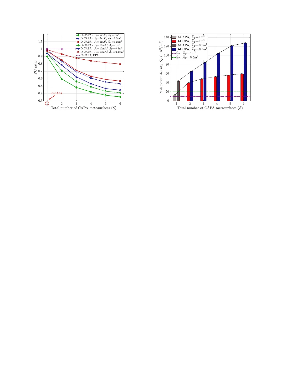
Distrib uted Continuous Aper ture Arrays f or Multiuser SWIPT Muhammad Zeesha n Mumtaz, Mohammadali Mohammadi, Hien Quoc Ngo, a nd Michail Matthaiou Centre for W ireless Innovati on (CWI), Queen’ s Uni versity Belfast, U.K. Email: { mmumtaz01, m.mohammadi, hien.ngo, m.ma tthaiou } @qub .ac .uk Abstract —This paper pro poses a distributed continuous aper- ture array (D-CAP A) to support simultaneous wireless infor - mation and power transfer (SWIP T ) to multip le information users (IUs) and energy users (EUs). Each metasurface sup- ports continuous surface curr ents that radiate electro magnetic (EM) wa ves for in fo rmation an d energy transmission to the users. These wav es propagate t h rough conti n uous EM chann els characterized by the dyadic Gre en’ s function. W e f ormulate a system power consumption (PC) min imization problem subject to spectral efficiency and energy harvesting quality-of-service ( QoS) requirements, where the QoS requirem ents are deriv ed und er the equal power allocation (EP A) scheme. An efficient t wo-layer optimization algorithm is developed to solve this problem by optimizing the powe r allocation subject to the QoS violation penal- ties using augmented Lagrangian transformation. Our numerical results show th at well-optimized current distributions ov er each metasurface in the proposed D-CAP A achiev e up to 65% and 61% reductions in overa ll system PC compared to the EP A and co-located CAP A (C-CAP A) cases, while maintaining the same total aperture size and transmission power . Index T erms —Contin uous aperture array (CAP), power con- sumption (PC), simu ltaneous wireless inform ation and power transfer (SWIPT). I . I N T RO D U C T I O N Continuou s-aperture array (CAP A) transcei vers synthesize continuo us cur rent distributions b y replacing spatially discrete arrays (SPDAs ) with a field-c e n tric manifestation that emu lates the classical Max w e ll’ s EM propag ation mo del [1], [2]. By manipulatin g these cur rent distributions over the p hysical aper- ture, CAP A architectures un lo ck precise energy focu sing and enhanced spatial d egrees o f freedo m com pared to the e le m ent- spaced a r rays of com p arable size [ 3], [ 4]. T h ese uniq ue func- tionalities translate into lo w e r system PC as the transmitted energy is ac curately concen tr ated o n the network user locations with red uced spillover . The EM field-based in te r pretation, that underpins the energy- focusing capability of CAP As, enables u s to pursue SWIPT This work was support ed by the UK E nginee ring and Physical Sciences Researc h Council (EPSRC) grant EP/X04047X/ 2 for TIT AN T elecoms Hub . The work of H. Q. Ngo was supported by the U.K. Research and Innov ation Future Leaders Fellowshi ps under Grant MR/X010635/1 , and a research grant from the Department for the Economy Northern Ireland under the US-Ireland R&D Part nership Programme. This work was supported by the E uropean Researc h Council (ERC) under the European Union’ s Horizon 2020 research and innov ation programme (grant agree ment No. 101001331). M. Z. Mumtaz is also with the Colle ge of Aeronautic al Engineering , Nationa l Uni versity of Scie nces & T echnology (NUST ), Pakistan, (email: zmumtaz@c ae.nust.edu.pk). in commu nication networks [ 5]. In particular, b y effecti ve utilization of these pr opagation character istics, the c urrent distributions over these metasurfaces can be exploited in a manner to a c h iev e EM signal concen tration for both EUs and IUs, while mitigatin g inter-user-interference (IUI) fo r I Us with aggressive sidelo be sup pression [6] . Recently , CAP A technology has attracted significant resear ch interest, including the hardware imp lementation of shared aper- ture metasurfaces [7] . Howe ver, most of the rela ted works hav e considered the c ase of a single CAP A sur face for p roviding services in commu nication networks. I n [8], W ang et a l. c o n- ceiv ed the optimal beamform ing desig n s for a multiuser single- CAP A system with the aim of p ower minimizatio n. The authors also demo nstrated its super ior perfo r mance again st the SPD A variant. In [9 ] , the au thors av ailed of the c a lculus of variation (CoV) techn ique to handle the continu ous na tu re of the ene rgy distribution over a CAP A surface fo r a multigro up mu lticast network, while substantially improving the energy efficiency (EE). Similar ly , metasur face-based ho lograph ic MI M O (H- MIMO) was considered in [5 ] for suppo rting integrated data and energy transfer by using finite-item Fourier series approx - imation for the continuou s beam forming function s. Howev er , these studies d o no t address the effects of distributed arch itec- tures on the PC reductio n. For the given overall apertu r e size and transmission power of the CAP A metasurfaces, we assess the pe r forman ce g ains of spatially D- CAP A over its C-CAP A c o unterpa rt. The m ain contributions of this paper are as follows: • W e propose a D-CAP A system that delivers SWIPT ser- vices using continuou s transmission-current signals over dyadic Green’ s function - b ased EM channels for both IUs and EUs. Th is architectu re e n ables p recise EM wav e manipulatio n across spatially distributed metasur faces, thereby enhancin g both energy transfer efficiency a n d commun ication performan c e. • A dual-routine optimization framew ork is developed to addr ess the PC minimization pr oblem while ensur- ing complian ce with th e bench mark spectral-efficiency (SE) and harvested-energy (HE) QoS requirem ents. T he propo sed method employs the limited-memory Broy- den–Fletche r–Goldfarb– Shanno algorithm with boun d constraints (L-BFGS-B) to optimize p ower allocatio n, while an augmented-Lagrangian (AL) mech a n ism is used to man age Qo S constrain t violation s. • Our nu merical simulation results verify a substan tial re- duction in the collective PC o f the considered o ptimized D-CAP A system in c omparison to the C-CAP A case. This p erform ance enhanc e ment is attributed to the pre- cise b eamform ing ca p ability ac h iev ed due to the fo cused energy zones over the continuou s metasurfaces by the propo sed optimization techn ique. Notations: W e u se bold lower case and up per case letters to denote vectors an d matrices, respectively . The superscrip ts ( · ) ∗ , ( · ) T , a nd ( · ) − 1 denote the conjugate, transpo se, and in verse of a matrix, re sp ectiv e ly ; I N represents the N × N identity matr ix ; k · k return s the n orm of a vector; E {·} rep resents the statistical expectation. Finally , ∇ f ( · ) pe r forms the gradient o peration on a f unction f ( · ) . I I . S Y S T E M M O D E L W e co nsider a multi-metasurface system in volving S spa- tially distributed co ntinuou s aperture a r rays which are indexed by s ∈ S = { 1 , . . . , S } , each having an ef fectiv e aperture S ( s ) T with occu pied area A ( s ) T = |S ( s ) T | = ¯ A T /S , wh ere ¯ A T is the constant to tal aper ture. It is further assum e d that each metasurface is capable to synthesize any curren t distribution posed on its aperture. The downlink operation of these surfaces simultaneou sly serves K = L + M users, repr esented b y the un ion set U = D ∪ E . Here, D = { 1 , . . . , L } denotes the IUs, while E = { 1 , . . . , M } d enotes the EUs. Now , the network to p ology is ba sed o n uniform ly distributed CAP A surfaces with cen ter location s c s ∈ R 3 × 1 . Moreover, the K users are un iformly distributed in the three-dim e nsional (3-D) space surro unding the distrib u ted CAP A surfaces, which ar e located on th e plane z = 0 . A. CAP A T ransmission S ignal an d P ower Con straints Each CAP A sur face operates with contin uous current signals which is the sup e rposition of cu rrent distributions intended fo r each user stream [5 ] . For the CAP A surface s , this pheno menon can b e mathem atically represen ted as J s ( u , Ω ) = X K j =1 Ω sj θ sj ( r j , u ) x sj , (1) where Ω sj ∈ Ω is the wa ve a mplitude which serves as the cor- respond in g P A coefficient, w h ile Ω denotes the matrix of all the P A coefficients; x s = [ x s, 1 , . . . , x s,L , x s,L +1 , . . . , x s,L + M ] T ∈ C K denotes the transmission symbo l vector f ollowing a unit- variance Gaussian distribution, while satisfying the conditio n E { x s x H s } = I K ; θ sj ( r j , u ) , ∀ u ∈ S ( s ) T , is the beamf ormer at- tributed to the current d ensity componen t fo r the mo dulation of symbol x sj intended for user j located at position r j ∈ R 3 × 1 . Additionally , this composite transmitted signal is bounde d by the available power budget at eac h CAP A surface a s Z S ( s ) T k J s ( u , Ω ) k 2 d u ≤ P s , (2) where P s = P t /S is th e maximu m tr ansmit p ower av ailab le at each sur face out of th e overall CAP A system power P t . B. EM Chan nel Model The superimp osed electric field e ( r ) at a position r = ( r x , r y , r z ) ∈ R 3 × 1 can be o btained as [10 ] e ( r ) = X S s =1 Z S ( s ) T G s ( r , u ) J s ( u , Ω ) d u , (3) where G s ( r , u ) ∈ C 3 × 3 is the dya d ic f ree-space Green’ s function used to char acterize the chan n el matrix fro m th e surface aper ture u ∈ S ( s ) T to the user location r k , given by G s ( r , u ) = j κZ 0 4 π e j κ k p k k p k h I 3 − ˆ p ˆ p H + j κ k p k I 3 − 3 ˆ p ˆ p H + 1 ( κ k p k ) 2 I 3 − 3 ˆ p ˆ p H i , (4) where p = r − u , with th e u nit vector defined as ˆ p = p / k p k , κ = 2 π / λ is the characteristic wav e number with λ bein g the carrier wa veleng th, while Z 0 represents the free-space impedanc e. The three difference terms in the d e finition o f the Green’ s function relate to the far -field, the middle-field and the near-field EM radiatio n region s. Con sider this function , the continuo us EM chann el from the sur face s to a cer tain user k can be defined by using the co- polar comb ining comp o nents of th e tr i- polarized CAP A framework as h sk ( u ) , ˆ i T k G ( r k , u ) ˆ i s + ˆ j T k G ( r k , u ) ˆ j s + ˆ k T k G ( r k , u ) ˆ k s , ( 5) where h ˆ i s , ˆ j s , ˆ k s i and h ˆ i k , ˆ j k , ˆ k k i are unit vectors fo r the CAP A transmission surfaces and receptio n antennas, r espectiv ely . C. B eamforming Design The continuo us-apertu re fo rmulation allows us to sy nthesize user-specific current distrib utions associated to the beamfo r mer θ sj ( r j , u ) over the span of the co ntinuous E M channels h sk ( u ) . Math ematically , these beamf o rmers are defin e d as θ sj ( r j , u ) , θ sj ( u ) ˆ p w ith nor malized coefficients given θ sj ( u ) = P K k =1 b j k h sk ( u ) q b H j A ( s ) b j , (6) where A ( s ) , [ A ( s ) kk ′ ] k,k ′ ∈ C K × K denotes the full-rank channel correlation m atrix whose in dividual elements encode the cor- relation of c h annel realizatio ns induced on th e CAP A sur face, defined as [ 11, Eq. (6)] A ( s ) kk ′ , Z S ( s ) T h sk ( u ) h ∗ sk ′ ( u ) d u . (7) Note that, b j in (6) repre sents the pr e coding vectors, which can be designed by utilizing linear tech niques, i.e. , regularized zero-fo rcing ( RZF) an d maxim u m ratio transmission (MR T) f or the IUs and EUs, respe c ti vely . For RZF preco ding, we extract the IU block fr om the composite chan nel cor relation matrix as A L ⊂ P S s =1 A ( s ) ∈ C L × L , which is u sed to con struct the matrix B L = ( A L + α ZF I L ) − 1 , whose column elements are used as IU precodin g coefficients b j . The regularization factor α ZF > 0 trades b etween conventional ZF and MR T func tion- alities. On the oth er hand, the EUs emp loy the MR T techn ique derived from vector b j = e j , where e j is the can onical b asis vector with e j m = δ j m . These MR T co efficients perfectly align the incident energy strea m s to the corr esponding EM channels. D. Received Sig nal Each user can b e assumed as a point in the 3-D radiatio n space of the CAP A transmission system, since the effecti ve aperture o f th e r eceiv er is negligible in comp arison to the transmission f ramework, i.e., A R = λ 2 / 4 π ≪ A ( s ) T . T he user k located at the position r k receives the signal ( from (3)) y k = S X s =1 Ω sk x sk J sk ( G , θ ) + K X j 6 = k Ω sj x sj J sj ( G , θ ) + n k , (8) where the fu nction J sk ( G , θ ) = R S ( s ) T L sk ( G , θ ) d u is de- fined over the continu ously dif ferentiable f unction giv e n as L sk ( G , θ ) = ˆ i T k G ( r k , u ) θ sk ( u ) ˆ i s + ˆ j T k G ( r k , u ) θ sk ( u ) ˆ j s + ˆ k T k G ( r k , u ) θ sk ( u ) ˆ k s . Moreover, n k represents the EM noise with zero -mean Gau ssian distributed entr ies n k ∼ C N (0 , σ 2 ) . E. Downlink SE and HE A nalysis For a giv en IU l , the co rrespond ing signal-to-interf erence- plus-noise ratio (SINR) can be derived from (8 ) as Γ l ( G , θ , Ω ) = P S s =1 Ω 2 sk |J sk ( G , θ ) | 2 P S s =1 P K j =1 ,j 6 = k Ω 2 sj |J sj ( G , θ ) | 2 + σ 2 k . (9) According ly , the achievable SE (in bit/s/Hz) can be ex- pressed as R l = log 2 (1 + Γ l ( G , θ , Ω )) . (10) The p ower density incident o n th e anten na o f a EU receiv er m c a n be ev alu a ted as S ( G , θ , Ω ) = 1 2 Z X S s =1 X K j =1 Ω 2 sj |J sj ( G , θ ) | 2 , (11) where Z is the wave impedance of the receiver . Using the Poynting’ s the o rem, the RF power harvested at EU m can b e derived as Q m ( G , θ , Ω ) = Z S ( s ) T S ( G , θ , Ω ) ˆ η · d u = A R cos ϕ m 2 Z X S s =1 X K j =1 Ω 2 sj |J sj ( G , θ ) | 2 , (12) where ˆ η represen ts the norm al vector to the rec ei ver antenna, while ϕ m ∈ [0 , π / 2] d enotes the including angle b etween ˆ η and th e Poynting vecto r at the m -th u ser lo cation. The practical implemen tation of EH corr esponds to th e n on- linear h arvesting energy (NL-HE) Q NL m , w h ich can be modeled using th e following logistic fun ction [12] Q NL m ( G , θ , Ω ) = Q max ς 1 + e − a ( Q m ( G , θ , Ω ) − b ) − ζ , (13) where ς = e ab / (1 + e ab ) and ζ = Q max /e ab with a and b are the EH rectifier param eters, while Q max denotes the satu r ation power of this rectifier circu it. I I I . P O W E R C O N S U M P T I O N M I N I M I Z A T I O N D E S I G N A. Optimization Pr oblem F ormulation The goal of the optimizatio n p roblem is to minimiz e the overall system PC with respect to the beamf ormers, while ensuring that th e SE and H E QoS re quiremen ts—deriv ed from the EP A bench mark—are satisfied fo r all users associated with each CAP A surface. Mathem a tically , this optimization problem with continuo us integra l functio n s-based Qo S constraints can be fo rmulated as min { Ω } X S s =1 X K j =1 Ω 2 sj (14a) s.t. Γ l ( G , θ , Ω ) ≥ Γ EP A l , ∀ l = 1 , 2 , . . . , L , (14b) Q m ( G , θ , Ω ) ≥ Q EP A m , ∀ m = 1 , 2 , . . . , M , (14c) X K j =1 Ω 2 sj ≤ P s , ∀ s = 1 , 2 , . . . , S. (14d) For (14a ) and (1 4d), it is assumed that the beamform e rs satisfy the c ondition R S ( s ) T k θ sj ( r j , u ) k 2 d u = 1 . Moreover, the threshold SE ( Γ EP A l ) and HE ( Q EP A m ) in (1 4b) and (14c) have been computed fo r th e EP A case by using the P A coefficients Ω EP A sj = P t / ( S K ) . B. A ugmented- Lagrangian Optimization F ramew ork Considering the o ptimization problem in (1 4a), we lev er- age the AL assist ed quasi-Newton method based L-BFGS-B approa c h [13], [14]. This pro blem ca n be transformed into a finite sum minim ization pro blem by employing the AL approa c h , which combin es the continu ous co nstraint functions in (14 b) and (14c ). Mathematically , this AL transform a tion c an be de fin ed with respect to the P A coefficients choices ( Ω ) as f ( Ω ) , S X s =1 K X j =1 Ω 2 s,j + λ T SE v SE ( G , θ , Ω ) + ρ 2 v SE ( G , θ , Ω ) 2 | {z } IU SI NR penalties + β λ T EH v HE ( G , θ , Ω ) + ρ 2 v HE ( G , θ , Ω ) 2 | {z } EU HE penalties , (15) where, v SE ( G , θ , Ω ) = Γ EP A − Γ ( G , θ , Ω ) and v HE ( G , θ , Ω ) = Q EP A − Q ( G , θ , Ω ) represent the in equality residual vecto rs for I U SINR and E U HE EP A targets, which are arrang ed as Γ EP A and Q EP A , respectively; ρ is the AL penalty; λ SE and λ EH are the Lagran ge multiplier s, and β > 0 balances the IU an d EU pe nalties conside ring the c o rrespon d ing signal power differences. For the box constraints 0 ≤ Ω s,j ≤ √ P s , we use the L-BFGS-B technique to com pute the pro jected quasi-Newton steps of the fo r m Ω t +1 = Π [0 , √ P s ] Ω t + α t p t , (16) with search direction d efined a s p t = − H t ∇ f ( Ω t ) , while Π [0 , √ P s ] ( Φ t ) = a rg min Ω ∈ R + {k Ω t − Φ t k} projects the term Φ t = Ω t + α t p t to the closest p oint within the feasible inter val using E uclidean no rm. Here, ∇ f ( Ω t ) ∈ R S × K represents the gra dient of th e Lagrang ian function defined in ( 15) ca lc u lated for th e step t . As both SE ( Γ ) and HE ( Q ) are co mbination s of continuou s in- tegral function s with linear depe n dence on the P A coefficients, the Lang rangian function in (1 5) can be d ifferentiated using the cha in rule. Each e le m ent of ∇ f ( Ω ) can be represented as partial d eriv ative w ith respect to a particular P A v ariable Ω s,j as ∂ f ( Ω ) ∂ Ω s,j =2 Ω s,j − X L l =1 w l ∂ Γ l ( G , θ , Ω ) ∂ Ω s,j − X M m =1 u m ∂ Q m ( G , θ , Ω ) ∂ Ω s,j , (17) where, w l , λ SE ,l + ρ v SE ,l and u m , λ HE ,m + ρ v HE ,m , while v SE ,l ∈ v SE ( G , θ , Ω ) and v HE ,m ∈ v HE ( G , θ , Ω ) are the ineq uality re sid u als for IU l and E U m , respectively . The partial deriv ative of the SE component can be derived using the der iv ative q uotient rule as ∂ Γ ∂ Ω s,j = 2 Ω s,l |J sl ( G , θ ) | 2 P S s =1 P K j =1 ,j 6 = l Ω 2 sj |J sj ( G , θ ) | 2 + σ 2 l , j = l , 2 Ω s,j |J sj ( G , θ ) | 2 P S s =1 Ω 2 sl |J sl ( G , θ ) | 2 P S s =1 P K j =1 ,j 6 = l Ω 2 sj |J sj ( G , θ ) | 2 + σ 2 l 2 , j 6 = l . (18) Now , the partial deriv ati ve of the HE component can be giv en as ∂ Q m ( G , θ , Ω ) ∂ Ω s,j = 2 A R cos ϕ m Ω sj |J sj ( G , θ ) | 2 2 Z . (19) Substituting the expression s in ( 18) and (19 ) in (17), we ob - tain the c losed-for m expre ssion fo r the gradient o f Lagrangian function in (20 ) at the top of the n ext page. On th e other hand, the m a trix H t in (16) represents a semi- positive definite limited-mem ory approxima tio n fo r in verse- Hessian ∇ 2 f ( Ω t ) − 1 constructed fr om the last q curvature pairs { ( s i , y i ) } t − 1 i = t − q in ord e r to av o id intense c o mputation al requirem ents fo r second order deriv a tives. This appr oximation ev aluates the BDFS updates using the following relatio nship [13, Eq . (6) ] , H t +1 = I q − s t y T t y T t s t H t I q − y t s T t y T t s t + s t s T t y T t s t , (21 ) where, s t , Ω t +1 − Ω t and y t , ∇ f ( Ω t +1 ) − ∇ f ( Ω t ) are the differentials of the successiv e P A upd ates an d the g radients of their Lagrang ian f unction, which is calculated by using th e above closed-form expression in (20 ). C. Du al-Rou tine Optimization Algo rithm Now , we discu ss the dual-routine op timization structure which compu tes the P A co e fficient up dates ( Ω ) using the L- BFGS-B method ( in ner iter ation) and th e L agrange m ultiplier updates for AL-f u nction (outer iteration ), alternatively . 1) L-B FGS-B Up date Ro utine: For a particular inn e r iter- ation t , we generate the generalized Cauchy point ( Ω c t ) by following the steepest fea sib le direction ∇ f ( Ω t ) until the bound s [0 , √ P s ] a re reac h ed. Then, we perform sub space minimization b y app lying L -BFGS-B two-loop recursion [15, Algorithm 7.4], wh ile using dua l search dir ections ( ± p t ) for the Newton step in (16 ). Additiona lly , the pr o jected line-search function is d e fined as φ ( α t ) = f ( Π [0 , √ P s ] ( Ω c t − α t p t ) , which is used to perfor m b a c ktracking search to obtain line-searc h step size α t > 0 . Based on these updates, we evaluate the next P A estimate Ω t +1 and utilize it to up date the feasible curvature pair ( s t , y t ) an d limited-memor y Hessian H t based on the last q curvature pairs stored tem porarily . The initial choice of th is Hessian m atrix is set as H (0) t , s T t − 1 y t − 1 k y t − 1 k 2 I q . It is impo r tant to note that the upd ate step is require d to satisfy the curvature condition y T t s t > 0 , which is regulated by AL penalty terms. Th e inner routine terminates as either the step size s t < δ or grad ient size y t < δ with toleran ce level δ . 2) AL Upda te Routine: During th e iteration u , the ou ter routine updates the Lagra nge multipliers λ SE , λ HE , subject to the QoS constrain t violations. Mathe matically , this can be represented as: λ u +1 SE = λ u SE + ρ v u SE , ( G , θ , Ω ) , (22a) λ u +1 SE = λ u HE + ρ v u HE ( G , θ , Ω ) , (22b) where the QoS violations fo r a particular iteration u are ca lcu lated as v u SE ( G , θ , Ω ) = ma x( Γ EP A ( G , θ , Ω ) − Γ ( G , θ , Ω ) , 0 ) and v u HE ( G , θ , Ω ) = max( Q EP A ( G , θ , Ω ) − Q ( G , θ , Ω ) , 0) . If the max imum of these vio lation criter ia v max = max {k v SE k , k v EH k} redu ces below th e feasibility tolerance ǫ ≥ 0 , the algo rithm conv e rgen ce is achieved. In the ev ent of non - conv ergence, the AL penalty weig ht ρ a d dresses the constrain t violations adaptively over the successive AL- iterations. By adop ting an aggressive policy , we d ouble this parameter for the n ext AL- iteration u + 1 as ρ u +1 = 2 ρ u . The steps o f this pro cess are presented in Algo rithm 1 . Complexity a nalysis: The e xecutio n of the L-BFGS-B routine inv olves the calculation of finite difference gradient ∇ f ( Ω t ) and limited memory Hessian matrix H t , inc urring per- iteration complexity of O ( S K 2 ) and O ( q S K ) , respecti vely . On the other hand, AL routine evaluates QoS violations with complexity of O ( S K 2 ) . Hence, the overall com putational complexity can be gi ven as O ( U ( S 2 K 3 T ( K + q )) for T inner and U ou ter iterations. I V . N U M E R I C A L R E S U LT S In this sectio n, the performance of the D-CAP A m eta- surface fr amew ork with the p roposed optimization algorithm is evaluated. W e have considered S ∈ { 1 , . . . , 6 } m ultiple metasurfaces which serves K = 2 0 to tal users inclu ding L = 14 IUs and M = 6 EUs. Figure 1 depicts a rando m realization of the pro posed CAP A metasurfaces fram ew o r k with D-CAP As shown as blue squar es, while the C-CAP A as grey squa re. T hese surfaces ar e rand omly positioned on the xy -plane ( x, y ∈ [ − 10 , 10] m , z = 0 ) with the IUs (green dots) scattered in region z ∈ [0 . 5 , 20 ] m . The EUs (red d ots) are located in small xy -areas ( dashed blue squares) arou nd the D-CAP As in region z ∈ [0 . 5 , 2] m. For fair an alysis over multiple surface choices, we have con sid e red constant total aper ture area ¯ A T = { 0 . 25 , 0 . 5 , 1 } m 2 with total system transmission power fixed at P t = { 5 , 10 } mA 2 [8]. This cor r oborates the fact that the sam e ap erture area and transmit power co nsidered fo r the C-CAP A is further divided into mu ltiple distributed surfaces, A ( s ) T = ¯ A T /S , P s = P t /S . The system carrier wa velength is fixed at λ = 0 . 1 m , while the free-space chann e l imp edance Z 0 and the EU receiver impedanc e Z ar e set to 120 π Ω and 25 Ω , respectiv ely . The noise power at each user receiver is σ 2 = 10 − 9 A 2 . The NL-HE para m eters are selected as Q max = 24 mW , while ∂ f ( Ω ) ∂ Ω s,j =2 Ω s,j − 2 w l Ω s,l |J sl ( G , θ ) | 2 P S s =1 P K j =1 ,j 6 = l Ω 2 sj |J sj ( G , θ ) | 2 + σ 2 l + L X l =1 ,j 6 = l Ω s,j |J sj ( G , θ ) | 2 P S s =1 Ω 2 sl |J sl ( G , θ ) | 2 P S s =1 P K j =1 ,j 6 = l Ω 2 sj |J sj ( G , θ ) | 2 + σ 2 l 2 ! − X M m =1 2 u m A R cos ϕ m Ω sj |J sj ( G , θ ) | 2 2 Z , (20) Algorithm 1 AL + L- BFGS-B for P A optim ization 1: Initialization: Set iteration indices t = 0 , u = 0 ; initial P A estimates Ω 0 = P t / ( S K ) ; Lagran ge multiplier s λ SE , λ HE ; AL pen alty ρ > 0 ; I U/EU balancing factor β > 0 ; f easibility thre sholds δ = 0 , ǫ > 0 . 2: AL Routine: 3: repeat 4: Define f ( Ω ) as in (15) with current λ SE , λ HE , ρ . 5: Set inner iterate Ω ← Ω u . Initialize limited- memory pairs { ( s i , y i ) } for L -BFGS-B ap p roach. 6: L-BFGS-B Routine: 7: repeat 8: Comp ute gradien t ∇ f ( Ω t ) u sin g (20 ). 9: Follow the steepest direction ∇ f ( Ω t ) to the bo u nds [0 , √ P s ] , ob taining generalized Cauch y point Ω c t = Π [0 , √ P s ] ( Ω t − α ∇ f ( Ω t )) . 10: App ly th e two–loop L-BFGS re cursion to g e t the quasi-Newton direction p t = − H t ∇ f ( Ω c t ) . 11: Define the pr ojected line-sear ch function φ ( α t ) = f Π [0 , √ P s ] Ω c t + α t p t and per form a back tracking search to g et α t > 0 . 12: Upd a te P A e stima te : Ω t +1 = Π [0 , √ P s ] Ω c t + α t p t . 13: Upd a te curvature pair: s t = Ω t +1 − Ω t , y t = ∇ f ( Ω t +1 ) − ∇ f ( Ω t ) . 14: if y T t s t > 0 : 15: Store the f easible cur vature pair ( s t , y t ) 16: Update the limited- memory inverse-Hessian H t 17: else continue 18: Inc r ement inner iteration index t = t + 1 . 19: until k s t k ≤ δ or k y t k ≤ δ . 20: Ev aluate violation s: v SE ( G , θ , Ω u +1 ) = max Γ EP A − Γ ( G , θ , Ω u +1 ) , 0 , v HE ( G , θ , Ω u +1 ) = max Q EP A − Q ( G , θ , Ω u +1 ) , 0 . 21: Lagrange multiplier upd a te : λ SE ← λ SE + ρ v SE , λ HE ← λ HE + ρ v HE . 22: Increase pen alty: ρ ← 2 ρ . 23: Increment ou ter iteration index u = u + 1 . 24: until max {k v SE k , k v HE k} ≤ ǫ . 25: Return: Ω ⋆ = Ω u +1 . the rectifier pa r ameters as a = 150 0 , b = 0 . 0022 [12]. Th e optimization convergence thresholds are fixed as δ = 10 − 9 and ǫ = 10 − 3 . For the L-BFGS-B routine, we store only the q = 10 last curvature pair s for Hessian app roximation , while the AL routine sets the initial pena lty weight and IU/EU b alancing factor as ρ 0 = 20 an d β = 10 , respectively . In ord er to an alyze the comparative advantage of th e D- Fig. 1: C-CAP A and D-CAP A network layouts (single random real- ization). CAP A structure with th e proposed du al-routine optimiza tion algorithm , we consider the PC ratio against the benchmark EP A case. In this regard , this metric has been analyzed in Fig. 2 for multiple number o f metasu r faces ( S ) including b oth C-CAP A ( S = 1 ) and D-CAP A ( S = { 2 , 3 , 4 , 5 , 6 } ) cases, while considering different ch o ices of ¯ A t and P t . I t can be clearly no ticed here th a t the PC ratio red uces p rogressively with an increasing nu mber of CAP A surfaces, while satisfy ing the IU SE and EU H E Qo S benc h marks. This observation can be attributed to the smaller distances between the CAP A surfaces and the spatially distributed users, even thou gh the aperture area and transmission p ower for ea ch D-CAP A decr eases lin- early . For the C-CAP A case, we can observe that our pro posed optimization algor ithm reduces the PC up to 10% against th e non-o ptimized EP A case (d otted purple line). On the oth er hand, this re d uction is up to 6 5% and 61 % for the D- CAP A for th e S = 6 scenario with respect to EP A and op timized C-CAP A counterparts, respectively . W e have also analyzed the ef fect of different total trans- mission p ower P t = { 5 , 10 } mA 2 (dotted an d solid lines), along with the aperture sizes ¯ A T = { 0 . 25 , 0 . 5 , 1 } m 2 (red, blue an d gr een line s). Figure 2 demo nstrate that a larger to tal aperture size with higher transmission power re su lts in the most effecti ve perfo r mance for our proposed optimization algo rithm shown by the solid green line. Most importantly , a decreased transmission p ower ha s more dr astic effect on the PC reduction. For example, we can notice a 40% p erform a nce reduction for the case of P t = 5 mA 2 , ¯ A T = 0 . 2 5 m 2 (dotted red line) in compariso n to P t = 10 mA 2 , ¯ A T = 0 . 25 m 2 (solid red line). Now , we examine the peak transmission power density ( ˆ S T ) as the numb er of D-CAP As in c r eases (color ed bars) alon g with the C-CAP A (grey bars) case in Fig. 3, assuming a constant P t = 10 mW 2 . This analysis also evaluates the impact of Fig. 2: PC ratio v ersus the number of CAP A surfa ces. the overall CAP A aperture size ¯ A T = { 0 . 5 , 1 } m 2 , sho wn as red and blue bars, respectively . T he proposed dual-routine optimization framew o rk focuses the tran smission current distri- bution by ef ficiently manip u lating the wa ve amplitude s with out compro mising on the SE and HE r e q uiremen ts, thus, leading to concentr a ted energy ’ h ot-spots’ over the m etasurfaces. For the C-CAP A case, we observe that ˆ S T increases by 32% and 120 % for ¯ A T = 0 . 5 m 2 and ¯ A T = 1 m 2 , respectiv ely , compared with the EP A b enchmar ks, whose average power densities ¯ S T are sho wn as the purple and green dotted horizontal lines. Moreover , the energy focusin g becomes substantially stronger in the D-CAP A configuratio n , achieving up to a six- fold im p rovement f or S = 6 compared with the EP A case. This pr o noun c e d power co ncentratio n over specific r egions of the CAP A sur face can be attr ibuted to the selective spatial EM visibility acr oss d ifferent areas o f the metasur face, which guides the beam f orming design to conc e n trate user-specific current d istributions onto particular ph ysical zo n es of the transmitter . Anothe r key observation is that ˆ S T decreases as the overall aper tu re size ¯ A T increases from 0 . 5 m 2 to 1 m 2 , shown b y the red and blue bars, re sp ectiv e ly . Th is implies that for larger ap ertures, the same tr ansmission p ower is spr ead across a wider phy sical area of th e m etasurface. V . C O N C L U S I O N This paper in vestigated a distributed CAP A (D-CAP A) archi- tecture for m ultiuser SWIPT and developed an optimizatio n framework to minimize system PC und er SE and HE QoS constraints der iv e d fr om the EP A ben chmark. By explo it- ing con tinuous current-signal synth esis and dy adic Green’ s function –based chan nels, the propo sed framework applies the L-BFGS-B me thod to o ptimize the P A co efficients and le ver- ages an AL scheme to ma n age Qo S constraint violations. Sim- ulation resu lts de m onstrate that the op timized D-CAP A design achieves up to a 6 % reduction in system PC compared with an optimized C-CAP A configu ration, sh owcasing the stro ng EM beamfor ming cap abilities of CAP A transmit surfaces. Future work m ay explore selective user– m etasurface association and adaptive acti vation of D -CAP A surfaces to further en hance EE. Fig. 3: Peak po wer density versus t he number of CAP A surfaces. R E F E R E N C E S [1] B. Zhao, C. Ouyang, X. Zhang, and Y . Liu, “Continuous-ape rture ar- ray (CAP A)-based wirele ss communica tions: Capacity charac teriz ation, ” IEEE T rans. W ireless Commun. , vol . 24, no. 12, pp. 10 456– 10 473, Dec. 2025. [2] Y . L iu, C. Ouyang, Z. W ang, J. Xu, X. Mu, and Z . Ding, “CAP A: Continuo us-apertu re arrays for rev oluti onizing 6G wireless communica- tions, ” IEEE W irel ess Commun. , vol. 32, no. 4, pp. 38–45, Aug. 2025. [3] Z. W an, J. Zhu, and L . Dai, “Can cont inuous ape rture MIMO obtain more mutual information than discrete MIMO?” IEE E Commun. Lett. , vol. 27, no. 12, pp. 3185–3189, Dec. 2023. [4] Y . Zhang, C. Ouyan g, H. Shan, Y . Liu, Y . Zhou, and Z. Shi, “Exploiting continu ous-apert ure arrays in integ rated sensing and communication systems, ” IEEE T rans. W ir eless Commun. , vol. 24, no. 11, pp. 9539– 9555, Nov . 2025. [5] Q. Huang, J. Hu, Y . Zhao, and K. Y ang, “Hologr aphic integrate d data and energy transfer , ” IEEE T rans. W irele s s Commun. , vol. 23, no. 12, pp. 18 987–19 002, Oct. 2024. [6] H. Zhang, N. Shle zinger , F . Guidi, D. Dardari, M. F . Imani, and Y . C. Eldar , “Nea r-field wirele ss po wer transfe r for 6G interne t of e very thing mobile networks: Opportunities and challen ges, ” IEEE Commun. Mag . , vol. 60, no. 3, pp. 12–18, Mar . 2022. [7] M. Sazegar et al. , “Ku-band SA TCOM user terminal with co mplete beam steering using a shared aperture m etasurf ace for full-d uple x operatio n, ” in Pr oc. IEEE EuCAP , Mar . 2023, pp. 1–3. [8] Z. W ang, C. Ouyang, and Y . Liu, “Optimal beamforming for multi- user continuous ape rture array (CAP A) systems, ” IEEE T rans. Commun. , vol. 73, no. 10, pp. 9207–9221, Oct. 2025. [9] M. Qian, X. Mu, L. Y ou, and M. Matthaiou, “Conti nuous aperture ar- ray (CAP A)-based multi-group multicast communica tions, ” IEEE T rans. Commun. , vol. 74, pp. 3787–3801, 2026. [10] Z. W ang, C. Ouyan g, and Y . Liu, “Beamforming optimizat ion for continu ous aperture array (CAP A)-based communica tions, ” IEEE T rans. W ir eless Commun. , pp. 5099–5113, Mar . 2025. [11] C. Ouyang, Z . W ang, X. Zhang, and Y . Liu, “Linear recei ve beamforming for CAP A systems, ” IEEE T rans. W ir eless Commun. , vol. 25, pp. 1030– 1047, 2026. [12] M. Z. Mumtaz, M. Mohammadi, H. Q. Ngo, and M. Matthai ou, “Near- field ener gy harvesting using XL-MIMO ove r non-stationary channels, ” IEEE W ireless Commun. Lett. , v ol. 14, no. 9, pp. 2922–292 6, Jun. 2025. [13] R. Z hao, W . B. Haskell, and V . Y . F . T an, “Stochast ic L-BFGS: Improv ed con ver gence rate s and practical acc elera tion strate gies, ” IEEE T rans. Signal P r ocess. , vol. 66, no. 5, pp. 1155–1169, Mar . 2018. [14] J. Zhang, H. L iu, A. M.-C. So, and Q. Ling, “V ariance -reduce d stochastic quasi-Ne wton methods for decentra lized learning, ” IE EE T rans. Signal Pr ocess. , vol. 71, pp. 311–326, Feb . 2023. [15] J. Nocedal and S. Wright , Numerical Optimi zation . Sprin ger New Y ork, 2006.
Original Paper
Loading high-quality paper...
Comments & Academic Discussion
Loading comments...
Leave a Comment