Design and Control of Modular Magnetic Millirobots for Multimodal Locomotion and Shape Reconfiguration
Modular small-scale robots offer the potential for on-demand assembly and disassembly, enabling task-specific adaptation in dynamic and constrained environments. However, existing modular magnetic platforms often depend on workspace collisions for re…
Authors: Erik Garcia Oyono, Jialin Lin, D
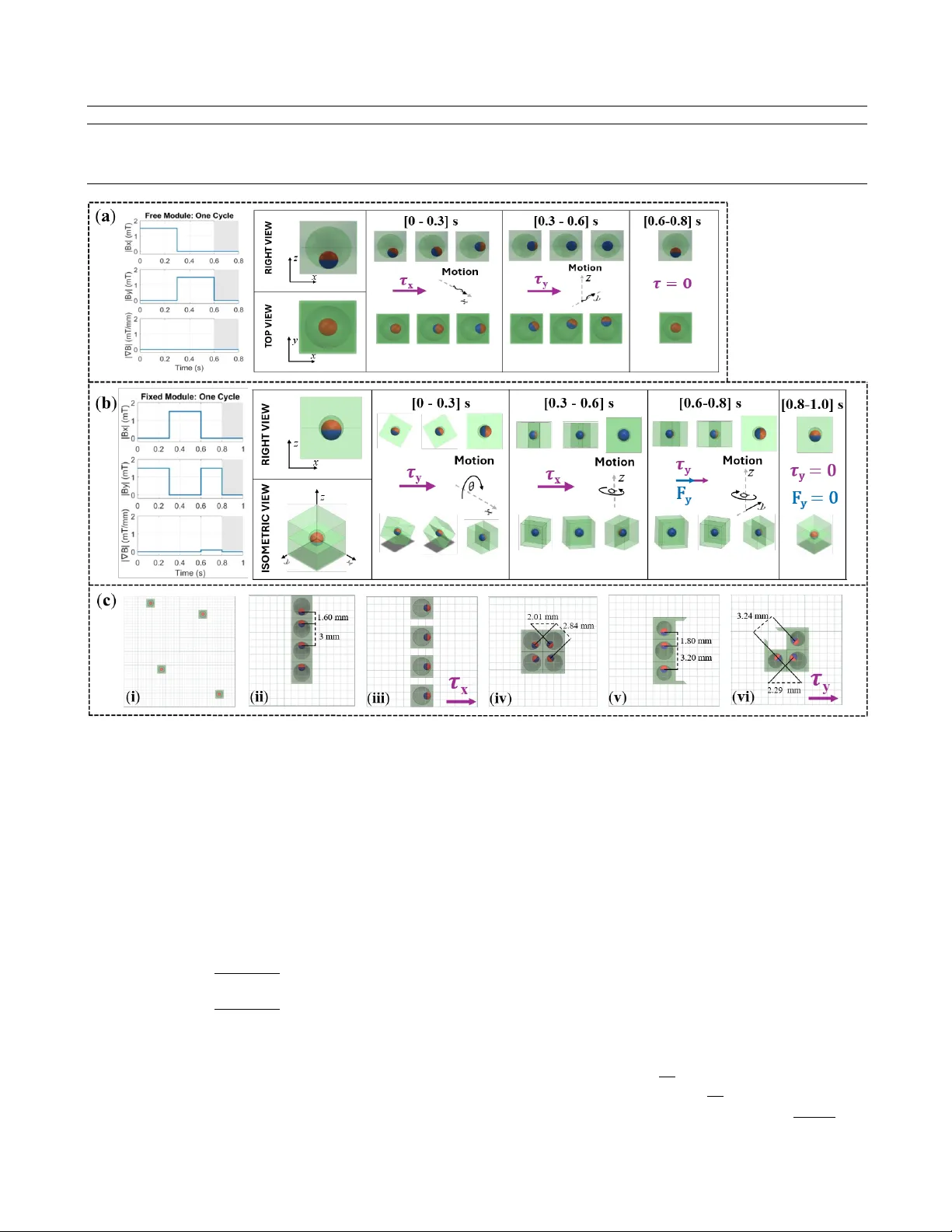
Design and Contr ol of Modular Magnetic Millir obots f or Multimodal Locomotion and Shape Reconfiguration Erik Garcia Oyono 1 † , Jialin Lin 1 † , and Dandan Zhang 1 ∗ Abstract — Modular small-scale robots offer the potential f or on-demand assembly and disassembly , enabling task-specific adaptation in dynamic and constrained envir onments. How- ever , existing modular magnetic platforms often depend on workspace collisions for reconfiguration, employ b ulky three- dimensional electromagnetic systems, and lack r obust single- module control, which limits their applicability in biomedi- cal settings. In this work, we present a modular magnetic millirobotic platform comprising three cube-shaped modules with embedded permanent magnets, each designed for a distinct functional role: a free module that supports self- assembly and reconfiguration, a fixed module that enables flip-and-walk locomotion, and a gripper module for cargo manipulation. Locomotion and reconfiguration are actuated by programmable combinations of time-varying two-dimensional uniform and gradient magnetic field inputs. Experiments demonstrate closed-loop navigation using real-time vision feed- back and A* path planning, establishing rob ust single-module control capabilities. Beyond locomotion, the system achieves self-assembly , multimodal transf ormations, and disassembly at low field strengths. Chain-to-gripper transf ormations succeeded in 90% of trials, while chain-to-square transf ormations were less consistent, underscoring the role of module geometry in reconfiguration reliability . These results establish a versatile modular robotic platform capable of multimodal beha vior and rob ust control, suggesting a promising pathway toward scalable and adaptiv e task execution in confined en vironments. I . I N T R O D U C T I ON In recent decades, small-scale robots hav e emerged as promising tools for biomedical applications, enabling mini- mally in v asi ve access and precise interaction within confined anatomical spaces [1], [2]. Their capabilities hav e been explored across di verse tasks, including in vivo diagnostics using capsule-like platforms [3], [4], site-specific drug de- liv ery [5], [6], cell and tissue manipulation [7], [8], and microsurgical procedures that demand controlled navig ation and manipulation at small scales [9]. Despite these advances, most existing systems are engineered for a single predefined function and fixed morphology . While ef fecti ve within their respectiv e domains, such task-specific designs often lack the adaptability required in complex physiological en viron- ments such as vascular networks, where a single mission may require sequential capabilities including confined-space navigation, cargo transport, and targeted manipulation. T o address this limitation, the concept of transformable modular microrobots has gained increasing attention [10], [11]. Modular robotic systems are composed of multiple 1 Department of Bioengineering, Imperial College London, London, United Kingdom. † These authors contributed equally to this work (co-first authors).*Corresponding author: d.zhang17@imperial.ac.uk Fig. 1. Conceptual overvie w of the modular magnetic millirobot platform. (a) Geometry and key dimensions of the three cube-shaped modules ( free , fixed , and gripper ), each incorporating an embedded permanent magnet with module-specific orientation. (b) Multimodal, field-programmable behaviors enabled by magnetic actuation: individual locomotion and navigation, self- assembly into chains, reconfiguration for cargo grasping/manipulation, and on-demand disassembly . interconnected units capable of dynamic reconfiguration, en- abling structural transformation in response to environmental or task demands [12]. This modular architecture supports multimodal transformations , allo wing a single robotic system to switch between different morphologies and functionalities, for example, transitioning from a streamlined configuration for navigation to an expanded or articulated structure for manipulation. Such transformability provides a pathway to- ward enhanced adaptability and multifunctionality at the microscale. Howe ver , translating modularity into biomedical microrobotics introduces substantial technical challenges. At micro- and nano-scales, the integration of onboard sensors, power sources, and actuators is severely constrained by fabrication limits and size restrictions [13]. T o address these constraints, researchers ha ve explored various e xternal wireless actuation strategies, including op- tical [14], magnetic [15], acoustic [16], electric [17], and hybrid field approaches [18]. Among these, magnetic actu- ation is particularly well suited for transformable modular microrobots. Magnetic fields provide deep tissue penetration, efficient wireless po wer transmission, and the capability to simultaneously control multiple modules without physical tethering [19]. These advantages make magnetic actuation an effecti v e foundation for coordinated assembly , disassembly , and reconfiguration in complex in viv o en vironments. W ithin the domain of magnetic modular microrobots, researchers have progressiv ely pushed modularity toward en- hanced adaptability under globally applied fields. Rogo wski et al. introduced programmable magnetic cuboid modules with embedded magnets that assemble and collaborate to transport cargo, illustrating ho w simple magnetic architecture can yield coordinated behaviors [20]. Building on this, Bhat- tacharjee et al. demonstrated open-loop shape-programmed assemblies of magnetic modules, where face magnetization and field sequences produced predictable assembled config- urations under uniform fields. Closed-loop approaches were subsequently explored by Lu et al. , who coupled visual feedback with field control to improve assembly repeatability and robustness [22]. Rogo wski et al. achieved closed-loop navigation of modular chains, adv ancing controllability of re- configurable systems and illustrating that modular assemblies can be steered in a planned manner under visual feedback and field modulation. Although these efforts represent meaningful progress to- ward controllable self-assembling and reconfigurable mag- netic systems, sev eral challenges remain. First, many re- configuration strategies rely on boundary interactions or collisions to induce morphology changes, which can be undesirable or unsafe in sensitiv e environments such as biological tissue. Second, achie ving independent control of individual modules within an assembly is dif ficult when all units are driven by the same global magnetic field. In these cases, differentiated motion is typically obtained by exploiting geometric or magnetization dif ferences between robots rather than through true addressable control, where each unit can be actuated independently under a shared input [24]. Third, the actuation infrastructure commonly used in modular magnetic robotics inv olv es complex multi-axis coil systems that must generate relatively high magnetic fields (10–40 mT) to produce usable torques and forces at millimeter scales, resulting in high po wer consumption, significant resistiv e heating, and bulk y hardware [25]. In this work, we present a modular magnetic millirobotic platform that integrates self-reconfiguration, multimodal transformations, and single-unit control under a lo w-field electromagnetic setup (Fig. 1). Unlike prior approaches that depend on boundary interactions for reconfiguration, our sys- tem enables controlled transformations through programmed magnetic field sequences, improving operational safety in constrained en vironments. The contributions of this work are as follo ws: • Develop a modular millir obotic system consisting of three complementary units ( free , fixed , and gripper ) to- gether with a hardware-efficient 2D coil setup, enabling both single-unit locomotion and cooperativ e assembly . • Demonstrate locomotion and multimodal transfor - mations under low magnetic fields ( < 13 mT), elimi- nating reliance on boundary-dependent reconfiguration. • Achieve closed-loop single-module control using vi- sion feedback and path planning, enabling adaptiv e navigation in constrained en vironments. T ogether , these advances mitigate major limitations of existing modular magnetic systems and provide a foun- dation for dev eloping versatile, scalable, and translatable millirobotic platforms for real-world applications. I I . S Y S T E M D E S I G N A. Actuation Principles Controlled locomotion and reconfiguration of the mil- lirobotic modules are achieved through the coordinated use of uniform (Helmholtz) magnetic fields and gradient (Maxwell) magnetic fields. Uniform fields primarily generate magnetic torques that align the magnetic dipole moments of the modules with the applied field direction, enabling ori- entation control and rotational motion. In contrast, gradient fields produce net magnetic forces that driv e translational motion by pulling the modules along the field gradient [26]. Beyond field-induced torque and force, magnetic dipole- dipole interactions between neighboring modules play a crucial role in system-level behavior . These interactions enable rev ersible self-assembly and controlled disassembly , allowing modules to form chains or detach in response to programmed field sequences [27]. 1) Single-Module Actuation: A magnetic dipole m placed in a uniform field B H experiences a torque τ = m × B H , (1) which tends to align the dipole with the field direction. In a gradient field ∇ B M , it additionally experiences a force F = ( m · ∇ ) B M , (2) producing translation. Intuitiv ely , the magnetization layout and mechanical con- straints of each module determine its dominant actuation mode: • F ree module: stick-slip translation. The magnet is loosely housed and can oscillate within an internal cavity . Under an oscillatory uniform-field torque, the magnet periodically contacts the cavity w alls and the substrate. This cyclic torque is rectified through fric- tional interactions, producing net stick-slip displace- ment of the module (Fig. 2(a)). • F ixed module: flip-and-walk locomotion. The magnet is rigidly embedded, so the applied torque rotates the entire cube rather than the magnet alone. Alternat- ing torque-dri v en flipping and gradient-induced biasing break symmetry and yield directional “flip-and-walk” motion (Fig. 2(b)). • Gripper module: reconfiguration-oriented docking. This module is not intended for locomotion. Instead, its magnet orientation is selected to fav or stable, per- pendicular dipole alignment during assembly , promoting reliable docking and reconfiguration (Fig. 2(c)). T ABLE I: Comparison with representati ve modular magnetic systems. System Actuation Max Field (mT) Module ( mm 3 ) Collision-free Reconfig. Single-module Closed-Loop Control W orkspace ( mm 2 ) Cooling Req. Rogowski et al. 2020 [20] 3D 40 26 × 4 × 4 – ✗ 100 × 100 ✓ Bhattacharjee et al. 2022 [21] 3D 22 2 . 8 × 2 . 8 × 2 . 8 ✗ ✗ 110 × 110 ✗ Lu et al. 2023 [22] 3D 23 2 . 8 × 2 . 8 × 2 . 8 ✗ ✗ 33 × 33 ✗ Rogowski et al. 2023 [23] 3D 32 4 × 4 × 4 – ✗ 100 × 100 ✓ This work 2D 13 3 × 3 × 3 ✓ ✓ 35 × 35 ✗ Fig. 2. Actuation mechanisms. (a) Single-module locomotion of the free module driven by uniform fields. (b) Single-module locomotion of the fixed module driv en by combined uniform and gradient fields. (c) Cuboid modules exhibit field-programmable self-organization: (i) In the absence of an external field, the dipoles align along the z -axis and the modules remain separated (“liquid” state). (ii) When brought into close proximity ( < 7 mm), dipole-dipole attraction dominates and modules self-assemble into chains. (iii) Superimposing a strong external field perpendicular to the chain direction aligns the dipoles with the applied field, suppressing chaining and maintaining separation. (iv) Appropriate field modulation yields stable “square” assemblies. (v) A chain composed of two gripper modules and one fr ee module forms through dipole–dipole attraction, creating a linear three-module assembly . (vi) Upon application of a suf ficiently strong and rapid uniform-field pulse, the weakest dipole bond in the chain is selectiv ely broken, enabling perpendicular realignment and reattachment of the modules into a functional gripper configuration. 2) Multi-Module Interactions: When multiple dipoles are present, each produces fields that affect its neighbors. For two dipoles m 1 and m 2 separated by vector r , the induced interaction force can be decomposed into radial and tangen- tial components: F r = 3 µ 0 m 1 m 2 4 π r 4 (1 − 3 cos 2 θ ) , (3) F θ = 3 µ 0 m 1 m 2 4 π r 4 (2 cos θ sin θ ) (4) where θ is the angle between the dipole axis and r . This decomposition highlights the well-kno wn “magic angle” at θ = 54 . 7 ◦ : below this angle, radial attraction domi- nates, driving chain assembly; above it, repulsion dominates, enabling separation [27]. By reorienting dipoles with e xternal fields, one can program modules to self-assemble into chains, reconfigure into new geometries, or disassemble on demand (Fig. 2(c)). B. Har dwar e Design 1) Electr omagnetic System: A two-dimensional electro- magnetic system comprising orthogonal Helmholtz and Maxwell coil pairs along the X and Y axes generates uniform fields and linear gradients (Fig. 3(a)). The magnetic field distribution can be expressed as: B ( r ) = B x B y 0 + G x − G y 2 0 0 0 − G x 2 + G y 0 0 0 − G x + G y 2 r (5) Fig. 3. Experimental and control setup. (a) T wo-dimensional electromagnetic actuation system combining Helmholtz (uniform) and Maxwell (gradient) coil pairs. (b) Planar workspace used for locomotion and assembly experi- ments. (c) Maze workspace for constrained navigation trials. (d) Photograph of the full experimental apparatus. (e) Real-time vision pipeline and live output windo ws; the software supports li ve camera processing and recording, single-image inference, and batch analysis of datasets. T ABLE II. Physical specifications of the Helmholtz and Maxwell pairs along the x - and y -axis, respectiv ely . Coil Diameter (m) Spacing (m) T ur ns Hx 0.100 0.050 100 Hy 0.176 0.088 176 Mx 0.104 0.090 100 My 0.152 0.132 152 where B x,y = k H x,H y I H x,H y and G x,y = k M x,M y I M x,M y are linearly mapped from coil currents using experimentally calibrated constants. The system satisfies ∇ · B = 0 , and the field is approximately 2D near z ≈ 0 , allo wing planar experiments. Coil frames, camera mount, and workspace components were 3D-printed in PLA using a Bamb u Lab P1S printer with a 0.4 mm nozzle. Each coil was fabricated by winding 1 mm enameled copper wire around 14 mm thick 3D-printed PLA frames. Helmholtz coils were separated by their radius and driv en with co-directional currents, while Maxwell coils were spaced by √ 3 × r adius radius and operate with opposing currents. Physical specifications are summarized in T able II. The workspace, located at the center of the electromag- netic system, measured 35 × 35 mm 2 and was 3D-printed in black to enable contrast-based module detection (Fig. 3(b)). A second maze-shaped w orkspace was manufactured with red obstacles for boundary detection (Fig. 3(c)). The experimental setup is depicted in Fig. 3(d). The system was powered by an L W -K3010D 24 V programmable supply . An Arduino MEGA 2560 generated PWM signals to four BTS7960 motor driv ers. Each motor dri ver regulates the current in one pair of coils. A USB camera mounted on a 3D-printed frame captured the w orkspace at 30 fps, and a white LED strip arranged in a square around the camera lens provides uniform illumination. 2) Design and F abrication of Cuboid Millirobots: Three module types ( free , fixed , gripper ) were designed in Solid- W orks with base dimensions 3 × 3 × 3 mm 3 and embedded 1 mm spherical N40 magnets (Fig. 1(a)). F r ee modules hav e a 2.4 mm cavity allo wing magnet rotation; fixed modules constrain internal magnet motion (1.2 mm ca vity) for deter - ministic locomotion; gripper modules have a 2.0 mm cavity and a fin for grasping when assembled. The modules were SLA-printed in clear resin (Formlabs 3B, 50 µm resolution), washed in isopropyl alcohol, and assembled using a custom 3D-printed mold with precise alignment. Micro-precise Gorilla Superglue fixed the halv es, dried for 8 hours, and modules were spray-painted matte white for vision tracking. C. Softwar e Design 1) Real-T ime Detection: A computer vision-based pipeline detects and tracks modules and obstacles within the workspace (Fig. 3(e)). Red obstacles are mask ed using HSV thresholding and inflated to generate a binary occupancy grid for path planning. Modules are identified from grayscale images using contour area and aspect ratio classification, and trajectories, initial separation, and reconfiguration events are recorded for analysis. 2) Closed-Loop Maze Navigation: Closed-loop control of the fixed module was implemented to navig ate a maze en vironment using real-time vision feedback and path plan- ning. W e represent the workspace as an occupancy grid and employ an 8-connected A* search algorithm to gener - ate collision-free paths. The A* algorithm is widely used in robotics for grid-based navigation because it efficiently balances accumulated tra vel cost and a heuristic estimate of remaining distance, producing optimal or near -optimal paths in static, kno wn en vironments such as the constrained maze used in this work [28]. Planned cardinal and diagonal mov es from A* are mapped to coil current commands through a finite state machine (FSM) that accounts for the module’ s current orientation. After each motion command, the system monitors actual progress; if the module stalls or fails to follo w the expected trajectory , the controller incrementally increases the applied field strength in 0.1 A steps to overcome local resistance and maintain forward motion (algorithm 1). Algorithm 1: FSM-Contr olled Navigation Loop Input: Path P = { p 1 , . . . , p n } , orientation O Output: Module reaches p n 1 for p ∈ P do 2 u ← ComputeDirection(current position, p ) 3 if first step then 4 ApplyHelmholtzPulse( u ) 5 end 6 else 7 ApplyHelmholtzMaxwell( u ) 8 end 9 r ← 0 10 while Distance(curr ent, p ) > tolerance and r < r max do 11 IncreaseField( ∆ I ) 12 Reapply( u ) 13 r ← r + 1 14 end 15 if Distance(curr ent, p ) ≤ tolerance then 16 UpdateOrientation( O , u ) 17 end 18 else 19 AbortMotion(); break 20 end 21 end I I I . E X P E R I M E N T S A N D R E S U LTS This section presents experimental v alidation of the pro- posed modular magnetic millirobotic platform. W e first characterize single-module locomotion of the free and fixed modules to ev aluate the effect of uniform and gradient fields on translational motion. Ne xt, we demonstrate mul- timodal transformations including self-assembly , chain-to- gripper and chain-to-square reconfiguration, and disassembly under low-field actuation. Finally , we test closed-loop nav- igation of a single fixed module in a maze using real-time vision feedback and A* path planning. A. Single-Module Locomotion Independent actuation was achie ved with uniform fields of 1.5 mT . Unlike previous reports that required chains for meaningful locomotion [23], these results demonstrate controllable single-unit translation via time-v arying uniform field modulation and slip-mediated interactions, which can be adv antageous for confined-space navig ation or targeted cargo deli v ery . Fig. 4(a) quantifies module displacement after ten com- manded cycles. F our metrics are reported: (i) Euclidean dis- placement, which measures the straight-line distance between start and end positions; (ii) Manhattan displacement, which sums the absolute distances tra v eled in x and y directions and therefore captures non-linear paths; (iii) x displacement, which isolates motion along the commanded axis; and (iv) y displacement, which measures displacement orthogonal to the commanded axis. T ogether , these metrics allow us to Fig. 4. Single-module translation and closed-loop navigation. (a) Mean displacement per direction (Euclidean, Manhattan, x , and y ) with standard deviation after 10 actuation cycles, av eraged over fiv e trials per cardinal direction (80 trials total across four directions and four field conditions). (b) Representativ e trajectories for an “UP” command produced by the free (top) and fixed (bottom) modules under uniform fields only (left) and uniform fields with superimposed gradient fields (right). Both modules move in the commanded direction in all cases, while added gradient fields yield more repeatable straight-line motion. (c) Live goal-setting interface showing the occupancy grid (top) and workspace mask (bottom). (d) Closed-loop trajectory of the fixed module during autonomous navigation. assess both locomotion efficienc y (Euclidean vs. Manhattan) and directional accuracy (X vs. Y). The graph shows that the fixed module translates repro- ducibly and is strongly af fected by the addition of gradient fields, whereas the fr ee module e xhibits more erratic motion and no statistically different change with gradients. Asterisks indicate statistical dif ferences between H and H+M con- ditions (Tuk ey’ s Honestly Significant Difference test, α = 0 . 05 ). The fr ee module exhibited repeatable but more erratic translations in four directions, which could be partially corrected using gradient fields. The fixed module achie v ed deterministic “flip-and-walk” trajectories in eight directions when gradient fields were applied (e.g., Fig. 4(b)). After 10 cycles, Euclidean displacement of the fixed module increased from 8 . 84 ± 1 . 02 mm under Helmholtz fields to 31 . 44 ± 5 . 73 mm with Helmholtz+Maxwell ( p = 0 . 00013 ). By contrast, gradients did not statistically alter displacement of the free module ( p > 0 . 05 ). Side-by-side comparison sho ws that ca vity geometry de- termined whether a module fa vored reconfiguration ( fr ee ) or deterministic translation ( fixed ). Thus, cavity design can be tuned to prioritize either flexibility for reconfiguration or stability for directed locomotion, complementing recent w ork on structural optimization of modular microrobots [19]. B. Multimodal T r ansformations The multimodalities of the system presented in this study are depicted in Fig. 5. Compared to existing systems that rely on boundary collisions to trigger reconfiguration (T a- ble I), this work achieved shape transformations without Fig. 5. Field-programmable self-assembly , reconfiguration, and cargo trans- port. T op row: (Self-assembly) Discrete modules transition from a separated “liquid” state to a chain configuration under controlled magnetic fields. (Disassembly) Rev ersal of the field conditions separates the assembled chain into individual modules. Second row: (Reconfiguration: 3 liquid modules into gripper) Three initially separated modules are sequentially assembled and reoriented to form a functional gripper through programmed field modulation. Third row: (Reconfiguration: two 2-module chains into square) T wo independent chains merge and rearrange into a stable square assembly . Bottom row: (Open-loop cargo transport) A reconfigured assembly manipu- lates and transports cargo along a prescribed path under open-loop magnetic control. Timestamps indicate elapsed time, and scale bars denote 3 mm or 6 mm as labeled. Fig. 6. Self-assembly time versus initial separation distance for free modules forming chains. The blue shaded region shows the distribution of pairwise initial separation distances within each module group. Consistent with the color scale, assembly time increases with both the number of modules and the initial separation distance; failed trials (red crosses) occur predominantly at larger separations. Dashed black lines indicate the mean, and solid gray lines indicate the median for each group. contacting workspace walls. This application is beneficial for biomedical translation, where collision-based reconfiguration could damage delicate tissues. The ability to toggle dipole interactions by modulating weak fields suggests a promising approach to safe, controllable transformations in vivo . 1) Self-Assembly into Chains: Self-assembly into chains occurred at 1.5 mT , with assembly time scaling approxi- mately linearly with initial separation distance (Fig. 6). This demonstrates controllable aggregation under weak fields, in contrast to the higher fields (10–40 mT) typically reported for modular reconfiguration using bulky 3D arrays [23], [21]. Operating at < 13 mT reduces resisti ve heating and eliminates the need for acti ve cooling systems, improving scalability and portability [25]. 2) Reconfiguration: Reconfiguration results were obtain from the data of 20 trials per transformation using fix ed sequences with input currents adjusted for reconfiguration attempts. Chains were reliably reconfigured into grippers at 1.5–2.5 mT . Chain-to-gripper transformations achieved a 90% success rate with an average completion time of 3 . 88 ± 0 . 65 s. The asymmetric geometry of the gripper required less torque for actuation and exhibited more reliable walking compared to the square configuration. This robustness makes the gripper particularly suitable for manipulation tasks. The demonstrated gripper configuration enabled an open- loop cargo manipulation sequence. T wo gripper modules and one fr ee module, initially unbound, self-assembled into a chain, reconfigured into a gripper, grasped a tar get object, and transported it across the w orkspace for release at the goal location. Finally , the structure “walks” away after task completion. Chains were also reconfigured into symmetric square structures, though success rates were lower (65%) with longer a verage completion times (6.7 s). Square assemblies required higher fields (up to 4 mT) and were less stable under open-loop control. These findings are consistent with prior reports that symmetric structures are harder to reconfigure and actuate reliably under open-loop actuation [22]. 3) Disassembly: Modules were disassembled at ≈ 12 . 6 mT . This transition highlights the ability of the platform to toggle between strongly bound and freely moving states, enabling programmable assembly–disassembly cycles. Such rev ersibility is advantageous for modular microrobots in dynamic en vironments, where modules can detach for single- unit exploration or reconfigure for multitask completion. C. Closed-Loop Maze Navigation The fixed module successfully translated inside a maze using real-time vision feedback and A* path planning, rep- resenting the first demonstration of single-module closed- loop control of a magnetic millirobot in a two-dimensional electromagnetic system (Fig. 4(c, d)). Previous studies of modular navigation in volv ed rigid chains, larger 3D coil arrays, extended workspaces ( 100 × 100 mm 2 ), and fre- quent pauses to manage coil heating of chain structures [23]. By contrast, this work achieved single-module obstacle av oidance and goal reaching within an 8 mm clearance en vironment using a compact 2D setup without cooling interruptions. I V . D I S C U S S I O N S While the presented system demonstrates robust planar locomotion and reconfiguration, sev eral limitations highlight opportunities for future research. First, the current actuation setup does not directly support rolling-only locomotion. Although the hybrid “flip-and-walk” gait supports determin- istic, multimodal motion in the plane, true rolling behavior has been enabled in prior magnetic microrobot designs using single-axis actuation [21]. Achieving rolling motion in this platform may be possible by applying field sequences that realign module dipoles along the vertical axis, or by further miniaturizing the modules (for example, tow ard ∼ 1 mm diameters), which could also facilitate navigation within tighter geometries. Second, the present work does not in vestigate biological translation. In in viv o environments, complex fluid flows, tissue heterogeneity , immune responses, and mechanical con- straints are absent from our simplified setup [1]. Addressing these factors, including biocompatibility , immune ev asion, and functional stability in physiological media, will be cru- cial for translating millirobotic systems to clinical contexts. Third, while maze navigation is demonstrated, it was ev al- uated qualitativ ely using a simple success criterion (reaching a target within < 1 mm). Systematic metrics such as path- following error, correction frequency , and completion time were not recorded, limiting the ability to assess robustness in cluttered or dynamic en vironments. Incorporating well- tuned feedback controllers or model predicti v e control has been shown to improve navigation precision in magnetic mi- crorobot tasks [19] and would enable more rigorous perfor- mance ev aluation of single-module autonomous behaviors. V . C O N C L U S I O N S A N D F U T U R E W O R K This work presents a modular magnetic millirobotic plat- form capable of single-module locomotion, multimodal self- reconfiguration, and closed-loop maze navigation using a hardware-ef ficient two-dimensional electromagnetic setup operating below 13mT . By lo wering actuation requirements relativ e to prior systems that rely on bulky three-dimensional coil infrastructures, the platform mitigates heating and scala- bility challenges while preserving functional versatility . The system enables controlled, collision-free transformations into chain, square, and gripper configurations, demonstrating that modular architectures can support adaptiv e task execution in constrained en vironments without relying on boundary- assisted reconfiguration. Although the current prototype was ev aluated within a limited workspace and under non- biocompatible conditions, these results indicate that lo w- field modular magnetic actuation is a promising direction for dev eloping clinically rele vant magnetic robotic systems. Future work will focus on: (i) quantitati ve benchmarking of closed-loop navigation performance, including success rates, tracking error , completion time, and rob ustness to dis- turbances; (ii) miniaturization and incorporation of biocom- patible materials and coatings to support in vivo operation; and (iii) v alidation in physiologically realistic en vironments, including complex fluids and geometries representativ e of luminal or vascular anatomies. A P P E N D I X The magnets are modeled as uniformly magnetized spheres with the following parameters [29]: • Radius: r = 0 . 5 mm = 0 . 0005 m • Magnetization: M = 986760 A/m • Magnetic constant: µ 0 = 4 π × 10 − 7 T · m/ A • External field orientation: θ = 90 ◦ ⇒ sin θ = 1 V olume: V = 4 3 π r 3 = 4 3 π (0 . 0005) 3 = 5 . 236 × 10 − 10 m 3 Magnetic Moment: m = M · V = 986760 · 5 . 236 × 10 − 10 = 5 . 164 × 10 − 4 A · m 2 External F ields: T o estimate the minimum uniform field required to rotate one of the magnets, we compare the torque ex erted by the external field with the torque generated by the magnetic interaction between the two magnets. A magnetic dipole m in an external magnetic field B experiences a torque given by Eq. 1. T o initiate rotation, this torque must overcome the torque resulting from the magnetic field produced by the other magnet. Under the assumption that the magnets are small and the separation distance is relatively large compared to their size, each magnet can be modeled as a magnetic dipole. The magnetic field at a position r from a dipole is giv en by the dipole field equation [30]: B ( r ) = µ 0 4 π r 3 [3( m · ˆ r )ˆ r − m ] where ˆ r is the unit vector pointing from the dipole to the point of observation, and r = | r | . The external field is applied perpendicular to the magnetic moment of the second magnet, and the magnets are separated by a center-to-center distance d . For the point on the perpen- dicular bisector of the dipole (i.e., where the angle between m and ˆ r is 90 ◦ ), the dot product m · ˆ r = 0 , and the magnetic field magnitude simplifies to: B dip = B ( r ) = µ 0 4 π · m d 3 Thus, to counteract the interaction and rotate the second magnet, the external field must satisfy: B required ≥ B dip = µ 0 4 π · m d 3 1. Chain-to-Gripper Reconfiguration: In the chain of two gripper modules and one free module, the lar gest sep- aration occurs between magnets 2 and 3 (Fig. 2(c)): d = 3.2 mm = 0.0032 m. B required = 10 − 7 · 5 . 164 × 10 − 4 (0 . 0032) 3 = 5 . 164 × 10 − 11 3 . 277 × 10 − 8 = 0 . 00158 T = 1 . 58 mT . (6) Therefore, the minimum uniform field to induce gripper reconfiguration is 1 . 58 mT . 2. Chain-to-Squar e Reconfiguration: For a four-module chain reconfiguring into a square, the shortest separation between intermediate magnets (modules 2 and 3) is d = 3.0 mm = 0.0030 m. B required = 10 − 7 · 5 . 164 × 10 − 4 (0 . 0030) 3 = 5 . 164 × 10 − 11 2 . 7 × 10 − 8 = 0 . 00191 T = 1 . 91 mT . (7) Thus, reconfiguration into a square requires at least 1 . 91 mT . 3. Disassembly: For two modules forming the first bond in a chain, the center-to-center distance is d = 1.6 mm = 0.0016 m. B required = 10 − 7 · 5 . 164 × 10 − 4 (0 . 0016) 3 = 5 . 164 × 10 − 11 4 . 096 × 10 − 9 = 0 . 0126 T = 12 . 6 mT . (8) Thus, a uniform field of at least 12 . 6 mT is required to separate any structure. AC K N OW L E D G M E N T The authors would like to express sincere gratitude to Dr . Fabio T atti, Mr . Niraj Kanabar , and Mr . QingZheng Cong for their advice on manufacturing and electrical setup. R E F E R E N C E S [1] J. G. Lee, R. R. Raj, N. B. Day , and C. W . Shields, “Microrobots for biomedicine: Unsolved challenges and opportunities for translation, ” ACS Nano , vol. 17, pp. 14 196–14 204, 8 2023. [2] D. Zhang, T . E. Gorochowski, L. Marucci, H.-T . Lee, B. Gil, B. Li, S. Hauert, and E. Y eatman, “ Advanced medical micro-robotics for early diagnosis and therapeutic interventions, ” F rontier s in Robotics and AI , vol. 9, p. 1086043, 2023. [3] D. Castellanos-Robles, R. C.-M. Doineau, A. Aziz, R. Nauber , S. W u, S. Moreno, K. Mitropoulou, F . Hebenstreit, and M. Medina-S ´ anchez, “Multimodal imaging, drug deliv ery , and on-board triggered degrada- tion in soft capsule rolling microrobots, ” Advanced Intelligent Systems , vol. 6, no. 12, p. 2400230, 2024. [4] X. Y u, J. W ang, and S. Song, “Hybrid magnetic locomotion method for capsule robots, ” IEEE T ransactions on Biomedical Engineering , 2025. [5] Y . W ang, J. Shen, S. Handschuh-W ang, M. Qiu, S. Du, and B. W ang, “Microrobots for targeted delivery and therapy in digestive system, ” ACS nano , vol. 17, no. 1, pp. 27–50, 2022. [6] D. Liu, T . W ang, and Y . Lu, “Untethered microrobots for activ e drug deli very: from rational design to clinical settings, ” Advanced Healthcar e Materials , vol. 11, no. 3, p. 2102253, 2022. [7] F . W ang, Y . Zhang, D. Jin, Z. Jiang, Y . Liu, A. Knoll, H. Jiang, Y . Y ing, and M. Zhou, “Magnetic soft microrobot design for cell grasping and transportation, ” Cybor g and Bionic Systems , vol. 5, 1 2024. [8] D. Zhang, Y . Ren, A. Barbot, F . Seichepine, B. Lo, Z.-C. Ma, and G.-Z. Y ang, “Fabrication and optical manipulation of micro-robots for biomedical applications, ” Matter , vol. 5, no. 10, pp. 3135–3160, 2022. [9] P . Jiang and D. Zhang, “ A digital twin-dri ven immersive teleopera- tion framework for robot-assisted microsurgery , ” in 2024 IEEE/RSJ International Confer ence on Intelligent Robots and Systems (IROS) . IEEE, 2024, pp. 13 495–13 501. [10] Z. Zhang, Z. Shi, and D. Ahmed, “Sonotransformers: Transformable acoustically activ ated wireless microscale machines, ” Proceedings of the National Academy of Sciences , vol. 121, no. 6, p. e2314661121, 2024. [11] H. Xie, M. Sun, X. Fan, Z. Lin, W . Chen, L. W ang, L. Dong, and Q. He, “Reconfigurable magnetic microrobot sw arm: Multimode trans- formation, locomotion, and manipulation, ” Science r obotics , vol. 4, no. 28, p. eaav8006, 2019. [12] H. Ahmadzadeh and E. Masehian, “Modular robotic systems: Methods and algorithms for abstraction, planning, control, and synchroniza- tion, ” Artificial Intelligence , vol. 223, pp. 27–64, 6 2015. [13] U. A. Fiaz and J. S. Shamma, “usbot: A modular robotic testbed for programmable self-assembly , ” IF AC-P apersOnLine , vol. 52, pp. 121– 126, 2019. [14] D. Zhang, A. Barbot, B. Lo, and G.-Z. Y ang, “Distributed force control for microrobot manipulation via planar multi-spot optical tweezer, ” Advanced Optical Materials , vol. 8, no. 21, p. 2000543, 2020. [15] J. Lin, Q. Cong, and D. Zhang, “Magnetic microrobots for in viv o cargo deli very: A revie w , ” Micromac hines , vol. 15, no. 5, p. 664, 2024. [16] Y . Deng, A. Paskert, Z. Zhang, R. Wittko wski, and D. Ahmed, “ An acoustically controlled helical microrobot, ” Science Advances , vol. 9, no. 38, p. eadh5260, 2023. [17] R. Zhuang, X. Chang, J. Sha, Z. Y u, E. Shi, M. Lu, J. Liu, G. Zhang, D. Zhou, and L. Li, “Optoelectronic-coupled-driv en microrobot for biological cargo transport in conductive isosmotic glucose solution, ” ACS Applied Materials & Interfaces , vol. 17, no. 19, pp. 28 425– 28 435, 2025. [18] T . W ang, Z. Chen, Q. Huang, T . Arai, and X. Liu, “ Advanced microrobots driv en by acoustic and magnetic fields for biomedical applications, ” Cybor g and Bionic Systems , vol. 6, p. 0386, 2025. [19] J. Jiang, Z. Y ang, A. Ferreira, and L. Zhang, “Control and autonomy of microrobots: Recent progress and perspectiv e, ” Advanced Intelligent Systems , vol. 4, 5 2022. [20] L. W . Rogowski, A. Bhattacharjee, X. Zhang, G. Kararsiz, H. C. Fu, and M. J. Kim, “Magnetically programmable cuboids for 2d loco- motion and collaborative assembly , ” in 2020 IEEE/RSJ International Confer ence on Intelligent Robots and Systems (IR OS) . IEEE, 10 2020, pp. 3326–3332. [21] A. Bhattacharjee, Y . Lu, A. T . Becker, and M. Kim, “Magnetically controlled modular cubes with reconfigurable self-assembly and dis- assembly , ” IEEE T ransactions on Robotics , vol. 38, pp. 1793–1805, 6 2022. [22] Y . Lu, A. Bhattacharjee, C. C. T aylor, J. Leclerc, J. M. O’Kane, M. Kim, and A. T . Becker , “Closed-loop control of magnetic modular cubes for 2d self-assembly , ” IEEE Robotics and Automation Letters , vol. 8, no. 9, pp. 5998–6005, 2023. [23] L. W . Rogowski, G. Kararsiz, A. Bhattacharjee, Y . Lu, Z. W ang, X. Zhang, A. T . Becker , and M. J. Kim, “Coordinated self-assembly and feedback control of distributed magnetic cuboid robots, ” 9 2023. [24] P . Razzaghi, E. Al Khatib, and Y . Hurmuzlu, “ Automated group motion control of magnetically actuated millirobots: P . razzaghi et al. ” Autonomous Robots , vol. 47, no. 7, pp. 865–877, 2023. [25] Z. Y ang and L. Zhang, “Magnetic actuation systems for miniature robots: A revie w , ” Advanced Intelligent Systems , vol. 2, 9 2020. [26] M. W ang, T . W u, R. Liu, Z. Zhang, and J. Liu, “Selectiv e and independent control of microrobots in a magnetic field: A revie w , ” Engineering , vol. 24, pp. 21–38, 5 2023. [27] L. Y ang and L. Zhang, “Motion control in magnetic microrobotics: From individual and multiple robots to swarms, ” Annual Review of Contr ol, Robotics, and Autonomous Systems , vol. 4, pp. 509–534, 5 2021. [28] S.-h. Lim, S. W . Sohn, H. Lee, D. Choi, E. Jang, M. Kim, J. Lee, and S. Park, “ Analysis and ev aluation of path planning algorithms for autonomous dri ving of electromagnetically actuated microrobot, ” International Journal of Contr ol, Automation and Systems , vol. 18, no. 11, pp. 2943–2954, 2020. [29] Eclipse Magnetics, “Neodymium iron boron (nd- feb) magnet datasheet, ” 2023. [Online]. A vail- able: https://www .eclipsemagnetics.com/site/assets/files/19485/ndfeb neodymium iron boron- standard ndfeb range datasheet rev1.pdf [30] K. Seleznyov a, M. Strugatsky , and J. Kliava, “Modelling the magnetic dipole, ” Eur opean Journal of Physics , vol. 37, p. 025203, 3 2016.
Original Paper
Loading high-quality paper...
Comments & Academic Discussion
Loading comments...
Leave a Comment