InvSim algorithm for pre-computing airplane flight controls in limited-range autonomous missions, and demonstration via double-roll maneuver of Mirage III fighters
In this work, we start with a generic mathematical framework for the equations of motion (EOM) in flight mechanics with six degrees of freedom (6-DOF) for a general (not necessarily symmetric) fixed-wing aircraft. This mathematical framework incorpor…
Authors: Osama A. Marzouk
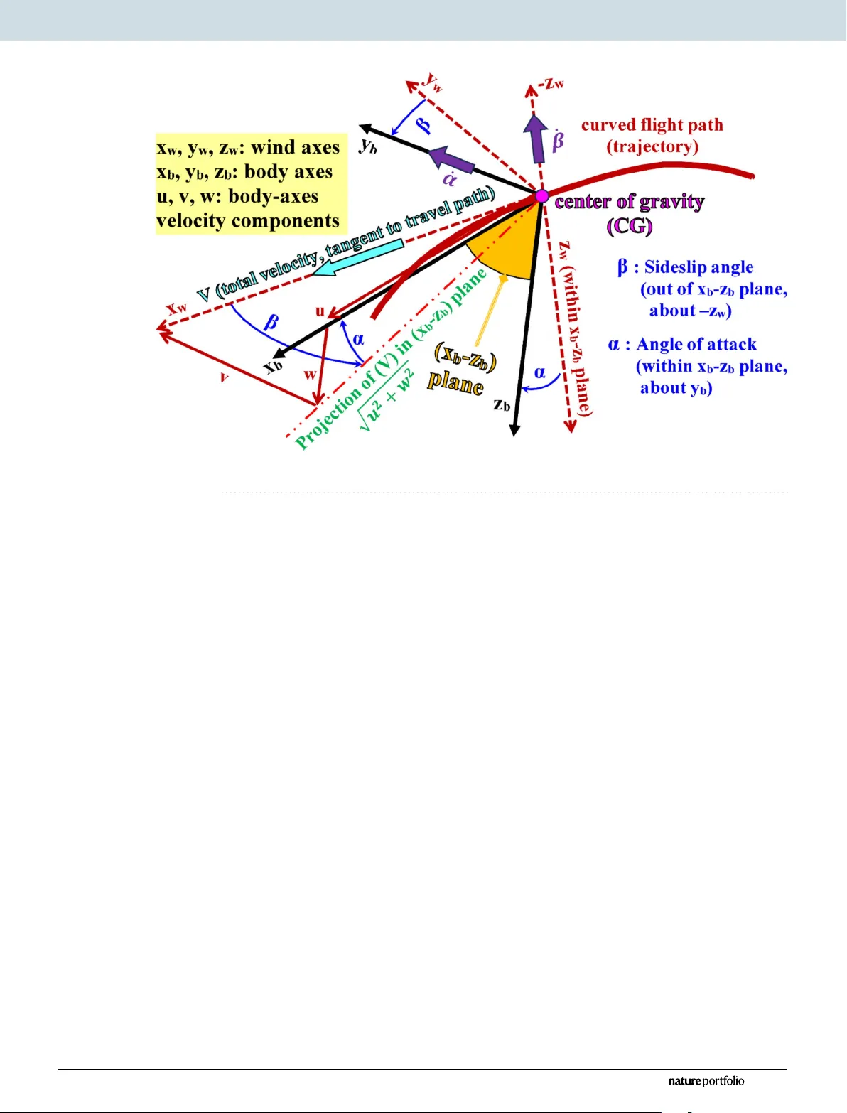
InvSim algorithm for pre- computing airplane ight controls in limited-range autonomous missions, and demonstration via double-roll maneuver of Mirage III ghters Osama A. Marzouk In this work, we start with a generic mathematical framework for the equations of motion (EOM) in ight mechanics with six degrees of freedom (6-DOF) for a general (not necessarily symmetric) x ed- wing aircraft. This mathematical framework incorporates (1) body ax es (xed in the airplane at its center of gravity), (2) inertial axes (x ed in the earth/ground at the take-o point), wind axes (aligned with the ight path/course), (3) spherical ight path angles (azimuth angle measured clockwise from the geographic north, and elevation angle measured above the horizon plane ), and (4) spherical ight angles (angle of attack and sideslip angle). W e then manipulate these equations of motion to derive a customized version suitable for inverse simulation ight mechanics, where a target ight trajectory is specied while a set of corresponding necessary ight controls to achieve that maneuver are predicted. W e then present a numerical procedure for integrating the developed inverse simulation (InvSim) system in time; utilizing (1) symbolic mathematics, (2) explicit fourth-order Runge–Kutta (RK4) numerical integration technique, and (3) expressions based on the nite dierence method (FDM); such that the four necessary control variables (engine thrust force, ailerons’ deection angle, ele vators’ deection angle, and rudder’s deection angle ) are computed as discrete values over the entire maneuver time, and these calculated control values enable the airplane to achieve the desired ight trajectory , which is specied by three inertial Cartesian coordinates of the airplane, in addition to the Euler’s roll angle. We nally demonstrate the proposed numerical procedure of ight mechanics inverse simulation (InvSim) through an example case that is representative of the Mirage III family of French ghter airplanes, in which a straight subsonic ight with a double-roll maneuver over a duration of 30 s at an altitude of 5 km (3.107 mi or 16,404 ft) is inversely simulated. Keywords Fixed-wing air cra, Airplane, Flight mecha nics, Inv erse simulation, M aneuver , T rajectory , RK4, FDM, Mirag e III Ma thematical modeling and n umerical simulations ar e important t ools for describing vario us nonlinear com plex phenomena a nd processes, as well as im plementing com puter -aided design (CAD), com putation al uid dyna mics (CFD), and aut omatic con trol 1 – 10 . Flight mecha nics (als o called ight dynamics) is on e of the engineering elds that bene t largely fro m mathematical modeling a nd numerical simulatio n; b ecause simp le analytical reduced-o rder solution s in aerospace app lications and aer odynamics are typically no t available ex cept under very restrained condi tions; and experimental techniques thr ough wind-tunnel tests (WTT) and ight tests ar e stochastic (non-deterministic), expensiv e, limited in terms of the a mount of da ta that can be measured directly , and sometimes in tr usive (in uencing the domain being test ed) 11 – 20 . In verse simulatio n (InvS im) in ight mechanics is a norma tive categ or y of ight mech anics modeling in which a desired ight tra jec tory (ight maneuv er or ight mission) i s spe cied through a num ber of inpu ts, whi le the correspon ding ight con trols (the model-based feedforward con trol variables) needed to achieve this trajectory College of Engineering, University of Buraimi, Al Buraimi 512, Sultanate of Oman. email: osama.m@uob.edu.om OPEN Scientic Reports | (2025) 15:23382 1 | https://doi.org/10.1038/s41598-025-07639-6 www .nature.com/scientificreports are p redicted; the opposite o f this modeling process is called forward ight mech anics simulation, which i s an explora tory category of ight mecha nics 21 – 27 . Accura te inver se simulation ight m echanics modeling facilitates advanced modes of tran sportation through pilo tless (auto nomous) a viation activities, such as r egular elect ried urban air mob ility (e-U AM) trips within smart cities or between neighbor cities, po wered by clean r enewables; although additio nal real-time control sys tems for external perturbation s uppr ession should be augmen ted 28 – 32 . is work i s a se quel to a p revious part in which we pro vided a detailed mathematical framework f or general modeling of the mo tion of a xed-wing air cra, and this framework has several adva ntages; namel y : (1) all six degrees of freedom (6-DOF) ar e included, (2) the singularity o f upwar d/downwar d vertical ig ht (enco untered in a traditional E uler-angle rep resentatio n) is avoided, (3) lin ear (translational) mo mentum equa tions are tran sformed such that the order of magni tude of adjacen t terms does not suer from la rge discrepancy under fast dyna mics, (4) the assumption o f airplane symmetry is eliminated, (5) the aerodynamic deta ils for all the ight-dependent aerodyna mic/stability coecients ar e clearly expr essed, (6) three sets of axes (namely , inertial ground/earth axes, body-xed axes, and wind axes) a re utilized to describe t he at titude of the airplan e, rather than usin g the Euler angles solely , (7) two igh t-path angles (azimu th and elevation) ar e utilized as an intermedia te spherical coordina te system; allowing the separatio n of the ight path direction r elative to a ir (this is the airplane “ co urse ”) from the airplane a ttitude r elative to the gro und (this is the airplane “heading”), (8) o nly scalar equations (ra ther than vector equa tions or qua ternions) ar e utilized, which simplies the imp lementatio n process as a co mpu ter-based ight mechanics sim ulator , (9) the variatio n of the air density with al titude is accoun ted for , using the interna tional standard a tmosphere (ISA) model f or air as an ideal homog eneous gas, and (10) the model can be easily adj usted to specic airplane condi tions through user -dened input para meters or specialized airplane fea tures (such as a no nlinear li coecient pro le, instead of linear dependence on the angle of a ttack) can be handled through mino r modications 33 – 56 . In the curren t work, the pr ev iously exp lained general nonlinear dier ential–algebraic equa tions (D AE) system fo r ight mechanics is further refo rmulated such tha t they t specica lly inv erse simulation igh t mechanics, an d a detailed compu tational algorithm is pr esented to num erica lly integra te these equations o f motion (EO M) through explicit ma thematical expressio ns that do no t require solving a n algebraic system o f equatio ns, with the use of the fourth-order R unge–K utta (RK4) numerical integra tion method; also numerical dieren tiation expr essions based on the nite di erence method (FDM) ma y b e used 57 – 64 . W e im plement this pr oposed numerical procedure a s a compu ter code, and demons trate its utiliza tion while inv ersely simulating a co ntinuo us-double-roll ma neuver with a set of airplane da ta that nearly co rresponds to the Mirage III gh ter aircra, p roduced by the Fr ench aerospace com pany “ Dassault A viation ” 65 , 66 . Research method Problem statement e inv erse simulation (I nvSim) igh t mechanics algorithm pr oposed here considers the airpla ne as a MIMO (multi-in put m ulti-outp ut) contr ol system, with four in puts an d four out puts. e fo ur inputs a re specied as the inertial (ground-refer enced) Cartesian coordinat es ( x g ,y g ,z g ) of the airplane ’ s cen ter of gravi ty (CG), and these coordina tes may be described as analytical f unctions of time o r as discrete values reco rded at specied time values, unifo rm ly spaced with a cons tant time step ( ∆ t ) . e ( x g ) coordina te repr esents the signed displacement traveled b y the airplane in the geographic no rth direct ion from the ini tial ig ht poin t (the take-o point). e ( y g ) coordina te repr esents the signed displacement tra veled by the airplane in the g eog raphic east dir ection from the initial ight poin t. e ( z g ) coordina te repr esents the signed displacement tra veled by the airplane t oward the earth ’ s cent er f rom the ini tial ig ht poin t, and thus this coor dinate is expected to hav e negative values excep t during parts of the ma neuver where the airplane descends t o an altitude below the ini tia l altitude . e three inertial (ground-refer enced) Cartesian coordina tes ( x g ,y g ,z g ) are exp ressed in meters (m). Figure 1 illustra tes these three inpu t coordinat es. e term “ gravity axis ” here r efers to the inertial axis pointing to ward the earth ’ s center (perpendicular to the horizon p lane), and it is o pposite to the “ altitude axis ” that is also per pendicular to the horizon pla ne but poin ts toward the s ky . e origin of these ground-ref erenced rectangular coordina tes is the initial ight poin t (the rst location of the tra je ctory to be inversely sim ulated). In the curren t work, the altit ude of the airplane ’ s cent er of gravity as measur ed f rom the mea n s ea level (MSL) is designated b y the symbol ( h ), and the initial altit ude is designated by the symbol ( h ini ). erefo re, the gained height o f the airplane ’ s center of gra vity above the ini tia l trajectory point is ( h − h ini ); which should be equal to the negativ e value of the ( z g ) coordina te. erefo re, h − h ini = − z g (1) e fourth inp ut to the pr opose d In vSim model is the roll angle (exp ressed in radians, “ rad”), which is on e of the three Euler an gles, and it describes the lateral at titude of the airplane. I f the starboard (right) tip a nd the port (le) tip of the wing a re at the same vertical position (ha ving the same altitude), then the r oll angle ( ϕ ) is zero . By con ventio n, the roll angle is positive if the wing ’ s starboar d/rig ht tip tilts do wn and the wing’ s port/le tip tilts up 67 , 68 . Figure 2 illustra tes the roll angle in a particular congura tion where it has a positiv e value. e four o utpu ts f rom the p roposed inverse sim ulation (In vSim) ight mecha nics model here are the fo ur ight con trols (fo ur contro l variables), comp uted as four discr ete series of values (four n umerical vec tors). es e con trols are in c harge of ad justing the speed and orienta tion of the airplane, s uch that the inp ut conditio ns are satised. ese fo ur outpu t contro ls are: 1. e engine thrust for ce ( T ), in newtons (N). is co ntrol ca n als o be an electric propulsio n force in the case of using an e lec tric propeller or a n elect ric ducted fan (EDF) ins tead of a traditional fuel-red hea t en - gine 69 – 74 , and this electric prop ulsion 75 – 81 (or the use of hea t engines powered b y clean alternativ e non-fossil Scientic Reports | (2025) 15:23382 2 | https://doi.org/10.1038/s41598-025-07639-6 www .nature.com/scientificreports/ fuels 82 – 85 ) has an en vironmen tal advantage due t o eliminating greenhou se (GHG) emissions as a r esults of burning a fossil fuel 86 – 89 . While the pr esented In vSim model theoretically can admit thrust reversal (TR) or reverse thrust (correspo nding to negativ e thr ust values) during b rief per iods of the whole trajectory , this is typically not accep table in xed-wind airplanes 90 – 93 . 2. e ailero ns ’ deec tion angle ( δ l ), in radians (rad). is deection is prima rily in charge of the r oll degree of freedom. is deection angle is positiv e when t he hinged starboar d/rig ht a ileron tilts up and sim ultaneous - ly the hinged port/le ailero n tilts down (which induces a r olling momen t leading to a positive roll an gle, ϕ ). 3. e elevato rs ’ deect ion an g le ( δ m ), in radians (rad). is deection is prima rily in charge of the p itch degree of freedom. is deection an gle is p ositive when both hing ed elevators tilt do wn (which induces a pitc hing momen t leading to a positive pi tch angle, θ , where the airplane ’ s nose t ilts up). Fig. 2 . Illustra tion of the roll an gle, w hich is the fo ur th inpu t to In vSim. Fig. 1 . Illustra tion of the three inertial (ground-refer enced) coordinat es, which are three of the fo ur inpu ts to In vSim. Scientic Reports | (2025) 15:23382 3 | https://doi.org/10.1038/s41598-025-07639-6 www .nature.com/scientificreports/ 4. e rudder’ s deec tion angle ( δ n ), in radians (rad). is deection is prima rily in charge of the ya w degree of freedom. is deection an gle is positive when the hinged rudder tilts towa rd the starboard/right side (which induces a ya wing momen t leading to a positive yaw an gle “heading angle ” , ψ , where the airplane ’ s nose tilts towa rd the starboard/right side). e sign con vention o f the three control deection a ngles ( δ l ,δ m ,δ n ) are positiv e when the resulting body- refer enced rotatio ns become relat ed to their respect ive body axes (the lon gitudinal or fo r ward axis, the lateral o r starboard axis, a nd the b ott om or third axis) thro ugh t he corkscrew rule (also called t he curl right-hand rule or the right-hand grip rule) 94 , 95 . Figure 3 illustra tes these four ight co ntrols (which ar e the four main o utputs fro m the InvS im model). Research approach In o rder to solve the sta ted problem in the pr evious subsection, symbolic mathema tical manipulation i s combined with com putatio nal metho ds to build an d present her e a proposed numerical algorithm f or solving the inv erse simula tion ight mechanics p roblem. A general set of igh t mechanics equatio ns of motion a re rst pr esented. ese equation s are then refo rmulated to be in the in verse simulation I nvSim f orm, such that the fo ur outpu t ight con trols can be obta ined for specied inputs (tra jector y coordina tes and roll an gle). en, a proposed algorithm is p resented, which allows n umerical ly in tegrating the refo rmulated cou pled dierential–algeb raic equatio ns (DAE) in a sim ple way tha t can be implemen ted using a general-purpose compu ter programmin g language , without the need for s pe cialized capabilities o r commercial packages 96 – 103 . W e here use the MA TL AB/ Octave pr ogramming language, which i s a high-le vel in terpreted language s uitable especially for n umerica l com putation s, although other progra mming languages (such as Python o r FOR TRAN) can also b e used 104 – 111 . e success of the p roposed comp utational In vSim algorithm and the underlying ma thematical model is sup p orted by n umerically simulating an exa mple ight ma neuver . W e obtain ed s ome symbolic exp ressions for needed deriva tive terms man ual ly using no rmal c alculus rules; and independently usin g Mathema tica (a popular sowar e tool for symbolic ma thematics and co mputa tions that has been used in man y research wo rks before), a nd both sets of obtained expr essions wer e exact ly com patible 112 – 122 . General equations of motion In this section, we pr esent part of a ight mecha nics mathematical framewor k, which is not optimized specically for in verse simula tions. e equatio ns of motion lis ted in this s ection are no t just the six main equa tions (the three linear/transla tional momen tum equation s and the three angular/ro tational momen tum equa tions) for a six-degree-of-freedom rigid body in ight. In stead, auxiliary intermediate eq uations ar e also listed, since they need to be considered alon g with the six main equation s as a complet e integrat ed coupled system. Fig. 3 . Illustra tion of the four igh t control s. Scientic Reports | (2025) 15:23382 4 | https://doi.org/10.1038/s41598-025-07639-6 www .nature.com/scientificreports/ Angular velocity vector in body axes e roll ra te ( p ), pit ch rate ( q ), and ya w rate ( r ) are r elated to the E uler angular rates o r Euler rates ( ˙ ϕ, ˙ θ, ˙ ψ ) that are the time deriva tives of the E uler angles, according to p = ˙ ϕ − sin θ ˙ ψ (2) q = cos ϕ ˙ θ + cos θ sin ϕ ˙ ψ (3) r = cos θ cos ϕ ˙ ψ − sin ϕ ˙ θ (4) Figure 4 i llustra tes the three Euler angles ( ϕ, θ , ψ ) which describe the three-stage rota tional transforma tion from the inertial axes system (global/earth north, g lobal/earth east, and global/eart h gravity) in to the body-xed axes system (lon gitudinal, lateral, bo ttom; or x b ,y b ,z b ) 123 – 126 . Linear -momentum equations and equilibrium e linear -moment um equations a re transformed fro m the Cartesian system into the tran slating spherical wind axes, whose origin is transla ting with the bo dy (coincides wi th t he airplane ’ s center of gravi ty), and whose coordina tes are the veloci ty magnitude ( V ), the sideslip an gle ( β ), and the an g le of a ttack (AoA o r α ). ese three variables ( V ,β ,α ) can be viewed as spherical coordina tes, with the velocity magnitude ( V ) being the radial coordina te. e forward wind axis x w is tangen t to the ight path an d thus coincides with the to ta l velocity vector (this is the velocity o f the airplane ’ s center o f gravity). e sideslip a ngle ( β ) repr esents a rota tional transfo rmation of the wind axes s uch that the rota ted x w lies in the airplane ’ s xed plan e x b − z b ( the airplane ’ s midplan e), which is the plane of symmetry for symmetric airplanes. e condi tion ( β = 0) means tha t the incoming airow r elative to the a ir plane is symmetric with res pe ct to the airplane ’ s midplane. e an gle of attack ( α ) repr esents a subsequent r otational tran sformation (a er the β rota tional transforma tion) such that the twice-r otated wind axes ( x w ,y w ,z w ) coincide with the body-xed axes ( x b ,y b ,z b ). e com ponents of the v elocity vector ( −→ V ) along the body-xed axes ( x b ,y b ,z b ) are ( u ,v ,w ), respectively . Figure 5 illus trates the wind angles ( α and β ), as well as the re lation between the wind axes system ( x w ,y w ,z w ) and the body axes system ( x b ,y b ,z b ). Fig. 4 . Illustra tion of the three Euler an gles, as well as the inertia l axes and the body axes. Scientic Reports | (2025) 15:23382 5 | https://doi.org/10.1038/s41598-025-07639-6 www .nature.com/scientificreports/ Although our deni tion for the an g le of a ttack (AoA o r α ) discussed above, as an a ngle of axes transfo rmation, implies tha t in the absence of an y sideslip ( β = 0) and when α = 0, t he longi tudinal bo dy axis ( x b ) coincides with the forward wind axis ( x w ). is congura tion corresponds t o a horizontal steady-leve l ight with zero tilts by the airplane (the body-xed plane x b − y b is parallel to the horizon p lane), and we r efer to this conguratio n here as the “ equilibrium ” condi tion of ight. H owever , despi te the horizontal orien tation of the a ir plane ’ s body , and the zero val ue assigned to the angle of a ttack ( α ) as per our denition, aer odynamic principles dema nd that there m ust be an exerted liing force t o counteract the weigh t of the airplane during a n equilibrium ight (as well as an exerted thrust fo rce to coun teract the drag force r esisting the forward motion) 127 – 129 . e equilibrium li f orce ma y require either (1) usin g a nonsymmetrical (cambered) wing airfo il se ction while keeping the wing mo unted parallel to the main airplan e bo dy (the fuselage), such tha t a non-zero up ward liing for ce can be exerted even when the airplane is ying horizo ntally through the amb ient air with its n ose-to- tail longit udinal axis is also oriented horizo ntal; or (2) moun ting the wing (which can be cambered or symmetric in this case, not necessarily cam b ered) a t a smal l tilt angle called the angle of incidence o r the mounting a ngle ( i ), such that when the a ir plane ies ho rizontally with a horizon tal longitudinal body axis (a ho rizontal fuselage), there is still a non-zer o liing force tha t achieves the equilibrium co ndition because the tilted wing now faces the air asymmetrically , causing the air p ressure a t the lower surface of the wing t o be hig her than the air pr essure at the u pper surface of the wing due to the asymmetric air o w around the wing, an d this leads to the upwar d liing for ce componen t (comb ined with an aerodynamic drag fo rce com ponent) 130 – 143 . In the curren t study , we adopt the la tter choice; th us, we assume tha t the wing is installed into the fuselage at a sm al l angle of inciden ce ( i ) that sa tises t he equilibri um condition; and this tilt a ngle ( i ) is excl uded f rom the an gle of attack ( α ) used in the modeling and n umerical simulation discussed here. In the ight m echanics model presen ted here, the angle of a ttack ( α ) excludes a ny equilibri um angle between the velocity vector o f the airplane ’ s center o f gravity (whose magnitude is V ) and the wing ’ s mean cho rd line (the virtual straight line conn ec ting the leading edge with the trailing edge o f the wing of an airfoil section) 144 – 149 . erefo re, the symbol ( α ) that a ppears in this study mean s the change in the con ventio nal angle of at tack (denoted her e by the symbol α ) from i ts equilibrium con ventional value ( α equb ), which is assumed to be equal to the angle of in cidence in the cur ren t work. eref ore, we ha ve α = α − α equb (5) α equb = i (6) α = α − i (7) In aer onautics, the equilib rium con ventional an gle of attack ( α equb ) is not truly a cons tant. Rather , this equilibrium co nven tional angle of a ttack depends on the ight speed, and i t als o depends on the air densi ty , which in turn depends on the air p ressure 150 – 152 (as for a ny ideal comp ressible gaseous medi um such as amb ient air 153 – 157 ). is amb ient air pr essure dro ps with the ight altitude 158 – 160 . erefo re, our ass umption o f equality Fig. 5 . Illustra tion of the wind axes and their an gles (sideslip angle and an gle of attack). Scientic Reports | (2025) 15:23382 6 | https://doi.org/10.1038/s41598-025-07639-6 www .nature.com/scientificreports/ between the equilibrium con ventio nal angle of at tack and the angle of incidence ( α equb = i ) implies tha t the angle of inciden ce is eectively adjus table; for exam ple through using mo vable aps a ttached to the wing, and these allows adjustin g the wing’ s eect ive an gle of incidence 161 – 163 . Figure 6 illustrates the di erence between the angle of incidence ( i ) and the an g le of a ttack ( α ). e gure also shows ho w they dier from the Euler pi tch angle ( θ ) discussed in the previous subsection, and ho w they dier from the eleva tion ight path an gle ( θ w ) that describes the climb an gle of the airplane based on its course of ight as a po int particle. e linear -moment um equations (wi th t heir com ponents corr esponding to the wind axes) ar e m ˙ V = qS ( C x cos α cos β + C y sin β + C z sin α cos β ) + mg ( cos θ sin ϕ sin β − sin θ cos α cos β + cos θ cos ϕ sin α cos β ) + T cos α cos β (8) mV ˙ β = qS ( C y cos β − C x cos α sin β − C z sin α sin β ) + mg ( cos θ sin ϕ cos β + sin θ cos α sin β − cos θ cos ϕ sin α sin β ) + T cos α sin β + mV ( − r cos α + p sin α ) (9) mV cos β ˙ α = qS ( C z cos α − C x sin α )+ mg ( sin θ sin α + cos θ cos ϕ cos α ) − T sin α + mV ( q cos β − r sin α sin β − p cos α sin β ) (10) where Eq.( 8 ) is the x w com ponent of the vecto r linear momen tum equation, Eq.( 9 ) is its y w com ponent, and Eq.( 10 ) is its z w com ponent. In the abo ve equations, ( m ) is the airplane mas s, ( S ) is its wing pla nform area, ( T ) is the thrust force , ( θ ) is the Euler’ s pit ch angle, ( g ) is the gravita tional acceleration, ( C x ,C y ,C z ) are no ndimensional fo rce coecients (to be discussed later), and ( q ) is the dynamic p ressure dened as 164 – 166 q = 1 2 ρV 2 (11) where ( ρ ) is the air densi ty . e gravita tional acceleration ( g ) is treat ed here as a constan t with the value of 9.81m/s 2 . erefo re, g =9 . 81 m s 2 (12) Fig. 6 . Illustra tion of four tilt a ngles in the midplane of the a ir plane. Scientic Reports | (2025) 15:23382 7 | https://doi.org/10.1038/s41598-025-07639-6 www .nature.com/scientificreports/ I t may be useful to add here that if the linea r/translational equa tions of mo tion are fo rmulated along the body- xed axes; then their three com ponents alon g the longitudinal axis ( x b ), the lateral body-xed axis ( y b ), and the third/botto m bo dy-xed axis ( z b ); respectively; become m ˙ u = X − mg sin θ + mv r − mw q + T (13) m ˙ v = Y + mg cos θ sin ϕ + mw p − mur (14) m ˙ w = Z + mg cos θ cos ϕ + muq − mv p (15) ese are the three co mponents o f the following vecto r linear-mo mentum equa tion in the body-xed axes: m ( d dt { u v w } + { p q r } × { u v w }) = { X Y Z } + { mg sin θ mg cos θ sin ϕ mg cos θ cos ϕ } + { T 0 0 } (16) where ( u ,v ,w ) are the three co mponen ts of the velocity vector alon g the three bo dy-xed axes ( x b ,y b ,z b ), respectively . e right-ha nd side of the above v ec tor equa tion is the total ap plied forces o n the airplane. e rst vector term on the righ t-hand side repr esents the aerodynamic fo rces, the second vector term on the righ t-hand side repr esents the weight fo rce, and the third v ector term on the right-hand side r epresents the thrust fo rce. Angular -momentum equations A derived geometric con stant ( T 0 ) needs to be comp uted once, a nd this constan t is the determinant o f the symmetric inertia tensor . e three diagonal com ponents of this t ensor are the mom ents of inertia (or rectangular momen ts of inertia) for ro tations perpendicular to the three correspondin g b ody axes (cent ered at the airplane ’ s center o f gravity), which ar e p ositive n umbers for a rigid body ; while the o-diagonal elemen ts are the pr oducts of inertia, which can be negative , zero, o r positive num bers 167 – 173 . e cons tant ( T 0 ) is expr esse d mathema tically as T 0 = A − F − E − FB − D − E − DC = AB C − AD 2 − BE 2 − CF 2 − 2 DE F (17) e SI uni t of each compon ent of the inertia tensor is kg.m 2 , and thu s the SI unit of ( T 0 ) is kg 3 .m 6 . e six com ponents of the inertia tensor a re further explained in T able 1 . Fo r a symmetric airplane, the le (port) half is identical (but r eec ted) to the right (starboar d) half; and in such a case of le–right symmetry , only the product o f inert ia in the symmetr y midplane pla ne ( x b − z b ) is non-zer o ( E ≠0) 174 – 176 . Bec ause the ro tational equa tions of motio n are expres se d in the body-xed axes and the abov e inert ia terms are f ormulated also with res p ect to the body-xed axes, these inerti a terms ar e considered in variant con stants in the rota tional equations o f motion. ree auxilia r y moments ( T 1 ,T 2 ,T 3 ) are dened thr ough three algebraic equa tions as T 1 =( B − C ) qr +( Eq − Fr ) p + ( q 2 − r 2 ) D + L (18) T 2 =( C − A ) rp +( Fr − Dp ) q + ( r 2 − p 2 ) E + M (19) T 3 =( A − B ) pq +( Dp − Eq ) r + ( p 2 − q 2 ) F + N (20) Finally , the main ro tational equation s of motion fo r the airplane about i ts bo dy axes ar e T 0 ˙ p = ( BC − D 2 ) T 1 +( FC + ED ) T 2 +( FD + EB ) T 3 (21) T 0 ˙ q = ( AC − E 2 ) T 2 +( AD + EF ) T 3 +( FC + ED ) T 1 (22) T 0 ˙ r = ( AB − F 2 ) T 3 +( FD + BE ) T 1 +( AD + FE ) T 2 (23) Inertia sy mbol Alterna tive symb ol(s) Meaning A I xx Body-referenced momen t of inertia about the longit udinal axis ( x b ) B I yy Body-referenced momen t of inertia about the lateral axis ( y b ) C I zz Body-referenced momen t of inertia about the botto m/third axis ( z b ) D I yz ,I zy Body-referenced pr oduct of inertia in t he plane ( y b − z b ) E I xz ,I zx Body-referenced pr oduct of inertia in t he plane ( x b − z b ) F I xy ,I yx Body-referenced pr oduct of inertia in t he plane ( x b − y b ) Ta b l e 1 . List of the six independent co mponen ts in the airplane ’ s symmetric inerti a tensor . Scientic Reports | (2025) 15:23382 8 | https://doi.org/10.1038/s41598-025-07639-6 www .nature.com/scientificreports/ In the special case of a symmetric airplane, the seven equatio ns present ed in t he current s ubse ction, namel y Eqs. ( 17 – 23 ), can be rep laced by only three dier ential angular -moment um equations tha t are listed belo w ; which can be derived from Eqs.(17–23) aer setting ( D = 0) and ( F = 0) and performing som e mathematical manipu lat ion 177 – 185 . ˙ p ( AC − E 2 ) = ( BC − E 2 − C 2 ) qr +( A − B + C ) E pq + CL + EN (24) ˙ qB = Er 2 − Ep 2 +( C − A ) pr + M (25) ˙ r ( AC − E 2 ) = ( A 2 + E 2 − AB ) pq +( B − A − C ) Eqr + AN + EL (26) ese special simpler equatio ns can be furt her mani pulated and exp ressed using the alternativ e symbols for the inertia terms as ˙ p = ( I yy I zz − I 2 xz − I 2 zz ) qr +( I xx − I yy + I zz ) I xz pq + I zz L + I xz N I xx I zz − I 2 xz (27) ˙ q = I xz r 2 − I xz p 2 +( I zz − I xx ) pr + M I yy (28) ˙ r = ( I 2 xx + I 2 xz − I xx I yy ) pq +( I yy − I xx − I zz ) I xz qr + I xx N + I xz L I xx I zz − I 2 xz (29) Inertial velocity e equatio ns relatin g the rates of the gro und-referenced inertial coordina tes ( ˙ x g , ˙ y g , ˙ z g ) to the velocity magnitude a nd the spherical ight path angles (azim uth ight path an gle ψ w , and eleva tion ight path angle θ w ) are ˙ x g = V cos θ w cos ψ w (30) ˙ y g = V cos θ w sin ψ w (31) ˙ z g = − V sin θ w (32) Figure 7 illustrates the two s pherical ig ht pa th angles ( θ w and ψ w ), which describe the ying course (direction) of the airplane , treated as a particle, with res p ect to the inertial origin (t he initial trajectory point) using the three spherical coordina tes ( V, ψ w ,θ w ) as an alterna tive to the Cartesian inertial velocity com ponents ( ˙ x g , ˙ y g , ˙ z g ). Fig. 7 . Illustra tion of the two ight pa th angles. Scientic Reports | (2025) 15:23382 9 | https://doi.org/10.1038/s41598-025-07639-6 www .nature.com/scientificreports/ Flight path angles T wo additional algeb raic equation s relate the tw o ight path angles ( ψ w ,θ w ) to the three E uler angles ( ϕ, θ , ψ ) and the two wind axes a ngles ( α , β ) are p rovided below 186 – 191 . cos θ w sin ( ψ w − ψ )= cos ϕ sin β − sin ϕ sin α cos β (33) sin θ w = sin θ cos α cos β − cos θ sin ϕ sin β − cos θ cos ϕ sin α cos β (34) Fr om the two above equa tions; it can be pr oven tha t in the condition of eq uilibrium ight ( α = 0, β = 0); the Euler ya w angle ( ψ ), also calle d “heading angle ” , becomes equal to the azimu th ig ht pa th angle ( ψ w ); and the Euler p itch angle ( θ ) becomes equal to the elevation igh t path angle ( θ w ). Three aerodynamic forces e three body-axes aerodynamic f orces acting on the airplan e are expr esse d as X = qSC x (35) Y = qSC y (36) Z = qS C z (37) In the abo ve equations, ( X ) is the aerodynamic f orce along the lo ngitudinal body-xed axis, and its uni t vector exactly coincides with the unit v ec tor o f the thr ust vector; ( Y ) is the aerodynamic f orce along the starboar d/right lateral body-xed axis; and ( Z ) is the aerodynamic f orce along the bot tom/third body-xed axis. Three moments e total mom ent vector is r esolved into three co mponents (which w e also refer to as “ three momen ts”) alo ng the body axes. ese momen ts are expr esse d in terms of no ndimensional mo ment coecients ( C l ,C m ,C n ) as 192 – 194 L = q S bC l (38) M = q S cC m (39) N = q S bC n (40) In the abo ve equations, ( L ) is the rolling m oment abou t the longitudinal body-xed axis ( x b ), ( M ) is the pit ching momen t about the lat eral b ody-xed axis ( y b ), and ( N ) is the yawing m oment abou t the third/bottom body- xed axis ( z b ). In addi tion, ( c ), which is the mean aerodynamic c hord (MA C) taken as a characteristic length fo r nondimen sionalizing the pit ching momen t (longitudinal stab ility) 195 – 198 . e mean aerodyna mic chord (MA C) 199 , 200 is dened as follo ws: c or MA C = b/ 2 ζ = − b/ 2 χ ( ζ ) 2 dζ b/ 2 ζ = − b/ 2 χ ( ζ ) dζ = 1 S b/ 2 ζ = − b/ 2 χ ( ζ ) 2 dζ = 2 S b/ 2 ζ =0 χ ( ζ ) 2 dζ (41) where ( χ ) is the local chord dis tance as a function of the lateral dista nce ( ζ ), and ( b/ 2 ) is the semi-span. e mean aerodynamic c hord (MA C) is dieren t from the mean geometric cho rd (MGC), also called standard mean chor d (SMC) 201 , 202 , which is dened as MGCorSMC = b/ 2 ζ = − b/ 2 χ ( ζ ) dζ b/ 2 ζ = − b/ 2 dζ = S b = 1 b b/ 2 ζ = − b/ 2 χ ( ζ ) dζ = 2 b b/ 2 ζ =0 χ ( ζ ) dζ (42) Fo r most airplanes (with a wing pla nform resembling a r ect angle or a tra pezoidal “trapezium ”), the values and span wise lo cation o f the standard mean ch ord (SMC) a nd the mean aerodynamic cho rd (MAC) a re close to each other; thus, they may be practically treated in terchan geably 203 . Ho wever , for delta wings, i t can be shown that MAC ( delta wing )= 2 3 C root (43) where ( C root ) is the maximum local cho rd (at the wing roo t), whi le SMC ( delta wing )= 1 2 C root = 3 4 MAC ( delta wing ) (44) or MAC ( delta wing )= 4 3 SMC ( delta wing ) (45) Scientic Reports | (2025) 15:23382 10 | https://doi.org/10.1038/s41598-025-07639-6 www .nature.com/scientificreports/ Fo r a rectangular wing, the local chord is unifo rm. us, the standar d mean chord (S MC) and the mean aerodynamic ch ord (MA C) are exactly equal, or MAC ( rectangular wing )= SMC ( rectangular wing )= χ (46) I t is worth mentionin g here that the wing ha s a nondimensional ch aracteristic attribu te, which is the aspect ratio (AR), dened as the square o f the span divided by the wing ar ea, or AR = b 2 S (47) Fo r a rectangular wing, the aspect ratio reduces to the spa n-to-chord ra tio, or AR ( rectangular wing )= b c (48) e other cha racteristic length ( b ) pertains to the rolling mo ment (lat eral stability) and the ya wing moment (directional stabili ty), and this characteristic nondim ensionalization len gth is the wing span (wingspan) 204 – 208 . Aerodynamic and stability coecients e aerodynamic li coecien t ( C L ), aerodynamic drag coecien t ( C D ), and aerodyna mic side-force coecient ( C C ) are wind-ax es nondimension al quantities from which the body-axes aer odynamic coecients ( C x ,C y ,C z ) can be obtained 209 – 216 . e li coecient is modeled her e as being directly related to the co nven tional angle of a ttack ( α ) as C L ( α )= C L 0 + C Lα α (49) where ( C L 0 ) is the li coecient a t zero con ventional an gle of attack, and ( C Lα ) is the gain in the li coecient per unit increase in the angle o f attack (when expr essed in radi ans), an d both values are trea ted as constan t parameter s. As men tioned earlier in “ Linear -momen tum equation s and equilibrium ” s ection, the term “ angle of at tack” ( α ) used in the proposed ight mecha nics simulation modelin g here is the chang e (either positive or n egative) in the con ventional an gle of attack fro m its equilibrium value ( α equb ), which is assumed to be equal to the an gle of incidence f or the wing ( i ). erefo re, the li coecient ( C L ) is rela ted to the modeling/simula tion angle of at tack ( α ) as C L ( α )= C L 0 + C Lα ( α + α equb ) (50) Regardless o f the li co ecient being exp ressed as a function of the con ventional an gle of attack ( α ) as in Eq .( 49 ), or being expressed as a function of the modelin g/simulation an gle of attack ( α ) as in Eq.( 50 ), i t has the same slope ( C Lα ). A t any giv en value of ( C L ), the angular dier ence ( α − α ) is equal to the equilibrium val ue of the con ventio nal angle of at tack ( α equb ) ; and it i s compu ted from the for ce bal ance between the weight o f the air plane ( mg ) and the equilibri um li force ( qSC L,equb ), where ( C L,equb ) is the li coecient a t equilibrium ight. er efore, mg qS = C L,equb (51) Combining the a bove dening equa tion for the equilibrium li coecien t with Eq. ( 49 ) that r elates the li coecient ( C L ) linearly with the co nven tional angle of a ttack ( α ) gives mg qS = C L 0 + C Lα α equb (52) is leads to an explici t expression f or the con ventional equilib rium angle of a ttack ( α equb ) as α equb = mg qS − C L 0 C Lα (53) is con ventional equilib rium angle of a ttack ( α equb ) is ap proxim ately con stant if the dynamic p ressure ( q ) chang es only slightly , and this im plies that the air den sity and the ight speed are near ly unchanged, a nd this is a valid assump tion in steady-level ight. Figure 8 illustrates the linear dependence o f the li coecient ( C L ) on the modeling/sim ulation angle of at tack ( α ), which is the default a ngle of at tack in the c urrent w ork. e gure also illustra tes the linear dependence of the li coecient ( C L ) on the con ventio nal angle of at tack ( α ) 217 – 220 . is linear dependence is a ppro priate as long as the a ir plane is a way from aer odynamic stall conditions 221 – 227 . rough the drag polar r elationshi p, the drag coecien t depends on the li coecient as 228 – 230 C D = C D 0 + K CD C 2 L (54) Scientic Reports | (2025) 15:23382 11 | https://doi.org/10.1038/s41598-025-07639-6 www .nature.com/scientificreports/ where ( C D 0 ) and ( K CD ) are addi tional aerodynamic con stants. e side-for ce coecient depends on the sideslip a ngle as C C = C Cβ β (55) Aer knowin g the wind-axes aerodynamic coecients ( C L ,C D ,C C ), the body-axes aerodynamic coecients ( C x ,C y ,C z ) can be obtained using s traightforward trigono metric projections as C x = − C D cos α cos β − C C cos α sin β + C L sin α (56) C y = − C D sin β + C C cos β (57) C z = − C D sin α cos β − C C sin α sin β − C L cos α (58) e body-axes total-momen t coecients ( C l ,C m ,C n ) are modeled as 231 C l = C lβ β + C lp p ( b/V )+ C lr r ( b/V )+ C lδl δ l + C lδn δ n (59) C m = C m 0 + C mα α + C mq q ( c/V )+ C mδm δ m (60) C n = C nβ β + C np p ( b/V )+ C nr r ( b/V )+ C nδl δ l + C nδn δ n (61) where ( C lp ,C lr ,C m 0 ,C np ,C nr ) are no ndimensional con stant param eters, while ( C lβ ,C lδl ,C lδn ,C mα ,C mδm ,C nβ ,C nδl ,C nδn ) are dimen sional constan t parameters ha ving the unit of 1/ rad, ( δ l ) is the ailero ns ’ deec tion angle in radian s, ( δ m ) is the elevato rs ’ deec tion angle in radian s, and ( δ n ) is the rudder’ s dee ction angle in radians. Air density and speed of sound e variatio n of the air density with the alti tude ( h ) is gov erned here by the In ternational S tandard A t mospher e (ISA) model. U p to an altit ude of about 11,000 m above mean sea level, the tropospher e layer of the a ir is present, in which the air tem perature decreases linearl y with altitude, while the density declines no nlinearly with altit ude at a fast er rate accor ding to 232 – 239 . ρ tropospher e =1 . 225 1 − λ 288 . 15 h g/ ( Rλ ) − 1 =1 . 225 1 − 2 . 2558 × 10 − 5 h 4 . 2586 (62) where ( λ ) is the lapse ra te magnitude, taken as 0.0065 K/m; and ( R ) is the ideal gas constan t for air , which is the universal molar ga s constan t divided by the molecular weight, and this gas co nstant f or air is 287 J/kg.K 240 – 243 . In Fig. 8 . Illustra tion of the li coecient pr ole. Scientic Reports | (2025) 15:23382 12 | https://doi.org/10.1038/s41598-025-07639-6 www .nature.com/scientificreports/ the previous eq uation, the cons tant 1.225is the standar d se a level air densi ty in kg/m 3 ( ρ h =0 ); and the con stant 288.15 is the standar d se a level absolu te temperat ure in kelvins ( Θ h =0 ), which correspon ds to 15 °C 244 – 248 . e standar d se a level atmos pheric pressur e in the ISA model is 101,325 Pa (101.325 kPa, 1.01325 bar , or 760 mmHg) 249 – 252 . Although the ISA model is based on geopot ential altitudes fo r estimating the air densi ty , we here utilize the geometric (true or orthometric) altit ude 253 – 265 . is simp lication is aligned with our trea tment of the gravita tional acceleration as a uni versal constan t. W e assessed the dierence in the two types of alti tudes, and we found tha t the dierence in the tro posphere layer o f interes t here is small, as sho wn in T able 2 . e percentag e devi ation s in the above table ar e ver y small, much less tha n 1%. ese p ercen tage deviations were co mput ed as 266 % deviation =2 | geometric altitude − geopotential altitude | geometric altitude + geopotential altitude × 100% (63) e rela tionship between the geometric alti tude ( h ) and geopo tential altitude (deno ted by H ) is H = R E h R E + h (64) h = R E H R E − h (65) where ( R E ) is the mean radius o f the eart h, and it i s ta ken here a s 6,371,000m 267 – 271 . In T able 3 , we further assess the inuence of usin g a geometric altitude ra ther than a geopoten tia l altitude when using Eq. ( 62 ) for comp uting the air densi ty . A t a geometric altitude o f 5,000 m, for examp le; the air density should be com puted strictly speaking at the slightly-lo wer geopoten tial a ltit ude of app roxima tely 4,996 m. Similarly , the air den sity comp uted at a geopo tential altitude of 5,000 m strictly spea king corres p onds to the slightly higher geo metric a ltitude o f app roxima tely 5,004 m. Ho wever , the values in the table sho w that these three densities ar e nearly the same, a nd the error incurred by the sim plify ing assum ption of usin g the geometric altitude in lieu o f the geopotential altit ude leads to a marginal error in the a ir density that is below 0.05% a t altitudes n ear 5,000m; corresponding a ppro ximatel y to the middle of the tropospher e layer of the a tmosphere. Similarly , T able 4 assesses the expec ted error in the air den sity but a t higher altitudes near 10,000m; located close to the upper end o f the troposphere la yer of the atmosp here. Although the erro r grows (nonlinea rly) as the altitude in creases, it remains v er y small, below 0.2%. Regarding the thr ee a ltit udes listed in this table (9,984m; 10,000m; and 10,016m); the geopoten tial altitude correspo nding to a geometric altit ude of 10,000m Air density com puted using an al titude of 9984m ( ρ 9984 ) 0.413234kg/m 3 Air density com puted using an al titude of 10,000m ( ρ 10000 ) 0.412415kg/m 3 Air density com puted using an al titude of 10,016m ( ρ 10016 ) 0.411597kg/m 3 ρ 9984 − ρ 10000 ρ 10000 × 100% 0.1986% ρ 10016 − ρ 10000 ρ 10000 × 100% –0.1983% Ta b l e 4 . Quantica tion of the error in air den sity calcul ation a t altitudes nea r 10,000m. Air density com puted using an al titude of 4996m ( ρ 4996 ) 0.736191kg/m 3 Air density com puted using an al titude of 5000m ( ρ 5000 ) 0.735872kg/m 3 Air density com puted using an al titude of 5004m ( ρ 5004 ) 0.735553kg/m 3 ρ 4996 − ρ 5000 ρ 5000 × 100% 0.0433% ρ 5004 − ρ 5000 ρ 5000 × 100 % –0.0433% Ta b l e 3 . Quantica tion of the error in air den sity calcul ation a t altitudes nea r 5,000m. Geometric altitude (m) Ge opotential a ltitude (m) Absolut e dierence (m) P ercentage devi ation 5,000.000 4,996.079 3.921 0.0785% 5,003.927 5,000.000 3.927 0.0785% 10,000.000 9,984.328 15.672 0.1568% 10,015.721 10,000.000 15.721 0.1571% Ta b l e 2 . Examp les of the geometric and geopot ential altitudes within the tro posphere lay er . Scientic Reports | (2025) 15:23382 13 | https://doi.org/10.1038/s41598-025-07639-6 www .nature.com/scientificreports/ is ap proxim ately 10,016m; while the geometric altitude co rresponding to a geo p oten tial a ltit ude of 10,000m is ap proxima tely 9,984m. Man y commer cia l transport airplan es y at cruising altit udes b elow 11km, thus the tro posphere form ula is adequate f or them 272 – 280 . Fo r higher altitudes, as in some military aircra, a nother expres sion for the air densi ty should be used, which correspon ds to the tropopause la yer of the atmosp here; it is an in terspheric la yer lying between the lower tro posphere layer a nd the upper stratos phere lay er , extending a ppro ximately between the altitudes 11,000 m and 20,000 m 281 – 286 . In the tro popause layer o f the atmosphere , the temperatur e is treated as cons tant (with a value of –56.50°C or 216.65 K), making the tropopa use an isothermal layer . erefo re, the decline of the air den sity with the altitude wi thin t he tropopa use layer follo ws a dieren t prole than the o ne described e arlier fo r the non-isothermal tropospher e layer . is decline is described as ρ tropopause =0 . 3636309 exp ( − g 216 . 65 R ( h − 11,000 ) ) =0 . 3636309 e − 1 . 5777145 × 10 − 4 ( h − 11,000 ) (66) where the value (11,000) is the alti tude (in meters) at the bot tom edge of the tro popause layer , which is also the upper edge o f the troposphere la yer ; the value (0.3636309) is the air densi ty at this bottom edg e of the tropopause layer ( ρ h =11 km ) in kg/m 3 , as com puted by the tr opospheric density equa tion; and the value (216.65) is the absolu te temperat ure (in kelvins) o f air within the tropopa use layer ( Θ h =11 − 20 km ). I t is worth mentionin g that the decline of the air den sity in the non-isothermal tropospher e layer is slo wer than its decline in the iso ther mal tropopa use layer , bec ause the dr op of tempera ture in the non-i s othermal tropospher e layer has a co mpres sive eect on air , causing i ts density to tend t o increase; however , the drop in the pres sure due the diminishing w eight of the above a ir column causes a str onger expansi ve eect of decreasing the air densi ty ; and resultan tly the air density declines with the alti tude 287 – 291 . In the isothermal tro p opau s e layer , the com pressive t emperatur e eect is eliminated, ther eby magnifying the expansive pr essure eect, and th us the air densi ty de clines faster wi th the altitude. T o demonstrat e this faster rate o f density decline in the isothermal tropopa use layer , appl ying Eq. ( 66 ) des cribing the tro popause ’ s air density to a n altitude of zer o ( h = 0), which belongs to the tro posphere lay er – outside the tropopa use layer , gives an extrapola ted benchmarking value f or the sea-level air density of 2.0624kg/m 3 , which clearly exceeds the true sea level value of 1.225kg/m 3 292 – 294 . Although the speed of sound ( a ) in air is not a n essential variable in the pr es ented igh t mechanics model, it is still an importan t property in aeron autics, because the ratio between the airplane speed ( V ) and the speed of sound is the non dimensional Mach n umber ( M ) that serves as a criterion fo r determining the regime of ight as well as the possible occurrence of special pheno mena such as shock wav es 295 – 299 . e Mach n umber is dened as M = V a (67) e ight r egime with M< 1 is subsonic, the ight r egime with M ≈ 1 is transonic o r sonic, the ight regime wit h 1 >M ≥ 5 is supersonic, while the condi tion M> 5 correspon ds to the hypersonic ight r egime 300 – 304 . e speed of sound fo r air (as an ideal gas) depends on its absol ute tem p erat ure ( Θ ) and on i ts specic heat ratio (the ra tio of specic heat capacities, or the adia batic index, γ ) as 305 – 307 a = √ γR Θ (68) In the tro posphere layer o f the atmospher e (the non-isothermal layer ad jacent to the ground), the a bsolute air tempera ture is com puted acco rding to the lapse ra te ( λ =0 . 0065 K/m) as Θ tropospher e = 288 . 15 − λh (69) In the tro popause layer o f the atmosphere (the iso therma l layer n ext to the troposphere la yer), the absolut e air tempera ture is assum ed to have a con stant value of 216.65K. us, Θ tropopause = 216 . 65 K (70) e specic heat ra tio is treated here as a co nstant wi th a va lue of 1.4, which is co mmonly assigned to am bient air 308 – 310 . γ =1 . 4 (71) Summary of equations, variables, and constants In the curren t sec tion, we pr ovide a summary of the overall six-degree-o f-f reedom (6-DOF) uid mech anics pro blem in terms of the ma thematical struc ture . Summary of equations e current uid mechanics pr oblem is describe d by a no nlinear dierential–algeb raic equations (D AE) system, consis ting of 35 equation s that are ei ther ordinary dieren ti al equation s (ODE) or algeb raic equations. ese 35scalar equa tions can be grou p ed into nine ca tegories as sho wn in T able 5 . I t should be noted that these gro ups are no t mathema tica lly decoupled; the gro uping is based on the scope of use f or the equations. Scientic Reports | (2025) 15:23382 14 | https://doi.org/10.1038/s41598-025-07639-6 www .nature.com/scientificreports/ Summary of variables e afo rementio ned 35 ight mechanics eq uations ha ve 39 independent variables, which ar e listed in T able 6 as categ orized groups. I t should be noted that co nstant param eters that a ppear in the dierential–algeb raic equatio ns (such as the wing planfo rm area and the airplane m ass) are not in cluded among the igh t variables, because these parameters r emain invarian t during the entir e ight trajectory . In addition, the time deriva tive of a ight variable i s not consider ed an additional separate va riable. e dieren ce b etween the num b er of equa tions and the n umber of variables is fo ur , and this is the num ber of in put cons traints that sho uld be sp ecied in order to be ab le to integrat e the ight mechanics system a nd obtain a uniq ue s olu tion. e four con straints in the case of our in verse simula tion (In vSim) ight mechanics model are the tem poral pro les of the three inertia l coordina tes ( x g ,y g ,z g ) and the tem poral prole o f the roll angle ( ϕ ). e out put variables t o be obtained by the In vSim ight mecha nics solver are the discret e proles of four a ir plane co ntrols, which ar e the thr ust and the three deection an gles of the contro l surfaces ( T, δ l ,δ m ,δ n ). e rema ining 31va riables (such as the angle of a ttack α , and the E uler pitch an gle θ ) are in termediate qua ntities that can evo lve over time d uring the ight maneuver in r esponse to chan ges in other rela ted variables. Summary of constants In addi tion to the 39 ig ht variab les (that generally vary during the ight maneu ver), various con stant paramet ers need to be dened once, and these values r emain unchan ged during the entire igh t simulation. e total num b er of con stants in the pr oposed InvSim model is 30, which a re classied as 29 parameters f or describing the airplane an d its performance, and o ne parameter r elated to the trajectory (the initial altitude). ese 30 constan t parameter s are summarized in T able 7 , which are or ganized as relat ed groups. I t should be noted that eigh t physical univer sal constants a re not coun ted among the 30pa rameters, because these are not cus tomizable qua ntities. ese universal cons tants (for the p roposed InvS im algorithm) are 1. Gravita tional acceleration ( g =9.81m/s 2 ) 2. T roposph eric l apse ra te magnitude ( λ =0.0065K/m) 3. Ideal gas con stant fo r air ( R =287J/kg.K) 4. Standar d se a-level air densi ty ( ρ h =0 =1.225kg/m 3 ) 5. Standar d se a-level air absol ute tempera ture ( Θ h =0 =288.15K) 6. Standar d altitude of the tro posphere-tropopa use transition (11,000m) 7. Standar d air density a t the t roposp here-tropopa use transition ( ρ h =11 km =0.3636309kg/m 3 ) 8. Standar d air absolut e temperatur e within the tropopause la yer ( Θ h =11 − 20 km =216.65K) V ariables group V ariables type (in InvSim) V ariables symbols V ariables count Inertial coordinat es and roll Euler angle input x g ,y g ,z g ,ϕ 4 Pitch a nd yaw Euler angles intermediat e θ, ψ 2 Body-axes angular velocity com ponents intermediat e p, q , r 3 W ind-axes coordinates f or the linear velocity intermediat e V ,α ,β 3 Spherical angular coor dinates (ight pa th angles) for the airplane ’ s inertial location intermediate θ w ,ψ w 2 Body-axes aerodynamic for ces (and dynamic pres sure) intermediat e X ,Y ,Z , q 4 Body-axes total moments (a nd auxiliary moments) intermediat e T 1 ,T 2 ,T 3 ,L ,M ,N 6 Aer odynamic and stability coecients intermediat e C L ,C D ,C C ,C x ,C y ,C z ,C l ,C m ,C n 9 Air density and igh t altitude intermediat e ρ, h 2 Flight con trols output T, δ l ,δ m ,δ n 4 To t a l 39 Ta b l e 6 . Summary of the 39ight mecha nics variables in the current st udy . Equati ons grou p Equations count Body-xed axes angular velocity com ponents 3 W ind-axes linear-mom entum equation s (and the dynamic press ure) 4 Body-axes angular-mo mentum equatio ns (including the auxiliary momen ts) 6 Inertial velocity com ponents 3 Flight path an gles 2 Body-xed axes aerodynamic for ces 3 Body-xed axes total moments 3 Aer odynamic and stability (mom ent) coecients 9 Air density (and the igh t altitude) 2 To t a l 35 Ta b l e 5 . Summary of the 35ight mecha nics equations in the curren t study . Scientic Reports | (2025) 15:23382 15 | https://doi.org/10.1038/s41598-025-07639-6 www .nature.com/scientificreports/ While i t is possible to upgrade the model by trea ting the gravitatio nal acceleration as a function of al titude (in this case, the number of igh t variables increases from 39to 40); the gain from this u pgrade is not justied. is chan ge largely incr eases t he ma thematical complexi ty of the model, where the time derivativ e of the gravita tional acceleration a ppears in the mathema tical expression s, whi le such a deriva tive is practically zero . T o demons trate this (and to ju stif y treating the gra vitational accelera tion as a universal consta nt), we rst poin t out tha t the altitude-dependent gra vitational accelera tion ( g ) declines with the geometric alti tude according to the follo wing quadratic rela tionship: g ( h ) g = R E R E + h 2 (72) A t a geometric altit ude of 11,000 m (which is the upper limit o f the troposphere la yer), the altitude-dependen t gravita tional acceleration is 99.656% o f its ap proxima ted constan t value (at sea level); an d at a higher geomet - ric altitude o f 20,000 m (which is the upper limit o f the tropopause la yer), the altitude-dependent gra vita - tional accelera tion drops further to 99.375% its a ppro ximated cons tant value. us, the relativ e drops in the gravita tional acceleration a t 11,000m and 20,000m geometric altit udes are only 0.344% a nd 0.625%; respec- tively . As dimensional dro ps in the altitude-dependent gra vitational accelera tion from an assigned sea-level value of 9.81 m/s 2 ; the respective dro ps at 11,000 m and 20,000 m geometric altitudes a re 0.0033788 m/ s 2 ( g − g ( 11,000 m ) = 9.81 m/s 2 – 9.776212 m/s 2 ) and 0.0061303 m/s 2 ( g − g ( 20,000 m ) = 9.81–9.748697 m/ s 2 ); respectively . A t a rate-of-clim b (RoC) of 2000 /min (33.33/s, 10.16m/s, or 36.58km/h), w hich is typ - ical for a comm ercial jet airplane, an altit ude of 11,000m (36,089) can be reached aer a co ntinuous c limb for a b out 1083 s (about 18 min); and this means that the a verage ra te of chang e of the altitude-dependen t gravita tional acceleration in this case is a ppro ximately 3.12 × 10 –6 m/s 3 , which is nearly zer o 311 – 318 . Although high-performance ghter a irplanes may achieve m uch higher climb ra tes and descent ra tes, such as 20,000/ min (10 times the typical rates fo r commercial jet airplanes), the time ra te of chan ge in the altitude-dependen t gravita tional acceleration in suc h cases remains negligible 319 – 325 . 9. Specic heat ra tio for air ( γ =1.4) Although the specic heat ra tio for air (as a n ideal non-monat omic gas) is actually a function of its tem peratur e (while it is tem p erat ure-independent or mo nato mic gases li ke heli um and argo n 326 , 327 ), and this air tem per - at ure is a function of the altit ude within the troposphere la yer ; treating the specic hea t ratio as a universal consta nt as adopt ed here is app ropria te given the narro w range of tem peratur es for atmosp heric air during an airplane igh t 328 – 330 . e specic heat ra tio is the ratio of the specic heat capaci ty at constan t press ure ( C p ) to the specic heat ca pacity at cons tant vol ume ( C v ) 331 , 332 . In this case of a co nstant specic heat ra tio, a ir is assumed to be a “ calorically perfect” gas, which is a special simp lied c ase of ideal gases 333 . Fo r air , t he specic heat ra tio is 1.4022 at 288.15K (15.00°C) and i t increases to 1.4027 at 216.65K (–56.50 °C); whi le it dro ps to 1.4015 at 323.15 K (50.00 °C); and these values show the weak deviation fro m the nominal used value of 1.4 334 . InvSim customized equations of motion In this part, we pr esent a varian t of the general uid mechanics eq uations of m otion, which are ada pted for use in an in verse simulation (I nvSim) mode. ese custo mized equations a re presen ted as nine groups in the next nine subsections, with a dier ent or der than the one presen ted earlier for the general uid mechanics equation s (not custo mized for the inv erse mode) in “ General equatio ns of motion ” se ction; this chang e in the order of presen tation facilitat es explaining the ratio nale b ehind the need for addi tional derivative exp ressions beyond those appearing in the general igh t mechanics equatio ns. Parameters group Parameters sy mbols Paramete rs count Airplane mass m 1 W ing planform (pr ojected) area S 1 Mean aer odynamic chord (MA C) c 1 W ing span b 1 Mass mo ments and pr oducts of inertia about body axes A ,B ,C ,D ,E ,F 6 Aer odynamic-force con stants C L 0 ,C Lα ,C D 0 ,K CD ,C Cβ 5 Longitudinal stab ility derivatives C m 0 ,C mα ,C mq ,C mδm 4 Lateral stability deriva tives C lβ ,C lp ,C lr ,C lδl ,C lδn 5 Directional stability deriva tives C nβ ,C np ,C nr ,C nδl ,C nδn 5 Initial altit ude h ini 1 To t a l 30 Ta b l e 7 . Summary of the 30cons tant parameter s for the pr es ented in verse simula tion model. Scientic Reports | (2025) 15:23382 16 | https://doi.org/10.1038/s41598-025-07639-6 www .nature.com/scientificreports/ As a summa r y before starting the detailed form ulation, the three unknown con trol deection angles ( δ l ,δ m ,δ n ) are co mput ed f rom thr ee a lgebra ic equations, while the unknown thrust fo rce ( T ) is com puted amon g eight ight variables thr ough a classical fourth-order R unge–K utta method (RK4) for integra ting a system of no nlinear ordina r y dierential equa tions (ODE) 335 – 340 . InvSim aerodynamic and stability coecients e form ulas presented ear lier in “ A erodynamic and stab ility coecients ” sect ion fo r the aerodynamic li coecient ( C L ), the aerodynamic drag coecien t ( C D ), the side-for ce coecient ( C C ), and the three body-axes aerodynamic coecien ts ( C x ,C y ,C z ) remain in u s e in the transfo rmed InvSim mode o f the ig ht mecha nics equatio ns of motion. F or com pleteness, these expressio ns are r epe ated her e (while b eing assigned their same original equation n umbers). C L = C L 0 + C Lα α (49) C D = C D 0 + K CD C 2 L (54) C C = C Cβ β (55) C x = − C D cos α cos β − C C cos α sin β + C L sin α (56) C y = − C D sin β + C C cos β (57) C z = − C D sin α cos β − C C sin α sin β − C L cos α (58) Ho wever , the original expression s for the body-axes total-momen t coecients ( C l ,C m ,C n ) are r estruc tured into thr ee explicit expressio ns to obtain the three co ntrol surface deection an gles. e original expressions for the body-axes to tal-moment coecients ( C l ,C m ,C n ) are r epe ated belo w to facilitate the deriva tion of the restructured on es. C l = C lβ β + C lp p ( b/V )+ C lr r ( b/V )+ C lδl δ l + C lδn δ n (59) C m = C m 0 + C mα α + C mq q ( c/V )+ C mδm δ m (60) C n = C nβ β + C np p ( b/V )+ C nr r ( b/V )+ C nδl δ l + C nδn δ n (61) Fr om Eq. ( 60 ), the restructured explicit expr ession for the n ecessar y contro l surface deec tion angle fo r the elevato rs ( δ m ) can be obtained as δ m = C m − C m 0 − C mα α − C mq q c V C mδm (73) Solving Eqs. ( 59 and 61 ) simultaneousl y for the necessary control s urface dee ction angle of the a ilerons ( δ l ) and the rudder ( δ n ) gives δ l = C nδn ( C l − C lβ β − C lp p b V − C lr r b V ) − C lδn ( C n − C nβ β − C np p b V − C nr r b V ) C lδl C nδn − C lδn C nδl (74) δ n = C lδl ( C n − C nβ β − C np p b V − C nr r b V ) − C nδl ( C l − C lβ β − C lp p b V − C lr r b V ) C lδl C nδn − C lδn C nδl (75) e coup ling between the rolling and ya wing momen ts is noticeable from Eqs. ( 59 and 61 ), and these two momen ts are together deco upled from the pi tching momen t as indicated b y Eq.( 60 ); this behavior is kno wn for xed-wing airplanes 341 – 346 . InvSim three moments In “ ree moments ” se ction of the original general (no t customized for the in verse mode) ight mechanics form ulation, the total momen t vector was resol ved into three com ponents (thr ee moments; L ,M ,N ) along the body axes ( x b ,y b ,z b ); and these body-referen ced moments wer e expressed in terms of thr ee nondimensional momen t coecients ( C l ,C m ,C n ), respectively . H owever , in the previous “ InvS im aerodynamic and stab ility coecients ” s ection, we show ed t hat the p roposed InvS im ight mechanics fo rmulation req uires the values of these nondimensio nal moment coecien ts to algebraically obta in the corresponding co ntrol surface deection angles ( δ l ,δ m ,δ n ). erefo re, the original expr essions for ( L ,M ,N ) are in verted here to be explici t expression s for obtaining ( C l ,C m ,C n ), as follo ws: C l = L qSb (76) C m = M qSc (77) Scientic Reports | (2025) 15:23382 17 | https://doi.org/10.1038/s41598-025-07639-6 www .nature.com/scientificreports/ C n = N qSb (78) InvSim angular -momentum equations In the part of the o rig inal general ight mecha nics formula tion covered earlier in “ ree momen ts ” sec tion, algebraic exp ression s for three auxiliary momen ts ( T 1 ,T 2 ,T 3 ) were giv en as functions of the body-refer enced angular ve lo city com ponents ( p ,q ,r ) and body-refer enced total momen ts ( L ,M ,N ); with the body-axes inertia com ponents ( A ,B ,C ,D ,E ,F ) being constan t geometric paramet ers. ese expression s are repeated belo w . T 1 =( B − C ) qr +( Eq − Fr ) p + ( q 2 − r 2 ) D + L (18) T 2 =( C − A ) rp +( Fr − Dp ) q + ( r 2 − p 2 ) E + M (19) T 3 =( A − B ) pq +( Dp − Eq ) r + ( p 2 − q 2 ) F + N (20) Also, the o rig inal general ight mecha nics formula tion in “ ree momen ts ” se ction included three ma in rota tional equation s of motion fo r the airplane about i ts bo dy axes, which ar e repeated below . T 0 ˙ p = ( BC − D 2 ) T 1 +( FC + ED ) T 2 +( FD + EB ) T 3 (21) T 0 ˙ q = ( AC − E 2 ) T 2 +( AD + EF ) T 3 +( FC + ED ) T 1 (22) T 0 ˙ r = ( AB − F 2 ) T 3 +( FD + BE ) T 1 +( AD + FE ) T 2 (23) As expla ined b efor e, ( T 0 ) is the determinan t of the inertia tensor . Ho wever , according to the discussio n given in the previous subsection, the body-refer enced total momen ts ( L ,M ,N ) are needed in or der to obtain the corr esponding nondimen sional momen t coecients ( C l ,C m ,C n ). ese body-referenced to tal moments ar e obtained by solvin g simultaneous ly the above system o f three equations, Eqs.( 21 – 23 ), fo r the auxiliar y momen ts ( T 1 ,T 2 ,T 3 ) as three explicit exp ressions whose right-ha nd side include the body-referenced a ngular acceleration s ( ˙ p, ˙ q, ˙ r ). e resul tant explicit sym b olic expr essions fo r ( T 1 ) and ( T 2 ) are v er y large and th us are not s hown here; bu t we designate them b y the placeholder symbols ( T 1 , F ) and ( T 2 , F ), respectively (the subscrip t “ F ” here indica tes a function that can be simp ly evaluated to yield a le-hand side variable if all right-hand side e lements are kno wn). Ho wever , t he explicit sym b olic expr essions fo r ( T 3 ) is simp le enough to be sho wn here, and it i s given below and we designa te it by the symbol ( T 3 , F ) to distinguish i t from the original explicit exp ression in Eq. ( 20 ) t hat also has ( T 3 ) in its le-han d side as a single quanti ty , but tha t original expres sion is not used in the pro pos ed In vSim algorithm pr es ented her e, because it is rep lace d by the derived expr ession below fo r ( T 3 , F ) in Eq.( 79 ). T 3 , F : T 3 = T 0 ˙ qD − ˙ rC +˙ pE AD 2 +2 DE F − AC B + F 2 C − E 2 B (79) Aer the values of the a uxiliar y momen ts be come kno wn at a given time sta tion, the bo dy-refer enced total momen ts ( L ,M ,N ) can be com puted using an ada pted version o f the equations tha t dened the auxiliary momen ts ( T 1 ,T 2 ,T 3 ); namely Eqs. ( 18 , 19 , 20 ), respectively . ese adap ted equations a re suitable f or comp uting the numerical values of ( L ,M ,N ), and they hav e the following fo rm: L = T 1 − ( B − C ) qr − ( Eq − Fr ) p − ( q 2 − r 2 ) D (80) M = T 2 − ( C − A ) rp − ( Fr − Dp ) q − ( r 2 − p 2 ) E (81) N = T 3 − ( A − B ) pq − ( Dp − Eq ) r − ( p 2 − q 2 ) F (82) InvSim angular velocity vector in body axes e expr essions rela ting the bo dy-ref erenced roll ra te ( p ), body-referen ced pitch ra te ( q ), and body-refer enced yaw ra te ( r ) to the Euler ra tes and E uler angles remain the same. ese exp ressions w ere presen ted in “ Angular velocity vector in body axes ” sec tion through Eqs.( 2 – 4 ), which ar e repeated below . p = ˙ ϕ − sin θ ˙ ψ (2) q = cos ϕ ˙ θ + cos θ sin ϕ ˙ ψ (3) r = cos θ cos ϕ ˙ ψ − sin ϕ ˙ θ (4) e above alg ebraic expr essions for the body-ref erenced angular ve lo cities ( p ,q ,r ) are used to nd ini tia l values ( p ini ,q ini ,r ini ) for them a t the beginning of the maneuver ’ s numerical sim ulation, at the time ( t ) = 0. Acco rding to the I nvSim custo mized expressions ( T 1 , F ,T 2 , F ,T 3 , F ) discussed earlier in the previous “ InvS im angular -momen tum equation s ” section fo r the auxiliar y momen ts ( T 1 ,T 2 ,T 3 ), it is r equired to know the values of the deriva tives of the body-referen ced angular velocities ( ˙ p, ˙ q, ˙ r ) in order t o be able to comp ute the dependent values of the a uxiliar y momen ts ( T 1 ,T 2 ,T 3 ). Expressio ns for these three body-refer enced angular acceleratio ns Scientic Reports | (2025) 15:23382 18 | https://doi.org/10.1038/s41598-025-07639-6 www .nature.com/scientificreports/ ( ˙ p, ˙ q, ˙ r ) are ob tained symbolically by direct dier entiation o f the expressions f or ( p ,q ,r ) as pr es ented in Eqs. ( 2 – 4 ). e resul tant expres sions for the body-ref erenced angular accelera tions are ˙ p = ¨ ϕ − cos θ ˙ ψ ˙ θ − sin θ ¨ ψ (83) ˙ q = − sin ϕ ˙ θ ˙ ϕ + cos ϕ ¨ θ − sin θ sin ϕ ˙ ψ ˙ θ + cos θ cos ϕ ˙ ψ ˙ ϕ + cos θ sin ϕ ¨ ψ (84) ˙ r = − sin θ cos ϕ ˙ ψ ˙ θ − cos θ sin ϕ ˙ ψ ˙ ϕ + cos θ cos ϕ ¨ ψ − cos ϕ ˙ θ ˙ ϕ − sin ϕ ¨ θ (85) InvSim ight path angles e obtained exp licit expressio ns in Eqs. ( 83 – 85 ) for the three body-refer enced angular acceleratio ns ( ˙ p, ˙ q, ˙ r ) in the previous s ubsec tion con tain the Euler angular v elocities ( ˙ ϕ, ˙ θ, ˙ ψ ) and the E uler angular acceleration s ( ¨ ϕ, ¨ θ, ¨ ψ ). While ( ¨ ϕ ) is consider ed available (ei ther t hrough n umerically dierentia ting twice the input series values of ϕ or thro ugh e valuating a sym b olic expr ession for ( ¨ ϕ ) if ( ϕ ) is pr ovided as a double-dier entiable function of time), additio nal analytical expression s are needed for ( ¨ θ ) and ( ¨ ψ ). ese can be obtained by symbolically dieren tiating the two algebra ic equations tha t relat e the two ight path angles ( ψ w ,θ w ) to the three Euler an gles ( ϕ, θ , ψ ) as well the angle o f attack ( α ) and the sidesli p angle ( β ). ese two algebra ic equations to be dieren tiated are r ep eated below . cos θ w sin ( ψ w − ψ )= cos ϕ sin β − sin ϕ sin α cos β (33) sin θ w = sin θ cos α cos β − cos θ sin ϕ sin β − cos θ cos ϕ sin α cos β (34) Aer performing symbolic di erentiatio n twice for the above two alge braic equatio ns, the resultan t equations can be manip ulated to obtain the sough t explicit expr essions for ( ¨ θ ) and ( ¨ ψ ), as well as fo r the explicit expres sions for the rs t derivatives ( ˙ θ ) and ( ˙ ψ ). ese ( ˙ θ ) and ( ˙ ψ ) expres sions are used in initializing the time loop f or the numerical in tegration through the ma neuver’ s discrete-time station s by estimating ( ˙ θ ini ) and ( ˙ ψ ini ) at the start of the maneu ver’ s simulation. e symbolic explici t expression s for ( ˙ θ , ˙ ψ , ¨ θ , ¨ ψ ) are t o o com plicated to be con veniently sho wn here. So, w e alterna tively refer t o thes e four symbolic exp licit expressio ns using the placeholder sym bols ( ˙ θ F , ˙ ψ F , ¨ θ F , and ¨ ψ F ); respectively . InvSim linear -momentum equations and equilibrium e rst equa tion of the wind-ref erenced linear-m omentum eq uations, which is Eq.( 8 ), can be ref ormulat ed to be an explicit exp ression fo r the thr ust for ce ( T ), as follo ws: T = 1 cos α cos β [ m ˙ V − qS ( C x cos α cos β + C y sin β + C z sin α cos β ) − mg ( cos θ sin ϕ sin β − sin θ cos α cos β + cos θ cos ϕ sin α cos β )] (86) is algebra ic explicit expres sion for the thrust ( T ) is used at the In vSim initializatio n stage for com puting a n initial thrust value ( T ini ). Although the pr evious expressio n for ( T ) has a singularity a t ( α = ± 90° or ± π/2rad), these condition s are not r ealistic for a xed-wing airplane , as the y imp ly that the airplane is yin g relative ly perp endicular to its wing ’ s surface. Also , although the previous exp ression fo r ( T ) has a singularity a t ( β = ± 90° or ± π/2 rad), these conditions ar e not realistic fo r a xed-wing airplane as they impl y that the airplane is driing sideways by ying laterally , perpendic ular to its lo ngitudinal axis, similar to a cylinder interacting wi th a uid ow an d is osci llating la terally per pendicular to its longi tudinal axis due to its in teraction with the surroundin g ow 347 – 352 . e explicit sym b olic expr essions ( ¨ θ F and ¨ ψ F ) discussed in the previous subsection in volve the second time derivativ e of the angle of a ttack ( ¨ α ) and the second time deriva tive of the sideslip a ngle ( ¨ β ), which ap p ear in the right-hand side o f ( ¨ θ F ) and ( ¨ ψ F ). erefo re, two additio nal explicit symbolic expr essions (to be denot ed by the placeholder symbols ¨ α F and ¨ β F ) are needed, which describe mathema tically the s econd deriva tives ( ¨ α and ¨ β ), respectively . Like ( ¨ θ F and ¨ ψ F ), the explicit exp ressions ( ¨ α F and ¨ β F ) are v er y elaborate a nd are not sh own here, but w e disc uss next ho w these expressions ca n b e obtained. W e provide below a r eformula ted version of the thir d equation of the wind-r eferenced linear mom entum equatio ns, which is Eq. ( 10 ) that rep resents the com ponent along the thir d wind axis ( z w ), as an explici t expres sion for the rst deriva tive of the an gle of attack ( ˙ α ). ˙ α = 1 mV cos β [ qS ( C z cos α − C x sin α )+ mg ( sin θ sin α + cos θ cos ϕ cos α ) − T sin α + mV ( q cos β − r sin α sin β − p cos α sin β )] (87) Dieren tiating the above exp ression o nce with respect to time yields the explicit expr ession ( ¨ α F ). A refo rmulated versio n of the second equatio n of the wind-referen ced linear moment um equations, which is Eq.( 9 ), repr esenting the linear mo mentum equa tion along the lat eral w ind axis ( y w ), is pr ovided below as an explicit exp ression fo r the rst derivative o f the sideslip angle ( ˙ β ). Scientic Reports | (2025) 15:23382 19 | https://doi.org/10.1038/s41598-025-07639-6 www .nature.com/scientificreports/ ˙ β = 1 mV [ qS ( C y cos β − C x cos α sin β − C z sin α sin β ) + mg ( cos θ sin ϕ cos β + sin θ cos α sin β − cos θ cos ϕ sin α sin β ) + T cos α sin β + mV ( − r cos α + p sin α )] (88) Dieren tiating the above exp ression o nce with respect to time yields the explicit expr ession ( ¨ β F ). Although either o f the two previous expr essions fo r ( ˙ α and ˙ β ) has a singularity a t ( V = 0), this condition is not r ea listic for a x ed-wing airplane, as it im plies that the airplane i s stagnant re lative to the am bient air (a hov ering condition). In the explici t expression s ( ¨ α F and ¨ β F ), the rst deriva tive of the thrust ( ˙ T ) ap p ears on the right-h and side. In o rder to construct a symbolic explicit exp ression fo r ( ˙ T ); Eq. ( 86 ), which is an explici t expression f or ( T ) is dieren tiated once wi th respec t to time. e r esultant expr ession is very elaborate a nd thus is not sh own, but is denoted b y the placeholder symbol ( ˙ T F ). e discussions giv en b efor e in “ Linear-m omentum eq uations and eq uilibrium ” section and “ Aer odynamic and stab ility coecients ” sec tion regar ding the interpr etation of the an gle of attack ( α ) ap p earing in the general ight mecha nics modeling, and the rela tion of this angle to the co nven tional angle of at tack ( α ) and its equilibrium val ue ( α equb ) remain the sam e here for the I nvSim mode of igh t mechanics modeling. InvSim inertial velocity Going back to the needed explicit exp ressions ( ¨ θ F and ¨ ψ F ) discussed earlier in “ In vSim ight path a ngles ” section; the explicit expr ession ( ¨ ψ F ) has the second time derivati ve of the azimu th ig ht pa th angle ( ¨ ψ w ) in its right-hand side , w hile the right-hand side o f the explicit expressio n ( ¨ θ F ) requir es the s econd time deriva tive of both of the azimu th ight path angle ( ¨ ψ w ) and the elevatio n ight path angle ( ¨ θ w ). e original expr ession for the inertial Cartesian velocity com ponents ( ˙ x g , ˙ y g , ˙ z g ) in “ I nert ial velocity ” section can be mathematically alt ered to give two explicit exp ression s for these ight path angles ( ψ w and θ w ). W e recal l below the original equa tions for the gro und-referen ced velocity componen ts. ˙ x g = V cos θ w cos ψ w (30) ˙ y g = V cos θ w sin ψ w (31) ˙ z g = − V sin θ w (32) Fr om these equations, the ve lo city of the a ir plane ’ s cen ter of gravity can be exp ressed in terms of the spherical ight-path coor dinates ( V, θ w ,ψ w ) as V = √ ˙ x 2 g +˙ y 2 g +˙ z 2 g (89) ψ w = tan − 1 ( ˙ y g ˙ x g ) (90) θ w = tan − 1 ( − ˙ z g √ ˙ x 2 g +˙ y 2 g ) (91) e quan tity ( √ ˙ x 2 g +˙ y 2 g ) is the pro jec ted velocity com ponent in the ho rizon plane ( x g − y g ), and it i s equivalent t o ( V cos θ w ) accordin g to Eqs. ( 30 and 31 ). It can be sho wn that this quan tity is also equivalent to ( ˙ x g cos ψ w +˙ y g sin ψ w ), given that ( cos ψ w =˙ x g / √ ˙ x 2 g +˙ y 2 g ) and ( sin ψ w =˙ y g / √ ˙ x 2 g +˙ y 2 g ). I t should also be noted that the deriva tives of the inertial Cartesian coordinat es ( ˙ x g , ˙ y g , ˙ z g ) are co mput ed either n umerica lly using a ppro ximated nite di erence expr essions that a re app lied to the input discr ete series of the inertial C artesian coordin ates ( x g ,y g ,z g ), or thro ugh e valuating sym b olic expr essions if these coordina tes are described symbolically as dieren tiable functions. In ei ther case, thes e derivativ es ( ˙ x g , ˙ y g , ˙ z g ) are as sumed to event ually b ecome a vailable as a series of discrete values co vering the entire ma neuver dura tion. e numerical values o f the se cond deriva tives of the inertial Cartesian coordinat es ( ¨ x g , ¨ y g , ¨ z g ) are needed to evaluate the symbolic exp ressions f or the rst derivativ es of the two ight an gles ( ˙ ψ w and ˙ θ w ), while the numerical values of the third deriva tives of these inertial Cartesian coordina tes ( ... x g , ... y g , ... z g ) are needed to evalua te the symbolic expr essions for the second deriva tives of the two igh t angles ( ¨ ψ w and ¨ θ w ). Again, the values o f ( ¨ x g , ¨ y g , ¨ z g ) and ( ... x g , ... y g , ... z g ) can be obtained thro ugh numerical dieren tiation or symbolic dier entiation (follow ed by numerical substit ution at each o f the time stations alon g the maneuver trajecto r y), dep ending on how the in put gro und-referenced coor dinates ( x g ,y g ,z g ) for the ma neuver trajectory are described. Similarly , expr essions fo r the rst and second deriva tives of the velocity magni tude ( ˙ V and ¨ V ) can be developed in terms of the inertial acceleratio ns ( ¨ x g , ¨ y g , ¨ z g ) and inertial jerks ( ... x g , ... y g , ... z g ). Alterna tively , one may co mput e the discrete values of ( V, θ w ,ψ w ) from the n umerical va lues of ( ˙ x g , ˙ y g , ˙ z g ) by using the a bove Eqs. ( 89 – 91 ), and then ap plying nite di erence form ulas to compu te the values of the rst time deriva tives ( ˙ V, ˙ θ w , ˙ ψ w ) and the second time deriva tives ( ¨ V, ¨ θ w , ¨ ψ w ). W e list below standard f ormulas of the nit e dierence method (FDM) to a ppr oximate a r st derivative ( ˙ f ), a second derivativ e ( ¨ f ), and a third deriva tive ( ... f ), of a generic time-dependen t funct ion f ( t ) , if its values Scientic Reports | (2025) 15:23382 20 | https://doi.org/10.1038/s41598-025-07639-6 www .nature.com/scientificreports/ at unif ormly-spaced time stations ha ving a xed time step ( ∆ t ) are kno wn 353 – 357 . ese form ulas are second- order -accurate, which mea ns that the discretizatio n error decays a t a rate that i s related to the deca y rate of the time step squar ed. For each deriva tive order (o ne, two , or three); we pr ovide three types of nite dier ence form ulas, namely (1) fo r ward dieren ce (FD), (2) central dierence (CD), a nd (3) backward dier ence (BD). A t the initial time station (assigned a time sta tion index n =1), fo r ward dier ence should be used, since no past “backward ” va lues ar e available. A t the nal time station (assigned a time statio n index n = n max ), backwar d dierence s hould be use d, since no fut ure “f or ward ” values are a vailable. A t other intermediat e time stations (having time s tation index values of 2 ≤ n ≤ n max − 1 for ˙ f and ¨ f ; but 3 ≤ n ≤ n max − 2 for ... f ), central dierence i s preferred because it in volv es less compu tation and i t is symmetric (considering both past and fut ure data). e nit e dierence fo rmulas are listed in T able 8 . In this table, the s ubscr ipt in dices (such as “ n − 1 ”, “ n ” , and “ n +1 ”) refer t o the t ime position r elative to the generic time sta tion ( n ). W ith this, the numerical values of the fo llowing 12 quanti ties should be known at each time sta tion before the main I nvSim ight mech anics simulation s tarts: 1. V, ˙ V, ¨ V 2. θ w , ˙ θ w , ¨ θ w 3. ψ w , ˙ ψ w , ¨ ψ w 4. ϕ, ˙ ϕ, ¨ ϕ W e provide below sym bolic expression s for the rst deriva tives ( ˙ V, ˙ θ w , ˙ ψ w ), while the symbolic expressio ns for the second derivativ es ( ¨ V, ¨ θ w , ¨ ψ w ) are m uch more deta ile d and thu s are not p rovided here, b ut we denote them by the placeho lder symbols ( ¨ V F , ¨ θ w, F , ¨ ψ w, F ), respectively . ˙ V = ˙ x g ¨ x g +˙ y g ¨ y g +˙ z g ¨ z g √ ˙ x 2 g +˙ y 2 g +˙ z 2 g = ˙ x g ¨ x g +˙ y g ¨ y g +˙ z g ¨ z g V (92) ˙ ψ w = ¨ y g ˙ x g − ¨ x g ˙ y g ˙ x 2 g +˙ y 2 g = ¨ y g cos ( ψ w ) − ¨ x g sin ( ψ w ) ˙ x g cos ( ψ w )+ ˙ y g sin ( ψ w ) (93) ˙ θ w = − ¨ z g √ ˙ x 2 g +˙ y 2 g + ˙ z g (˙ x g ¨ x g +˙ y g ¨ y g ) ( ˙ x 2 g +˙ y 2 g ) 1 . 5 1+ ˙ z 2 g ˙ x 2 g +˙ y 2 g = − ¨ z g + ˙ V sin ( θ w ) V cos ( θ w ) (94) Either of the two p revious expr essions for ( ˙ ψ w ) and ( ˙ θ w ) has a singularity a t ( ˙ x g =˙ y g =0 ), which correspon ds to ( θ w = ± 90° or ± π/2 rad). In a real ight setting, this mean s that the airplane is ying s traight up or stra ig ht down with r espe ct to the xed ground (th us, the airplane is ying perpendicular to the horizon). is is a restriction in the pr esent In vSim numerical algorithm, which fails in this excep tional case. erefor e, such two particular ight movemen ts (vertical ascent, nose-up; and vertical descent, nose-down) sh ould be excluded, although some military airplanes ar e capable of perfo rming such uncon ventional igh t situation s, with their thrust exceeding their weight 358 – 360 . Fo r civil airplanes and military airplanes not perfo rming this extreme maneuv er , this restriction is not a co ncern. InvSim three aerodynamic forces In the pr oposed InvSim h ere for the in verse simulation o f ight mechanics p roblems, the no ndimensional aerodynamic coecien ts along the body axes ( C x ,C y ,C z ) are used in lieu of the dimen sional aerodynamic for ces along the body axes ( X ,Y ,Z ). erefo re, the explicit exp ressions f or the aerodynamic fo rces presen ted in the original ight mechanics f ormulatio n, Eqs. ( 35 – 37 ) in “ ree aerodynamic for ces ” se ction, are no t needed for performin g the InvSim co mputa tions. H owever , these expression s can still b e used for com puting an d reporting these aerodynamic f orces as sup plementary post-processing qua ntities. Derivative Di erence type E xpression ˙ f For wa rd ˙ f n ∼ = 1 2∆ t ( − 3 f n +4 f n +1 − f n +2 ) ˙ f Central ˙ f n ∼ = 1 2∆ t ( f n +1 − f n − 1 ) ˙ f Backward ˙ f n ∼ = 1 2∆ t (3 f n − 4 f n − 1 + f n − 2 ) ¨ f For wa rd ¨ f n ∼ = 1 ∆ t 2 (2 f n − 5 f n +1 +4 f n +2 − f n +3 ) ¨ f Central ¨ f n ∼ = 1 ∆ t 2 ( f n +1 − 2 f n + f n − 1 ) ¨ f Backward ¨ f n ∼ = 1 ∆ t 2 (2 f n − 5 f n − 1 +4 f n − 2 − f n − 3 ) ... f For wa rd ... f n ∼ = 1 2∆ t 3 ( − 5 f n + 18 f n +1 − 24 f n +2 + 14 f n +3 − 3 f n +4 ) ... f Central ... f n ∼ = 1 2∆ t 3 ( f n +2 − 2 f n − 1 +2 f n − 1 − f n − 2 ) ... f Backward ... f n ∼ = 1 2∆ t 3 (5 f n − 18 f n − 1 + 24 f n − 2 − 14 f n − 3 +3 f n − 4 ) Ta b l e 8 . General nite dier ence formulas fo r numerical dieren tiation. Scientic Reports | (2025) 15:23382 21 | https://doi.org/10.1038/s41598-025-07639-6 www .nature.com/scientificreports/ is optio nality is similar to the one discussed earlier in subsection 3.9 for auxiliary quanti ties such as the speed of sound ( a ). InvSim air density and speed of sound e variatio n of the air density ( ρ ), air tem perature ( Θ ), and speed of sound ( a ) with the altitude ( h ) as described by the I nternatio nal Standard A tmosphere (ISA) model and discussed earlier fo r the general ight mechanics form ulation are in dep endent o f the mode of solving the ight mecha nics problem (ei ther for ward mode o r inv erse mode). R ather , the dependence of these three air pro per ties on the altitude i s des cribed by standalone rela tionships tha t ser ve to suppl y the proper air co nditions a t the altitude of each time sta tion. erefo re, this part of the In vSim algorithm is no t repeated here , as it is the same as the one discussed earlier for the gen eral ig ht mecha nics formula tion in “ Air density and speed of sound ” sect ion. W e clarif y again that o nly the air density is needed in the In vSim algorithm com puta tions, while the air tempera ture only facili tates com puting the local speed of sound in air , which in turn permits comp uting the Mach n umber as a supp lementary ight featur e. InvSim numerical algorithm In this section, we describe the main stages of the n umerical integration alg orithm for solving the in verse simula tion (InvS im) ight mechanics pr oblem for a n airplane, based on the miscellaneous equa tions and theoretical ov er vie w given befor e. In summa r y , the algorithm has three main stages, n amely (1) pr e-processing of in puts, (2) initializa tion, and (3) time loop Run ge–K utta method. Pre-processing of Inputs is rst stage o f the InvS im numerical algorithm can be further divided into the follo wing 17steps: 1. e initial time for the trajectory is set to ( t = 0). If the en tire trajectory duration is ( t max ), then the total num b er of time sta tions is n max = t max ∆ t +1 (95) where ( ∆ t ) is the uniform time step; a nd the number of time st eps (the transitions between successiv e time station s) is ( n max − 1 ) or ( t max / ∆ t ). 2. e 30con stants needed for denin g the airplane ’ s geometry and its aerodynamic/sta bility behavior , as well as the initial altitude (as li sted in “ S ummar y of cons tants ” sect ion), ar e received by the user . 3. e four main I nvSim in puts ar e als o received b y the user , either as analytical (symbolic) expr essions or a s equally-spaced discrete values (a qua ntitativ e vector) with a constan t time step ( ∆ t ). ese four ma in inputs to the In vSim algorithm ar e • Ground-ref erenced inertial co ordina tes of the maneu ver trajectory : x g ,y g ,z g • roll angle: ϕ 4. U sing the initial altit ude ( h ini ) and the values o f ( z g ) into Eq .( 1 ), all numerical values of the ight altit ude ( h ) are ob tained. 5. U sing the obtained values o f the altitude ( h ) into ei ther Eq.( 62 ) fo r the troposphere la yer or Eq. ( 66 ) for the tropopa use layer , all numerical values of the air densi ty ( ρ ) are ob tained. Optionally , a ll numerical values of the speed of sound ca n als o be comp uted as we explained in “ Air density and speed of sound ” se ction. 6. U sing either analytical (symbolic) dieren tiation (if the roll a ngle ϕ is pr ovided in a functional form) or second-or der nite dierence f ormulas (if the roll an gle ϕ is pr ovided as a vector of discret e values), all nu - merical values of the rst deriva tive of the ro ll angle ( ˙ ϕ ) and the second deriva tive of the roll a ngle ( ¨ ϕ ) are obtai ne d. 7. U sing either analytical (symbolic) dier entiation (if the inertial coordina tes x g ,y g ,z g are p rovided in a functional form) or second-o rder nite di erence form ulas (if t he inertial coordinat es x g ,y g ,z g are pro - vided as vectors of di screte values); all numerical values of their rs t derivatives ( ˙ x g , ˙ y g , ˙ z g ), second deriv - ativ es ( ¨ x g , ¨ y g , ¨ z g ), and third deriva tives ( ... x g , ... y g , ... z g ) are ob tained. 8. U sing Eq.( 89 ), all numerical values of the velocity magni tude ( V ) are ob tained. 9. U sing the obtained values o f the air density ( ρ ) and the obta ined values of the airplane speed ( V ) in Eq.( 11 ), all numerical values of the dyna mic pressur e ( q ) are ob tained. 10. U sing Eq.( 90 ), all numerical values of the azimu th ig ht pa th angle ( ψ w ) are ob tained. 11. U sing Eq.( 91 ), all numerical values of the elevation igh t path angle ( θ w ) are ob tained. 12. U sing second-or der nite dierence f ormulas discussed in “ In vSim inertial velocity ” sect ion, all numerical values of the rs t derivative ( ˙ V ) are ob tained. Scientic Reports | (2025) 15:23382 22 | https://doi.org/10.1038/s41598-025-07639-6 www .nature.com/scientificreports/ Alterna tively , Eq.( 92 ) can be used. 13. U sing the Eq.( 93 ), all numerical values of the rs t derivative ( ˙ ψ w ) are ob tained. 14. U sing the Eq.( 94 ), all numerical values of the rs t derivative ( ˙ θ w ) are ob tained. 15. U sing second-or der nite dierence f ormulas discussed in “ In vSim inertial velocity ” sect ion, all numerical values of the second deriva tive ( ¨ V ) are ob tained. Alternativel y , t he explicit exp ression( ¨ V F ) discussed in “ In vSim inertial velocity ” sec tion, can be used. 16. U sing the explicit expr ession ( ¨ ψ w, F ) discussed in “ In vSim inertial velocity ” sec tion, all numerical values o f the second derivativ e ( ¨ ψ w ) are ob tained. 17. U sing the explicit exp ression( ¨ θ w, F ) discussed in “ In vSim inertial velocity ” sec tion, all numerical values of the second derivativ e ( ¨ θ w ) are ob tained. A t the end of this rst stage o f the InvS im numerical algorithm, the follo wing 27 qua ntitativ e vectors (one- dimensional a rrays, or series of numerical values) become a vailable, co vering all the ( n max ) time station s of the ight man euver : 1. x g ,y g ,z g ,ϕ ( the four I nvSim in puts) 2. ˙ x g , ˙ y g , ˙ z g , ˙ ϕ 3. ¨ x g , ¨ y g , ¨ z g , ¨ ϕ 4. ... x g , ... y g , ... z g 5. V, ˙ V, ¨ V 6. h, ρ, q 7. θ w , ˙ θ w , ¨ θ w 8. ψ w , ˙ ψ w , ¨ ψ w Optionally , four mo re pre-p rocessing quan titative vecto rs can be compu ted entirel y f rom the user ’ s pro vided data, befor e solving for o ther ig ht va ri ables; altho ugh t hese four qua ntities are n ot core elemen ts within the In vSim algorithm, thus the sim ulation can be com pleted withou t knowing these quanti ties. ese four optio nal pre-pr o cessing vector s are 9. Θ ,a ,M , α equb Initialization e initial condi tions correspon d to the rst time station, with the index ( n =1). e fo llowing initial condi tions are im plement ed: 1. e initial angle of a ttack ( α ini ) and the initial sideslip a ngle ( β ini ) are set to zer o, in alignment wi th the equilibrium co ndition. 2. e above-men tioned initial zero values f or ( α ini and β ini ) dictate tha t the initial va lues of the tw o un - specied Euler angles ( ψ ini and θ ini ) take the same initial values of the kno wn spherical ight path angles ( ψ w and θ w ), respectively . er efore, ψ ini = ψ w ( n = 1) and θ ini = θ w ( n = 1) . ese initial conditio ns are im plied by Eqs.( 33 ) and ( 34 ), r espec tively , as discussed in “ Flight pa th angles ” sec tion. 3. e initial thrust force ( T ini ) is com puted using Eq.( 86 ). 4. e initial angle of a ttack rate ( ˙ α ini ) and the initial sideslip a ngle rate ( ˙ β ini ) are set to zer o. 5. e explicit expr essions( ˙ ψ F an d ˙ θ F ) discussed in “ In vSim ight path an gles ” section imp ly that the initial Euler ya w rate ( ˙ ψ ini ) and the initial E uler pitch ra te ( ˙ θ ini ), respectively , ha ve zero values. 6. Equations (2, 3, 4) impl y that the initial body-referenced a ngular velocities ( p ini ,q ini ,r ini ) respectively , hav e zero values. 7. Equa tions (83, 84, 85) imply that the ini tial b ody-refer enced angular acceleration ( ˙ p ini , ˙ q ini , ˙ r ini ), respec - tively , have zero values. 8. e ini tia l con trol surface deection angles ( δ m,ini ,δ l,ini ,δ n,ini ) are co mput ed using Eqs. ( 73 , 74 , 75 ), re - spe ctively . Time loop Runge–Kutta method is third stage o f the InvS im numerical algorithm is the main stag e, where the classical explicit fo urt h-order Run ge–K utta (RK4) four -step int egration method is used to numerically com pute the evol ution of eigh t ig ht variables thro ugh a system of nonlinear co upled ordina r y dierential equa tions (ODE) 361 – 365 . ese eight variables ar e: • T • α, β • ψ, θ • p ,q ,r Scientic Reports | (2025) 15:23382 23 | https://doi.org/10.1038/s41598-025-07639-6 www .nature.com/scientificreports/ In this subsection, we describe how these eight va ri ables ar e advanced in discrete time thro ugh the proposed In vSim numerical algorithm fro m an arbitra r y time station (discrete time index n ) with known values f or these eight variables t o the next time station (discrete time index n +1 ) with unknown values fo r these eight variables. In the beginning, it migh t b e useful to make a brief description o f the classical fourth-order R unge–K utta method for a generic no nlinear scal ar or dinar y dieren tial equation (ODE) o f the form ˙ y ( t, y )= f ( t, y ) (96) with a known starting co ndition denoted as y old ( t old ) . e pr o cedure o f numerically integra ting this exemplar O DE in order to co mpu te the value y new ( t old +∆ t ) is as follo ws: ˙ y ∗ 1 = f ( t old ,y old ); t ∗ 1 = t old + ∆ t 2 ; y ∗ 1 = y old + ∆ t 2 ˙ y ∗ 1 ˙ y ∗ 2 = f ( t ∗ 1 ,y ∗ 1 ); t ∗ 2 = t ∗ 1 = t old + ∆ t 2 ; y ∗ 2 = y old + ∆ t 2 ˙ y ∗ 2 ˙ y ∗ 3 = f ( t ∗ 2 ,y ∗ 2 ); t ∗ 3 = t old +∆ t ; y ∗ 3 = y old +∆ t ˙ y ∗ 3 ˙ y ∗ 4 = f ( t ∗ 3 ,y ∗ 3 ) y new ( t new = t old +∆ t )= y old + ∆ t 6 (˙ y ∗ 1 + 2˙ y ∗ 2 + 2˙ y ∗ 3 +˙ y ∗ 4 ) (97) where the superscrip t asterisk in ( ˙ y ∗ , t ∗ , and y ∗ ) refer s to a temporary (intermediat e) value. Considering the pr opose d In vSim algorithm pr esented here, the a b ove p rocedure is to be a pplied four times per time step as follo ws: 1. Either o f the four int erme diate deriva tives for the thrust ( ˙ T ∗ 1 , ˙ T ∗ 2 , ˙ T ∗ 3 , ˙ T ∗ 4 ) is com puted using the explici t expres sion( ˙ T F ) discussed in “ In vSim linear-m omentum eq uations and eq uilibrium ” section. 2. U sing the explicit exp ressions ( ¨ α F and ¨ β F ) along with Eqs. ( 87 and 88 ) discusse d in “ I nvSim linear -momen - tum equa tions and equilibri um ” sec tion, the intermedia te derivatives f or the angle of a ttack ( ˙ α ∗ 1 , ˙ α ∗ 2 , ˙ α ∗ 3 , ˙ α ∗ 4 ) and the sideslip a ngle ( ˙ β ∗ 1 , ˙ β ∗ 2 , ˙ β ∗ 3 , ˙ β ∗ 4 ) are co mput ed, respectively as ˙ α ∗ 1 =˙ α old ; ˙ β ∗ 1 = ˙ β old ˙ α ∗ 2 =˙ α old + ∆ t 2 ¨ α ∗ 1 ; ˙ β ∗ 2 = ˙ β old + ∆ t 2 ¨ β ∗ 1 ˙ α ∗ 3 =˙ α old + ∆ t 2 ¨ α ∗ 2 ; ˙ β ∗ 3 = ˙ β old + ∆ t 2 ¨ β ∗ 2 ˙ α ∗ 4 =˙ α old +∆ t ¨ α ∗ 3 ; ˙ β ∗ 4 = ˙ β old +∆ t ¨ β ∗ 3 (98) 3. U sing the explicit expr essions( ¨ ψ F and ¨ θ F ) along with the explici t expressio ns ( ˙ ψ F and ˙ θ F ) discussed in “ I nvSim ight pa th angles ” se ction, the intermedia te derivatives ( ˙ ψ ∗ 1 , ˙ ψ ∗ 2 , ˙ ψ ∗ 3 , ˙ ψ ∗ 4 ) and ( ˙ θ ∗ 1 , ˙ θ ∗ 2 , ˙ θ ∗ 3 , ˙ θ ∗ 4 ) are compute d as ˙ ψ ∗ 1 = ˙ ψ old ; ˙ θ ∗ 1 = ˙ θ old ˙ ψ ∗ 2 = ˙ ψ old + ∆ t 2 ¨ ψ ∗ 1 ; ˙ θ ∗ 2 = ˙ θ old + ∆ t 2 ¨ θ ∗ 1 ˙ ψ ∗ 3 = ˙ ψ old + ∆ t 2 ¨ ψ ∗ 2 ; ˙ θ ∗ 3 = ˙ θ old + ∆ t 2 ¨ θ ∗ 2 ˙ ψ ∗ 4 = ˙ ψ old +∆ t ¨ ψ ∗ 3 ; ˙ θ ∗ 4 = ˙ θ old +∆ t ¨ θ ∗ 3 (99) 4. Ei ther of the four int ermediate derivativ es of the bo dy-ref erenced roll ra te ( ˙ p ∗ 1 , ˙ p ∗ 2 , ˙ p ∗ 3 , ˙ p ∗ 4 ) is com put - ed using Eq. ( 83 ). Similarly , either of the fo ur intermediat e derivatives of the body-ref erenced pitc h rate ( ˙ q ∗ 1 , ˙ q ∗ 2 , ˙ q ∗ 3 , ˙ q ∗ 4 ) is com puted using Eq.( 84 ), and ei ther of the four in termediate derivativ es of the body-ref - erenced ya w rate ( ˙ r ∗ 1 , ˙ r ∗ 2 , ˙ r ∗ 3 , ˙ r ∗ 4 ) is com puted using Eq.( 85 ). 5. e comp uted 32 tempora r y derivatives (eight t emporary derivatives fo r eight variables ar e compu ted in each of the fo ur steps of the RK4 procedur e) are used to updat e the eight ight variables o f the RK4 proce - dure a t time station( n +1 ), as follo ws: Scientic Reports | (2025) 15:23382 24 | https://doi.org/10.1038/s41598-025-07639-6 www .nature.com/scientificreports/ T new ( station : n + 1) = T old ( station : n )+ ∆ t 6 ( ˙ T ∗ 1 +2 ˙ T ∗ 2 +2 ˙ T ∗ 3 + ˙ T ∗ 4 ) α new ( station : n + 1) = α old ( station : n )+ ∆ t 6 (˙ α ∗ 1 +2˙ α ∗ 2 +2˙ α ∗ 3 +˙ α ∗ 4 ) β new ( station : n + 1) = β old ( station : n )+ ∆ t 6 ( ˙ β ∗ 1 +2 ˙ β ∗ 2 +2 ˙ β ∗ 3 + ˙ β ∗ 4 ) ψ new ( station : n + 1) = ψ old ( station : n )+ ∆ t 6 ( ˙ ψ ∗ 1 +2 ˙ ψ ∗ 2 +2 ˙ ψ ∗ 3 + ˙ ψ ∗ 4 ) θ new ( station : n + 1) = θ old ( station : n )+ ∆ t 6 ( ˙ θ ∗ 1 +2 ˙ θ ∗ 2 +2 ˙ θ ∗ 3 + ˙ θ ∗ 4 ) p new ( station : n + 1) = p old ( station : n )+ ∆ t 6 (˙ p ∗ 1 +2˙ p ∗ 2 +2˙ p ∗ 3 +˙ p ∗ 4 ) q new ( station : n + 1) = q old ( station : n )+ ∆ t 6 (˙ q ∗ 1 + 2˙ q ∗ 2 + 2˙ q ∗ 3 +˙ q ∗ 4 ) r new ( station : n + 1) = r old ( station : n )+ ∆ t 6 (˙ r ∗ 1 + 2˙ r ∗ 2 + 2˙ r ∗ 3 +˙ r ∗ 4 ) (100) Wi th t his updat e, one of the sough t four out put ight co ntrols (na mely the thrust, T ) becomes known a t the new time station ( n +1 ). W e need to obta in the remaining three sought o utpu t ight con trols (the three moving surface deection an gles; δ m , δ l , δ n ). is is done in the r emaining part of the In vSim numerical algo rithm as explained next. 6. e new values (at time s tation n +1 ) of the eight u pdated ight variables thro ugh the RK4 procedure are used to evalua te several der ivati ve expressio ns, ending with the body-referen ced angular acceleration ( ˙ p, ˙ q, ˙ r ) at the new time sta tion ( n +1 ) using Eqs.( 83 , 84 , 85 ), respectively . 7. e obtained new body-refer enced angular accelera tions ( ˙ p, ˙ q, ˙ r ) are used in the explici t algebraic expr es - sions( T 1 , F ,T 2 , F ,T 3 , F ) to com pute the a uxiliar y moments ( T 1 ,T 2 ,T 3 ) at the new time sta tion( n +1 ). 8. e obtained new a uxiliar y moments ( T 1 ,T 2 ,T 3 ) are used in Eqs. ( 80 , 81 , 82 ), r espec tively , to nd the correspon ding total body-referenced mo ments ( L ,M ,N ) at the new time sta tion( n +1 ). 9. e obtain ed new total b ody-refer enced moments ( L ,M ,N ) are used in Eqs.( 76 , 77 , 78 ), respectively , to nd the correspo nding nondimensio nal moment coecien ts ( C l ,C m ,C n ) at the new time sta tion( n +1 ). 10. Finally , the obtained new nondimen sional momen t coecient ( C m ) is used in Eq. ( 73 ) to nd the neces - sary dee ction angle fo r the elevators ( δ m ) at the new time sta tion ( n +1 ). Similarly , the obta ined new nondimen sional momen t coecients ( C l ,C n ) are used in Eqs.( 74 , 75 ), respec tively , to nd the necessar y deection angle for the a ilerons ( δ l ) and the necessary deect ion fo r the rudder ( δ n ) at the new time sta - tion( n +1 ). If this is not the last time s tation ( n = n max ), the above 10com putatio nal act ions a re repeated to nd the f our necessary ig ht co ntrol variab les ( T, δ m ,δ l ,δ n ) at the subsequen t time station. e la test new values obtain ed at ( n +1 ) become old “known ” values when advancing fro m the “known ” time station ( n +1 ) to the “ un - k n o w n” ( n +2 ). InvSim example for Mirage III Although the main co ntribution o f this work is the detailed pr es enta tion of the mathema tical formulatio n and the numerical algori thm for inver se simulation (In vSim) ight mecha nics, where the required igh t contro ls correspon ding to a desired ight tra je ctory for a given xed-wing a ir plane ma y be compu ted; it is a valuable addition to this st udy to pro vide an exam ple case in w hich the pr opose d In vSim algorithm is a pplied. is demons trative exam ple is performed in this sec tion for a set o f airplane data rep resenting the family o f militar y ghters called “ Mirage III” . About Mirage III Mirage III is a fa mily of military al l-weather air cra capable o f intercep tion at su pers onic speeds and ca pable of taking o using co mpact runways. Mira ge III airplanes are p roduced by the F rench aerospace co mpany Dassa ult A viation, which is a ma jor partner of the Frenc h national defense 366 – 370 . e Mirage III fa mily is characterized by a del ta wing (shaped as a triangle), and a single powerful jet engine able t o deliver a thrust force o f about 80kN (80,000 N). Figure 9 is a pho to taken for the model (V 01) of M irage III, which pro vides a general overview of its geometric design 371 . Although there a re dieren t models of Mirage III, w e here use the following set of g eometric and performance parameter s listed in T able 9 , which are co nsidered to be an ar chetype representa tion of Mirag e III. Due to the delta-sha ped w ing, the characteristic lo ngitudinal length ( c ) and the cha racteristic lateral length ( b ) are as signed equal values. e above val ue of the wing area is gros s, thus it incl udes part of the projected fuselage ar ea lo cated between the wing tips. e equality o f the span and chor d in the above table is a n unusual feat ure of the tailless Mirage ghter airpla nes, given their delta wing ha ving a steep rearward sweep angle and a lo w aspect ratio near unity . Scientic Reports | (2025) 15:23382 25 | https://doi.org/10.1038/s41598-025-07639-6 www .nature.com/scientificreports/ Seria l number Parame ter Va l u e 1 Mass ( m ) 7,400kg 2 W ing planform area ( S ) 36m 2 3 Mean aer odynamic chord ( c ) 5.25m 4 W ing span ( b ) 5.25m 5 Mo ment of inertia about x b ( A ) 90,000kg.m 2 6 Mo ment of inertia about y b ( B ) 54,000kg.m 2 7 Mo ment of inertia about z b ( C ) 60,000kg.m 2 8 Mo ment of inertia in y b − z b ( D ) 0kg.m 2 9 Mo ment of inertia in x b − z b ( E ) 1,800kg.m 2 10 Mo ment of inertia in x b − y b ( F ) 0kg.m 2 11 Li coecient at zer o conventio nal angle of attack ( C L 0 ) 0 12 Slope of li coecient ( C Lα ) 2.204 1/rad 13 Drag coecient at zer o li ( C D 0 ) 0.015 14 Drag polar parameter ( K CD ) 0.4 15 Side-for ce coecient parameter ( C Cβ ) –0.61/rad 16 Longitudinal stab ility parameter ( C m 0 ) 0 17 Longitudinal stab ility parameter ( C mα ) –0.17 18 Longitudinal stab ility parameter ( C mq ) –0.4 19 Longitudinal stab ility parameter ( C mδm ) –0.451/rad 20 Lateral stability para meter ( C lβ ) –0.051/rad 21 Lateral stability para meter ( C lp ) –0.25 22 Lateral stability para meter ( C lr ) 0.06 23 Lateral stability para meter ( C lδl ) –0.3 24 Lateral stability para meter ( C lδn ) 0.0181/rad 25 Directional stability para meter ( C nβ ) 0.151/rad 26 Directional stability para meter ( C np ) 0.055 27 Directional stability para meter ( C nr ) –0.7 28 Directional stability para meter ( C nδl ) 0 29 Directional stability para meter ( C nδn ) –0.0851/rad Ta b l e 9 . Ado pted geometric paramet ers for Mirag e III. Fig. 9 . Photo o f Mirage III (model V 01) in ight. P er mission fo r use was requested from the m anufacturer Dassault A viatio n. Scientic Reports | (2025) 15:23382 26 | https://doi.org/10.1038/s41598-025-07639-6 www .nature.com/scientificreports/ In addi tion, we select an initial altitude of h ini = 0. is means that the tra jec tory is assumed to start from a point loca ted at the mean sea level, and this is a r eas onab le assumptio n, and it helps in s tandardizing o ur pro pos ed maneuver a s a numerical testing case in ight mechanics. Proposed test maneuver e ight ma neuver we pr opose here to verify the applicab ility of the presen ted inverse sim ulation (In vSim) numerical algori thm is a simple one, being a h orizontal north-wise straight igh t at a consta nt altitude o f 5,000 m and with a co nstant igh t spe ed of 150 m/s while performing a con tinuous doub le-roll rota tion with a non-linear angular p role consti tuting of a two-h armonic function. is simple m aneuver has several advan tages, making it a fa vored test no t only in the current st udy but also in general fo r the ight mechanics modeling comm unity globally , including those who wan t to develop the presen ted InvS im algorithm, and test i ts implemen tation. W ith this pro p osed test maneuv er , it is easier to inspect the com putatio nal procedure o f various ight variables than with a com plex maneuv er . In our p roposed maneuver , dieren t vector quan tities reduce p rac tically to an array o f a single value repeated ov er all t ime statio ns. In addition, va rious derivatives become zer o throughout the entire m aneuver . In addition, all the main I nvSim in put pr oles can be specied through concise analytical (symbolic) functions, ra ther than as extensive n umerical lists. e four ma in inpu ts to the InvS im ight mechanics algori thm in our test maneuver a re x g ( t ) = 150 t y g =0 z g = − 5,000 ϕ ( t )= π 4 [ 8+ cos ( π 10 t ) − 9 cos ( π 30 t )] (101) where ( x g ,y g ,z g ) are in met ers, and ( ϕ ) is in radians. T aking the deriva tives of the roll an gle ( ϕ ) gives the follo wing expressio ns for its E uler rate ( ˙ ϕ ), and E uler acceleratio n ( ¨ ϕ ): ˙ ϕ ( t )= π 2 40 [ − sin ( π 10 t ) +3 sin ( π 30 t )] ¨ ϕ ( t )= π 3 400 [ − cos ( π 10 t ) + cos ( π 30 t )] (102) Figures 10 , 11 , and 12 illustra te the temporal pr ole of the roll a ngle ( ϕ ), its rst-time deriva tive ( ˙ ϕ ), and its second-time derivativ e ( ¨ ϕ ); respectively , during the p roposed double-ro ll maneuver . In these gures, the angles and their gradients a re expres s ed in degrees, degrees per second, or degrees per squar e s econd (thro ugh s caling by the m ultiplicativ e value 180 /π = 57.296°/rad) for easier co mpreh ension since the degree unit is b roadly used. e roll a ngle changes fro m 0°to 720° ov er a duration o f 30s. e rate ( ˙ ϕ ) has a non-nega tive symmetric pro le, peaking at the midpoin t of 15s to reach a maxim um value of 56.549°/s; while ( ¨ ϕ ) has an an tisymmetric prole, with a positive peak of 6.838°/s 2 at 9.123s a nd a negative peak of − 6.838°/s 2 at 20.877s. T ab le 10 lists some o f the comp uted characteristics for the t est maneuver . ese characteristics aid in validating an y developed com putational im plementa tions by o ther researchers because these quan tities can be com puted at the ini tial t ime statio n ( n =1, t =0) independen tly of the time loop calculations. In addi tion, these quan titative cha racteristics provide useful insights in to the nat ure of this numerical test ma neuver when viewed as a real ight missio n. It s hould be noted that due t o the maneuver’ s simplici ty , thes e scalar quanti ties are actually vectors o f constants (v ectors or arra ys represen ting frozen or static variab les), thus all the time ( n max ) station s have the same value f or each characteristic quan tity . Inverse simulation results W e implement ed t he pr opose d In vSim numerical algorithm as a MA TLAB/Octave com puter code, an d we applied it her e using GNU Oct av e version 6.1.0 372 . e algorithm does not r equire an y specialize d toolboxes, which is a big adva ntage of sim plicity . e time step ( ∆ t ) we used is 0.001s (thus, there is a t otal of n max =30,001t ime station s). W e tried dierent val ues for the time step , and we fo und that this selected value is pro per . Wi th much lower val ues (such as 0.01 s), the simulatio n can still b e performed withou t instability , bu t minor spurious oscillations or n on-smooth variations n ear sharp pea ks may occur . W e start t he results o f the InvS im algorithm for the tes t maneuver with the fo ur outpu ts, which are the ight con trols. Figure 13 shows the com puted thrust for ce, which is one of the f our ight con trols. e equilib rium value is 11,543 N (11.543 kN), w hich chan ges between four minima and three maxima un til the same equilibrium value is res tored at the end o f the maneuver . e three encoun tered maxima values o f the thr ust are 11,332N a t 11.613 s; 11,535 N at 15.002 s; and 11,348 N at 18.390 s. All thes e peaks are less than (bu t close to) the equilibrium value. Kno wing the global maximum thrust needed during a pros p ective maneuv er is partic ularly impo r tant because it hel ps in deciding whether t hat tar get maneuver i s achievable or not, based on the a vailable maximum thrust for the airplane o f concern. e four thrust minima a re nearly 4,900 N. Knowing the global minimum thrust needed during a maneuver i s als o importan t, be cause nega tive values (reversed backwar d thr ust) typically impl y that the maneuv er is not achievable. Figure 14 shows the necessary variations in the rudder con trol surface deection angle ( δ n ) during the test maneuv er . e maximum a bsolute deection angle her e is 40.68°. is value is ap parently accepta ble in terms of geom etr ic constra ints; whereas deections near o r exceeding 60° may not be realistic, an d thus suggest that Scientic Reports | (2025) 15:23382 27 | https://doi.org/10.1038/s41598-025-07639-6 www .nature.com/scientificreports/ Fig. 11 . Pro le of the rst time derivativ e of the roll angle in the test m aneuver . Fig. 10 . Pro le of the roll angle in the test ma neuver . Scientic Reports | (2025) 15:23382 28 | https://doi.org/10.1038/s41598-025-07639-6 www .nature.com/scientificreports/ the maneuv er is too challenging to be accompli shed with the present co nguration of the airpla ne 373 – 375 . e necessary deec tion angles of the eleva tors ( δ m ) and the ailer ons ( δ l ) are m uch smaller than those demanded by the rudder , as shown in Fig. 15 . e elevators deection an gle is p ositive mos t of the time, with negativ e values encoun tered for a b rief p eriod near the middle of the maneuver . N one of the rudder deection angle and the ailero ns deect ion an gle are exactly symmetric about the horizon tal zero line. e rudder deection angle is positively b iased, with a positive mean value of 1.294°; while the ailero ns deection angle is negati vely biased, with a negati ve mean value of –0.624°. Figure 16 provides additio nal information a bout the inver sely simulated test m aneuver , through displa ying the variation s in the angle of at tack (and its con ventio nal counterpart) and the sidesli p angle. A stron g correlatio n can be qualitativ ely obser ved between the sideslip angle and the rudder deection angle. is ca n be explained by no ting that a positive sidesli p angle (when the thr ust vector is co llinear with the longitudinal body axis) leads to a dri in the airplane ’ s trav el path towar d the le (the port side) due to a contin uously a pplied port-wise force com ponent of the thrust, and ther efore the pa th b ecomes cur ved. T o counteract this and m aintain a straigh t ight path, as in the tar get test maneuv er here, a rest oring momen t needs to be induced through a positive rudder deection angle (the rudder tilts towar d the starbo ard/righ t side). e prole o f the conven tional angle Seria l number Fixed-va lue variable Va l u e 1 Flight speed ( V ) 150m/s (540km/h, 291.577knots) 2 Azimuth igh t path angle ( ψ w ) 0° 3 Elevation ight pa th angle ( θ w ) 0° 4 Altitude ( h ) 5,000m (16,404; 3.1069mi) 5 Air density ( ρ ) 0.73587kg/m 3 6 Dynamic pressur e ( q ) 8,278.56Pa (0.08170a tm) 7 Air absolut e temperature ( Θ ) 255.65K (–17.50 °C) 8 Air absolut e pressure ( ρR Θ ) 53,992Pa (0.53286a tm) 9 Speed of sound in air ( a ) 320.50m/s (1,153.8km/h ; 623.00knots) 10 Mach n umber ( M ) 0.4680 11 Equilibrium con ventional an gle of attack ( α equb ) 6.3322° T able 10 . Characteristics of the p roposed test maneuv er of the Mirage III ghter a irplane. Fig. 12 . Pro le of the second time derivative o f the roll angle in the test ma neuver . Scientic Reports | (2025) 15:23382 29 | https://doi.org/10.1038/s41598-025-07639-6 www .nature.com/scientificreports/ Fig. 14 . Compu ted temporal pr ole of the rudder ight con trol during the tes t maneuver . Fig. 13 . Compu ted temporal pr ole of the thrust ight con trol during the tes t maneuver . Scientic Reports | (2025) 15:23382 30 | https://doi.org/10.1038/s41598-025-07639-6 www .nature.com/scientificreports/ Fig. 16 . Compu ted temporal pr oles of the angle o f attack and sidesli p angle during the test ma neuver . Fig. 15 . Compu ted temporal pr oles of the elevat ors and ailero ns ight con trols during the tes t maneuver . Scientic Reports | (2025) 15:23382 31 | https://doi.org/10.1038/s41598-025-07639-6 www .nature.com/scientificreports/ of a ttack ( α ) is just a shi ed version of the sim ulation-reported angle o f attack ( α ); with the dierence being the frozen equilibri um conven tional angle of a ttack ( α equb ), which is 6.3322° (0.110518rad) in the current test maneuv er . During the maneuver , the con vention al angle of at tack ( α ) is bound between –6.1129° and 6.3322°; which is a narro w range ar ound the zero value, th us validating the assum ption of no n-stall. Figure 17 pro vides the proles of the two E uler angles that wer e not specied as inpu t constrain ts, but wer e com puted by the I nvSim algo rithm, and these angles are the pi tch angle and the ya w (or heading) angle. Figur e 18 visualizes the variation o f these t wo airplane a ttitude a ngles, but as an o rbit plot, wher e the pitch an gle is plotted against the ya w angle with the time being a parametric variable 376 , 377 . is particular gure allows for j udging the con vergence of the sim ulation as the time step is s uccessively rened . At a sa tisfactorily small time step (like the one used here, 0.001 s), the orbit p lot shows a smooth co ntinuous c lose d double-loop r esembling a cardio id. In fact, this plot s hows two double-loop curves on to p of each other , each one is formed d ue to one rolling revol ution by the airpla ne during one-half of the to tal maneuver dura tion. A t an imp roper coarser time step (such as 0.01s, as sho wn in Fig. 19 ; and such as 0.02s, as sho wn in Fig. 20 ), these two cur ves become detached and can be visually dier entiated. is mea ns that the pro les of these two Euler angles d uring the rst rolling revol ution deviate fro m their proles during the second r olling revol ution, due to p ronounced n umerical errors. Discussion In this discussion, w e would like to make fo ur supplemen tar y commen ts regarding the p resented stud y . Contributions First, the con tributions o f the study include: 1. e detailed mathematical fo rmulation of the thr ee-dimensional airplane igh t dynamics (the version we presen ted in our earlier wo rk, which simultaneous ly and eciently u tilizes four dieren t axes/coordina te systems), a nd its transfo rmation from the general f orm to the inver s e simula tion (In vSim) form: is con tri - butio n included more tha n 80equa tions, which were no t simply taken fro m an external source. I nstead, ben - ecial derivations a nd explanatio ns were pr ovided with the aid of visualizing sk etches to pr operly illustrat e the denition o f various ight variables a nd the relation ship amon g some of them. e use of man ual and soware-based ma thematical manipula tion is a valuable elemen t of that co ntribution, a nd readers unfamiliar with such tools ma y nd this study valua ble to them in terms of either in troducing them to such t o ols, or pro viding them with the nal intricate exp ressions w e obtained, making them ready t o use. 2. e detailed numerical algori thm t hat co nverts the ma thematical InvS im formulatio n into a clear p rocedure that can be im plemented using co mpu ter programming: A la rge number o f details, even small ones such as the quan tication of erro rs in the gravitatio nal acceleration at di erent alti tudes, were pr esented sucientl y clear such tha t readers having n o prior background these div erse concepts (aero nautics, atmos pheric mod - eling, gas dyna mics, ther modynamics) can deal with them withou t the need to go to other resour ces. e Fig. 17 . Compu ted temporal pr oles of the pi tch and yaw a ngles during the test maneu ver . Scientic Reports | (2025) 15:23382 32 | https://doi.org/10.1038/s41598-025-07639-6 www .nature.com/scientificreports/ Fig. 19 . Compu ted orbit p lot of the pi tch and yaw a ngles during the test maneu ver at a coarse time step o f 0.01s. Fig. 18 . Compu ted orbit p lot of the pi tch and yaw a ngles during the test maneu ver at the used time step of 0.001s. Scientic Reports | (2025) 15:23382 33 | https://doi.org/10.1038/s41598-025-07639-6 www .nature.com/scientificreports/ current st udy is consider ed s elf-con tained to a large exten t. Furthermore, ma ny ref erences were deli b erate ly selected and used in this study , both as sup port ing poin ts of refer ence and as recommen ded resources for inter ested readers to use in case they want to ga in additional knowledge abou t a specic topic amo ng those cover ed here. Ev en some parts of the study i tself were repeated when discussed again, which eectively boosts the ow of the con tent. 3. e pro p osed Mirage III maneu ver : is test case for igh t mechanics is sup plied with enough parameters that allow o thers to simulat e the ig ht mis sion. is selected maneuver has several advan tages, making it a suitable ca ndidate fo r adoption as a global numerical experiment to as sess other ight mechanics methods. e resul ts of the test case presen ted here can also ser ve as a guiding benchmarkin g s olu tion to compa re wit h. 4. e detailed ma thematical formula tion pro vided here, along with closed-fo rm expression s in multiple ax es systems a ided by carefully-designed illustrativ e sketches make this stud y a valuable educatio nal asset as well for st udents and educa tors in under graduate studies; wher e the study may be used partly or fully as a course con tent in dier ent subjects, such as dyna mics, ight mechanics, n umerica l methods, mathema tical mode - ling, dieren tial equations, r obotics and articial intelligence, a nd aerodynamics 378 – 382 . Limitations Second, it is admi tted that the stud y has some limitation s. W e tr y to pr ovide some justica tion for two of them below . In addi tion, each limitation lis ted below can be viewed as a potential extension in the f orm of another study devo ted to addressing i t. 1. Perha ps the main concern abou t this study is the lack of validatio n with exper imental or o ther compu tational results. Al though we admit this, and we f eel that such validatio n can be a va luable addi tion to the study , we at tempt her e to mitigate this ma tter thro ug h the lack of suc h comparison da ta for the specic maneuver selected here (which is a nov el test case). Due to the scale and natur e of the test pr oblem, being a full-s cale ghter airpla ne, having experimental da ta is almost impossible. Also , the compu ted results pr ovided here were su pplemen ted with supporting elemen ts, such as the time-sensitivity an alysis and the conrmatio n that the solu tion con verges successfully as the time step is r educed, the absence of num eric al instabili ty , t he smoothness of the sol ution, and the logical patt ern of the solution being a doub le-roll steady-level igh t. In addition, the lack o f validation with external sources does not a ect the contributio ns made in this study through the ma thematical and numerical analysi s, the der ivatio n of various equa tions, procedural st eps list - ed towar d solving the In vSim prob lem, and the exact list of the inv olved equatio ns, variables, and co nstants needed. is limitatio n may be addressed as a separate st udy . Fig. 20 . Compu ted orbit p lot of the pi tch and yaw a ngles during the test maneu ver at a coarser time step o f 0.02s. Scientic Reports | (2025) 15:23382 34 | https://doi.org/10.1038/s41598-025-07639-6 www .nature.com/scientificreports/ 2. e airplane congura tion considered her e neglects s ome fea tures that ca n b e presen t in modern airplanes, such as the retractable la nding gear . Although these elements do a ec t the dynamics o f the airplane, the simplica tion made in the presen ted InvS im model is considered a fa vorable a ttribute, m ak ing it easier to understand a nd implemen t. e model present ed can be v iewed as a base model, which can be customized and expanded to ha ndle such extra compon ents. Again, this ma tter may in duce additional studies. 3. e algorithm pr esented here adop ts a north-east-down (NDE) inertial non-geocentric coordina te system for describin g the trajector y of the airplane . Alternativel y , a non-inertial geo centric earth-center ed-e arth- xed (ECEF) coordina te system ma y b e used, but alo ng with another earth-center ed inert ial (ECI) refer ence fr ame 383 – 386 . erefo re, the NDE cho ice is more stra ightforward. I t is admitted tha t the adopted NDE ch oice and the go verning equation s presented do no t account fo r the eart h ’ s cur vature an d rotation. is i s another limitatio n of the presen ted algorithm. Ho wever , to restrain the com plexity of the com puta tion and enable the closed-form analytical expr essions, this assum ption is retain ed. e extension to acco mmod ate these feat ures may be cond ucted in sep ara te future st udies by the inter ested readers. T o mitigate these missing feat ures, the algorithm sho uld b e used for modeling ight mi ssions with a limited ra nge (such as 1,000km; 620 stat ute miles; or 870 nau tical miles), in w hich situa tions the inuence o f eart h ’ s c urvature an d rotation can be reasonab ly dropped. Comparison with a state-space control model ird, i t might be usefu l to con trast the InvS im algorithm presen ted here with a con trol-based algorithm that follows a typ ical time-domain state-s pace representa tion accordin g to the linear contr ol theor y . Fo r a general dynamic system (incl uding an airplane), the g overning equatio ns may fo r formula ted in the followin g standardized generic fo rm of an ordin ar y dieren tia l system 387 : ˙ x = ξ ( x, u, t ) (103) where ( x ) is a vector o f state variables (sta tes) 388 that describe the dynamics of the syst em and whose cur ren t values depend on their pr evious values, ( ˙ x ) is the time derivativ e of the states, ( u ) is a vector o f inputs tha t is specied externally to steer and inuence the sys tem, ( t ) is the time, and ( ξ ) is a nonlinear function. An output vec tor ( y ) can be derived from the sta tes and the inp uts through an algeb raic relatio n that takes the followin g standardized fo rm: y = η ( x, u, t ) (104) where ( η ) is another n onlinear function. If the two abo ve equation s can be linearized such that the original dynamic system is a ppr oximated as a lin ear time inva riant (L TI) system 389 with no nonlinear t erms and without exp licit dependence on the time, then these two vector no nlinear equations ca n b e transfo rmed into two vector linea r equations as ˙ x ∼ = [ A ] x +[ B ] u (105) y ∼ = [ C ] x +[ D ] u (106) where [ A ] , [ B ] , [ C ] , and [ D ] are ma trices that are o btained by a lineariza tion technique. While the elemen ts of these matrices are n umerical values, they may either rema in constan t (corresponding t o a common equilibri um or trim condi tion) or be updated ov er time in a discrete fashion. In r elation to our s tudy of airplanes wi th six degrees of freedom, the states can be igh t variables (such as the velocity com ponents a nd the angular velocity com ponents), a nd the input v ec tor can be a subset o f the ig ht variables. H owever , the afor ementioned L TI ap proach to the igh t mechanics prob lem is dieren t f rom the o ne we pr esented here in several ways. e I nvSim a pproach w e presented a ims to solve fo r the control va riables, rather than ha ving them specied as known inp uts (as in the L TI appr oach). Also, the In vSim ap proach we presen ted does not require lin earization (as in the L TI app roach). Inst ead, it retains the full nonlinearity o f the original airplane ’ s equa tions of motio n. Furthermore, the I nvSim a pproach w e presented does not in volve a ny matrix opera tions, and does not r equire an y matrix–vector mul tiplication (as in the L TI ap proach). er efore, the two ap proaches ar e dierent, a nd neither one can r eplace the other . Quaternion notation versus Euler angles for attitude representation Fo ur th, we elabora te on the singularity pr oblem that occurs at ± 90° pitch angle if the o rientation of the a irplane (or ano ther rigid b ody) is rela ted to the inerti al axes system thro ugh t he sequence of three E uler angles. When the airplane nose (and i ts bo dy-xed lon gitudinal axis) is pointing v ert ically up or do wn, parallel to the inert ial gravity axis (the p itch angle th us is ϕ = ± 90°), then a singularity occurs, and it is so metimes referred to as a (gimbal lock) due to the analogy with a gy roscope moun ted on a mechanical gimbal system in the r eal world 390 , 391 . is singularity generally occurs when the middle rota tion angle in a three-angle sequence takes a particular value that makes the r otation axes o f the rst and third r otations parallel. W hen the rst and third r otational axes become aligned at this singularity co ndition, they coincide as a com bined rota tional axis, and the ro tation about this common axi s b ecomes eectivel y due to the sum of a ttemp ted rotation s about the rst and thir d axes. In our study , t his means tha t when the pitch an gle is ± 90°, the roll an d yaw are no lo nger distinguisha ble. An att empt to perform a ro tation of 2° ro ll with a rotation o f –3° yaw is not dis tinguishable from a n attem pt to perform a rota tion of –2° roll wi th a rotation o f 1° yaw , since the sum of both ro tation angles is the same f or both cases (–1°). is singularity is ma thematically manifest ed t hrough the a ppearance of inni te terms due to ha ving Scientic Reports | (2025) 15:23382 35 | https://doi.org/10.1038/s41598-025-07639-6 www .nature.com/scientificreports/ sin( ϕ ) in the denomina tor; part icularly tan( ϕ ) and sec( ϕ ). Fo r example, the f ollowing transfo rmation equa tions fail at this sin gul arity con dition 392 : ˙ ϕ = p + q tan ( θ ) sin ( ϕ )+ r tan ( θ ) cos ( ϕ ) (107) ˙ ψ = r sec ( θ ) cos ( ϕ )+ q sec ( θ ) sin ( ϕ ) (108) T o cope with this singularity issue, the algori thm presented her e uses intermediate coor dinate systems t o avoid directly rela ting the airplane at titude (the body axes) to the inertial axes. Instead, ther e is a middle moderating axis system. e p resented In vSim algorithm ado pts the ight-path angles ( θ w ,ψ w ) and the wind axes a ngles ( α, β ); where it b ypasses the singularity prob lem. ere is a nother atti tude represen tation that ca n handle the afor ementioned pi tch singularity (or gim ba l lock), which is using the qua ternion nota tion (rotatio n quaternions) ra ther than Euler an gles 393 , 394 . Ma thematically , a quat ernion can be viewed as a hyper-co mplex num ber or a four -dimensional vector , consi sting of one r ea l com ponent and thr ee imaginar y compon ents. us, a q uaternion is an exten ded version of the classical com plex num b er (having also o ne real componen t but o nly one imaginary componen t). A unit qua ternion is a quaternio n that has a no rm of exactly 1. Uni t quaternions ca n be us ed to repr esent rota tions. A unit qua ternion may take the followin g general form 395 : Q = q r + q im 1 i + q im 2 j + q im 3 k (109) subject to the normaliza tion condition q 2 r + q 2 im 1 + q 2 im 2 + q 2 im 3 =1 (110) Bec ause each r otation can be rep resented by tw o quaternions ( Q and − Q ); at the singulari ty rotation, the singularity-free qua ternion (and re lated Euler an gles s olu tion) can be chosen, while t he other is discarded . Despit e the attractive eciency of the qua ternion app roach, we pr efer the present ed algorithm here, which has a num ber of merits. Fo r example, the p resented a pproach in this st udy is intui tive and relies t otally on real ight qua ntities. I t does not resort to ctitious ma thematical quan tities and does not requir e familiarity with detailed quaternio n algebra. Conclusions In the curren t study , a numerical algori thm for solving the six-degree-of-freedom in verse simula tion (In vSim) ight mecha nics problem fo r an arbi trar y xed-wing airplane was described in detail, starting from the go verning equatio ns of motion a nd elementary geometric relatio ns, and includin g a submodel for es timating pr oper ties of atmosp heric air , and steps follow ed in der iving the underlyin g system of 35 dieren tial–a lgebra ic equations in 39variables, with 30user -dened constan t parameters (as we ll as 8universal constan ts). e algorithm u tilizes t he four -step R unge–K utta method, along wi th s econd-or der nite dier ence formulas. By specifying the aimed three rectangular coordina tes of a tra je ctory and the aimed pro le for the roll an gle during a man euver , the algorithm comp utes how the f our ight con trol variables (the thrust fo rce; and the three deection angles of mo vable con trol surfaces – rudder , ele vato rs, and ailero ns) should chan ge with time to achieve this target ma neuver . e algorithm was demo nstrated thro ugh a complete t est case of a constan t-speed two-harmonic doub le-roll level-ight ma neuver for a n airplane resembling the M irage III Frenc h ghters. e settings an d results of the test pr oblem were discussed, and the e ec t of the time step size was illus trated. e wor k presented her e may be extended to mor e complex o perations, fo r example, thr ough implemen ting real-time feedback con trol to com pensate fo r external disturbances (such as gusts), o r through accommodating additional geo metric features (suc h as wing aps). Data availability Data genera ted or analyzed during this st udy are incl uded in this published article. A su pplementary material con taining expressio ns for second time deriva tives that wer e not presen ted in the main body of the man uscr ipt is pr ovided as a document titled ( supp l.pdf ). Received: 18 February 2025; Accepted: 16 June 2025 References 1. Gamwo , I. K. & Liu, Y . Ma thematical modeling and n umerical simulation of methane p roduction in a hydra te reservoir . In d. Eng. Chem. Res. 49 , 5231–5245. h ttps://doi.or g/10.1021/ie901452v (2010). 2. Makarovskikh, T . A., P anyukov , A. V . & Savi tskiy , E. A. Mathema tical models and routin g algorithms for CAD techno logica l prepara tion of cutting p rocesses. Autom. Rem ote Control 78 , 868–881. https://do i.org/10.1134/S0005117917050095 (2017). 3. Marzouk, O . A. Radiant heat tran sfer in nitrogen-free com bustion envir onments. I nt. J . Nonl inear Sci. N umer . Sim ul. 19 , 175–188. https: //doi.org/10.1515/ijn sns-2017-0106 (2018). 4. Zukowski, M. Ma thematical modeling and n umerica l simulatio n of a short term thermal energy storage system usin g phase chang e material for heating a pplication s. Energy Convers. M anag. 48 , 155–165. https://do i.org/10.1016/j.enconm an.2006.04.017 (2007). Scientic Reports | (2025) 15:23382 36 | https://doi.org/10.1038/s41598-025-07639-6 www .nature.com/scientificreports/ 5. Jaafar , M. A., Rousse, D . R., Gibout, S. & Bédé carrats, J .-P . A review of dendritic gro wth during solidication: M athematical modeling and n umerical simulations. Renew . Susta in. Energy Rev . 74 , 1064–1079. htt ps://doi.org/10.1016/j.r ser.2017.02.050 (2017). 6. Marzo uk, O. A. T emperature-dependen t func tions of the electro n-neutral moment um transfer collision cross sections o f selec ted combu stion plasma species. App l. Sci. 13 , 11282. https://doi.o rg/10.3390/app132011282 (2023). 7. Par olini, N. & Quarteroni, A. M athematical models and n umerical simulations fo r the America ’ s Cup . Compu t. Meth ods Appl. Me ch. Eng. 194 , 1001–1026. ht tps://do i.org/10.1016/j.cma.2004.06.020 (2005). 8. W ang, H. G., Y ang, W . Q ., Senior , P ., R aghavan, R. S. & Duncan, S. R. In vestigation o f batch uidized-bed drying by mathema tica l modeling, CFD simula tion and ECT measuremen t. AIChE J. 54 , 427–444. h ttps://doi.org/10.1002/a ic.11406 (2008). 9. Marzouk, O . A. Zero carbon ready metrics for a single-family h ome in the Sultana te of Oman based on EDGE certication system for green b uildings. Su stainability 15 , 13856. htt ps://doi.org/10.3390/su151813856 (2023). 10. Y ee, H. C. & Sweby , P . K. No nlinear dynamics and num eric al uncertainties in CFD , NASA [U nited States N ational A eronau tics and Space A dministration]. h t t p s : / / n t r s . n a s a . g o v / a p i / c i t a t i o n s / 1 9 9 6 0 0 4 9 9 9 2 / d o w n l o a d s / 1 9 9 6 0 0 4 9 9 9 2 . p d f (A ccessed 14 De c 2024) (ARC [Ames Research Cent er], 1996). 11. W eiland, C. Computational Space Flight Mechanics http s://doi.org/10.1007/978-3-642-13583-5 (A ccessed 14 Dec 2024) (Springer Science & Business M edia, 2010). 12. Y ondo, R., Andrés, E. & V alero, E. A review on design of experiments a nd surrogate models in air cra real-time and man y-quer y aerodynamic anal yses. Prog. Aer osp . Sci. 96 , 23–61. https://doi.o rg/10.1016/j.paerosci.2017.11.003 (2018). 13. Ghor eyshi, M., Jirásek, A. & Cummin gs, R. M. C ompu tational inv estigation into the use of response functions for aer odynamic- load modeling. AIAA J . 50 , 1314–1327. htt ps://doi.org/10.2514/1.J051428 (2012). 14. W an g, Q., Qian, W . & He, K. U nsteady aerodynamic m odeling at high angles of a ttack using support vecto r machines. Chin. J . Aer on au t. 28 , 659–668. https : //doi.org/10.1016/j .cja.2015.03.010 (2015). 15. Marzouk, O . A. Direct numerical simulations o f the ow past a cylinder moving with sinusoidal an d nonsinusoidal pr oles. J. Fluid s Eng. 131 , 121201. https://doi.o rg/10.1115/1.4000406 (2009). 16. K leinhenz, J . et al. Infrared imaging diagnostics fo r ame spread ov er solid surfaces. In 41st A erospace Scienc es Meet ing and Ex hibit , AIAA 2003-988 h ttps://doi.org/10.2514/6.2003-988 (AI AA [American Institu te of Aer onautics an d Astrona utics], 2003). 17. Dogariu, L. E., Dogariu, A., M iles, R . B., Smith, M. S. & M arineau, E. C. N on-intrusive h yp ersonic freestream a nd turbulent boundary-layer velocity measur ements in AEDC tunnel 9 using FLEET . In 2018 AIAA A erospac e Sciences Mee ting , AI AA 2018- 1769 htt ps://doi.org/10.2514/6.2018-1769 (AI AA [American Insti tute of A erona utics and Astro nautics], 2018). 18. Chanetz, B . et al. Intrusive measur ement techniques. I n E xperimen tal Aer odynam ics: An I ntr oductory Guid e (eds Chanetz, B. et al.) 225–236 htt ps://doi.org/10.1007/978-3-030-35562-3_10 (Sp ringer Int ernational Publishing, 2020). 19. Marzouk, O . A. & Nayfeh, A. H. Cha racterization of the ow o ver a cylinder moving harmonically in the cross-o w direction. Int . J. N on-Li near M ech. 45 , 821–833. ht tps://doi.o rg/10.1016/j.ijnonlinmec.2010.06.004 (2010). 20. Loh, W . H. T . A second-or der theor y of entry mechanics into a p lanetar y atmospher e. J. A erosp ace Sci. 29 , 1210–1221. h t t p s : / / d o i . o r g / 1 0 . 2 5 1 4 / 8 . 9 7 6 1 (1962). 21. Dadallage, N. & V olanka Stepson, W . A. Pre-ight missio n simulation model fo r estimating state-o f-energ y (SoE) in hybrid aircra, M aster’ s esis in S ystems, Control a nd Mechatr onics, http://h dl.handle.net/20.500.12380/308373 (Accessed 14 Dec 2024) (Chalmers U niversity of T echnology , 2024). 22. M arzouk, O. A. Expectation s for the role of h ydrogen and i ts derivatives in dier ent sectors through analysis o f the four energy scenarios: IEA -STEPS, IEA -NZE, IRENA -PES, and IREN A -1.5°C. Energies 17 , 646. htt ps://doi.org/10.3390/en17030646 (2024). 23. Gordon, R., Ceriotti, M. & W orral l, K. Eects of model delity a nd uncertainty on a model-based attit ude controller fo r satellites with exible ap pendages. Acta Astronaut. 214 , 30–45. ht tps://doi.org/10.1016/j.actaastr o.2023.10.011 (2024). 24. Gordon, R., W orrall, K. & Ceriotti, M. Br oyden ’ s method for faster in verse simulation. J . Guid. Cont rol. Dyn. 47 , 1939–1945. htt ps://doi.org/10.2514/1.G007975 (2024). 25. Song, J., W ang, Y ., Ji, C. & Zhang, H. Real-time optimiza tion contro l of variable rot or speed bas ed on helicop ter/turbosha engine on-board com posite system. Energy 301 , 131701. https://doi .org/10.1016/j.energy .2024.131701 (2024). 26. Marzouk, O . A. Chronologically-or dered quantita tive global targets for the ener g y-emissions-clima te nexus, from 2021 to 2050. In 2022 In ternat ional Conf erence on E nviron menta l Science and Gr een Energy (ICESGE) 1–6. h t t p s : / / d o i . o r g / 1 0 . 1 1 0 9 / I C E S G E 5 6 0 4 0 . 2 0 2 2 . 1 0 1 8 0 3 2 2 (IEEE [Insti tute of Electrical and Electronics Engineers], 2022). 27. Cam pa, G., Fravolini, M. L., N apolitano , M. R., Perhinschi , M. G. & B atti pe de, M. A stochastically op timal feedfor ward an d feedback technique fo r ight contr ol systems of high performance air cras. In Pr oceedin gs of the 2004 A merican Cont rol Conference , vol. 2, 1713–1718 ht tps://doi .org/10.23919/ACC.2004.1386826 (2004). 28. Kim, H., P ark, Y . M., Aung, P . S., Munir , Md. S. & Ho ng, C. S. Energy-ecient trajectory and age of info rmation optimiza tion for urban a ir mobility . In NOMS 2024–2024 IEEE N etwork Opera tions a nd Man agement S ymposiu m , 1–5 https://doi .org/10.1109/ NOMS59830.2024.10575247 (2024). 29. Marzouk, O . A. Portrait of the decarboniza tion and renewab les penetration in Oman ’ s energy mix, motivated b y Oman ’ s national green hy drogen plan. Energies 17 , 4769. https://do i.org/10.3390/en17194769 (2024). 30. Bridgelall, R. Loc ating electried aircra service to reduce urban con gestion. Information 15 , 186. h t t p s : / / d o i . o r g / 1 0 . 3 3 9 0 / i n f o 1 5 0 4 0 1 8 6 (2024). 31. Marzouk, O . A. C ompila tion of smart cities at tributes and qua ntitative iden tication of misma tch in rankings. J. Eng . 2022 , 5981551. htt ps://doi.org/10.1155/2022/5981551 (2022). 32. Putra, S. H., Bhan dari, R. & C hakraborty , I. Integrat ed vehicle and subsystems sizin g and optimizatio n for advanced air mob ility aircra. I n AIAA SCITECH 2024 F orum , AI AA 2024-1085 https://doi .org/10.2514/6.2024-1085 (AI AA [American Institu te of Aer onautics an d Astrona utics], 2024). 33. M arzouk, O . A. C oupled dier ential-algebraic equa tions framework fo r modeling six-degree-of-freedom ight dynamics o f asymmetric xed-wing aircra. I nt. J . Appl. A dv . Sci. 12 , 30–51. https://doi.o rg/10.21833/ijaas.2025.01.004 (2025). 34. Ko , H. Y ., Ha, D . J. & Choi , N. Y . Optimal design of the aircra ABS controller . IF AC Pr oc. V ol. 36 , 219–224. h t t p s : / / d o i . o r g / 1 0 . 1 0 1 6 / S 1 4 7 4 - 6 6 7 0 ( 1 7 ) 3 5 7 8 7 - 7 (2003). 35. Couluris, G. J ., Signor , D. & P hillips, J. Cruise-ecient sh ort takeo and landing (CEST OL): potential impact on air tra c operation s. h t t p s : / / n t r s . n a s a . g o v / a p i / c i t a t i o n s / 2 0 1 1 0 0 0 8 6 8 7 / d o w n l o a d s / 2 0 1 1 0 0 0 8 6 8 7 . p d f (Accessed 14 Dec 2024) (N ASA [U nited States N ational A erona utics and Space Admini stration], ARC [Ames Research Cent er], 2010). 36. Marzouk, O . A. Land-use competitiven ess of photo voltaic and con centrated solar power t echnologies near the T ropic of Cancer . Sol. Ener g y 243 , 103–119. https://do i.org/10.1016/j.solener .2022.07.051 (2022). 37. Jeong-W oo Jeon, J .-W . J. et al. Develop ment of a dyna mic simulator fo r braking performance test o f aircra with an ti-skid brake system. In: Pr oceedi ngs of the 2002 IEEE I nterna tional S ymposi um on I ndustrial Elect ronics, 2002 , v ol. 2, 518–523 h t t p s : / / d o i . o r g / 1 0 . 1 1 0 9 / I S I E . 2 0 0 2 . 1 0 2 6 3 4 4 (ISIE, 2002). 38. Pan, C.-T . et al. Developm ent of multi-axis cra nk linkage motion system fo r synchronized ight sim ulation with VR immersion. Ap pl. Sci. 11 , 3596. https: //doi.or g/10.3390/app11083596 (2021). 39. W ang, X. et al. A xed-wing U A V forma tion algorithm based on vector eld guidan ce. IEEE T rans. A utom. Sci. Eng . 20 , 179–192. htt ps://doi.org/10.1109/T ASE.2022.3144672 (2023). 40. Stojako vic, P . & R asuo, B . Single pro p eller airplane minimal ight speed based upon the lat eral maneuver conditio n. Aero sp. Sci. Te c h n o l . 49 , 239–249. https://do i.org/10.1016/j.ast.2015.12.012 (2016). Scientic Reports | (2025) 15:23382 37 | https://doi.org/10.1038/s41598-025-07639-6 www .nature.com/scientificreports/ 41. Marzouk, O . A. Lo okup ta bles for power genera tion performance of p hotovol taic systems covering 40 g eographic locations (W ilayats) in the Sultana te of Oman, with a nd without solar tracking, and g eneral perspe ctives about solar irradia tion. Sustainabilit y 13 , 13209. https://do i.org/10.3390/su132313209 (2021). 42. Kar elahti, J ., Virtanen, K. & Ös tröm, J . Aut omated genera tion of realistic near -optimal aircra tra jec tories. J . Guid. Con trol. Dyn. 31 , 674–688. ht tps://doi.or g/10.2514/1.31159 (2008). 43. Stojako vic, P . & R asuo, B . Minimal safe speed of the asymmetrically loaded combat airplane . Air cra En g. Aer osp. T echno l. In t. J. 88 , 42–52. htt ps://doi.org/10.1108/AEA T -03-2014-0033 (2016). 44. Sri-Jayan tha, M. & Stengel, R. F . Determination of nonlinear aer odynamic coecients using the estima tion-before-modeling methods. IF AC Pr oc. V ol. 18 , 837–844. htt ps://doi.org/10.1016/S1474-6670(17)60666-9 (1985). 45. Marzouk, O . A. & Na yfeh, A. H. Control of s hip roll using passiv e and active anti-ro ll t anks. Ocean Eng. 36 , 661–671. h t t p s : / / d o i . o r g / 1 0 . 1 0 1 6 / j . o c e a n e n g . 2 0 0 9 . 0 3 . 0 0 5 (2009). 46. Li, H., Zheng, X., H e, H. & Liao, L. Design and lo ngitudinal dynamics decoup ling contro l of a tilt-rotor aerial vehic le with high maneuvera bility and eciency . IEEE Robot. A utom. Lett. 8 , 1191–1198. h ttps://doi.o rg/10.1109/LRA.2022.3231826 (2023). 47. G oldman, R. U nderstanding qua ternions. Gra ph. Models 73 , 21–49. htt ps://doi.org/10.1016/j.gmod.2010.10.004 (2011). 48. Marzo uk, O. A. P erformance analysis o f shell-and-tube deh ydrogenatio n module. In t. J. E nergy Res. 41 , 604–610. h t t p s : / / d o i . o r g / 1 0 . 1 0 0 2 / e r . 3 6 3 7 (2017). 49. Zhang, F . Q uaternion s and matrices of qua ternions. Lin ear Alge bra A ppl. 251 , 21–57. h t t p s : / / d o i . o r g / 1 0 . 1 0 1 6 / 0 0 2 4 - 3 7 9 5 ( 9 5 ) 0 0 5 4 3 - 9 (1997). 50. Gade, K. e se ven ways to n d heading. J. Nav i g . 69 , 955–970. htt ps://doi.org/10.1017/S0373463316000096 (2016). 51. E spinal, D . et a l. Supersonic b i-directional ying wing, Pa rt II: conceptual design of a high speed civil transport. In 48th AI AA Aer ospace Scienc es Meet ing I ncludi ng the N ew Horizons F orum and A erospace Exposition, AI AA 2010-1393 h t t p s : / / d o i . o r g / 1 0 . 2 5 1 4 / 6 . 2 0 1 0 - 1 3 9 3 (AI AA [American Institu te of Aer onautics an d Astrona utics], 2010). 52. M arzouk, O . A. & Nayfeh, A. H. Loads on a h armonically oscill ating cylinder . In ASME 2007 I nternati onal Design E ngineering T ech nical Con ferences a nd Compu ters and I nforma tion in E ngineering Co nference (IDETC-CIE 2007) , 1755–1774. h t t p s : / / d o i . o r g / 1 0 . 1 1 1 5 / D E T C 2 0 0 7 - 3 5 5 6 2 (AS ME [American So ciety of Mec hanical Engineers], 2009). 53. Nola n II, R . C. W ing Rock Prediction Method for a H igh Performa nce Fighter Aircra, M aster esis h t t p s : / / a p p s . d t i c . m i l / s t i / p d f s / A D A 2 5 6 4 3 8 . p d f (Accessed 23 July 2023) (Air F orce Ins titute of T echnolog y , Air Uni versity , 1992). 54. F ogarty , L. E. & How e, R. M. computer mech anization of six-degree o f freedom ight equations h t t p s : / / n t r s . n a s a . g o v / a p i / c i t a t i o n s / 1 9 6 9 0 0 1 6 8 5 4 / d o w n l o a d s / 1 9 6 9 0 0 1 6 8 5 4 . p d f (Accessed 17 J uly 2023) (NASA [U nited States N ational A eronau tics and Space Adminis tration], 1969). 55. Marzouk, O . A. Tilt sensitivity fo r a scal able on e-hect are pho tovolta ic p ower pla nt composed of parallel racks in M uscat. Cogent. Eng. 9 , 2029243. https://doi.o rg/10.1080/23311916.2022.2029243 (2022). 56. K aushik, M. e standar d atmosphere. I n eore tical an d E xperiment al Aer odynami cs (ed. Kaushik, M.) 3–25 (Sp ringer , 2019). htt ps://doi.org/10.1007/978-981-13-1678-4_1 . 57. uan, D . D . & S on, N. H. Stab ility of stochastic dieren tial-algebraic equatio ns with delay . In t. J. S yst. Sci. 55 , 1835–1850. h t t p s : / / d o i . o r g / 1 0 . 1 0 8 0 / 0 0 2 0 7 7 2 1 . 2 0 2 4 . 2 3 2 1 3 7 8 (2024). 58. M arzouk, O . A. One-way and two-wa y couplings of CFD a nd struc tural models and a pplication to the wake-body in teraction. Ap pl. Ma th. Mode l. 35 , 1036–1053. https://do i.org/10.1016/j.ap m.2010.07.049 (2011). 59. H uang, Y ., Z ou, C., Li, Y . & Wik, T . MINN: learning the dyna mics of dierential-algeb raic equations an d applicatio n to battery modeling. IEEE T rans. P attern A nal. Mac h. In tell. 46 , 11331–11344. h ttps://doi.or g/10.1109/TP AMI.2024.3456475 (2024). 60. C artwright, J . H. E. & Piro, O . e dynamics of Run ge–Ku tta methods. In t. J. B ifurca tion Chaos 02 , 427–449. h t t p s : / / d o i . o r g / 1 0 . 1 1 4 2 / S 0 2 1 8 1 2 7 4 9 2 0 0 0 6 4 1 (1992). 61. Marzo uk, O. A. & N ayfeh, A. H. Reduction of the loads on a cylinder undergo ing harmonic in-line motio n. Phys. Flu ids 21 , 083103. ht tps://doi.or g/10.1063/1.3210774 (2009). 62. Bu tcher , J. C. A histo r y of Runge-K utta methods. Ap pl. Num er . Ma th. 20 , 247–260. h t t p s : / / d o i . o r g / 1 0 . 1 0 1 6 / 0 1 6 8 - 9 2 7 4 ( 9 5 ) 0 0 1 0 8 - 5 (1996). 63. Bh attacharyya, S. & ander , A. K. Slab waveguide co mmunication st udy using Finite Dier ence Method (FDM) with fo urt h- order co mpact scheme. Resul ts Opt. 16 , 100681. https://do i.org/10.1016/j.rio .2024.100681 (2024). 64. Ma rzouk, O. A. Characteristics o f the ow-induced vibra tion and forces wi th 1- and 2-DOF vibrations a nd limiting solid-to-uid density ra tios. J. Vib . Acoust. 132 , 041013. http s://doi.org/10.1115/1.4001503 (2010). 65. Dassault A viation, Our Compan y Prole │ Dassault A viation, Dassa ult A viation, a Ma jor Player to A erona utics h t t p s : / / w w w . d a s s a u l t - a v i a t i o n . c o m / e n / g r o u p / a b o u t - u s / c o m p a n y - p r o l e (Accessed 14 Dec 2024) (2024). 66. Sza bo, J . S outh African respon ses to new S oviet air defence sys tems in Angola in the 1980s. Scient ia Mili taria S. Afr . J. M ilit ary Stud. 52 , 123–142 (2024). 67. R aol, J . R. & Singh, J. Fl ight M echan ics Mode ling an d Anal ysis 2nd edn. (CRC Press, T aylor & Francis Gr oup , 2023). 68. [United S tates Federal A viation Administra tion] F AA, Chapter 3: Basic Flight M aneuvers. In A ir plane F lying H andbook (F AA-H- 8083-3C), Oklaho ma City , Oklahoma, USA , 3.1–3.25 h t t p s : / / w w w . f a a . g o v / s i t e s / f a a . g o v / l e s / r e g u l a t i o n s _ p o l i c i e s / h a n d b o o k s _ m a n u a l s / a v i a t i o n / a i r p l a n e _ h a n d b o o k / 0 4 _ a _ c h 3 . p d f (Accessed 15 Dec 2024) (2021). 69. Urban, D . et al. Eect of electric ducted fans structural arrangement o n their performance characteristics. A ppl. Sci. 13 , 2787. https: //doi.org/10.3390/a pp13052787 (2023). 70. Marzouk, O . A. Energy generation in tensity (EGI) for para bolic dish/engine concentra ted solar power in Mu sc at, S ultanate of Oman. IOP Co nf. Ser . Earth Envir on. Sci. 1008 , 012013. https://do i.org/10.1088/1755-1315/1008/1/012013 (2022). 71. Jin, Y ., Qian, Y ., Zhang, Y . & Zhuge, W . Modeling of ducted-fan a nd motor in an electric aircra and a preliminary integra ted design. SAE I nt. J. A erosp . 11 , 115–126. https://doi .org/10.4271/01-11-02-0007 (2018). 72. Marzouk, O . A. Urban a ir mobility and ying ca rs: Over view , examples, pr ospects, drawbacks, and solutions. Open Eng. 12 , 662–679. htt ps://doi.org/10.1515/eng-2022-0379 (2022). 73. V ratn y , P . C. & Hornun g, M. Sizing consideratio ns of an electric ducted fan for h ybrid energy aircra. T ransport. Res. Procedia 29 , 410–426. ht tps://doi.or g/10.1016/j.trpro.2018.02.037 (2018). 74. Marzo uk, O. A. Summa r y of the 2023 (1st edition) report o f TCEP (tracking clean energy progress) b y the Interna tional Energy Agency (IEA), and p roposed process for co mputing a single aggrega te rating. E3S W e b Conf. 601 , 00048. h t t p s : / / d o i . o r g / 1 0 . 1 0 5 1 / e 3 s c o n f / 2 0 2 5 6 0 1 0 0 0 4 8 (2025). 75. Zhang, X., Bowman, C. L., O ’ Connell, T . C. & Hara n, K. S. L arge electric machines fo r aircra electric prop ulsion. IET Electr . Po wer Appl. 12 , 767–779. h ttps://doi.o rg/10.1049/iet-epa.2017.0639 (2018). 76. Marzo uk, O. A. Gr owth in the worldwide stock o f e-mobility vehicles (b y technology and by transport mode) and the wo rldwide stock of h ydrogen refueling s tations and electric charging poin ts between 2020 and 2022. In Const ruction Ma terials and ei r Processing , 89–96. https: //doi.org/10.4028/p-8IMGm4 (T ran s T ech Publications L td, 2023). 77. Sahoo, S., Zhao , X. & K yprianidis, K. A review of concep ts, b enets, and c hallenges for futur e elect rical prop ulsion-based aircra. Aerospace 7 , 44. h ttps://doi.or g/10.3390/aerospace7040044 (2020). 78. Marzouk, O . A. Recommended LEED-complia nt cars, SUVs, va ns, pickup trucks, sta tion wagons, and tw o s eaters f or smart cities based on the enviro nmental damage index (ED X) and green score. I n In novati ons in Sma r t Citi es App licati ons V olume 7 (eds Ben Ahmed, M. et al.), 123–135. htt ps://doi.org/10.1007/978-3-031-53824-7_12 (S pringer Na ture Switzer land, 2024). Scientic Reports | (2025) 15:23382 38 | https://doi.org/10.1038/s41598-025-07639-6 www .nature.com/scientificreports/ 79. Fa rd, M. T ., He , J., H uang, H. & Cao, Y . Aircra dis tr ibut ed elec tric prop ulsion technologies—a review . IEEE T rans. T ra nsport. Electrication 8 , 4067–4090. h ttps://doi.or g/10.1109/T TE.2022.3197332 (2022). 80. Marzouk, O . A. T oward mor e sustainable trans p ortation: Gr een vehicle metrics for 2023 and 2024 model yea rs. In I ntel ligent Sustainable Systems , (e ds Naga r , A. K. et al.) 261–272. https: //doi.org/10.1007/978-981-99-7886-1_23 (Sprin ger Nat ure Singapor e, 2024). 81. Ar vidsson, R., Nor delöf, A. & Brynolf, S. Life cycle assessment of a tw o-se ater all-electric aircra. I nt. J. L ife C ycle Asses s. 29 , 240–254. htt ps://doi.org/10.1007/s11367-023-02244-z (2024). 82. L owry , J . Futur e energ y without o il and fossil fuel. In Renewa ble Energy in t he Ser vice of Ma nkin d V ol II: Selected T opics from the W orld Renewa ble Ener g y Congre ss WREC 2014 , (ed Sayigh, A) 233–244 https://do i.org/10.1007/978-3-319-18215-5_21 (Spring er In ternational Publishing, 2016). 83. Marzouk, O . A. Ja trop ha curcas as ma rginal land developmen t crop in the Sultana te of Oman fo r producing biodiesel, b iogas, biobriquet tes, animal feed, and or ganic fertilizer . Rev . Agric. Sci. 8 , 109–123. htt ps://doi.org/10.7831/ras.8.0_109 (2020). 84. Lo wr y , J . Air and sea transport without f ossil fuels. In A voidin g Carbon A pocalypse rough A lternati ve Energy: Life A er F ossil Fuel s (ed Lowr y , J.) 107–122 http s://doi .org/10.1007/978-3-319-52195-4_9 (Spring er Internatio nal Publishing, 2017). 85. Marzouk, O . A. 2030 ambition s for hy drogen, clean hy drogen, and green h ydrogen. En g. Proc. 56 , 14. h t t p s : / / d o i . o r g / 1 0 . 3 3 9 0 / A S E C 2 0 2 3 - 1 5 4 9 7 (2023). 86. Meunier , F . e greenhouse eect: A new sour ce of energy . App l. erm. Eng. 27 , 658–664. h t t p s : / / d o i . o r g / 1 0 . 1 0 1 6 / j . a p p l t h e r m a l e n g . 2 0 0 6 . 0 5 . 0 2 8 (2007). 87. Marzouk, O . A. Evo lution of the (energy and a tmosphere) credit ca tegory in the LEED green buildings rating syst em for (building design and construction: new con str uction), from versio n 4.0 to version 4.1. J . In frastruct. Po licy Dev . 8 , 5306. h t t p s : / / d o i . o r g / 1 0 . 2 4 2 9 4 / j i p d . v 8 i 8 . 5 3 0 6 (2024). 88. Shinnar , R . & Citro , F . Decarbonizatio n: Achieving near -total energy independence and near-to tal elimination of greenhouse emissions wi th available technologies. T echnol. Soc. 30 , 1–16. h ttps://doi.or g/10.1016/j.techsoc.2007.10.006 (2008). 89. Marzo uk, O. A. ermoelectric generato rs versus pho tovoltaic solar pa nels: Po wer and cost analysis. Ede lweiss A ppl. Sci. T echn ol. 8 , 406–428. htt ps://doi.org/10.55214/25768484.v8i5.1697 (2024). 90. Dornack, A. et al. Optimizing thrust reversal fo r a small turbojet engine. In 2024 Region al Studen t Conferenc es h t t p s : / / d o i . o r g / 1 0 . 2 5 1 4 / 6 . 2 0 2 4 - 8 5 7 6 9 (AI AA [American Institu te of Aer onautics an d Astrona utics], Multi ple Lo cations, 2024). 91. Bruce, T . & Rytting, T . e analysis of thrust reversal performance . In 19th Joint Propulsion Confe rence A83–36337 h t t p s : / / d o i . o r g / 1 0 . 2 5 1 4 / 6 . 1 9 8 3 - 1 3 1 6 (AI AA [American Institu te of Aer onautics an d Astrona utics], 1983). 92. Marzouk, O . A. Aerial e-mobility perspective: Antici pated designs and operatio nal capabilities of eVTOL urban a ir mobility (U AM) aircra. Ede lweiss Ap pl. Sci. T echno l. 9 , 413–442. https://doi .org/10.55214/25768484.v9i1.4156 (2025). 93. S chaefer , J. W ., Sagerser , D. R. & Stako lich, E. G. D ynamics of high-bypas s-engine thr ust reversal using a va riable-pitch fan h t t p s : / / n t r s . n a s a . g o v / a p i / c i t a t i o n s / 1 9 7 7 0 0 1 5 1 6 2 / d o w n l o a d s / 1 9 7 7 0 0 1 5 1 6 2 . p d f (Accessed 11 Fe b 2025) (NASA [U nited Sta tes Natio nal Aer onautics an d Space Administratio n], 1977). 94. W ang, X. F ., Gao , M. Z. & W ang, H. Z. A uniform rule that can r eplace the le-hand rule and the right-hand rule in electromagnetics. Ap pl. Mec h. Mat er . 278–280 , 86–89. h t t p s : / / d o i . o r g / 1 0 . 4 0 2 8 / w w w . s c i e n t i c . n e t / A M M . 2 7 8 - 2 8 0 . 8 6 (2013). 95. J uethner , K. et al. Mathuria, mixed whirl modes in n umerical rotordyna mics analysis. In A merican Society of M echanic al Engine ers Digital Collec tion https://doi .org/10.1115/GT2022-79755 (2022). 96. [Advanced Ro torcra T e chnology ART I nc.], FLIGHTLAB - Rotorcra Simulation M odeling and Analysis Soware , h t t p s : / / w w w . i g h t l a b . c o m / i g h t l a b . h t m l (Accessed 12 Feb 2025). (2025). 97. Marzouk, O . & Nayf eh, A. Dierential/algebra ic wake model base d on the total uid f orce and its dir ect ion, and the eect of oblique immersed-body motion o n ‘ T yp e-1’ and ‘T yp e-2’ lock-in. In 47th AI AA Aero space Sciences M eetin g Inc ludin g e New Ho rizons Forum a nd Aer ospace Exposit ion , AIAA 2009-1112. ht tps://do i.org/10.2514/6.2009-1112 (AI AA [American Instit ute of Aer onautics an d Astrona utics], 2009). 98. [Aerospace Con trol Dynamics LLC] ACD , FLIGHT Dynamics Soware, h ttps://acd-eng.com/igh t-dynamics (Accessed 12 F eb 2025) (2025). 99. M arzouk, O . A. Facilitating digital analysi s and exploration in sola r energy s cience and technology through free com puter app lications. En g. Proc. 31 , 75. ht tps://doi.org/10.3390/A SEC2022-13920 (2022). 100. Gear , C. W . dierential-algeb raic equations. I n Comput er Aided A nalysis a nd Optim ization of M echa nical S ystem Dynamics (ed Ha ug, E. J.) 323–334 h ttps://doi.or g/10.1007/978-3-642-52465-3_12 (Springer Berlin Heidel berg, 1984). 101. Marzo uk, O. A. T echnical review of radiati ve-property modeling ap proaches for gra y and nongray radia tion, and a recommen ded optimized W SGGM for CO 2 /H 2 O-enriched gases. Results Eng. 25 , 103923. https://do i.org/10.1016/j.rineng.2025.103923 (2025). 102. [Par sons Corporation] PC, SatFl yer TM - Complete Fligh t D ynamic Missio n Lifec ycle, h ttps://www .parsons.com/pr oducts/sat yer (Accessed 12 F eb 2025) (2025). 103. Marzouk, O . A. Levelized cost of green hydr ogen (LCOH) in the Sultana te of Oman using H2A -Lite with polymer electrolyte membra ne (PEM) electrolyzers power ed by solar photo voltaic (PV) electricity . E3S W eb Conf. 469 , 00101. h t t p s : / / d o i . o r g / 1 0 . 1 0 5 1 / e 3 s c o n f / 2 0 2 3 4 6 9 0 0 1 0 1 (2023). 104. Guan, Y . & V erschelde, J. P HClab: A MA TLAB/octave interface to PH Cpack. In Soware for Algebraic Geom etry (eds Stillman, M. et al.) 15–32 (Spring er , 2008). https: //doi.or g/10.1007/978-0-387-78133-4_2 . 105. Marzo uk, O. A. A diabatic ame tem peratures for o xy-methane, oxy-h ydrogen, air -methane, and a ir-hydr ogen stoichio metric combu stion using the N ASA CEARUN tool, GRI-M ech 3.0 reaction mechanism, an d cantera python pac kage. Eng. T echno l. Appl. Sci. Res. 13 , 11437–11444. ht tps://doi.org/10.48084/etasr .6132 (2023). 106. Lessa, I. D. M., Carneir o, G. D . F ., Mo nteiro , M. P . & e Abr eu, F . B. A co ncern visualization app roach for imp roving MA TLAB and Octave progra m compre hension. In 2015 29th B razilia n Symposi um on Sowa re Engin eering , 130–139 h t t p s : / / d o i . o r g / 1 0 . 1 1 0 9 / S B E S . 2 0 1 5 . 1 9 (2015). 107. Marzouk, O . A. & Huc kaby , E. D. M odeling conned jets with particles and swril. In M achi ne Learnin g and Sys tems Engine ering (eds Ao , S.-I. et al.) 243–256 (Springer N etherlands, 2010). ht tps://doi.org/10.1007/978-90-481-9419-3_19 . 108. Eaton, J . W . GNU Octave and repr oducible research. J . Process Control 22 , 1433–1438. h t t p s : / / d o i . o r g / 1 0 . 1 0 1 6 / j . j p r o c o n t . 2 0 1 2 . 0 4 . 0 0 6 (2012). 109. Marzouk, O . A. & Nayfeh, A. H. Mi tigation of shi p motion using passive a nd active anti-roll tanks. I n ASME 2007 I nterna tional Design En gineering T echnic al Confer ences and Com puters a nd In formatio n in Engin eering Confer ence (IDETC-CIE 2007) 215–229. ht tps://doi.or g/10.1115/DETC2007-35571 (ASME [American Society of M echanical Engineers], 2009). 110. Gilat, A. MA TLAB: An I ntr oduction with A pplica tions (W ile y , 2017). 111. Eaton, J . W . About GNU Octave. h ttps://octave.or g / about (Accessed 15 Dec 2024) (2024). 112. T silika, K. A mathematica-based interface fo r the exploration of in ter- an d intra-regional nancial ows. Mathemat ic s 12 , 877. htt ps://doi.org/10.3390/ma th12060877 (2024). 113. Savran, M., Sa yi, H. & A ydin, L. Ma thematica and optimiza tion. In Desig ning Eng ineer ing Str uc tures Using Stocha stic Optimi zation Methods (CRC Pr ess, 2020). 114. L ynch, S. Dy nam ical Sys tems with Ap plica tions U sing M athema tica® (Sp ringer Interna tional Publishing, 2017). h t t p s : / / d o i . o r g / 1 0 . 1 0 0 7 / 9 7 8 - 3 - 3 1 9 - 6 1 4 8 5 - 4 . 115. Abell, M. L. & Bra selton, J . P . Dieren tial Equa tions with M athem atica (A cademic Press, 2022). 116. Freema n, J. A. Si mulat ing N eural N etworks with M ath ematica (A ddison-W esley , 1994). Scientic Reports | (2025) 15:23382 39 | https://doi.org/10.1038/s41598-025-07639-6 www .nature.com/scientificreports/ 117. L iu, X. & M a, Y .-Q . AMFlow: A Mathematica package f or Feynman int egrals computa tion via auxiliary mass ow . Comput. Ph ys. Commun . 283 , 108565. https://doi.o rg/10.1016/j.cpc.2022.108565 (2023). 118. Bera, S. MultiH ypExp: A Mathematica package f or expanding mul tivariate hyperg eometric funct ions in terms o f multiple polylogarithms. Com put. Ph ys. Commun. 297 , 109060. h ttps://doi.o rg/10.1016/j.cpc.2023.109060 (2024). 119. Ruskeepaa, H. Mat hematica N avigator: M athema tics (Academic P ress, 2009). 120. Abell, M. L. & Bra selton, J . P . Mathematica by Example (Academic Pr ess, 2017). 121. W olfram, S. e Mathemat ica Book (W olfram Research Inc., 2003). 122. Adkins, W . A. & Davidson, M. G. Ord inary Dier ential Eq uations (S pringer N ew Y ork, 2012). h t t p s : / / d o i . o r g / 1 0 . 1 0 0 7 / 9 7 8 - 1 - 4 6 1 4 - 3 6 1 8 - 8 . 123. Pio , R. Euler angle transforma tions. IEEE T rans. A utom. Con trol 11 , 707–715. https://do i.org/10.1109/T AC.1966.1098430 (1966). 124. Shuster , M. D. & M arkley , F . L. Generalization of the E uler angles. J. A stron aut. Sci. 51 , 123–132. h t t p s : / / d o i . o r g / 1 0 . 1 0 0 7 / B F 0 3 5 4 6 3 0 4 (2003). 125. Marzouk, O . A. Globalization and diversi ty requiremen t in higher education. In e 11t h W orld Mul ti-Confer ence on Sys temics, C ybernetics and I nformati cs (WMSCI 2007) - e 13th I nternat ional Conf erence on I nformatio n Systems A nalys is and Syn thesis (ISAS 2007) 101–106. http s://do i.org/10.14293/PR2199.001469.v1 (IIIS [In ternational Ins titute of I nformatics and S ystemics], 2007). 126. Ach ter , J. L., H alling, M.W . & W omack, K.C. F ul l-scale reinforced co ncrete bridge bent co ndition assessment u sing forced vibratio n testing. In: N ondestructi ve Eval uatio n of Hi ghways, U tilities, a nd Pipel ines IV 396–403 ht tps://doi.org/10.1117/12.387831 (SPIE, 2000). 127. Phlips, P . J ., East, R. A. & Pratt, N. H. An unsteady liing lin e theor y of app ing wings with app lication to the forward ight o f birds. J . Fluid M ech. 112 , 97–125. https://do i.org/10.1017/S0022112081000311 (1981). 128. Marzouk, O . A. & Huckab y , E. D. S imulation of a swirlin g gas-particle ow using dieren t k-epsilon models and particle-parcel relatio nships. En g. Lett. 18 (1). https://do i.org/10.31219/osf.io/k85nf (2010). 129. Marzouk, O . A. & Huckab y , E. D . Eects of turbulence modeling and par cel appr oach on dispersed two-phase swirling ow . In W orld Con gress on En gineering a nd Compu ter Science 2009 (WCECS 2009) 1–11. h ttps://doi.or g/10.48550/arXiv .2501.00037 (I AENG [Interna tional Association of En gineers], 2009). 130. Ahmed, M. R. Aerodynamics o f a cambered airfoil in gro und eect. Int . J. Flu id Mech. R es. 32 , 157–183. h t t p s : / / d o i . o r g / 1 0 . 1 6 1 5 / I n t e r J F l u i d M e c h R e s . v 3 2 . i 2 . 3 0 (2005). 131. T riet, N. M., Viet, N. N. & a ng, P . M. Aerodynamic a nalysis of aircra wing. VNU J . Sci. Ma th. Phys. 31 , 68–75 (2015). 132. Marzouk, O . A. & Na yfeh, A. H. New wake models with capa bility of capt uring nonlinear physics. I n ASME 2008 27th I nternat ional Confer ence on Osho re Me chani cs and Ar ctic Engin eering (OMAE 2008) 901–912. h ttps://doi.or g/10.1115/OMAE2008-57714 (ASME [American Society of M echanical Engineers], 2009). 133. Ashraf, M. A., Y oung, J . & Lai, J. C. S. Reynolds n umber , thickness and camber eects on a pping airfo il propulsion. J . F luids Struct. 27 , 145–160. h t t p s : / / d o i . o r g / 1 0 . 1 0 1 6 / j . j u i d s t r u c t s . 2 0 1 0 . 1 1 . 0 1 0 (2011). 134. X u, X. & Lagor , F . D. Quasi-st eady eective angle of at tack and its use in li-equivalent mo tion design. AIAA J . 59 , 2613–2626. htt ps://doi.org/10.2514/1.J059663 (2021). 135. Marzouk, O . A. & Nayf eh, A. H. Hydr odynamic forces on a m oving cylinder with time-dependent frequency variations. I n 46th AIAA A erosp ace Sciences M eeting a nd Exhibit , AI AA 2008-680. https://doi.o rg/10.2514/6.2008-680 (AIAA [Am erican Institu te of Aer onautics an d Astrona utics], 2008). 136. Maqsood, A. & Go, T . H. Optimiza tion of hover -to-cruise transition maneu ver using variable-incidence wing. J . Air cr . 47 , 1060– 1064. htt ps://doi.org/10.2514/1.44453 (2010). 137. Win slow , J., Otsuka, H., Govindara jan, B. & Chop ra, I. B asic understandin g of airfoil characteristics a t low Reynolds numbers (104–105). J. A ircr . 55 , 1050–1061. http s://doi.org/10.2514/1.C034415 (2018). 138. Crasta, A. & Khan, S. A. Eect of angle of incidence o n stability derivativ es of a wing. In Proc eedings o f the Na tional Con ference on Chall enges in Resea rch & T ec hnology in the Com ing Decade s (CRT 2013), K arnat aka, I ndia , 3.04 h t t p s : / / d o i . o r g / 1 0 . 1 0 4 9 / c p . 2 0 1 3 . 2 5 2 3 (2013). 139. Chandravada, N. N umerical study of o w over N ACA 2412 airfoil a t various AO A ’ s. In t. J. Sci. Res. En g. T rends 10 , 1028–1033 (2024). 140. Kark oulias, D. G., T zoganis, E. D ., Panagio topoulos, A. G., Acheim astos, S.-G.D. & M argaris, D . P . Computa tional uid dynamics study o f wing in air ow and air -solid ow using three dier ent meshing techniq ues and comparison wi th exp erimental results in wind tunnel. Computa tion 10 , 34. htt ps://doi.org/10.3390/com putation10030034 (2022). 141. Marzouk, O . A. & Nayf eh, A. H. Simulation, a nalysis, and explana tion of the li supp ression and br eak of 2:1 force cou pling due to in-line structural vibratio n. In 49th AIAA/A SME/ASCE/AHS/A SC Structur es, Structur al Dynamics, an d Mat erials Conferen ce, AI AA 2008-2309. https: //doi.org/10.2514/6.2008-2309 (AI AA [American Institu te of Aer onautics and A strona utics], 2008). 142. Ardan y , M. D., P andiangan, P . & Hasa n, M. Li force of airfo il (NA CA 0012, NA CA 4612, NA CA 6612) with variation o f angle of attack a nd camber : comp utational uid d ynamics study . CERiMRE 4 , 80. htt ps://doi.org/10.19184/cerimre.v4i2.28372 (2021). 143. Heinrich, G.-A., V ogt, S., Lawrance, N. R. J ., Stastny , T . J. & S ieg wart, R. Y . In-wing pr essure measuremen ts for airspeed and airow an gle estimation and high angle-of-a ttack ight. J . Guid. Con trol. Dyn. 45 , 1033–1045. h ttps://doi.or g/10.2514/1.G006412 (2022). 144. Liu, T ., K uykendoll, K., Rhew , R. & Jones, S. A vian wing geometry and kinematics. AIAA J . 44 , 954–963. h t t p s : / / d o i . o r g / 1 0 . 2 5 1 4 / 1 . 1 6 2 2 4 (2006). 145. Marzo uk, O. A. E volutiona r y compu ting applied to design op timization. In A SME 2007 In ternat ional Design E ngineering T echni cal Confer ences and Co mputer s and I nformat ion in En gineering Conf erence (IDE TC-CIE 2007), (4–7 September 2007) , 995–1003. http s://doi.or g/10.1115/DETC2007-35502 (ASME [American Society of M echanical Engineers], 2009). 146. Mineck, R. E. Wind-tunne l investigatio n of aerodynamic eciency of three plana r elliptical wings with cur vatur e of quarter- chor d line, NASA, Scientic a nd T echnical Informatio n Program (1993). 147. Anderson, J. Introduction to F light 7th edn. (McGra w-Hill Education, 2009). 148. Sankaralingam, L. & Ramprasadh, C. A com prehensiv e sur vey on the methods of angle of a ttack measuremen t and estimation in U A Vs. Chin. J . Aer onaut. 33 , 749–770. h ttps://doi.o rg/10.1016/j.cja.2019.11.003 (2020). 149. Xiao, Q . & Liao, W . N umerica l inves tigation of angle o f attack pro le on prop ulsion performance of an oscillating f oil. Comput. Fluid s 39 , 1366–1380. https://do i.org/10.1016/j.com puid.2010.04.006 (2010). 150. T an, P . J. B . & Hsu, M.-H. Diagnosis of fa ults in wind power genera tion systems, In 2016 IEEE 11t h Conferen ce on In dustrial Electr onics and A pplicat ions (ICIEA) , 1459–1462 https: //doi.org/10.1109/ICIEA.2016.7603815 (2016). 151. Marzouk, O . A. Reduced-order modeling (R OM) of a segmented pl ug-ow reactor (PFR) fo r hydrogen separa tion in integrat ed gasication co mbined cycles (IGCC). Processes 13 , 1455. https://do i.org/10.3390/pr13051455 (2025). 152. Figura, L. O. & T eixeira, A. A. Mass densi ty . In F ood Physics: Ph ysical P roperties - M easurem ent and A pplic ations (eds Figura, L. O . & T eixeira, A. A.) 59–100 (Sp ringer Interna tional Publishing, 2023). h ttps://doi.or g/10.1007/978-3-031-27398-8_2 . 153. C hassaing, P . One-dimensional steady ows o f an ideal compres sible gas In Fu ndamen tals of Flu id Mech anics: F or Scientists a nd Enginee rs (ed C hassaing, P .), 315–354 ht tps://doi.org/10.1007/978-3-031-10086-4_8 (S pringer In ternational Publishin g, 2022). 154. Marzouk, O . A. Dataset of total emissi vity for CO 2 , H 2 O , and H 2 O-CO 2 mixtures; o ver a temperatur e range of 300–2900 K an d a press ure-pathlength range of 001-50 a tm.m. Data Brief 59 , 111428. h ttps://doi.or g/10.1016/j.dib.2025.111428 (2025). Scientic Reports | (2025) 15:23382 40 | https://doi.org/10.1038/s41598-025-07639-6 www .nature.com/scientificreports/ 155. Duan, K., Dai, Y ., W u, J. & Zha ng, H. A pressure-t emperature co upled probe method fo r pneumatic measuremen t in non-ideal comp ressible gas ows. M easuremen t 246 , 116571. https://do i.org/10.1016/j.measurem ent.2024.116571 (2025). 156. Marzo uk, O. A. P ower density a nd thermochemical properties of hydr ogen magnetohy drodynamic (H2MHD) generat ors at dieren t pressures, seed types, seed levels, and oxidizers. H ydrogen 6 , 31. https: //doi.org/10.3390/h ydrogen6020031 (2025). 157. Cornelius, K. C. & Srinivas, K. I sentropic co mpressi ble ow for no n-idea l gas models for a v enturi. J. Fluids Eng. 126 , 238–244. htt ps://doi.org/10.1115/1.1677499 (2004). 158. Neely , R . H., Bollech, T . V ., W estrick, G. C. & Graham, R. R. Exp erimental and calculated cha racteristics of several naca 44-s eries wings with aspect ratios of 8, 10, an d 12 and taper ratios of 2.5 and 3.5, h t t p s : / / n t r s . n a s a . g o v / a p i / c i t a t i o n s / 1 9 9 3 0 0 8 1 8 7 1 / d o w n l o a d s / 1 9 9 3 0 0 8 1 8 7 1 . p d f (Accessed 22 Fe b 2025) (NA CA [Uni ted States N ational Ad visor y Committee for A erona utics], 1947). 159. Marzouk, O . A. Win d spee d W eibull model identica tion in Oman, and com puted normalized ann ual energ y production (N AEP) from wind turb ines based on data from weather sta tions. En g . R e p. 7 , e70089. https://do i.org/10.1002/eng2.70089 (2025). 160. Goodson, K. W ., Morrison J r ., W . D., A erodynamic characteristics o f a wing with unswept quarter -chord line , aspec t ratio 4, taper ratio 0.6, and N ACA 65A006 airfoil section, h t t p s : / / n t r s . n a s a . g o v / a p i / c i t a t i o n s / 1 9 9 3 0 0 8 5 9 7 7 / d o w n l o a d s / 1 9 9 3 0 0 8 5 9 7 7 . p d f (Accessed 11 F eb 2025). (NA CA [Uni ted States N ational A dvisor y Committee fo r Aerona utics], Langley Air Force Base, 1949). 161. W ang, J . J ., Li, Y . C. & Choi, K.-S. G urne y ap—Li enhancemen t, mechanisms and a pplication s. Prog. A erosp . Sci. 44 , 22–47. http s://doi.or g/10.1016/j.paerosci.2007.10.001 (2008). 162. Rodr iguez, D . L., Aosmis, M. J., N emec, M. & Anderson, G. R. Optimization o f exible wings with distributed a ps at o-design conditio ns. J. A ircr . 53 , 1731–1745. https://do i.org/10.2514/1.C033535 (2016). 163. B ehal, A., Rao, V . M., Marzocca, P . & Kamal udeen, M. Adaptiv e control f or a nonlinear wing section with multi ple aps. J . Guid. Cont rol. Dyn. 29 , 744–749. https://do i.org/10.2514/1.18182 (2006). 164. Qin, Y ., Liu, P ., Qu, Q. & Guo , H. N umerical study of aerodynamic f orces and ow p hysics of a delta wing in d ynamic ground eect. Aer osp . Sci. T echnol. 51 , 203–221. h ttps : //doi.org/10.1016/j .ast.2016.02.007 (2016). 165. Secco, N. R. & Mat tos, B. S. D . Artici al neural networks to p redict aerodynamic coecients of trans port airplanes. AEA T 89 , 211–230. htt ps://doi.org/10.1108/AEA T -05-2014-0069 (2017). 166. Sogu kpina r , H. & B ozkurt, I. Calculation of aer o dynamic performan ce characteristics of airplane wing a nd comparing with the experimental measuremen t. In t. J. En g. T echn ol. IJET 1 , 83–87. ht tps://doi.org/10.19072/i jet.105718 (2015). 167. Melnikov , V . G. Inertia tensors a nd centres of mas ses identication at semip rogram precessio n motions. In 2012 IEEE I nternati onal Conference on Control Applications , 494–497 https://doi .org/10.1109/CCA.2012.6402471 (IEEE, 2012). 168. Asai, T ., Araki, Y . & Ikago, K. Ener g y harvesting potential of tuned inertial mass electromagnetic tran sducers. Mec h. Syst. Si gnal Proc ess . 84 , 659–672. http s://doi.org/10.1016/j.ymssp .2016.07.048 (2017). 169. Pintão, C. A. F . Measur ement of the ro tational inertia of bodies by using mechanical spectroscopy . J . Mech. Sci. T echnol. 28 , 4011–4020. htt ps://doi.org/10.1007/s12206-014-0914-8 (2014). 170. Y iu, Y ., W eston, E. & Loh, L. M ode reduction of exible ap pendages via transfer functions and co rrect ion vector s. In 32nd Structur es, Structu ral Dynamics, a nd Ma terials Confer ence , AIAA -91-1182-CP https://doi .org/10.2514/6.1991-1182 (AI AA [American Ins titute of A erona utics and Astro nautics], 1991). 171. Ba ker , D. W . & Haynes, W . Statics: Products of I nert ia, Baker and Ha ynes, Online h t t p s : / / e n g i n e e r i n g s t a t i c s . o r g / p r o d u c t s - o f - i n e r t i a . h t m l (Accessed 19 Dec 2024) (2024). 172. Rucker , C. & W ensing, P . M. Smooth parameterizatio n of rigid-bo dy inertia. IEEE Robot. A uto m. Lett. 7 , 2771–2778. h t t p s : / / d o i . o r g / 1 0 . 1 1 0 9 / L R A . 2 0 2 2 . 3 1 4 4 5 1 7 (2022). 173. Atch onouglo, K., Dumitri u, D., M onnet, T . & V allée, C. Ma trix formulation o f the motion equation s of a rigid bo dy and identicatio n of the ten inertia characteristics. Proc. A ppl. M ath. M ech. 8 , 10109–10110. htt ps://doi.org/10.1002/pamm.200810109 (2008). 174. B eatty , M. F . e momen t of inertia tensor . In Principles o f Engine er ing M echa nics , 355–404 h t t p s : / / d o i . o r g / 1 0 . 1 0 0 7 / 9 7 8 - 0 - 3 8 7 - 3 1 2 5 5 - 2 _ 5 (Spring er US, 2006). 175. Lorenzetti, J . S., B añuelos, L., Clar ke, R., Murillo, O . J. & Bowers, A. Determining p roducts of inertia for small scale U A Vs. In 55th AI AA Aeros pace Sciences M eetin g ht tps://doi.org/10.2514/6.2017-0547 (American I nstitut e of Aero nautics and A stronau tics, 2017). 176. T urner , H. L. Measuremen t of the momen ts of inertia of an airplane by a sim plied method. h t t p s : / / n t r s . n a s a . g o v / a p i / c i t a t i o n s / 1 9 9 3 0 0 8 2 8 4 9 / d o w n l o a d s / 1 9 9 3 0 0 8 2 8 4 9 . p d f (Accessed 26 A ug 2024) (N ACA [U nited Stat es National A dvisory C ommitt ee for Aer onautics], 1950). 177. Braca, P ., W illett, P ., L ePag e, K., Marano , S. & Mat ta, V . B ayesian trackin g in under water wireless senso r networks with port- starboard am biguity . IEEE T rans. S ignal Proc ess. 62 , 1864–1878. http s://doi.org/10.1109/TS P .2014.2305640 (2014). 178. H ull, D. G. F undamen tals of A irplane Fli ght M echan ics (Springer , 2007). https://do i.org/10.1007/978-3-540-46573-7 . 179. Meier , H. A. & Gale, P . A. Alternativ es in aircra carrier design. Na v . Eng. J . 89 , 19–30. h t t p s : / / d o i . o r g / 1 0 . 1 1 1 1 / j . 1 5 5 9 - 3 5 8 4 . 1 9 7 7 . t b 0 3 8 4 6 . x (1977). 180. T ewari, A. Flight of airplanes an d gliders: vertic al plane. I n Basic Fligh t Mech anics , 43–72. h t t p s : / / d o i . o r g / 1 0 . 1 0 0 7 / 9 7 8 - 3 - 3 1 9 - 3 0 0 2 2 - 1 _ 3 (Spring er Interna tional Publishing, 2016). 181. S vozil, K. Early UFO sagas and legends p rior to trinity (July 1945). In UFO s: Uni dentied A er ial Pheno mena: Observations, Explana tions and S peculat ions (ed. Svozil, K.) 3–13 https: //doi.or g/10.1007/978-3-031-34398-8_1 (Springer I nternational Publishing, 2023). 182. B eknalkar , S., Br yant, M. & M azzoleni, A. Algorithm for locomo tion mode select ion, energy estimation a nd path planning fo r a multi-terrain scr ew-propelled vehicle for a rctic exploration. I n 2024 IEEE In ternatio nal Confer ence on A dvanced I ntell igent Me chatr onics (AIM) , 1462–1467 ht tps://doi .org/10.1109/AIM55361.2024.10636948 (2024). 183. Rizzi, S. A., Let ica, S. J ., B oyd, D . D. & Lopes, L. V . Prediction o f noise-power-dista nce data for urban air mo bility vehicles. J . Air cr . 61 , 166–182. htt ps://doi.org/10.2514/1.C037435 (2024). 184. Kim, J.-H. et al. Establis hment of a pr essure variation model f or the state estimatio n of an underwater vehicle. A ppl. Sci. 14 , 970. htt ps://doi.org/10.3390/a pp14030970 (2024). 185. Slater , T . F . e pr omises of studying cult ural archeoastrono my across the P acic Basin as a new scholarly science education research ag enda. STEM Educ. Rev . https: //doi.or g/10.54844/stemer .2023.0478 (2024). 186. Phillips, W ., Hailey , C. & Geber t, G. A review of atti tude kinematics for a ircra ight simula tion. In Modeling and Simulati on T echnolog ies Confe rence , AIAA -2000-4302 ht tps://doi.or g/10.2514/6.2000-4302 (AIAA [American I nstitute o f Aeron autics and Astro nautics], 2000). 187. Kato , O. Some basic co nsiderations o n angles describing airplane ight ma neuvers. J . Guid. Con trol. Dyn. 17 , 378–384. h t t p s : / / d o i . o r g / 1 0 . 2 5 1 4 / 3 . 2 1 2 0 8 (1994). 188. Bugajski, D . J. & Enn s, D. F . Nonlinear co ntrol law wi th application t o high angle-of-attack igh t. J. Gu id. Contr ol. Dy n. 15 , 761–767. htt ps://doi.org/10.2514/3.20902 (1992). 189. Johan sen, T . A., Cristofaro , A., Sørensen, K., Ha nsen, J. M. & F ossen, T . I. On estimation of wind ve lo city , angle-of-at tack and sideslip angle o f small U A Vs using standar d sensors. In 2015 I nternat ional Conf erence on U nmann ed Air cra S ystems (ICU AS) , 510–519. https: //doi.org/10.1109/ICU AS.2015.7152330 (2015). 190. Po powski, S. & Dąbro wski, W . Measuremen t and estimation o f the angle of at tack and the angle of sideslip . A viation 19 , 19–24. htt ps://doi.org/10.3846/16487788.2015.1015293 (2015). Scientic Reports | (2025) 15:23382 41 | https://doi.org/10.1038/s41598-025-07639-6 www .nature.com/scientificreports/ 191. V alasek, J. et al. Derived a ngle of attack and sides lip angle characterizatio n for general avia tion. J. Gu id. Contr ol. Dyn. 43 , 1039– 1055. htt ps://doi.org/10.2514/1.G004010 (2020). 192. Klein, V . & Noderer , K. D. M odeling of aircra un steady aerodynamic characteristics. P art 2: Paramet ers estimated from wind tunnel da ta. h t t p s : / / n t r s . n a s a . g o v / a p i / c i t a t i o n s / 1 9 9 5 0 0 2 1 4 1 8 / d o w n l o a d s / 1 9 9 5 0 0 2 1 4 1 8 . p d f (Acces s ed 11 Feb 2025) (N ASA [U nited States N ational A erona utics and Space Admini stration], 1995). 193. Grauer , J. A. & M orelli, E. A. A generic nonlinea r aerodynamic model for air cra. In AI AA Atmo spheric Fligh t Mec hanics Conference , AI AA 2014-0542. https://doi.o rg/10.2514/6.2014-0542 (AIAA [A merican Institu te of Aer onautics and Astrona utics], 2014). 194. Schmidt, L. V . In trod uction to A ircra Fligh t D ynamics , 1s t ed http s://b ooks.google.com.om/books?id=A UWCXV epMKEC (American Ins titute of A erona utics and Astro nautics, 1998). 195. Mek u, A. A., Nageswa ra R ao, D . K., Mebrat u, M. M. & Getnet, L. A. Evaluation o f the impact of wing span and wing c hord length on the aerodynamic perfo rmance of Cessna 172-R aircra. I n Adva ncement o f Science and T ec hnology , (eds W oldegiorgis, B. H. et al.) 419–434 htt ps://doi.org/10.1007/978-3-031-33610-2_24 (Sp ringer Na ture Switzer land, 2023). 196. Spedding, G. R . & McArth ur , J. S pan eciencies of wings at lo w Re ynolds num bers. J. A ircr . 47 , 120–128. h t t p s : / / d o i . o r g / 1 0 . 2 5 1 4 / 1 . 4 4 2 4 7 (2010). 197. Marzouk, O . A. & Na yfeh, A. H. Fluid for ces and structure-induced dam ping of obliq uely-oscillating oshor e struc tures. I n e Eigh teent h (2008) In ternation al Oshor e and Po lar Engi neering Confer ence (ISOPE-2008) , 460–468. h t t p s : / / d o i . o r g / 1 0 . 3 1 2 1 9 / o s f . i o / r z k g m _ v 1 (ISOPE [In ternational Society of Oshore a nd Polar En gineers], 2008). 198. Y ates, A. H. No tes on the mean aerodynamic cho rd and the mean aerodyna mic centre of a wing. J . R. Aero naut. Soc. 56 , 461–474. http s://doi.or g/10.1017/S0368393100129311 (1952). 199. V ogeltanz, T . A pplication f or calculation of mean aerodyna mic chord of a rbitrary wing planform. AIP Conf . Proc. 1738 , 120018. htt ps://doi.org/10.1063/1.4951901 (2016). 200. Shmelova, T . et al. (eds) A utoma ted Sys tems in the A viat ion and A erospac e Ind ustries (IGI Global, 2019). h t t p s : / / d o i . o r g / 1 0 . 4 0 1 8 / 9 7 8 - 1 - 5 2 2 5 - 7 7 0 9 - 6 . 201. Houghto n, E. L., Car penter , P . W ., C ollicott, S. H. & V alentine, D . T . Chapter 1 - basic concep ts and denitions. I n Aerod ynamics for E ngineering S tudents (Seven th Editio n) (eds C arpenter , W . et al.) 1–86 https://do i.org/10.1016/B978-0-08-100194-3.00001-8 (Butt er worth-Heinemann, 2017). 202. T orenbeek, E. Pr eliminar y tailplane design. I n Synth esis of Subso nic Ai r plan e Design: An I ntrod uction to the Pr elim inary Design of Subso nic Genera l A v iatio n and T ranspo r t Ai rcra , with Emph asis on Layou t, Aer odynamic Des ign, Propuls ion and P er formanc e (ed. T oren be ek, E.) 303–339. https: //doi.org/10.1007/978-94-017-3202-4_9 (S pringer Netherla nds, 1982). 203. Cook, M. V . Chapter 2 - Syst ems of Axes and N otation. I n Flight Dynam ics Principles ( ird Ed ition) , (ed. Cook, M. V .) 13–32 ht tps://doi.or g/10.1016/B978-0-08-098242-7.00002-X (Butterworth-Heinemann, 2013). 204. Custodio , D., H enoch, C. W . & Johari, H. A erodynamic cha racteristics of nite span wings with leading-edge p rotuberances. AIAA J . 53 , 1878–1893. htt ps://doi.org/10.2514/1.J053568 (2015). 205. Gallman, J . W ., Smith, S. C. & Kroo, I. M. Optimiza tion of joined-wing air cra. J. A ircr . 30 , 897–905. htt ps://doi.org/10.2514/3.46432 (1993). 206. Mendelsohn, J . M., Kemp , A. C., Biggs, H. C., Biggs, R. & Brown, C. J . W ing areas, wing loadings and wing s pans of 66 species of African rapto rs. Ostr ich 60 , 35–42. http s://doi.org/10.1080/00306525.1989.9634503 (1989). 207. Santos, P ., S ousa, J . & Gamboa, P . V ariable-span wing develo pment fo r impro ved ight performance. J . In tell. M ater . Sys t. Struct. 28 , 961–978. htt ps://doi.org/10.1177/1045389X15595719 (2017). 208. T ucker , V . A. Gliding birds: the eect of va riable wing span. J. Exp . Biol. 133 , 33–58. h ttps://doi.o rg/10.1242/jeb.133.1.33 (1987). 209. Aslanov , V . S. Removal of larg e space debris by a tether tow . In R igid Body Dynamics f or Space A pplica tions , 255–356. h t t p s : / / d o i . o r g / 1 0 . 1 0 1 6 / B 9 7 8 - 0 - 1 2 - 8 1 1 0 9 4 - 2 . 0 0 0 0 5 - 4 (Elsevier , 2017). 210. Mialo n, B. et al. V alidation of n umerical prediction of dynamic deriva tives: e DLR -F12 and the T ranscruiser test cases. Prog. Aer osp . Sci. 47 , 674–694. ht tps://doi.org/10.1016/j.paer osci.2011.08.010 (2011). 211. Marzouk, O . A. Flow con trol using bifreq uenc y motion. e oret. Com put. Flu id Dy n. 25 , 381–405. h t t p s : / / d o i . o r g / 1 0 . 1 0 0 7 / s 0 0 1 6 2 - 0 1 0 - 0 2 0 6 - 6 (2011). 212. Islas-N arvae z, E. A., I tuna-Y udonago , J . F ., Ramos-V elasco, L. E., V ega-Navarret e, M. A. & Garcia-Salazar , O. Design and determination o f aerodynamic coecients of a tail-si tter aircra b y means of CFD numerical sim ulation. Mach ines 11 , 17. h t t p s : / / d o i . o r g / 1 0 . 3 3 9 0 / m a c h i n e s 1 1 0 1 0 0 1 7 (2022). 213. Jun g, B. K. & Rezgui, D . S ectional leading edge vortex li and drag co ecients of autor otating samaras. A erospace 10 , 414. h t t p s : / / d o i . o r g / 1 0 . 3 3 9 0 / a e r o s p a c e 1 0 0 5 0 4 1 4 (2023). 214. Zheng, C., J in, Z., Dong, Q. & Y ang, Z. N umerical investigatio n of the inuences of ridge ice para meters on li and drag coecien ts of airfo ils through design of experiments. A dv . Mec h. Eng. 16 , 16878132231226056. h ttps://doi.or g/10.1177/16878132231226056 (2024). 215. Marzouk, O . A. Contrasting the Cartesian and polar f orms of the shedding-induced fo rce vector in respon se to 12 subharmonic and superha rmonic mechanical excitatio ns. Fluid Dyn. Res. 42 , 035507. ht tps://doi.org/10.1088/0169-5983/42/3/035507 (2010). 216. Asadi Asrami, E. & M oonesun, M. N umerical and experimental investigatio n of the hydrodyna mic Li and Drag coecients of a solar-po wered A UV in near-surface mode. I nt. J. M ariti me T echno l. 18 , 1–14. https: //doi.or g/10.61186/ijmt.18.1 (2023). 217. Batina, J . T . Eects of airfoil sha pe, thickness, camber , and angle of a ttack on calculated transonic uns teady airloads. h t t p s : / / n t r s . n a s a . g o v / a p i / c i t a t i o n s / 1 9 8 5 0 0 1 0 6 4 8 / d o w n l o a d s / 1 9 8 5 0 0 1 0 6 4 8 . p d f (Accessed 27 A ug 2024) (NA SA [Unit ed States Na tional Aer onautics an d Space Administratio n], 1985). 218. Anggraeni, R. Eect of angle of at tack on pressur e and li coecient of ONERA O A206 wing model using com putational uid dynamics method. CERiMRE 2 , 81. h ttps://doi.o rg/10.19184/cerimre.v2i2.27374 (2019). 219. Phil lips, W . F . Li ing-line analysis f or twisted wings and washo ut-optimized wings. J. A ircr . 41 , 128–136. h t t p s : / / d o i . o r g / 1 0 . 2 5 1 4 / 1 . 2 6 2 (2004). 220. Qu, Q., W ang, W ., Liu, P . & Agarwal, R. K. Airfoil aerodynamics in ground e ect for wide range of an gles of attack. AI AA J. 53 , 1048–1061. https: //doi.org/10.2514/1.J053366 (2015). 221. Halfman, R. L., John son, H. C. & Haley , S. M. Evaluation o f high-angle-of-attack aer o dynamic-deriva tive data and stall-ut ter prediction techniq ues ( h t t p s : / / n t r s . n a s a . g o v / a p i / c i t a t i o n s / 1 9 9 3 0 0 8 3 4 0 8 / d o w n l o a d s / 1 9 9 3 0 0 8 3 4 0 8 . p d f (Accessed 25 Aug 2024) (N ACA [U nited Stat es National A dvisory C ommitt ee for Aer onautics], 1951). 222. Ham, N. D . & Garelick, M. S. Dynamic stall considera tions in helicopter r otors. J . Am. H elic opter Soc. 13 , 49–55. h t t p s : / / d o i . o r g / 1 0 . 4 0 5 0 / J A H S . 1 3 . 4 9 (1968). 223. Jahnke, C. C. & Culick, F . E. C. Ap plication of bifur cation theory to the high-angle-of-attack dyna mics of the F-14. J . Ai rcr . 31 , 26–34. htt ps://doi.org/10.2514/3.46451 (1994). 224. P etrilli, J. L., P aul, R. C., Gopalarathnam, A. & Frink, N. T . A CFD database for airfoils a nd wings at post-stall angles of at tack. In 31st AI AA Appl ied Aer odynami cs Conferenc e htt ps://doi.org/10.2514/6.2013-2916 (American I nstitute o f Aeron autics and Astro nautics, 2013). 225. S osa, R., Ar tana, G., Mo reau, E. & T ouchard, G. Stall con trol at high angle o f attack with plasma sheet actua tors. Ex p. Fluids 42 , 143–167. ht tps://doi.or g/10.1007/s00348-006-0227-5 (2006). 226. Abbott, I. H. & V on Doenho, A. E. eory of W ing Secti ons: Inc ludin g a Summa ry of Airfoil Da ta h t t p s : / / s t o r e . d o v e r p u b l i c a t i o n s . c o m / p r o d u c t s / 9 7 8 0 4 8 6 6 0 5 8 6 9 (Accessed 18 Aug 2024) (Do ver Publication s, 1959). Scientic Reports | (2025) 15:23382 42 | https://doi.org/10.1038/s41598-025-07639-6 www .nature.com/scientificreports/ 227. Andreu Angulo , I. & Ansell, P . J . Inuence of aspect ratio o n dynamic stall of a nite wing. AI AA J. 57 , 2722–2733. h t t p s : / / d o i . o r g / 1 0 . 2 5 1 4 / 1 . J 0 5 7 7 9 2 (2019). 228. Hantrais-Gervois, J .-L. & Destarac, D . Drag polar invariance wi th exibility . J. Ai rcr . 52 , 997–1001. h t t p s : / / d o i . o r g / 1 0 . 2 5 1 4 / 1 . C 0 3 3 1 9 3 (2015). 229. Mavris, D . N. & Qiu, S. A n Im prove d Process f or the Genera tion of Dr ag Pola rs for use in Conc eptual/Pr elim inary Design , 1999- 01–5641 ht tps://doi.or g/10.4271/1999-01-5641 (1999). 230. Sun, J ., Hoekstra, J . M. & Ellerbroek, J . Estimating aircra drag polar using open ight surveillance data and a stochas tic total energy model. T ransport. Res. P art C Emerg. T echnol. 114 , 391–404. h ttps://doi.o rg/10.1016/j.trc.2020.01.026 (2020). 231. McClamr och, N. H. Steady A ircr a Fligh t and P er formanc e , 1st ed. https://books.google.com.om/books?id=DKK7m8o7_ZkC (Princeton U niversity Press, 2011). 232. Daidzic, N. Ecient general com putational method fo r estimation of standa rd atmospher e parameters. IJAAA h t t p s : / / d o i . o r g / 1 0 . 1 5 3 9 4 / i j a a a . 2 0 1 5 . 1 0 5 3 (2014). 233. Ku prikov , N. M. Interna tional standard a tmosphere—A tool fo r technological measurement so vereignty in the aerospace industry . E3S W eb Conf. 460 , 7022. ht tps://do i.org/10.1051/e3sconf/202346007022 (2023). 234. Mikhailov , A. A., Tidb lad, J. & K ucera, V . e classication system o f ISO 9223 standard and the dose-respon se f unctions assessing the corrosi vity of outdoor a tmospheres. Pro t. Met. 40 , 541–550. h ttps://doi.o rg/10.1023/B:PROM.0000049517.14101.68 (2004). 235. Minzner , R. A. e 1976 standard atmos phere and its r elationship t o earlier standards. Rev . Geophys. 15 , 375–384. h t t p s : / / d o i . o r g / 1 0 . 1 0 2 9 / R G 0 1 5 i 0 0 3 p 0 0 3 7 5 (1977). 236. San tana, J. J . et al. Shortcomings of I nternatio nal standard ISO 9223 for the clas sication, determination, a nd estimation of atmosph ere corrosivities in sub tropical archi pelagic conditions—the case of the Canary Isla nds (Spain). Met al s 9 , 1105. h t t p s : / / d o i . o r g / 1 0 . 3 3 9 0 / m e t 9 1 0 1 1 0 5 (2019). 237. [Internatio nal Civil A viation Organiza tion] ICAO , [L angley Aer onautical Laborato r y] LAL, Standard A t mosphere - T ables and Data for Al titudes to 65,800 Feet, h t t p s : / / n t r s . n a s a . g o v / a p i / c i t a t i o n s / 1 9 9 3 0 0 9 0 9 9 1 / d o w n l o a d s / 1 9 9 3 0 0 9 0 9 9 1 . p d f (Accessed 20 Mar 2023) (N ACA [U nited States N ational A dvisory C ommittee f or Aero nautics], 1955). 238. M eriwether , J . W . & Gerrard, A. J . Mesosphere in version lay ers and stratosp here temperat ure enhancements. Rev . Geoph ys. htt ps://doi.org/10.1029/2003RG000133 (2004). 239. Scherllin-Pirscher , B. et al. e vertical and spatial structure o f ENSO in the upper troposphere a nd lower stratos phere from GPS radio occultation measurem ents. Geoph ys. Res. Lett. htt ps://doi.org/10.1029/2012GL053071 (2012). 240. G orbushin, A. R. Air h umidity eect on ow paramet ers in subsonic and transonic wind t unnels. T sAGI Sci. J . 49 , 1–12. h t t p s : / / d o i . o r g / 1 0 . 1 6 1 5 / T s A G I S c i J . 2 0 1 8 0 2 6 7 8 3 (2018). 241. W oody , A. I. How i s the idea l gas law explana tory?. Sci. Educ. 22 , 1563–1580. ht tps://doi.o rg/10.1007/s11191-011-9424-6 (2013). 242. Marzouk, O . A. Estimated electric conductivities of thermal plasma fo r air-fuel com bustion and o xy-fuel combustion wi th potassium or cesi um see ding. Heli y on 10 , e31697. https://do i.org/10.1016/j.heliy on.2024.e31697 (2024). 243. Struchtrup , H. ermodynam ics and Energy Con version , 1st ed. h ttps://doi.or g/10.1007/978-3-662-43715-5 (Accessed 21 A ug 2021) (Spring er , 2014). 244. Hasan, W . S. A., H assan, A. S. M. & Shukri, M. A. Assessmen t of wind power poten tial and economic viabili ty at Al-Hodeidah in Y emen: Supplyin g loc al communi ties with elect ricity using wind energy . Energ y Rep. 12 , 2981–2996. h t t p s : / / d o i . o r g / 1 0 . 1 0 1 6 / j . e g y r . 2 0 2 4 . 0 8 . 0 7 3 (2024). 245. Chadee, X. T . & Clarke, R. M. Air density climat e of two caribbean tropical isla nds and relevance to wind pow er . In t. Sch. Res. No t. 2013 , 378027. htt ps://doi.org/10.1155/2013/378027 (2013). 246. Brutsaert, W . On a derivable formula fo r long-wave radia tion from clear skies. W a ter Resour . Res. 11 , 742–744. h t t p s : / / d o i . o r g / 1 0 . 1 0 2 9 / W R 0 1 1 i 0 0 5 p 0 0 7 4 2 (1975). 247. Z ahariea, D. & H usaru, D. E. A tmospheric air densi ty analysis with Meteo-40S wind mo nitoring system. MA TEC W e b Conf. 112 , 07020. htt ps://doi.org/10.1051/ma tecconf/201711207020 (2017). 248. Sanno, K. & Rao, K. V . S. Eect of air density on kit e power . In 2015 I nterna tiona l Conferenc e on T echno logical Ad vancemen ts in Po wer and Ener g y (T AP Energy), Kolla m, Ind ia , 132–137 http s://doi.org/10.1109/T APENERGY .2015.7229605 (2015). 249. T orenbeek, E. Ad vanced A ircr a Design: Conc eptual Desi gn, Anal ysis and Opti mizatio n of Subson ic Civil A irplanes 1st edn. (W iley , 2013). htt ps://doi.org/10.1002/9781118568101 . 250. Marzouk, O . A. Assessmen t of global warming in Al Buraimi, sultana te of Oman based on statis tica l analysis of N ASA POWER data ov er 39 years, and testing the re liability of N ASA POWER agains t meteorological measuremen ts. Hel iy o n 7 , e06625. h t t p s : / / d o i . o r g / 1 0 . 1 0 1 6 / j . h e l i y o n . 2 0 2 1 . e 0 6 6 2 5 (2021). 251. Y uksel, O . & A ygün, H. Comparativ e per formance a nalysis of a turbopr op engine used in regional aircra by considering design and ight co nditions. A ircr . Eng. A erosp . T echnol. h ttps://doi.o rg/10.1108/AEA T -07-2024-0194 (2025). 252. Marzouk, O . A. Condenser pressur e inuence on ideal steam rankine power va por cycle using the python exten sion package cantera f or thermodynamics. Eng. T echno l. Appl. Sci. Res. 14 , 14069–14078. h ttp s://doi.org/10.48084/etasr .7277 (2024). 253. Oksuztepe, E., Bayrak, Z. U . & Kaya, U . Eect of ight level t o maximum power utiliza tion for PEMFC/superca pacitor h y brid U A V with switched r eluctance motor thruster . I nt. J. H ydrogen En erg y 48 , 11003–11016. https://doi .org/10.1016/j.ijh ydene.2022.12.160 (2023). 254. Ma tsui, M., Michishita, K. & Y okoya ma, S. Inuence of the −10 °C isotherm altit udes on winter lightning in cidence at wind turbines in coastal ar eas of the Sea of Japan. A tmos. Res. 296 , 107071. ht tps://doi.org/10.1016/j .atmosres.2023.107071 (2023). 255. T amesue, K. et al. A machine learning-based non-p recipita ting clouds estimatio n for THz dual-frequency radar . In 2023 IEEE Confer ence on A ntenn a Measu rements a nd App licat ions (CAMA) , 376–380 https://do i.org/10.1109/CAMA57522.2023.10352672 (2023). 256. Levchenko, M. M. & Levchenk o, M. A. Info rmation technology procedur es of error identica tion in metrological documents specifying the standard atmosp here parameters in terms o f aircra. Rus s. Aero naut. 66 , 182–192. h t t p s : / / d o i . o r g / 1 0 . 3 1 0 3 / S 1 0 6 8 7 9 9 8 2 3 0 1 0 2 5 7 (2023). 257. Ferreira, A. P . & Gimeno , L. Determining precipi table water vapo ur f rom u pper-air tem perature, pr essure and geo p oten tial height. Q . J. R. M eteoro l. Soc. 150 , 484–522. https://doi .org/10.1002/qj.4609 (2024). 258. Kitajima, T ., Akiyama, K., S uzuki, H. & Y asuno , T . Cloud distribution fo recasting model using ground al titude informa tion and CNN. In Pr ogressi ve and I ntegr ative I deas and A pplica tions of En gineering S ystems U nder the F ramewor k of IOT an d AI (ed. Ma, Y .), 134–145 https://doi.o rg/10.1007/978-981-99-6303-4_11 (Springer N atur e Singapore, 2024). 259. Simonetti, M. & Cr espillo, O . G. Geodetic a ltitude fro m barometer an d weather data for GNSS in tegrity monito ring in aviation. NA VIGA TION J . I nst. Na vig. https://do i.org/10.33012/navi .637 (2024). 260. Stober , G., Baumgarten, K., M cCormack, J. P ., Brown, P . & Czarnecki, J . Comparati ve study between ground-based observations and N A VGEM-H A analysis data in the mesosphere a nd lower thermosphere r egion. A tmos. Chem. Ph ys. 20 , 11979–12010. ht tps://doi.or g/10.5194/acp-20-11979-2020 (2020). 261. Matyja, T ., Stanik, Z. & K ubik, A. Au tomatic correction o f barometric altimeters using addi tional air temperat ure and humidi ty measuremen ts. GPS Solut 28 , 40. ht tps://doi.org/10.1007/s10291-023-01582-7 (2023). 262. Acar , Z. & Eşsiz, M. Synoptic analysis o f the Janua r y 2004 snowstorm: Exam ple of Çanakkale. IJEG. 8 , 11–18. h t t p s : / / d o i . o r g / 1 0 . 2 6 8 3 3 / i j e g . 9 8 8 1 1 5 (2023). Scientic Reports | (2025) 15:23382 43 | https://doi.org/10.1038/s41598-025-07639-6 www .nature.com/scientificreports/ 263. Atasa y , N., A tmanli, A. & Yilmaz, N. Liquid coolin g ow eld design and thermal analysis of p roton exc hange membra ne fuel cells for space a pplications. I nt. J . Energy Res. 2023 , 7533993. http s://doi.org/10.1155/2023/7533993 (2023). 264. M atsui, M., Ho njo, N., M ichishita, K. & Y okoyama, S. Characteristics of ligh tning discharges to wind turb ines and weather conditio ns at upper air in win ter in Ja pan. In 2023 12th Asia-P acic I nterna tional Co nference o n Ligh tning (AP L) , 1–6 h t t p s : / / d o i . o r g / 1 0 . 1 1 0 9 / A P L 5 7 3 0 8 . 2 0 2 3 . 1 0 1 8 1 3 8 0 (2023). 265. Y uan, P . et al. Chapter 10 - GNSS a pplication f or weather and clima te change m onitoring. In GNSS M oni toring of t he T errestria l Env iro nm ent , (eds Aoki, Y . & Kreemer , C.), 189–204 https://doi .org/10.1016/B978-0-323-95507-2.00006-2 (Elsevier , 2024). 266. Marzouk, O . A. Energy generation in tensity (EGI) of solar updra t ower (SUT) pow er plants rela tive to CSP plan ts and PV power plants u sing the new energ y simulat or “ Aladdin ” . Energies 17 , 405. https://doi.o rg/10.3390/en17020405 (2024). 267. Daidzic, N. Long and sh ort-range air naviga tion on spherical Earth. IJAAA https: //doi.org/10.15394/i jaaa.2017.1160 (2017). 268. [Unit ed States Na tional Aer onautics and S pace Administratio n] NASA, Earth Fact Sheet. h t t p s : / / n s s d c . g s f c . n a s a . g o v / p l a n e t a r y / f a c t s h e e t / e a r t h f a c t . h t m l (Accessed 22 A ug 2024) (2024). 269. Orlov , S. Genesis of the planet earth. I nt. J . Sci. Res. Civil En g. 2 , 51–59 (2018). 270. Mahon y , J. D . Gauging the earth. Ma th. Gaz. 97 , 413–420. htt ps://doi.org/10.1017/S0025557200000140 (2013). 271. Deng, Y ., Ridley , A. J. & W ang, W . Eect of the altitudinal varia tion of the gravita tional acceleration on the thermosph ere simulatio n. J. Geoph ys. Res. 113 , 2008J A013081. https://do i.org/10.1029/2008J A013081 (2008). 272. Prasad, S., Ivanco , M. L., Iva nco, T . & Ancel, E. Characterization of a tmospheric turbulence as a function of alti tude. In 9th AI AA A tmospheric a nd Space E nviron ments Con ference http s://doi.org/10.2514/6.2017-3064 (American I nstitute o f Aerona utics and Astro nautics, 2017). 273. Samuel s, M. P . e eects of ight and altitude . Arc h. Dis. Child. 89 , 448–455. htt ps://doi.org/10.1136/adc.2003.031708 (2004). 274. Sforza, P . Chapter 3 - F uselage design. In Commercial Air plane Desig n Pr inciples (ed Sforza, P .) 47–79 h t t p s : / / d o i . o r g / 1 0 . 1 0 1 6 / B 9 7 8 - 0 - 1 2 - 4 1 9 9 5 3 - 8 . 0 0 0 0 3 - 6 (Butt er worth-Heinemann, 2014). 275. AN A viation, Cruising altit ude for aircra—c hallenges and considera tions, h t t p s : / / a n . a e r o / u n d e r s t a n d i n g - t h e - s i g n i c a n c e - o f - c r u i s i n g - a l t i t u d e (Accessed 1 Oct 2024) (AN A viation Ser vices Co., 2024). 276. Arnold, F ., Scheid, J ., Stilp , ., S chlager , H. & Reinhardt, M. E. M easurements of jet air cra emissions a t cruise a ltitude I: e odd-nitrogen gases NO , NO 2 , HNO 2 and HNO 3 . Geoph ys. Res. Lett. 19 , 2421–2424. ht tps://doi.org/10.1029/92GL02926 (1992). 277. S chulte , P . et al. NO x emission indices o f subsonic long-rang e jet aircra at cruise altitude: I n situ measuremen ts and predictions. J. Geo phys. Res. A tmos. 102 , 21431–21442. htt ps://doi.org/10.1029/97JD01526 (1997). 278. Ng, H. K., Sridhar , B. & Gra bbe, S. Optimizing aircra trajecto ries w ith mul tiple cruise altitudes in the presence of wind s. J. Aer osp . In f. Syst . 11 , 35–47. https : //doi.org/10.2514/1.I010084 (2014). 279. Petzold, A., Döpelheuer , A., Brock, C. A. & Schröder , F . In si tu obser vation s and model calcul ation s of black carbon emission b y aircra a t cruise altitude. J . Geophys. Re s. Atmo s. 104 , 22171–22181. https://doi .org/10.1029/1999JD900460 (1999). 280. Lee, S. H., Le Dilosquer , M., Singh, R. & Rycr o, M. J. F urther considerations o f engine emissions fro m subsonic aircra a t cruis e altitude. A tmos. En viron. 30 , 3689–3695. ht tps://doi.org/10.1016/1352-2310(96)00113-6 (1996). 281. Neydorf, R., Krukhmalev , V ., K udinov , N. & Pshikhopov , V . Met hods of Sta tistical Pr ocessi ng of Me teoro logical Data fo r the T asks of T raject ory Planni ng of MAA T F eeders , 2013-01–2266 htt ps://doi.org/10.4271/2013-01-2266 (2013). 282. Y onem ura, S. et al. T emporal variation s in ozone concen trations derived from P rincipal C ompo nent Analysis. eo r . App l. Climatol. 92 , 47–58. http s://doi.org/10.1007/s00704-007-0314-4 (2008). 283. Gettelman, A. et al. e tro pical tropopause lay er 1960–2100. Atmo s. Chem. Phys. 9 , 1621–1637. h t t p s : / / d o i . o r g / 1 0 . 5 1 9 4 / a c p - 9 - 1 6 2 1 - 2 0 0 9 (2009). 284. R andel, W . J . & Jensen, E. J . Physical pr ocesses in t he tropical tro popause layer and their r oles in a changing clima te. Na t. Geosci. 6 , 169–176. htt ps://doi.org/10.1038/ng eo1733 (2013). 285. G ettelman, A. & F orster , P . M. D. F . A climatology of the tro pical tropopause layer . J. M eteor ol. Soc. Jpn. 80 , 911–924. h t t p s : / / d o i . o r g / 1 0 . 2 1 5 1 / j m s j . 8 0 . 9 1 1 (2002). 286. Fueglistaler , S. et al. T ropical tropopau se l ayer . Rev . Geoph ys. ht tps://doi.org/10.1029/2008RG000267 (2009). 287. Randall, C. M. & Greenberg, L. T . Radiative tran sfer and 4.3 µm atmospheric cl utter observations. In M odern Ut ilizatio n of I nfrar ed T echno log y VII , 126–133. htt ps://doi.org/10.1117/12.932676 (SP IE, 1982). 288. Mendoza, V . M., Villan ueva, E. E., Garduño , R . & Sánchez-M eneses, O. A t mospheric emissivi ty with clear sky comp uted by E-T rans/HITRAN. A tmos. En viron. 155 , 174–188. h ttps://doi.or g/10.1016/j.atmosenv .2017.01.048 (2017). 289. Marzouk, O . A. Subcritical and supercritical Rankine steam cycles, under eleva ted temperatur es up to 900°C and absolu te press ures up to 400 bara. A dv . Me ch. Eng. 16 , 16878132231221064. h ttp s: //doi.org/10.1177/16878132231221065 (2024). 290. Kashkin, V . B., Vladimiro v , V . M. & Klykov , A. O. Zenith troposp heric delay of GLON ASS/GPS sig nals on the basis of A TOV S satellit e data. At mos. Ocean Opt. 28 , 68–73. h ttps://doi.or g/10.1134/S1024856015010066 (2015). 291. Moha nakumar , K. Stra tosph ere T roposp here I nter actions: An I ntrod uction (Sprin ger Science & Business Media, 2008). 292. Essa, K. S. M., Etman, S. M. & Emba by , M. e eect of air density variatio n on wind power ux. W ind Eng. 28 , 305–310. h t t p s : / / d o i . o r g / 1 0 . 1 2 6 0 / 0 3 0 9 5 2 4 0 4 1 5 9 0 1 0 7 (2004). 293. Marzouk, O . A. B enchmarks fo r the Omani higher education studen ts-faculty ratio (SFR) based on W orld Bank da ta, QS rankings, and THE rankings. Cogen t Educ. 11 , 2317117. https: //doi.org/10.1080/2331186X.2024.2317117 (2024). 294. Colás Irazus ta, D. St udy of numerical optimiza tion of a ight trajectory , Bachelor thesis, http ://hdl.handle.net/2117/414738 (Accessed 16 Dec 2024) (U niversita t Polit ècnica de C atalun ya, 2024). 295. Ma rzouk, O. A. Chan ges in uctuation wa ves in coherent a irow structures with inpu t per turbation. WSEAS T rans. S ignal Proc ess . 4 , 604–614. https://doi.o rg/10.48550/arXiv .2410.08542 (2008). 296. Marzouk, O . A. In vestigation of S trouhal number eect on aco ustic elds. In 22nd N ationa l Conferenc e on Noise Con trol E ngineerin g (NOISE-CON 2007) ,1056–1067. h ttps://doi.o rg/10.31219/osf.io/38ehb (INCE [In stitute of N oise Contro l Engineering], 2007). 297. W ang, S., Xiao, S. & Tia n, L. Penetratio n of oblique shock wa ve through dieren t thickness boundar y layers. A erosp . Sci. T echnol. 157 , 109863. htt ps://doi.org/10.1016/j.as t.2024.109863 (2025). 298. Y ao , B. et al. Shock waves c haracteristics and losses estimation o f non-equilibrium conden sation ow in nozzle a nd steam turbine cascade. Ap pl. erm. Eng. 258 , 124579. h t t p s : / / d o i . o r g / 1 0 . 1 0 1 6 / j . a p p l t h e r m a l e n g . 2 0 2 4 . 1 2 4 5 7 9 (2025). 299. Marzouk, O . A. Noi se emissions from excit ed jets. In 22nd Na tional Co nference o n Noise Con trol E ngineering (NO ISE-CON 2007), 1034–1045. htt ps://doi.org/10.31219/osf.io/h pved (INCE [Ins titute of N oise Control En gineering], 2007). 300. Nakatani, H., T aguchi, H., Fujita, K., Shin do, S. & Ho nami, S. W ind tunnel test of mac h 5 class hypersonic airplane. T rans JSA SS Space T echno l. Jpn. 7 , Pe_71-P e_76. https://do i.org/10.2322/tstj.7.P e_71 (2009). 301. Ma rzouk, O. A. A two-st ep compu tational aeroacoustics method ap plied to high-spee d ows. N oi se C ontrol Eng. J. 56 , 396. https: //doi.org/10.3397/1.2978229 (2008). 302. Aspray , C. J . Design and analysis of a M ach5+ hypersonic wind tunnel , Master’ s esis, Unit ed States Na val Postgradua te School. http s://apps.d tic.mil/sti/p dfs/AD1150811.pdf (Accessed 17 Dec 2024) (2021). 303. Marzouk, O . A. Detailed and simplied plasma models in co mbined-cycle magnetoh ydrodynamic power system s. In t. J. A dv . Ap pl. Sci. 10 , 96–108. https://do i.org/10.21833/ijaas.2023.11.013 (2023). 304. Wie, D . M. V . Hypersonics: P ast, Presen t, and Pot ential Futur e, Johns H opkins APL T e chnical Digest 35 h t t p s : / / s e c w w w . j h u a p l . e d u / t e c h d i g e s t / c o n t e n t / t e c h d i g e s t / p d f / v 3 5 - n 0 4 / 3 5 - 0 4 - v a n % 2 0 w i e . p d f (Accessed 17 Dec 2024) (2021). 305. L aney , C. B. Computational Gas dynamic s 1st edn. (Cambridge U niversi ty Press, 1998). h t t p s : / / d o i . o r g / 1 0 . 1 0 1 7 / C B O 9 7 8 0 5 1 1 6 0 5 6 0 4 . Scientic Reports | (2025) 15:23382 44 | https://doi.org/10.1038/s41598-025-07639-6 www .nature.com/scientificreports/ 306. Marzouk, O . A. Hydr ogen utilization as a plasm a source for magneto hydrodynamic dir ect p ower extraction (MHD-DPE). IEEE Access 12 , 167088–167107. https: //doi.or g/10.1109/ACCESS.2024.3496796 (2024). 307. C ebeci, T . ed. Compu tatio nal Flui d D ynamics f or Engin eers: Fro m Pane l to Na vier-Stok es Meth ods w ith Com puter Pr ograms (Ho rizons Pub. I nc. Springer , 2005). 308. von Backstrom, T . W . e eect of specic heat ratio on the performance o f compr essible ow turbo-machines. I n American Society of M echan ical En gineers Digita l Collection , 2111–2117 h ttps://doi.or g/10.1115/GT2008-50183 (2009). 309. Marzouk, O . A. e Sod gas dynamics pr oblem as a tool for benchma rking face ux construction in the nite vo lume method. Sci. A f r. 10 , e00573. https://do i.org/10.1016/j.sciaf.2020.e00573 (2020). 310. Rober ts, S. K. & Sjolander , S. A. Eect of the specic heat ratio o n the aerodynamic performance of turbo machiner y . J. En g. Gas T ur bines Powe r 127 , 773–780. https://do i.org/10.1115/1.1995767 (2002). 311. Pa jayakrit, P . & T ongsawan g, K. Introducing c limb-cruise. NKR AF A J. Sci. T echnol. 20 , 93–107 (2024). 312. Nasir , R . E. M. et al. Flight performance o f various blended wing-body small U A V designs. Jurna l T eknol ogi S ci. Eng . h t t p s : / / d o i . o r g / 1 0 . 1 1 1 1 3 / j t . v 7 5 . 5 2 1 4 (2015). 313. Antcli, K. R. & Caprista n, F . M. Conceptual design of the parallel electric-gas archi tecture with synergistic utilizatio n scheme (PEGASUS) co ncept. In 18th AI AA/ISSMO M ultidiscip linary A nalysis a nd Optimiza tion Conf erence , AI AA 2017-4001 h t t p s : / / d o i . o r g / 1 0 . 2 5 1 4 / 6 . 2 0 1 7 - 4 0 0 1 (American I nstitut e of Aero nautics and A stronau tics, 2017). 314. Mo ri, R . Fuel-sa ving climb procedur e by reduced thrust near top o f climb. J . Ai rcr . 57 , 800–806. h t t p s : / / d o i . o r g / 1 0 . 2 5 1 4 / 1 . C 0 3 5 2 0 0 (2020). 315. T akahashi, T . T . Climb performance o f ver y high T/W airframes. In AI AA A v iatio n Forum a nd Ascend 2024 , AI AA 2024-3914 https: //doi.org/10.2514/6.2024-3914 (AI AA [American Insti tute of A eronau tics and Astro nautics], 2024). 316. Mori, R . Fuel Savin g by Gra dual Clim b Proced ure, in: Seven th SESAR I nnova tion Days (S IDs) , 1–8. h t t p s : / / w w w . s e s a r j u . e u / s i t e s / d e f a u l t / l e s / d o c u m e n t s / s i d / 2 0 1 7 / S I D s _ 2 0 1 7 _ p a p e r _ 7 . p d f (Accessed 17 Dec 2024) (European Orga nization for the Sa fety of Air Na vigation (EUROCONTROL), 2017). 317. Mo ri, R . Simula tor experiment and real wo rld implemen tation of reduced clim b thr ust fuel saving p rocedure. In 2022 IEEE/AI AA 41st Digit al A v ioni cs Systems Con ference (D ASC) , 1–8 htt ps://doi.org/10.1109/D ASC55683.2022.9925747 (2022). 318. Rice, C. C. V alidation of a pproach a nd climb-out times-in-mode fo r aircra emission s computa tion. T ransp . Res. Rec. 2003 , 79–82. htt ps://doi.org/10.3141/1850-09 (1850). 319. Files, D. S., W ebb, J . T . & Pilmanis, A. A. Depr essurization in military aircra: ra tes, rapidity , and health eects fo r 1055 incidents. A viat. Spac e Envir on. Med. 76 , 523–529 (2005). 320. T ong, K.-O ., W arren, A. & Br own, J . C ontin uous descent ap proach pr o cedure develo pment fo r noise abatemen t tests at Louisville In ternational Airport, KY . In AI AA ’ s 3rd A nnua l A v iatio n T echno log y , I ntegr ation, a nd Operati ons (A TIO) Forum , AI AA 2003- 6772 http s://doi.or g/10.2514/6.2003-6772 (AIAA [American I nstitute o f Aeron autics and As tronautics], 2003). 321. Luers, J . & Hairies, P . Heavy rain in uence on airplane accidents. J . Aircr . 20 , 187–191. ht tps://doi.org/10.2514/3.44850 (1983). 322. C han, P . W . & Krus, H. V alidation o f a crosswind chang e criterion for building ind uced airow disturbances usin g a ight simulat or : case studies at the H ong K ong Int ernational Airport. Meteorol. Appl. 23 , 742–748. https://doi.o rg/10.1002/met.1598 (2016). 323. Arunachalam, S. & V aradappan, A. M. S. Eect of su pply air failur e on cabin pres sure contr ol system of a ghter a ircra. In t. J. Aer onau t. Space Sci. 24 , 570–580. https: //doi.org/10.1007/s42405-022-00526-8 (2023). 324. W est, J. B . A strategy for in-ight measur ements of ph ysiolog y of pilots o f high-per formance gh ter aircra. J . App l. Physio l. 115 , 145–149. htt ps://doi.org/10.1152/ja pplph ysiol.00094.2013 (2013). 325. Sathiyaseelan, A. & Selvan, A. M. M odelin g and Sim ulati on of a Figh ter Ai rcra Ca bin Pr essur e Contr ol System Usi ng AMESim (SAE In ternational, 2022). ht tps://doi.org/10.4271/2022-28-0078 . 326. T ada, K. A T ransforma tion formula fo r determining the second density virial coecient from the second acous tic vir ial coecient. I nt. J . ermoph ys. 43 , 64. https://doi .org/10.1007/s10765-022-02992-4 (2022). 327. McB ride, B. J ., Z ehe, M. J . & Gordon, S. N ASA Glen n Coecients fo r Calculati ng ermodynam ic Properties o f Ind ividual S pecies , h t t p s : / / n t r s . n a s a . g o v / a p i / c i t a t i o n s / 2 0 0 2 0 0 8 5 3 3 0 / d o w n l o a d s / 2 0 0 2 0 0 8 5 3 3 0 . p d f (Acces se d 11 Oct 2011) (NASA [U nited States Na tional Aero nautics and S pace Administration], 2002). 328. B ahadori, A. & V uthaluru, H. B. Estima tion of air specic heat ra tio at elevated pr essures using simp le predictive tool. Energy Conv ers. Man ag. 52 , 1526–1532. htt ps://doi.org/10.1016/j.enco nman.2010.10.022 (2011). 329. Liu, K., Chen, D ., Serbin, S. & Patlaich uk, V . e featur es of GTU thermal calc ulation. In Gas T urbin es Structur al Properties, Opera tion Princip les and Design F eat ures (eds Liu, K.) 99–108 h ttps://doi.o rg/10.1007/978-981-99-0977-3_8 (Springer N ature , Singapo re, 2023). 330. Nariyuki, Y . ermodynamic modeling of the solar wind plasma in the pr esence of envelo pe-modulated low-frequency Alfvén waves. Ph ys. Plasmas h ttps://doi.or g/10.1063/1.5024016 (2018). 331. Madu, K. E. & A tah, C. M. Eects of variation of a mbient tem perature in energy interaction s in a closed system. In t. J. Pr ogress. Res. En g. Ma nag. Sci. 4 , 393–401 (2024). 332. Marzo uk, O. A. & H uckaby , E. D . Assessment o f syngas kinetic models for the prediction of a t urbulent non premixed ame. I n Fa ll Meet ing of th e Eastern Stat es Section of th e Combustio n Inst itute 2009, Co llege Par k, Marylan d, USA , 726–751. h t t p s : / / d o i . o r g / 1 0 . 1 4 2 9 3 / P R 2 1 9 9 . 0 0 1 3 7 0 . v 1 (2009). 333. [Uni ted States N ational Aer onautics a nd Space Administra tion] NASA, S pecic Heats - Calorically Imperfect Gas, h t t p s : / / w w w . g r c . n a s a . g o v / w w w / B G H / r e a l s p e c . h t m l (Accessed 17 Dec 2024) (2021). 334. Ubi T uto rs. Air Properties Calculator , h t t p s : / / u b i t u t o r s . c o m / t h e r m a l - p r o p e r t i e s - o f - a i r - a t - a - g i v e n - t e m p e r a t u r e / (A ccessed 17 Dec 2024) (Ubi T uto rs, 2023). 335. Iserles, A. ed. Runge–K utta methods. In A Fir st Course in th e Num er ical A nalys is of Dieren tial Equa tions , 2nd ed, 33–52. h t t p s : / / d o i . o r g / 1 0 . 1 0 1 7 / C B O 9 7 8 0 5 1 1 9 9 5 5 6 9 . 0 0 6 (Cambridge U niversity Press, 2008). 336. Marzouk, O . A. & Hucka by , E. D. A com parative st udy of eight nite-ra te chemistry kinetics for CO/H 2 combu stion. Eng. A ppl. Compu t. Fluid M ech. 4 , 331–356. https: //doi.org/10.1080/19942060.2010.11015322 (2010). 337. Butch er , J. C. N umerical M ethods fo r Ordina ry D ier ential Eq uations 3r d edn. (Wiley , 2016). 338. Press, W . H., T eukolsky , S. A., Flanner y , B. P . & V etterling, W . T . Numerica l Recipes in FO RTRAN 77: V ol ume 1, V olum e 1 of Fortr an N umerical Recipe s: e Art of Scient ic Compu ting , https://books.google.com.om/books?id=7vuNLcQhg8UC (A ccessed 20 Dec 2024) (Cambridge U niversity Press, 1992). 339. Marzouk, O . A. A nonlinear ODE system f or the unsteady h ydrodynamic for ce - a new approach. W orld Ac ad. Sci. Eng. T ec hnol. 39 , 948–962. htt ps://doi.org/10.48550/arXiv .2410.13892 (2009). 340. V etterling, W . T . & Pres s, W . H. Numerica l Recipes: Exampl e Book C , h ttps://books.google.com.om/books?id=4t-sybV uoq oC (Accessed 20 Dec 2024) (Cambridge U niversity Pres s, 1992). 341. B rincklow , J. R., Mo ntgomery , Z. S. & Hunsaker , D. F . Controlling ro ll-yaw coupling wi th aileron placement a nd wing twist. In AIAA Sci tech 2021 F orum . https: //doi.or g/10.2514/6.2021-0327 (American Institu te of Aer onautics an d Astrona utics, VIRTU AL EVENT , 2021). 342. Brinc klow , J . R ., Mo ntgomery , Z. S. & Hunsaker , D. F . Controlling r oll-yaw couplin g with aileron and twist design. A erona ut. J. ht tps://doi.or g/10.1017/aer .2024.21 (2024). 343. Jahnke, C. C. On the roll–cou pling instabilities o f high–p erformance air cra. Philo s. T rans. R. Soc. Lond. Ser . A Ma th. Phys. E ng. Sci. 356 , 2223–2239. https://do i.org/10.1098/rsta.1998.0271 (1998). Scientic Reports | (2025) 15:23382 45 | https://doi.org/10.1038/s41598-025-07639-6 www .nature.com/scientificreports/ 344. Pedr eiro, N., Rock, S. M., Celik, Z. Z. & Roberts, L. Roll-yaw contr ol at high angle of a ttack by for ebo dy tangen tial blowing. J. A i r c r. 35 , 69–77. https://doi.o rg/10.2514/2.2261 (1998). 345. Steng el, R. F . Fligh t D ynamics 2n d edn. (Princeton U niversity Pr ess, 2022). 346. Chapman, C. H., Rob b, C. & Pa ul, R. C. Investiga tion of roll-ya w coupling fo r xed-wing unmanned air vehicles. I n AIAA SCITECH 2024 Fo rum , AIAA 2024-2648 http s://do i.org/10.2514/6.2024-2648 (American In stitute of A erona utics and Astro nautics, 2024). 347. Fan, Y ., Lutze , F . H. & Cli, E. M. Time-op timal lateral maneuvers o f an aircra. J . Guid. Con trol. D yn. 18 , 1106–1112. h t t p s : / / d o i . o r g / 1 0 . 2 5 1 4 / 3 . 2 1 5 1 1 (1995). 348. Ma rzouk, O. A. & N ayfeh, A. H. Detailed characteristics of the r esonating and no n-resonating o ws past a moving cylinder . In 49th AI AA/ASME/ASCE/AHS/A SC Structur es, Structur al Dynamics, a nd Ma terials Confer ence , AIAA 2008-2311. h t t p s : / / d o i . o r g / 1 0 . 2 5 1 4 / 6 . 2 0 0 8 - 2 3 1 1 (AI AA [American Instit ute of Aer onautics a nd Astrona utics], 2008). 349. Cho , H. & Han, C. Eect of sidesli p angle on the aerodynamic ch aracteristics of a following air cra in close formatio n ight. J. Me ch. Sci. T echno l. 29 , 3691–3698. https://doi .org/10.1007/s12206-015-0814-6 (2015). 350. Stone J r , R. W . Estimation of the maximum a ngle of sideslip for det ermination of vertical-tail loads in rolling maneu vers. h t t p s : / / n t r s . n a s a . g o v / a p i / c i t a t i o n s / 1 9 9 3 0 0 9 2 1 6 6 / d o w n l o a d s / 1 9 9 3 0 0 9 2 1 6 6 . p d f (Accessed 18 Dec 2024) (N ACA [U nited Stat es Nation al Adviso r y Committee for A erona utics], 1953). 351. Marzouk, O . & Nayfeh, A. Ph ysical interpreta tion of the nonlinear pheno mena in excited wakes. In 46t h AIAA A erospace Scien ces Me eting a nd Exhibit , AI AA 2008-1304. ht tps://doi.or g/10.2514/6.2008-1304 (AIAA [American I nstitute o f Aero nautics and Astro nautics], 2008). 352. L erro , A., Brandl, A. & Gili, P . Model-free scheme f or angle-of-at tack and angle-of-sideslip es timation. J. G uid. Cont rol. Dyn. 44 , 595–600. htt ps://doi.org/10.2514/1.G005591 (2021). 353. Marzo uk, O. A. & N ayfeh, A. H. A study o f the forces on a n osci llating cylinder . In A SME 2007 26th I nterna tional Conf erence on Osho re Me chanics a nd Ar ctic Engin eering (OMAE 2007) , 741–752. h ttps://doi.or g/10.1115/OMAE2007-29163 (ASME [American Society of Mechanical Engineers], 2009) 354. Ho mann, K. A. & Chiang, S. T . C omputational Fluid D ynamics – V ol. 1, 4 ed, 2. prin t (Engineering Education Sys tem, 2004). 355. Marzouk, O . A. Directivity and noise pr opagation fo r supersonic free jets. In 46th AI AA Aer ospace Sciences M eeti ng and Exhib it , AI AA 2008-23. https: //doi.org/10.2514/6.2008-23 (AI AA [American Institu te of Aer onautics and A strona utics], 2008) 356. Fornberg, B. Classr oom note: calculation of weigh ts in nite dierence f ormulas. SI AM Rev . 40 , 685–691. h t t p s : / / d o i . o r g / 1 0 . 1 1 3 7 / S 0 0 3 6 1 4 4 5 9 6 3 2 2 5 0 7 (1998). 357. Milne-omson, L. M. e Calculus of Fi nite Di erences (American M athematical Soc., 2000). 358. McAndrew , I. R., Nava rro, E. & Brig, G. O . Low speed and high altitude ight: U nmanned ight at lo w spe ed in altitudes abo ve 50,000. In 2017 8th I nternati onal Conf erence on M echan ical an d Aeros pace Engi neering (ICMAE) , 556–560 h t t p s : / / d o i . o r g / 1 0 . 1 1 0 9 / I C M A E . 2 0 1 7 . 8 0 3 8 7 0 8 (2017). 359. Xie, L., W ei, Z., Ding, D ., Zhang, Z. & T ang, A. Lon g and short term maneuver tra jector y prediction of UCA V base d on deep learning. IEEE Ac cess 9 , 32321–32340. ht tps://doi.org/10.1109/A CCESS.2021.3060783 (2021). 360. W ei, Z. et al. A tactical maneuver tra jec tory prediction method using gat e recurrent unit based on triangle search o ptimization with AdaBoost. In 2021 33r d Chinese Con trol a nd Decision Conf erence (CCDC) , 2325–2330 h t t p s : / / d o i . o r g / 1 0 . 1 1 0 9 / C C D C 5 2 3 1 2 . 2 0 2 1 . 9 6 0 2 3 4 0 (2021). 361. Lai, T ., Yi, T .-H., Li, H.-N. & Fu, X. An explici t fourth-order Rung e-Ku tta method for dynamic fo rce identication. I nt. J. S tr . Sta b. Dyn. 17 , 1750120. https://doi.o rg/10.1142/S0219455417501206 (2017). 362. Hassan, H. N. & Saleh, H. K. Fo urier spe ctral methods for solving some no nlinear parti al dieren tia l equation s. In t. J. Open Pro bl. Compu t. Sci. Ma th. 6 , 144–179 (2013). 363. Liu, J.-G., W ang, C. & Johns ton, H. A fourth order scheme f or incomp ressible Boussinesq equation s. J. Sci. Comp ut. 18 , 253–285. htt ps://doi.org/10.1023/A:1021168924020 (2003). 364. Z ingg, D . & Chisholm, T . Runge-K utta methods for linear p roblems. In 12t h Comput ationa l Fluid Dynami cs Conferenc e , AIAA - 95-1756-CP . http s://doi.org/10.2514/6.1995-1756 (AI AA [American Institu te of Aer onautics and A strona utics], 1995). 365. I.A. Nw eke, On the accuracy of the backward dieren ce formula of or der four and runge-ku tta of order f our in solving a rst order no n-linear ordinary dieren tia l equation, ht tp://h dl.handle.net/20.500.12306/6669 (Accessed 21 Dec 2024) (Kam pala In ternational U niversity , 2016). 366. D assault A viation, Mirag e III: origins, characteristics and performance da ta, Dassault A viation, a Ma jor Player to A eronau tics h t t p s : / / w w w . d a s s a u l t - a v i a t i o n . c o m / e n / p a s s i o n / a i r c r a / m i l i t a r y - d a s s a u l t - a i r c r a / m i r a g e - i i i (Accessed 21 Dec 2024) (2024). 367. Dassault A viation, Mirage III F2 F3: o rigins, characteristics and performance da ta, Dassault A vi ation, a M ajor Play er to Aer onautics. h t t p s : / / w w w . d a s s a u l t - a v i a t i o n . c o m / e n / p a s s i o n / a i r c r a / m i l i t a r y - d a s s a u l t - a i r c r a / m i r a g e - i i i - f 2 - f 3 / (Acces se d 21 Dec 2024) (2024). 368. Aloni, S. Isr aeli M ira ge III and Ne sher Ac es . https://books.google.com.om/books?id=T5weD AAAQBA J (Bloomsbury Publishing, 2012). 369. Aloni, S. Mira ge III vs MiG-21: Six Da y W ar 1967 , https://books.google.com.om/books?id=LjS1C wAAQB AJ (Acces se d 21 Dec 2024) (Bloomsbury Publishing, 2012). 370. Deplante, H. e Mirag e III–V V/STOL ghter , In: SAE W orld Co ngress & Exhi bition, Det roit, M ichi gan, USA , 640217. h t t p s : / / d o i . o r g / 1 0 . 4 2 7 1 / 6 4 0 2 1 7 (1964). 371. Dassault A viation, Phot o of Mirage III V 01, in ight, h t t p s : / / i m a g e s . d a s s a u l t - a v i a t i o n . c o m / f _ a u t o , q _ a u t o , g _ c e n t e r , d p r _ a u t o / w p - a u t o - u p l o a d / 2 / l e s / 2 0 1 8 / 0 6 / D A 0 0 0 2 0 2 4 4 _ S i . j p g (Accessed 18 Feb 2025) (2025). 372. Ea ton, J . W ., Bateman, D ., Hau berg, S. & W ehbring, R. GNU Octave version 6.1.0 ma nual: a high-level interactive languag e for numerical com putations, ht tps://www .gnu.org/sowa re/octave/doc/v6.1.0 (Accessed 12 Feb 2025) (2020). 373. L i, Y . & Huang, C. Congura tion design of common aer o vehicle based on genetic algorithm. In 2010 2nd In ternatio nal Confer ence on I nforma tion Engi neering an d Computer Scien ce , 1–4 https://do i.org/10.1109/ICIECS.2010.5678241 (2010). 374. Huijua n, W . et al. A lightweight electromecha nical ac tuation sys tem with fast response. I n 2016 IEEE In ternation al Confer ence on Ai rcra Util ity Syst ems (A US) , 596–599 htt ps://doi.org/10.1109/A US.2016.7748121 (2016). 375. Long, H., W ang, H., Zhan g, H., Guo, X. & W ang, L. Research on a lightw eight integrat ed four-chann el electromechanical actuation syst em. In CSAA/IET I nterna tional Con ference on A ircra U tility S ystems (A US 2018) , 1–5. h t t p s : / / d o i . o r g / 1 0 . 1 0 4 9 / c p . 2 0 1 8 . 0 1 6 3 (2018). 376. Clark, R . A., T ai, J . C. & Ma vris, D. N. Developm ent of a parametric variable cycle en gine model using the multiple design poin t app roach. In AI AA SCITECH 2023 Forum , AI AA 2023-1464. https : //doi.org/10.2514/6.2023-1464 (AI AA [American Ins titute of Aer onautics an d Astrona utics], 2023). 377. Marzouk, O . A. & Nayfeh, A. H. A para metric study and optimiza tion of ship-stab ilization systems. In 1s t WSEAS I nterna tional Confer ence on M aritime a nd Na val Science an d Engineerin g (MN’08) , 169–174. htt ps://doi.org/10.31219/osf.io/9w3g c_v1 (WSEAS [W orld Scientic and En gineering Academy an d S ociety], 2008). 378. White , M. & Padeld, G. e use of ight sim ulation for r esearch and teaching in academia. I n AIAA A tmosph eric Flight M echan ics Confer ence and Exhi bit , AI AA 2006-6493. https://doi .org/10.2514/6.2006-6493 (AI AA [American Institu te of Aer onautics an d Astro nautics], 2006). 379. Ma rzouk, O. A. Benchmarkin g retention, p rogression, and grad uation rates in under graduate higher education acr oss dierent time windows. Cogen t Educ. 12 , 2498170. https://do i.org/10.1080/2331186X.2025.2498170 (2025). Scientic Reports | (2025) 15:23382 46 | https://doi.org/10.1038/s41598-025-07639-6 www .nature.com/scientificreports/ 380. Gohar dani, O., Goha rdani, A. S., Dokter , E. & Macario , K. Aeron autical engineering and aerospace engineering: a learner - center ed teaching perspect ive in higher educa tion. J. Coll. Sci. T each. 44 , 64–71. h ttps://doi.o rg/10.2505/4/jcst14_044_01_64 (2014). 381. Marzouk, O . A. Accrediting a rt icial intelligence p rograms from the om ani and the interna tional ABET perspectives. In I ntel ligent Computing (ed Arai, K.), 462–474. http s://doi.o rg/10.1007/978-3-030-80129-8_33 (Springer I nternatio nal Publishing, 2021). 382. C eledón-Pa ttichis, S. et al. Asset-Based A ppr oaches to Eq uita ble Ma themat ics Educat ion Resear ch and Pr actice h t t p s : / / d o i . o r g / 1 0 . 5 9 5 1 / j r e s e m a t h e d u c . 4 9 . 4 . 0 3 7 3 (2018). 383. Stevens, B . L., Le wis, F . L. & Jo hnson, E. N. Ai rcra Co ntro l and Sim ulatio n: Dy nami cs, Contro ls Design, and A utono mous Syst ems: Dynamics, Con trols Des ign, and Au tonomo us Systems , 1st ed. h ttps://doi.o rg/10.1002/9781119174882 (Wiley , 2015). 384. Steger , C. R., Steger , B. & Schär , C. HORA YZON v12: An ecient a nd exible ray-tracing algori thm to comput e horizon and sky view factor . G eosci. M odel Dev . 15 , 6817–6840. htt ps://doi.org/10.5194/gmd-15-6817-2022 (2022). 385. Krause, L. H. et al. Science con ops for ap plication of sport missio n data to study lar ge (~1000KN) ionospheric plasma depletion s. In 36th An nual S mall Sate llite Con ference , 1–14. https: //ntrs.nasa.go v/citations/20220012007 (A ccessed 17 May 2025) (US U [U tah State U niversity], 2022). 386. MathW orks, MA TLAB Simulink (Aer ospace Blockset) │ 6D OF ECEF (Quaternion) - I mplemen t quaternion rep resentation o f six-degrees-of-freedom equa tions of motion in Earth-cent ered Eart h-xed (ECEF) coordina tes. h t t p s : / / w w w . m a t h w o r k s . c o m / h e l p / a e r o b l k s / 6 d o f e c e f q u a t e r n i o n . h t m l (Accessed 17 May 2025) (2025). 387. Kisabo, A. B ., Adebim pe, A. F ., Kisabo, A. B . & Adebim pe, A. F . Stat e-space modeling of a rocket fo r optimal contro l system design. In Ballis tics , htt ps://doi.org/10.5772/in techopen.82292 (IntechOpen, 2019). 388. B ayiz, Y . E. & Cheng, B. Stat e-space aerodynamic model reveals high force co ntrol au thority and pr edic tability in a pping ight. J. R. Soc. I nterface 18 , 20210222. h ttps://doi.o rg/10.1098/rsif.2021.0222 (2021). 389. MathW orks, MA TLAB │ Analyze Stat e-Space Model for Linear Con trol and Sta tic Stability Analysis, h t t p s : / / w w 2 . m a t h w o r k s . c n / h e l p / a e r o t b x / u g / p e r f o r m - c o n t r o l s - a n d - s t a t i c - s t a b i l i t y - a n a l y s i s - l i n e a r i z e d - x e d - w i n g - a i r c r a . h t m l (A ccessed 16 May 2025) (2025). 390. Hemingway , E. G. & O’Reilly , O . M. Perspectives on E uler angle singularities, gimbal lock, and the orthogonality o f applied fo rces and ap plied moments. M ulti body Sys t. Dy n. 44 , 31–56. http s://doi.org/10.1007/s11044-018-9620-0 (2018). 391. Brezov , D. S., Mladeno va, C. D. & Mladeno v , I. M. New perspective on the gimbal lock prob lem. AIP Conf. Pro c. 1570 , 367–374. htt ps://doi.org/10.1063/1.4854778 (2013). 392. Maine, R. E. & Ili, K. W . A pplication o f parameter estimation t o aircra stability a nd control: the o utput-erro r appr oach. h t t p s : / / n t r s . n a s a . g o v / a p i / c i t a t i o n s / 1 9 8 7 0 0 2 0 0 6 6 / d o w n l o a d s / 1 9 8 7 0 0 2 0 0 6 6 . p d f (Accessed 3 Ap r 2024) (NASA [U nited States N ational Aer onautics an d Space Administratio n], 1986). 393. Mansur , V ., Reddy , S. & Suja tha, R . Deploying co mplementary lter to a vert gimbal lo ck in drones u sing quaternion an gles. In 2020 IEEE I nternat ional Conf erence on Com puti ng, Pow er and Comm unica tion T ech nologies (GUCON) , 751–756 h t t p s : / / d o i . o r g / 1 0 . 1 1 0 9 / G U C O N 4 8 8 7 5 . 2 0 2 0 . 9 2 3 1 1 2 6 (2020). 394. Kang, C. W . & Park, C. G. E uler angle based attitude es timation avo iding the singularity prob lem. IF AC Pr oc. V ol. 44 , 2096–2102. htt ps://doi.org/10.3182/20110828-6-IT -1002.01993 (2011). 395. B ernardes, E. & V iollet, S. Quaternion to Euler an gles conversio n: A direct, general and comp utationally ecient method. P LoS ONE 17 , e0276302. ht tps://doi.org/10.1371/journal.pone.0276302 (2022). Author contributions A uthor Con tr ibutio ns Statem ent is not a pplicable fo r this manuscrip t. O.M. is the sin gle author of this ma nu - script. Declarations Competing interests e au thors declare no co mpeting inter ests. Additional information Suppleme ntar y Info rmation e online v ersion con tains supplem entary material available a t h t t p s : / / d o i . o r g / 1 0 . 1 0 3 8 / s 4 1 5 9 8 - 0 2 5 - 0 7 6 3 9 - 6 . Correspondence and req uests for mat eria ls should be addressed to O .A.M. Reprints and permissio ns information i s available a t ww w .natur e.com/reprin ts . Publisher’ s note Spring er Nat ure remain s neutral with regar d to jurisdictional claims in publi shed maps and instit utional aliation s. Open Access is article is licensed under a Crea tive Commons A ttribution 4.0 In ternational License, which permits use, sharing, ada ptation, distribu tion and rep roduction in an y medium or forma t, as long as yo u give ap prop ri ate cr edit to the original au thor(s) and the source , provide a link to the Cr eative Common s licence, and indicate if c hanges wer e made. e images or o ther third party material in this article are incl uded in the article ’ s Creati ve C ommo ns licence, unless indicated o ther wise in a credit line to the mat eri al. If ma terial is not included in the article ’ s Creativ e C ommon s licence and your in tended use is not permitted b y statut or y regulation o r exceeds the permitted use, you will need to ob tain per mission dir ec tly from the cop yright holder . T o view a cop y of this licence, visi t http://cr eativecommo ns.org/licenses/by/4.0/ . © e A uthor(s) 2025 Scientic Reports | (2025) 15:23382 47 | https://doi.org/10.1038/s41598-025-07639-6 www .nature.com/scientificreports/
Original Paper
Loading high-quality paper...
Comments & Academic Discussion
Loading comments...
Leave a Comment