Destructive and constructive RIS beamforming in an ISAC-multi-user MIMO network
Integrated sensing and communication (ISAC) has already established itself as a promising solution to the spectrum scarcity problem, even more so when paired with a reconfigurable intelligent surface (RIS), as RISs can shape the propagation environme…
Authors: Steven Rivetti, Ozlem Tugfe Demir, Emil Bjornson
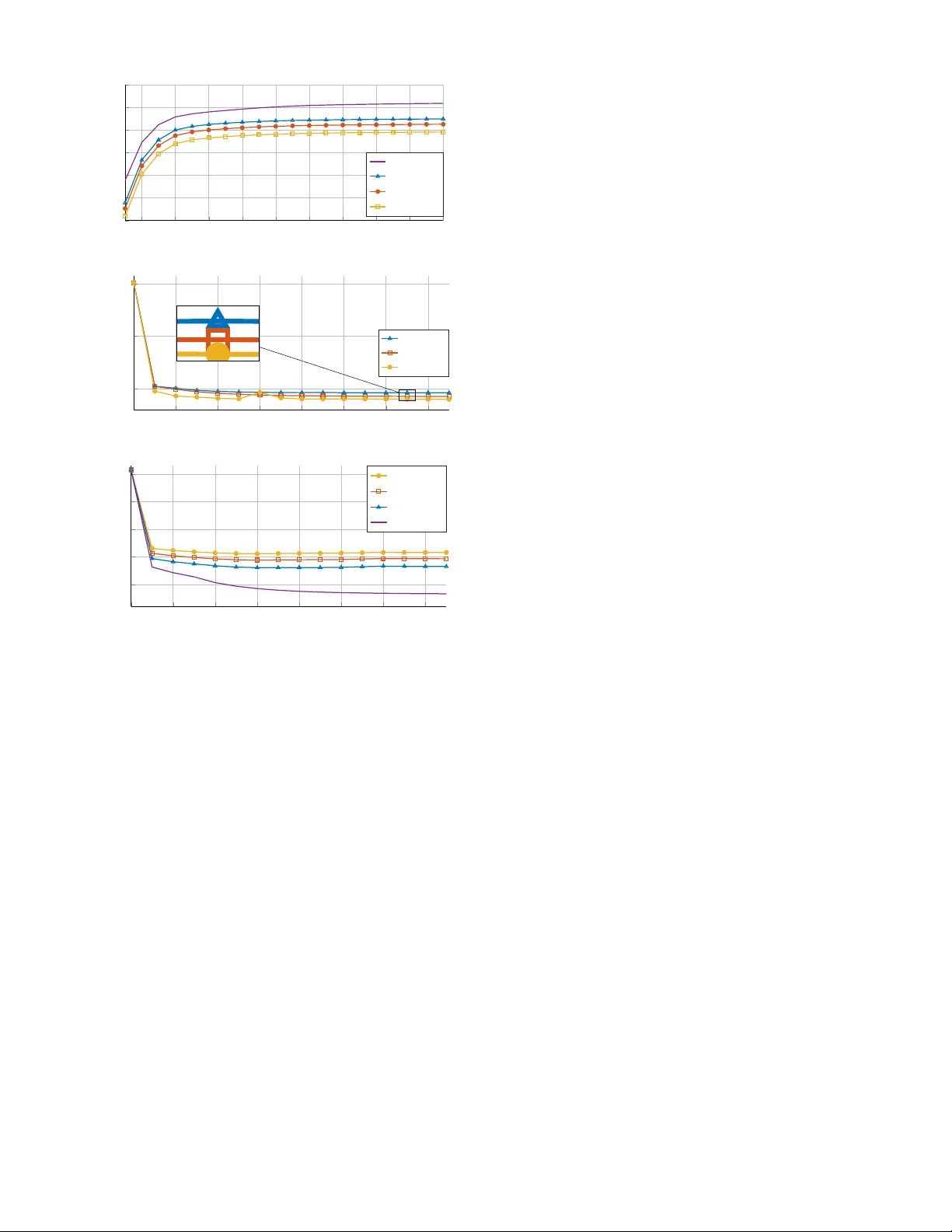
Destructi v e and Constructi v e RIS Beamforming in an ISA C Multi-User MIMO Network Ste ven Ri vetti † , ¨ Ozlem T u ˘ gfe Demir ∗ , Emil Bj ¨ ornson † , Mikael Skoglund † † School of Electrical Engineering and Computer Science (EECS), KTH Royal Institute of T echnology , Sweden ∗ Department of Electrical-Electronics Engineering, TOBB Uni versity of Economics and T echnology , Ankara, T ¨ urkiye Abstract —Integrated sensing and communication (ISA C) has already established itself as a promising solution to the spectrum scarcity pr oblem, even mor e so when pair ed with a r econfigurable intelligent surface (RIS), as RISs can shape the propagation en vironment by adjusting their phase-shift coefficients. Albeit the potential performance gain, a RIS is also a potential security threat to the system. In this paper , we explor e both the positive and negative sides of having a RIS in a multi-user multiple- input multiple-output (MIMO) ISA C network. W e first develop an alternating optimization algorithm, obtaining the active and passive beamforming vectors that maximize the sensing signal- to-noise ratio (SNR) under minimum signal-to-interference-plus- noise ratio (SINR) constraints for the communication users and finite power budget. W e also investigate the destructive potential of the RIS by devising a RIS phase-shift optimization algorithm that minimizes the sensing SNR while preser ving the same minimum communication SINR pr eviously guaranteed by the system. W e further investigate the impact of the RIS’ s individual element failures on the system performance. The simulation results show that the RIS performance-boosting potential is as good as its destructive one and that both of our optimization strategies are hindered by the in vestigated impairments. Index T erms —RIS, malicious RIS, ISA C, MIMO, RIS element failures I . I N T RO D U C T I O N Reconfigurable intelligent surfaces (RISs) hav e captured significant interest from both academia and industry for their ability to control challenging radio propagation en vironments intelligently . By using lo w-cost passi ve reflecting elements that induce a controllable phase-shift to incoming waveforms, RISs can effecti vely steer reflected signals towards desired locations while reducing interference at undesired points [1], [2]. More- ov er , RISs have recently emer ged as a promising technology in integrated sensing and communications (ISA C) applications, increasing the av ailable spatial degrees of freedom. In [3], the sum rate of the communication user equipments (UEs) is maximized under the worst-case sensing signal-to-noise ratio (SNR) constraint. On the other hand, [4] defines a sensing signal-to-interference-plus-noise ratio (SINR) by taking into account the presence of interfering objects along the sensing path: this sensing SINR is then maximized in a weighted fashion alongside minimizing the multi-user interference. Despite their cost-ef fecti ve deployment and potential to enhance wireless communication and sensing performance, RISs present critical physical layer security (PLS) challenges. This work was supported by the SUCCESS project (FUS21-0026), funded by the Swedish Foundation for Strategic Research. RIS H t h s ,k h s,T h r ,k g T arget Hacker BS UEs Fig. 1: A RIS-aided ISA C network where a hacker has hacked into the RIS’ s control circuit. In particular, RISs could potentially be exploited as mali- cious entities that instead compromise communication and sensing performance. [5] gi ves an overvie w of the possible ways in which an illegally deployed RIS can hinder system performance, characterizing signal leakage from the legitimate system to the said RIS and the potential damage of interference attacks launched by the former . Adding artificial noise onto the legitimate system’ s transmitted waveform proves to be an effecti ve strategy in increasing the system’ s PLS, even though the impact of an illegally deployed RIS is still non-negligible. On the other hand, [6] assesses the impact of an active RIS, i.e., a RIS capable of amplifying the impinging signal, onto an Internet of Things network where the RIS aims at minimizing a single device’ s SNR. The authors analyze both the cases of known and unknown malicious RIS identity . A significant challenge is that the attacks are difficult to detect because they are not carried out by generating interfering signals, as in traditional jamming. Instead, they in volv e configuring the RIS to degrade the system’ s performance. In [7], the impact of these silent attacks is demonstrated, further showing how destructi ve beamforming is susceptible to channel state information (CSI) uncertainties. An important albeit often ov erlooked practical consideration about RIS is that individual elements, also known as pixels , may f ail: [8] gi ves an o vervie w of the different types of errors that may arise in a practical RIS implementation and characterizes their impact on the RIS radiation pattern. In [9], the authors propose a failure model to specify the amplitude and phase-shift of faulty elements and propose a diagnostic method while the authors of [11] assess the impact of RIS pixel failures onto downlink localization. In this paper , we consider a multi-user (MU)-multiple-input multiple-output (MIMO) network equipped with an ISA C base station (BS), serving multiple UEs while sensing a target. W e first characterize the potential positiv e impact of a RIS deployment by devising a sensing-centric optimization problem computing activ e and passi ve beamforming vectors that maximize the sensing SNR under UEs’ SINR constraints and a finite power budget. Inspired by [10], this problem is solved through alternating optimization. W e then in vestigate the RIS destructi ve potential when, unbekno wnst to the BS, the sensing SNR is minimized while the same minimum SINR is still guaranteed to the UEs, to make this attack harder to detect. W e further define a pixel fault model and assess its impact on both optimization algorithms. Numerical simulations show that the RIS is equally capable of boosting and degrading the system performances and ho w the performances of both algorithms are hindered by the inv estigated pixel failures. Notation : ⊙ represents the Hadamard (element-wise) prod- uct. Boldface lowercase and uppercase letters denote vectors and matrices. The trace of the matrix X is denoted by T r ( X ) . diag ( x ) represents the stacking of x on the main diagonal of a matrix. [ h ] n : m represents vector elements comprised between the n -th and m -th ones, denoted by h n and h m , of vector h . The notation C N (0 , σ 2 ) represents the zero-mean circularly symmetric complex Gaussian distribution with variance σ 2 . I I . S Y S T E M M O D E L W e consider the RIS-assisted MU-MIMO ISAC network shown in Fig. 1, where a BS, equipped with M transmit and M receiving antennas and possessing digital beamforming capabilities, serves K single-antenna UEs in the downlink while sensing the presence of a target. The system is equipped with a RIS made of N reflectiv e elements, whose phase-shifts are described by the vector θ = [ θ 1 . . . θ N ] ⊤ , where | θ n | = 1 for n = 1 , . . . , N . The static path between the BS and UE k is denoted by h s ,k ∈ C M whereas the static path between the BS and target is denoted by h s,T ∈ C M . The reflected paths are defined in a similar fashion, with h r ,k ∈ C N connecting the RIS and UE k while the target is connected to the RIS via g ∈ C N . Lastly , the BS is connected to the RIS through the channel H t ∈ C N × M . The end-to-end channel between the BS and UE k is defined as h k = h s ,k + H H t diag ( θ ) | {z } ≜ Θ h r ,k . (1) The receiv ed signal by UE k can be described by y k = L X l =1 h H k f l t l + w k , (2) where f l ∈ C M is the precoding vector associated with the l -th stream. W e assume that the information meant for UE k is encoded into stream k , while an additional stream K + 1 is used for sensing purposes. Hence, the total number of streams is L = K + 1 . On the other hand, t l is the complex-v alued unit- power information or sensing symbol and w k ∼ C N (0 , σ 2 k ) is the complex Gaussian receiver noise with variance σ 2 k . As for the sensing performance, the two-way sensing channel is H T = c r H H t Θ gg H |{z} ≜ T Θ H H t + c s h s,T h H s,T | {z } ≜ h s,T . (3) The radar cross sections (RCSs) associated with the two sens- ing paths, which also accounts for their pathloss, are modeled according to the Swerling-I model, that is, c r ∼ C N (0 , δ 2 r ) and c s ∼ C N (0 , δ 2 s ) and they take a single value throughout the transmission. The monostatic sensing observ ation can be modeled as y T = H T Ft + w T , (4) where F = [ f 1 . . . f L ] , t = [ t 1 . . . t L ] ⊤ , and the entries of w T are independent and distrib uted as C N (0 , σ 2 T ) . As for the RIS’ s pixel malfunctioning, we adopt the clustered - biased model defined in [8]: the bias may be caused by bit-flip errors at the computing plane of the RIS or by external en vironmental factors, which can in turn cause a cascade effect onto the neighboring pixel’ s shifters, leading to the clustered nature of the failure. W e collect the neighboring faulty pixels in the set Q . The affected pixels assume a phase-shift at a fixed distance κ from the required one. This is implemented by defining a failure mask m = [ m 1 . . . m N ] ⊤ as [11] m n = ( e j κ , if n ∈ Q , 1 , otherwise . . (5) The faulty RIS phase-shift vector is then obtained as θ fault = θ ⊙ m . I I I . L E G I T I M A T E S E N S I N G S N R M A X I M I Z AT I O N The legitimate reason for deploying the RIS is to improve the system performance. Hence, the BS and RIS jointly maximize the sensing SNR while guaranteeing a minimum SINR to the UEs. The choice of optimization function is motiv ated by the fact that the sensing SNR is expected to hav e a direct proportionality to various sensing tasks, such as detection and tracking. More specifically ,[ ? ], [ ? ] show that the detection probability monotonically increases with the sensing SNR. The sensing SNR can be defined as ρ = P L l =1 ρ l σ 2 T = P L l =1 E n ∥ H T f l ∥ 2 o σ 2 T (6) Similarly , the SINR of the k -th UE is described as SINR k ( θ , F ) = | h H k f k | 2 σ 2 k + P L l =1 l = k | h H k f l | 2 . (7) The sensing SNR maximization problem, solved by the BS under the assumption of a collaborating RIS, is the following: maximize θ , { f l } L l =1 P L l =1 ρ l σ 2 T (8a) subject to SINR k ( θ , F ) ≥ γ k , k = 1 , . . . , K , (8b) L X l =1 || f l || 2 ≤ P , (8c) | θ n | = 1 , n = 1 , . . . , N , (8d) where P is the av ailable transmit power of the BS. This problem is non-con ve x, mainly due to the coupling between the optimization v ariables and the non-con vex unitary modulus constraints. In this section, we will devise an alternating opti- mization (A O) algorithm, which switches between optimizing the precoding vectors and RIS phase-shifts until conv ergence. A. Pr ecoder optimization In this subsection, we will consider the first subproblem of the A O algorithm, which is the problem that retrie ves the optimal precoder F when Θ is fixed. It can be shown that the sensing SNR per stream, ρ l , can be written as ρ l = f H l Γf l , where the matrix Γ is Γ = δ 2 s h H s,T h s,T + δ m h H s,T H H t ΘTΘ H H t + δ ∗ m H H t ΘT H Θ H H t h s,T + δ 2 r H H t ΘT H Θ H H t H H t ΘTΘ H H t (9) and δ m = E [ c r c ∗ s ] . By defining the v ariable W l = f l f H l , we obtain the following problem P 1 := maximize W l ⪰ 0 , ∀ l P L l =1 T r W l Γ σ 2 T (10a) subject to Tr ( W k ˜ H k ) ≥ γ k X l = k T r ( W l ˜ H k ) + σ 2 k ! , k = 1 , . . . , K , (10b) L X l =1 T r ( W l ) ≤ P , (10c) rank ( W l ) = 1 , l = 1 , . . . , L, (10d) where ˜ H k = h k h H k . W e can apply semi-definite relaxation (SDR) to P1 by removing the rank one constraint. The result- ing problem becomes conv ex and can be solved using general- purpose solvers like CVX. During our simulations, we have observed that, for the scenario at hand, the optimal solutions { W opt l } K l =1 hav e rank one. Thus the relaxation is tight and { f opt l } K l =1 can be retriev ed through an eigendecomposition. W e cannot say the same about W L , thus, we employ the rand C method from [12], generating a set Z of randomized solutions that shall be denoted by f rd L . W e further define the set of feasible randomized solutions as S = { f rd L : f rd L ∈ Z , ∥ f rd L ∥ 2 ≤ P − P K k =1 ∥ f opt k ∥ 2 , SINR k ( θ , ˜ F opt ) ≥ γ k , k = 1 , . . . , K } , where ˜ F opt = [ f opt 1 . . . f opt K f rd L ] . The sensing precoding vector is then obtained as f opt L = arg max f rd L ∈S T r f rd L ( f rd L ) H Γ /σ 2 T . (11) B. RIS phase-shift optimization W e now move on to the second part of the A O, where we obtain Θ while F is fixed. W e rewrite ρ l , defined in (6), as ρ l = δ 2 r T r H t f l f H l H H t ΘT H Θ H H t H H t ΘTΘ H + 2 ℜ T r δ ∗ m ΘT H Θ H H t h s,T f l f H l H H t + δ 2 s T r h H s,T h s,T f l f H l . (12) By utilizing the identity T r ( AXBX ) = ( vec X ⊤ ⊤ )( B ⊤ ⊗ A ) vec ( X ) and T = T H , the first term of ρ l can be rewritten as vec ΘTΘ H H H ∗ t H ⊤ t ⊗ δ 2 r H t f l f H l H H t vec ΘTΘ H (13) Then, thanks to the nature of Θ [10], we can write that vec ( ΘTΘ H ) H = diag ( vec ( T )) H ˜ θ , where ˜ θ collects the di- agonal entries of Θ ∗ ⊗ Θ . W e can finally rewrite the first term of ρ l as ˜ θ H Q l ˜ θ , where Q l = ( diag ( vec ( T ))) H H ∗ t H ⊤ t ⊤ ⊗ δ 2 r H t f l f H l H H t × diag ( vec ( T )) . (14) W e apply vec ( ΘTΘ H ) H = diag ( vec ( T )) H ˜ θ to the second term of ρ l as well. Eventually , the sensing SNR per stream, excluding its constant terms, can be further rewritten as ρ l = ˜ θ H Q l ˜ θ + 2 ℜ ˜ θ H p l , (15) where p l = diag ( vec ( T )) H vec δ ∗ m H t h s,T f l f H l H H t . (16) The RIS phase-shift optimization problem under consideration is non-conv ex due to the unit-modulus constraints and the objectiv e of maximizing a con ve x function. T o circumvent this issue, we employ the Minorization-Maximization (MM) algorithm to maximize a lower bound on ρ l [10]. More specifically , we lo wer-bound ˜ θ H Q l ˜ θ by computing its first- order T aylor expansion around the local point ˜ θ ( t ) : ˜ θ H Q l ˜ θ ≥ 2 ℜ b ( t ) H l ˜ θ − ˜ θ ( t ) H Q l ˜ θ ( t ) , (17) where b ( t ) l = Q l ˜ θ ( t ) . Then, ignoring the constant terms, the objectiv e function can be written as 1 σ 2 T L X l =1 2 ℜ b ( t ) H l ˜ θ + ℜ ˜ θ H p l = 1 σ 2 T L X l =1 2 ℜ θ H Σ b ( t ) l + Σ p l θ , (18) where Σ b ( t ) l ∈ C N × N is a matrix built by stacking the elements of b ( t ) l . W e define the variable ˆ Θ = ˆ θ ˆ θ H , where ˆ θ = [ θ ⊤ , 1] ⊤ and h r ,k = diag ( h r ,k ) . Then, the second subproblem of the A O algorithm is P 2 := maximize ˆ Θ ⪰ 0 1 σ 2 T L X l =1 2 T r Ξ ( t ) l ˆ Θ (19a) subject to h ˆ Θ i n,n = 1 , n = 1 , . . . , N + 1 , (19b) T r R k,k ˆ Θ ≥ γ k X l = k T r R k,l ˆ Θ + σ 2 k (19c) rank ˆ Θ = 1 , (19d) Algorithm 1: Sensing SNR maximizing A O algorithm 1: Initialize: Randomly generate θ (0) , t ← 0 2: repeat 3: Solve the relaxed version of P1 with θ = θ ( t ) 4: Retriev e F ( t +1) through Gaussian randomization 5: Solve the relaxed version of P2 with F = F ( t +1) 6: Retriev e θ ( t +1) through Gaussian randomization 7: t ← t + 1 8: until ρ ( t ) − ρ ( t − 1) ≤ ν 9: Output: θ opt , F opt where R k,l = h H r ,k H t f l f H l H H t h r ,k h H r ,k H t f l f H l h s ,k h H s ,k f l f H l H H t h r ,k | h H s ,k f l | 2 , (20) Ξ ( t ) l = " Σ b ( t ) l + Σ p l 0 N × 1 0 1 × N 0 # . (21) By removing the rank-one constraints, the relaxed problem becomes con vex. Hence, it can be solved by CVX, and we can retriev e a good sub-optimal solution via Gaussian randomization. Following the rand C method, we generate a set R of randomized solutions denoted by ˆ θ rd . W e normalize them as η ( ˆ θ rd ) = ˆ θ rd / ˆ θ rd N +1 to ensure that the last element is one and then we define ˜ η ( ˆ θ rd ) n = e j ∠ η ( ˆ θ rd ) n , n = 1 , . . . , N , to meet the unit modulus constraint. W e then define the set of feasible randomized solutions as E = n ˜ η ˆ θ rd : ˆ θ rd ∈ R , SINR k ˜ η ˆ θ rd , F opt ≥ γ k , k = 1 , . . . , K o , the RIS phase-shifts are recovered as ˆ θ opt = arg max ˜ η ( ˆ θ rd ) ∈E 2 σ 2 T L X l =1 T r Ξ ( t ) l ˜ η ˆ θ rd ˜ η ˆ θ rd H . (22) The steps of the A O algorithm are outlined in Algorithm 1. I V . M A L I C I O U S R I S S E N S I N G S N R D E G R A D A T I O N W e assume that the RIS control circuit has been hacked. The hacker aims to degrade the sensing SNR so that the sensing target can go undetected. T o make the hacker’ s action hard to detect, the UEs are still guaranteed a minimum SINR. Motiv ated by the collaboration between the BS and RIS, we assume that the hacker has access to the optimal precoders F opt . Additionally , we consider the worst-case scenario in which perfect CSI is available to the hacker . Hence, the hacker models the cascaded channel as h k = h s ,k + H H t h r ,k θ . According to these assumptions, the ρ l can be rewritten as ρ l = δ 2 r f H l H H t G θ 2 H H t G θ 2 + θ H M l θ + δ 2 s f H l h H s,T h s,T f l , (23) where G = diag ( g ) , (24) M l = G H H t δ ∗ m h s,T f l f H l + δ m f l f H l h H s,T H H t G . (25) The sensing-degrading selection of Θ is obtained by solving the problem P 3 := minimize θ P L l =1 ρ l σ 2 T (26a) subject to SINR k ( θ , F opt ) ≥ γ k , k = 1 , . . . , K , (26b) | θ n | = 1 , n = 1 , . . . , N . (26c) This problem is non-con vex and, therefore, challenging to solve. Howe ver , we will demonstrate that each non-con vex term of the objectiv e function can be reformulated in a manageable manner, enabling us to solve P 3 using the conv ex- concav e procedure (CCP) [13]. The first term of ρ l is the product between individually con vex terms of θ . W e decouple those terms by introducing the variables s = [ s 1 . . . s L ] ⊤ and r , redefining ρ l by removing the constant term as ρ l = δ 2 r s 2 l r 2 + θ H M l θ , and adding the constraints | f H l H H t G θ | 2 ≤ s 2 l ∥ H H t G θ ∥ 2 ≤ r 2 , l = 1 , . . . , L. (27) The product between s 2 l and r 2 is still noncon vex, thus, we rewrite it by lev eraging the square-completion method: ρ l = δ r 2 ( s 2 l + r 2 ) 2 − δ r 2 s 4 l − δ r 2 r 4 + θ H M l θ . (28) The last term is a source of non-con vexity because, albeit Hermitian symmetric, M l is not necessarily positive semi- definite (PSD). W e then introduce the auxiliary variables α = [ α 1 . . . α L ] ⊤ and redefine ρ l as ρ l = δ r 2 ( s 2 l + r 2 ) 2 − δ r 2 s 4 l − δ r 2 r 4 + α l (29) with the additional constraints ˆ θ H M l 0 N × 1 0 1 × N 0 | {z } ˆ M l ˆ θ ≤ α l , (30) where ˆ θ = [ θ ⊤ , 1] ⊤ . W e then apply the CCP method [13] to (30) and obtain ˆ θ H ˆ M (+) l ˆ θ + 2 ℜ ˆ θ ( t ) H ˆ M ( − ) l ˆ θ ≤ α l + ˆ θ ( t ) H ˆ M ( − ) l ˆ θ ( t ) , l = 1 , . . . , L, (31) where ˆ M (+) l , ˆ M ( − ) l are respectiv ely the positiv e and negati ve semi-definite parts of ˆ M l and ˆ θ ( t ) being a local point. The second and third terms of (28) are concav e and are then locally upper bounded by their first-order T aylor expansion. W e define an approximated version of ρ l around the local point ( s ( t ) , r ( t ) , ˆ θ ( t ) ) by also removing the constant terms: ˜ ρ ( t ) l = δ r 2 ( s 2 l + r 2 ) 2 − 2 δ r s ( t ) , 3 l s l − 2 δ r r ( t ) , 3 r + α l . (32) The feasible-point pursuit successive conv ex approximation procedure [14] is applied to (26c), decoupling it into ˆ θ n 2 ≤ 1 + ξ n , n = 1 , . . . , N , (33a) ˆ θ ( t ) n 2 − 2 ℜ ˆ θ ∗ n ˆ θ ( t ) n ≤ ξ N + n − 1 , n = 1 , . . . , N , (33b) where ξ = [ ξ 1 . . . ξ 2 N ] ⊤ is a vector of auxiliary variables. The minimum SINR constraint (26b) is written as γ k ˆ θ H U k ˆ θ + σ 2 k − ˆ θ H R k,k ˆ θ ≤ 0 , (34) where U k = h H r ,k H t F − k F H − k H H t h r ,k h H r ,k H t F − k F H − k h s ,k h H s ,k F − k F H − k H H t h r ,k h H s ,k F − k F H − k h s ,k . (35) The notation F − k ∈ C M × L − 1 indicates a matrix containing all the precoding vectors except the one assigned to the k -th UE. The constraint in (34) is then con ve xified as γ k ˆ θ H U k ˆ θ + σ 2 k − 2 ℜ ˆ θ ( t ) H R k,k ˆ θ + ˆ θ ( t ) H R k,k ˆ θ ( t ) ≤ v k , k = 1 , . . . , K , (36) where v = [ v 1 . . . v K ] ⊤ are auxiliary v ariables. Lastly , (27) are locally approximated as | τ l ˆ θ | 2 + s ( t ) , 2 l − 2 s ( t ) l s l ≤ 0 , l = 1 , . . . , L, (37) ∥ ˆ H ˆ θ ∥ 2 + r ( t ) , 2 − 2 r ( t ) r ≤ 0 , (38) where τ l = [ f H l H H t G , 0] and ˆ H = [ H H t G , 0 M × 1 ] . W e are now finally able to define the conv ex reformulation of P 3 : P 4 := minimize ˆ θ , v , ξ , s ,r P L l =1 ˜ ρ ( t ) l σ 2 T + λ ( t ) ( || ξ || + || v || ) (39a) subject to ˆ θ N +1 = 1 , (39b) (31) , (33) , (36) , (37) , (38) , (39c) ξ , v , s , r ≥ 0 , (39d) where λ ( t ) is a penalty factor adjusting the impact of the auxiliary v ariables onto the optimization function. The iterativ e procedure is described in Algorithm 2, with ν being a preset tolerance lev el. Algorithm 2: Sensing SNR degradation algorithm 1: Initialize: Set t = 0 and λ (0) , randomly generate θ (0) , s (0) l = f H l H H t G θ (0) 2 , r (0) = H H t G θ (0) 2 2: repeat 3: Retrie ve s ( t +1) , r ( t +1) , ˆ θ ( t +1) by solving P4 4: λ ( t +1) = min µλ ( t ) , λ max 5: t ← t + 1 6: until ˆ θ ( t ) − ˆ θ ( t − 1) ≤ ν , ∥ ξ ∥ ≤ ν, ∥ v ∥ ≤ ν 7: Output: θ opt (10,0) BS (50,100) (100,80) (150,20) (140,80) T ar get RIS (100,120) (140,120) x y UEs Fig. 2: Illustration of the simulation setup. 2 4 6 8 10 12 14 16 18 20 15 20 25 30 t ρ [dB] N = 25 N = 20 N = 15 Fig. 3: Alg. 1 ρ maximization vs t for different values of N . V . N U M E R I C A L R E S U LT S In this section, we will demonstrate the ability of the RIS to either improve or degrade the system performance. The simulation results are av eraged over 500 independent channel realizations with |Z | = |R| = 1000 . The number of BS antennas is M = 30 and the number of UEs is K = 4 . Unless otherwise specified, N = 15 , with a number of faulty pixels equal to |Q| = 4 . The static paths h s ,k , h s,T , and g are independent and identically distributed (i.i.d.) Rician fading with a K-factor of 10 , whereas H t is a scattering-free line of sight (LoS) channel. Lastly , h r ,k are i.i.d. Rayleigh fading. The static and reflected path RCS variances are set to δ 2 r = δ 2 s = 10 − 5 whereas δ m = 9 · 10 − 6 . W e assume an equal minimum SINR for all UEs, denoted by γ and it is equal to 2 , unless otherwise specified. The BS av ailable power is 3 dBW and the UEs and sensing noise variances are set to σ 2 k = σ 2 T = 1 . W e consider the 2 D area shown in Fig. 2, where the UEs are randomly distributed within the highlighted area. 2 4 6 8 10 12 14 16 18 20 10 12 14 16 18 20 22 t ρ [dB] not faulty κ = π / 6 κ = π / 4 κ = π / 3 Fig. 4: Alg. 1 ρ maximization vs t in presence of failures. 0 2 4 6 8 10 12 14 − 20 0 20 t ρ [dB] γ = 2 γ = 1 γ = 0 . 5 0 2 4 6 8 10 12 14 − 20 0 20 t ρ [dB] γ = 2 γ = 1 γ = 0 . 5 Fig. 5: Alg. 2 ρ minimization vs t for different values of γ . 0 2 4 6 8 10 12 14 − 20 − 10 0 10 20 t ρ [dB] κ = π / 3 κ = π / 4 κ = π / 6 not faulty Fig. 6: Alg. 2 ρ minimization vs. t in the presence of failures. A. Sensing SNR maximization W e will first test the sensing SNR maximization capabilities of Algorithm 1. Fig. 3 shows that ρ is a monotonically increas- ing function of the number of iterations t and con ver gence is reached in 20 iterations. A larger RIS size allows us to reflect more energy towards the target, resulting in a higher ρ . There are diminishing returns in increasing N . When N goes from 15 to 20 , the final value of ρ increases by 5 dB, whereas when N goes from 20 to 25 the increase is halved. Fig. 3 shows the impact of clustered-biased pixel failures [8] onto Algorithm 1. This kind of failure does not alter the maximization trend, but leads to con vergence to a lower ρ -value. For example, a big phase bias magnitude of π / 3 attains a ρ value only 2 dB lower than the one obtained with a perfectly functioning RIS, showing that nonideal hardware can be tolerated by the system. B. Malicious RIS action Fig. 5 shows how Algorithm 2 causes SNR reduction. One iteration is sufficient to obtain a 40 dB SNR reduction w .r .t. to the maximized value obtained in the previous section. This re- duction further increases in the span of 15 iterations, reaching a final value around − 22 dB. Such an attack is complicated to detect as the communication SINRs are untouched, thus the communication UEs will not see any dif ference in their service. Reducing γ would improve the SNR reduction at the expense of a higher chance of the attack being discovered. Howe ver , a 50% reduction in γ corresponds to a mere 2 dB SNR reduction. W e attribute the bump at iteration 6 of the SNR curve with γ = 0 , 5 to an outlying realization among the av eraged ones: it is worth mentioning that said bump does not hinder the SNR con ver gence process and ρ at iteration 15 is lower than ρ at iteration 6 . Fig. 6 assesses the impact of the considered pixel failures model onto Algorithm 2. Contrary to what we observed in Fig. 4, faulty RIS hardware has a bigger impact on the final sensing SNR. A bias of π / 6 is sufficient to induce a 10 dB penalty onto the final value of ρ , making this algorithm less tolerant towards faulty hardware. V I . C O N C L U S I O N S W e hav e in vestigated the potential benefits and harm of having a RIS in an ISAC MU-MIMO network. The positiv e side of the RIS’ s presence has been in vestigated by devising an optimization algorithm maximizing the sensing target SNR under the communication SINR constraints and a finite power budget. The negati ve side arises when a hacker takes control of the RIS, computing its phase-shifts to minimize the target SNR, under the same SINR constraints. The hacker can make the sensing target practically in visible to the system, which is a major concern if ISAC is meant to be used for surveillance. W e have further considered the presence of clustered pixel failures in the RIS. Numerical simulations hav e exemplified how great both potentials are and how the in vestig ated pixel failures caused the final SNR value to be at a fixed offset from the one obtained with an unimpaired RIS. R E F E R E N C E S [1] G. C. Alexandropoulos, N. Shlezinger, and P . Del Hougne, “Reconfig- urable intelligent surfaces for rich scattering wireless communications: Recent experiments, challenges, and opportunities, ” IEEE Communica- tions Magazine , vol. 59, no. 6, pp. 28–34, 2021. [2] K. Chen, C. Qi, O. A. Dobre, and G. Y . Li, “Simultaneous beam training and target sensing in ISAC systems with RIS, ” IEEE T ransactions on W ireless Communications , 2023. [3] R. Liu, M. Li, and A. L. Swindlehurst, “Joint beamforming and reflection design for RIS-assisted ISAC systems, ” in 2022 30th Eur opean Signal Pr ocessing Conference (EUSIPCO) . IEEE, 2022, pp. 997–1001. [4] K. Zhong, J. Hu, C. Pan, M. Deng, and J. Fang, “Joint wa veform and beamforming design for RIS-aided ISAC systems, ” IEEE Signal Pr ocessing Letters , vol. 30, pp. 165–169, 2023. [5] Y . W ang, H. Lu, D. Zhao, Y . Deng, and A. Nallanathan, “W ireless com- munication in the presence of illegal reconfigurable intelligent surface: Signal leakage and interference attack, ” IEEE W ireless Communications , vol. 29, no. 3, pp. 131–138, 2022. [6] Z. Lin, H. Niu, K. An, Y . Hu, D. Li, J. W ang, and N. Al-Dhahir, “Pain without gain: Destructive beamforming from a malicious RIS perspecti ve in IoT networks, ” IEEE Internet of Things Journal , 2023. [7] S. Rivetti, ¨ O. T . Demir, E. Bj ¨ ornson, and M. Skoglund, “Malicious reconfigurable intelligent surfaces: How impactful can destructive beam- forming be?” arXiv preprint , 2024. [8] H. T aghvaee, A. Cabellos-Aparicio, J. Georgiou, and S. Abadal, “Error analysis of programmable metasurfaces for beam steering, ” IEEE Jour - nal on Emer ging and Selected T opics in Cir cuits and Systems , vol. 10, no. 1, pp. 62–74, 2020. [9] J. Zhang, X. Hu, and C. Zhong, “Phase calibration for intelligent reflecting surfaces assisted millimeter wave communications, ” IEEE T ransactions on Signal Pr ocessing , vol. 70, pp. 1026–1040, 2022. [10] Z.-M. Jiang, M. Rihan, P . Zhang, L. Huang, Q. Deng, J. Zhang, and E. M. Mohamed, “Intelligent reflecting surface aided dual-function radar and communication system, ” IEEE Systems Journal , vol. 16, no. 1, pp. 475–486, 2021. [11] C. Ozturk, M. F . K eskin, V . Sciancalepore, H. W ymeersch, and S. Gezici, “Ris-aided localization under pixel failures, ” IEEE T ransactions on W ireless Communications , 2024. [12] Z.-Q. Luo, J. F . Sturm, and S. Zhang, “Multivariate nonnegati ve quadratic mappings, ” SIAM Journal on Optimization , vol. 14, no. 4, pp. 1140–1162, 2004. [13] G. Zhou, C. Pan, H. Ren, K. W ang, M. Di Renzo, and A. Nallanathan, “Robust beamforming design for intelligent reflecting surface aided MISO communication systems, ” IEEE W ireless Communications Letters , vol. 9, no. 10, pp. 1658–1662, 2020. [14] O. Mehanna, K. Huang, B. Gopalakrishnan, A. Konar , and N. D. Sidiropoulos, “Feasible point pursuit and successive approximation of non-con ve x qcqps, ” IEEE Signal Processing Letters , vol. 22, no. 7, pp. 804–808, 2014.
Original Paper
Loading high-quality paper...
Comments & Academic Discussion
Loading comments...
Leave a Comment