Consideration of Vehicle Characteristics on the Motion Planner Algorithm
Autonomous vehicle control is generally divided in two main areas; trajectory planning and tracking. Currently, the trajectory planning is mostly done by particle or kinematic model-based optimization controllers. The output of these planners, since …
Authors: Syed Adil Ahmed, Taehyun Shim
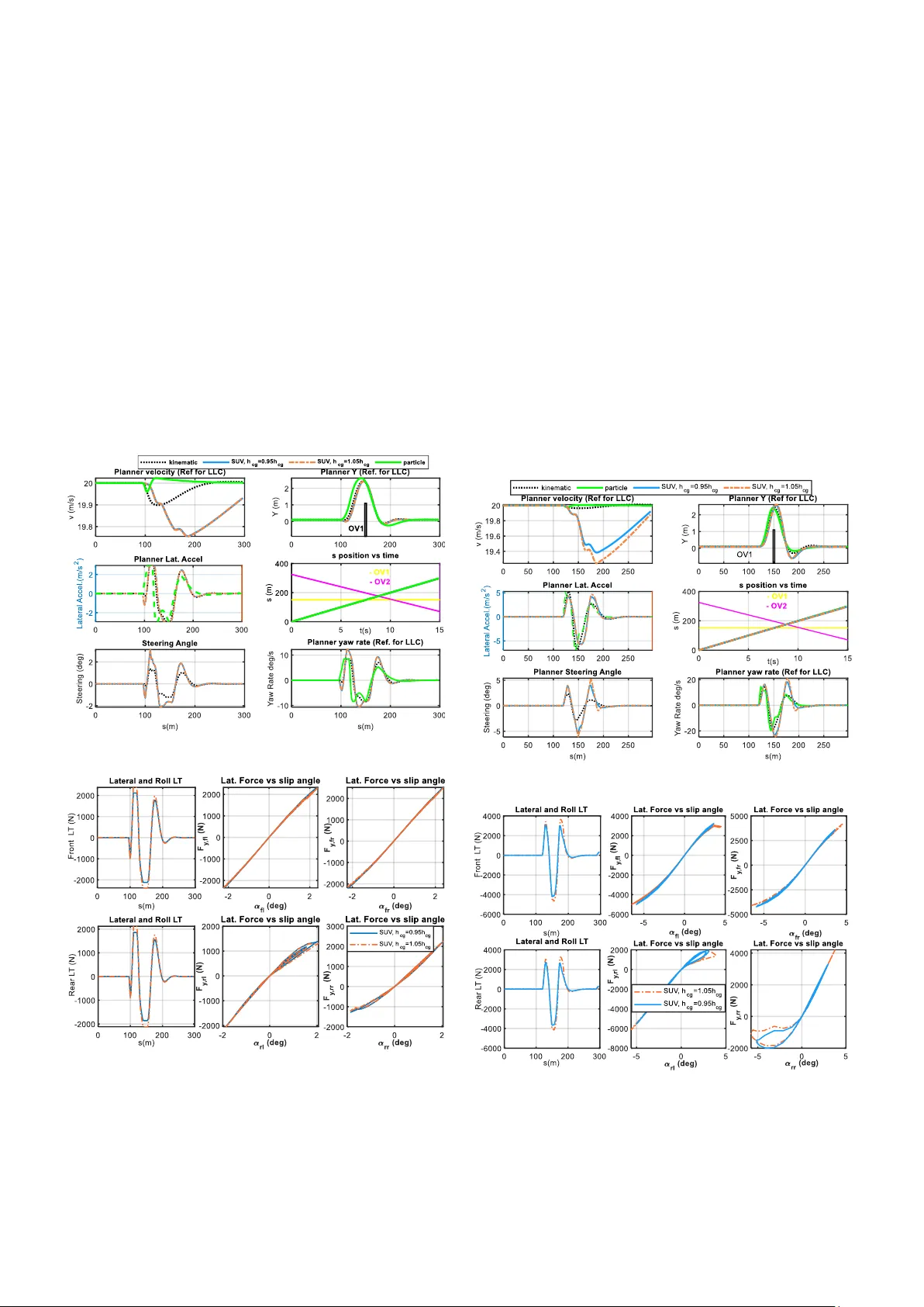
© 20 24 the authors. This work has bee n accepted to IFAC (ME CC 202 4, Chica go) for publication under a Creative Co mmons Licence CC- BY - NC - ND" C o n s i d e r a t i o n o f V e h i c l e C h a r a c t e r i s t i c s o n t h e M o t i o n P l a n n e r A l g o r i t h m Syed Adil Ah med and Taehyun Shi m* University of Michigan Dearborn, Dea rborn , MI 8030 , USA (e -mail: adilsa@umich.ed u & tshim@umich.edu ). *Correspon ding author Abstract : Autonomous vehicle control is ge nerally divided in t wo main areas; trajectory planning and tracking. Currently, the trajecto ry planning is mostly done by particle or kinematic model-based opt imization co ntrollers. The outpu t of the se planners, s ince they do not consider CG height and its e ffects , is n o t unique for different vehicle ty pes, especiall y for hig h CG vehicles. A s a result, t he tra cking co ntroller may have to work hard to avoid vehicle handling and co mfort constraints while trying to realize these sub - optimal trajector ies. T his paper tries to address this p roblem by co nsidering a planner w it h simplified double track model with estimation of later al and roll based load transfer using s teady state equations and a simplified tire model to reduce solver workload. The d eveloped planner is compared with the widely used particle and kinematic model p lanners in collision avoidanc e scenario s in b oth high and l ow acceleratio n conditions and with different vehicle heights. Keywords : Motio n planning, vehicle d ynamics, nonlinear model pred ictive control ( NMPC) , autono mous vehicles, lateral and roll lo ad transfer effects . 1. INTRODUCTI ON Research on a utonomous vehicle (AV) control is an active re search topic. In this area, m o tion planning for safe an d efficient ve hicle path is a necessity s tep for level 4 o r above autonomous vehicles. Motion planni ng has b een studied extensively f o r a utonomous vehicles and a lot of met hods exists for tackling this pro blem ( survey paper ( Paden et al., 2016)). These methods include sampling methods like A* and RRT* (Karaman & Frazzoli, 201 1), vehicle velocit y a nd path decoupling (Kant & Zucker, 1986; Shi et al., 2021) and optimization function-based methods (MPC, polynomial functions and others) ( Falcone et al., 2008; Weiskircher et al. , 2017). Amongst all of these methods th e optimization-based methods, and in particular the Model P redictive Control (MPC), p rovides the most guarantees o f optimal sol ution and also the ab ility to place ph ysical an d actuator constraints to the problem. Hence, methods using MPC f or traj ectory p lanning are considered in this paper . Amongst th e methodologies for AV control, the most used method involves a hierarchy-based co ntrol scheme. Here, t he planning is an upper-level co ntrol and tracking is the l ower level control. Fig. 1 shows a general flow chart view of the control scheme. In this scheme, the planner constitutes mostly a simple model. There are p article models used in (Falcone et al., 2008; Weiskircher et al., 2017). Here constraints ar e added for acce leration using th e friction circle an d limited by , and the cascaded ac tuator limit co nstraint on t he control i nputs of acceleration and yaw rate. In (Weiskircher et al., 2 017) it is suggested that the par ticle-based planner ca n b e used for any range of acceleration, but, for l ess significant trac ki ng errors i t is s uggested to co nsider . In ad dition, there are also ki nematic planner m od els used, where aga in th e same constraints a s t he particle planner are used. But these models differ from the particle m od el as they contain infor mation of vehicle wheelbase and use Acker man steering a ngle relation s for y aw rate. As a result, they are used for path planning of large vehicles, specificall y a t low speeds (Oliveira et al. , 2020) , and for s maller vehicles (like sedan or SUV) ( P olack et al., 2017) , (Sun et al., 2022). Figure 1 : A hierarchical approach to AV control For the hierar chical control sche me, the planner co nstitutes a simple model. This is because planners are tasked with a nonlinear task of findi ng an op timal path tha t avoids an obstacle, follows road cur vature and at the same time also m eet cascaded p hysical/actuator and environmental co nstraints. As a result, a simple model (hav ing less states) allows a reduction in nonlinearity and a more likel y real-time implementation, as the overall planner cost is smaller (Ferreau, 2011) . Furthermore, the use of a si mpler model in the planner is further m ade possible by use of a nonlinear higher order m od el in the tracker, which co nsiders tire nonli nearity and mostly full car 7DOF+ models. These track in g co ntrollers w o rk at a fast er rate (0.0 5s or lo w er) than the p lanner and ensure that a r ealistic actuator output meeting the actuator constraints is delivered, while also tr ying to follow the planner traject ory. But, by using a simple planar particle model (3DOF) in the motion p lanner, we compromise vehicle trajec tory trac king, handling and driver comfort . This is because the planner generates the sa me reference t rajectories for different t ypes of vehicles, which would imply t hat a m i nivan o r a sed an would be expected to carry out a maneuver (for exam ple, double lane change or taking a sharp curve) in the same way. At lo wer speeds, it may be possible that the same reference trajector ies are used for bo th vehicles. But, at h igh speeds or em er gency maneuvers, a sedan, having a very lo w CG (ce nter of gravity) position, can prob ably use the trajectory outputted b y the particle m odel-based planner, b ut a minivan t hat has a higher CG, m ass, and inertia would be prone to large load transfers, roll and discomfort. T herefore, in order to output unique trajectories for diff er ent vehicle ty pes, there is a need for adding some for m of high er order modelling/modifications, especially at higher ac celerations and limit maneuv ers. T his use of higher-order models in the plan ner for limit maneu vers is also recommended by Polack et al. in (Altché, 2017) , wh ere a co mparison bet ween kinematic and d ynamic (9DOF) based planners is d one and it is concluded that the for mer is o nly valid till lateral acceleration limits. The use of higher ord er model as a pla nner could b e o ne way of addressing the proble m highlighted above. Another approach is the amalgamation of the planner and tracker to create an integrated system (Laurense & Gerd es, 2022 ) (F ig . 2), which us es a hi gh order model (such as a bic ycle or a double track m odel) in the integrated system. This ap proach claims that the hierarchical AV control ( F ig . 1) results in conservative r eferences from the planner due to constra ints used to reduce infeasibility of planner reference, for exampl e steering co nstraint for rollover p rotection. But the integration of the p lanner a nd tracker results in the requirement that the single co ntroller needs a fast update frequency to w ork with vehicle actuators, while al so including nonli nearity o f vehic le model and tire model and satisfyin g the mostly non -convex collision avoidance constr aints. These are competing objectives, which req uire a com p romise, which is mostl y d one on the modeling sid e. In (Laurense & Gerdes, 2022) the authors use an integrated planner and tracker with a cascaded bicycle and point mass model for aggressive emergency maneuvers. The cascaded model is required since without it the real-time i mplementation of the controller becomes a n issue, and the pr ediction hori zon n eeds to be compromised (reduced). To the authors knowledge, no real-time integrated planner an d tracker w ith nonlinear double track model, (which considers lateral and roll based load transfer), exists, and it is thought that this is becau se o f the large co mputation tim e required for such a controller. In this w o rk we will use the AV control scheme highlighted in Fig . 1, as it allows more freedom to modify vehicle models without a penalty for the real-ti me implementation . Using this scheme, we co mpare our newly develop ed planner and reference plan ners (kinematic and particle) to show that the reference trajectories f r om motion planners need to consider the vehicle charac teristics (s uch as size), particularly for a larger vehicle, like an SUV. Ou r new planner considers a novel double tr ack model with s implifications of stead y-state latera l and roll load transfer, a simplified tire m o del , and the removal of wheel speed states. This model is also compared with an 8DOF model to show its accurac y, and this modification allows the planner to be real-time compatible and output m o re optimal reference trajectories. T he new planner is compared with t he reference planners in two collision avoidance scenarios to sho w that trajectories d iffer between the re ference and the new planners . Figure 2 : Integrated planner and tracke r for AV Contro l In this work, the reference planner model is introduced in section 2. In section 3, the new pla nner model is sho wn together with its co mparison to th e 8DOF model. T hen in section 4 the i mplementation of the new planner is highlighted. Finally, i n sectio n 5 and 6, the analysis o f the simulated res ults and a conclusion is provided , respectively. 2. REFERENCE PLAN NER MODELS The reference planner is based on a particle model or a kinematic bicycle model with yaw rate and steeri ng respectively being one of t he inputs and acceleration bein g the other input for bo th models. Both models can be built o n the Frenet coord inate system, allo w ing easier cur ve handling. 2.1 Particle Mo del Like the particle m odel in (Falco ne et al., 2008; Weiskircher et al., 20 17), this particle model is constructed with yaw rate, and acceleration, , b eing input s to it. The m o del, (1), also consists of 6 states, where is the tangential velocit y, is the yaw error b etween particle and reference ya w, is the lateral position erro r between ve hicle a nd reference a nd is the distance traveled by partic le alo ng the refere nce path. The last two state s are used for enfo rcing collision con straints, with being time and is the slack variable for collision avoidance constraint enforcement. Figure 3: Kinematic bicycle model 2.2 Kinema tic model The kinematic bicycle model, Fig. 3, for the planner considers the ve hicle w heelbase and its ef fect on yaw. And due to the reference p oint being the CG and not th e r ear axle, the side slip angle, , also needs to be considered for yaw rate calculat ion. Also, the inputs to the model are, , acce leration and , steering. Otherwise, the model is like the particle model. 3. NEW PLANNER MO DEL DEVEOPME NT The reference plann er s, as show n in (1) and (2) do not co nsider vehicle inertia s, and the size of vehicle, h ence there is no differentiation bet w een planning for lar ge or small vehicles . Due to this conditio n, it is possible that the trajectory offer ed by this plann er i s not optimal for the vehicle. Hence lea ving the tracki ng c ontroller to work out a s uboptimal path t hat doesn’t follow the planned traj ectory or get overworked. In o rder to avoid these issues, we con sider a si mple for m of a double tr ack model with the simpli fied tire model. T he model has inputs o f steering, and total lo ngitudinal force , . Hence, removing the fast wheel speed states. In order to calculate the vertical forces correctly , the plann er model considers steady state roll moments for calculating lateral load transfer for fro nt and rear , and . Using the se lo ad transfer ter ms w e can cr eate better estimates for our vertical force ca lculations. Where, , m is the mass, is th e suspension stiffness, is the roll angle, and are the front and rear wheelbase lengths, is the longitudinal acceleration and is the lateral acceleratio n. The nonlinear dif ferential equations gover ning this motion planner are as shown in (6). T he model includes state s of longitudinal velocit y, , lateral velocit y, , yaw rate, , and the curvilinear coordinates of and co llision avoidance related constraints of . In (6), , follows the simplified tire model provided in (Adireddy et al., 20 10) and is sho wn in (7). Where, , and . Here, a and b are quadratic polynomial co efficients o f cornering s tiffness calc ulated fro m Magic Formula t ire data for each ve hicle. And is the nominal tire force. Fig . 4 sho ws that the m od el in (6) closely follows the non linear 8DOF model with Pacej ka tire m odel. This check ensures that the output of states we g et from the planner are realistic. Also, it allo ws us to later check other refere nce planners for trajectories (Y position, yaw rate and spee d) that have conflicting references (like, some planners might have a Y position that has a very differe nt yaw rate tha n what would b e required by t he vehicle). T his is necessary, to limit the sco pe, as there is no tracking con troller developed in this paper. Figure 4: 8DOF vs (6) in 0.5Hz sine steer at initial speed of 20 m/s 4. IMP LEMENTATION OF T HE NMPC PLANNER The objective of a planner is to devise a path and m o tion profile that allows road curvature follo wing, avoids ob stacles, follows constraint s (enviro nment, speed limits and actuator ) and provides a comfortable path. The following is the NMPC cost function and constraint s: Where, and s.t. In ( 8) the first term fro m left i s for tracking of outputs, whe re lateral offset o f zero and ref erence speed tracking i s desired. The second ter m looks at reducing jerky i nput values by penalizing rate of change o f steering and total longitudinal force, . The third term aims to reduce the to tal output of control values to ens ure an energy e fficient and economic al control. The rightmost term in (8), aims at penalizing excessive slip angle usage by the pla nner for all tires. This is because the tire model (7) saturat es out as a constant value, and it is possible that the controller uses more than the required steeri ng when above 1.7 5 . 4.1 Collision Avoidance (CA) co nstraint The collision avoidance constraint is p rovided in ( 8e ) and involves an ell ipse based Euclidean nor m (Weiskirc her et al ., 2017) . During the prediction horizon, the objects (OV) in Frenet coordinates are assumed to travel at constant tangential and normal accelerations, start at an initial position and speed . This g ive s the following object position in s and frame: And then the main collision avoidance constraint is ellip se based Euclidean norm (8 e). Where, for each obstacle, i, an d an d . Here, is a free variable and . In fig. 5 is a later al buffer which is kep t as 0.15 m i n this work. Figure 5 : Ellipse based Euclidean norm 4.2 Impleme ntation Casadi 3.6.5 with MAT LAB is used to solve the op timization problem. Casadi is a free and open-source symbolic framework for automatic differ entiation and optimal control. The nonlinear opti mization is solved using IP OPT solver, which is the default solver in Casadi. To speed up the solver, warm start procedure is used and multiple shooting discretization using Runge Kutta 4 method is used to re construct the nonlinear proble m. T he sample time ( is set to 0.1s, w hile the prediction horizon is varied for each simulation. 5. RESULTS AND DI SCUSSION To evaluate the different m ot ion plann er models a n ob stacle avoidance scenario is created, that considers a static vehicle in ego lane and an oncoming traffic ve hicle in o pposite lane. The selected scenario causes the planners (reference a nd developed) to create their ow n required path around the obstacles. For these scenarios, to see the effect of vehicle height, the developed co ntroller is simula ted with two version s of the SUV vehicle, h = 0.95 and h = (loaded at top) . Also, the trac king control is not used in this w or k, and t he results will look to analyze p lanner outputs, speci fically t he planner outputs of yaw rate, v ehicle position Y and velocit y . These outputs for m r eferenc es for tracking control (like in (Adireddy et al., 2010) ), and their o ptimality ensures t hat th e tracking contro l is not overworked or follo w s an infeasible trajectory. Figure 6 : Collision avoidance scen ario u sed to ev alu ate th e plan ners For the r eference planners, a p roblem like (8) is so lved, with the first t hree ter ms in (8) . of the pr oblem is sli ghtly modified by considering co nstraints like ( 8c), (8d) and (8 i) for the reference p lanner inp uts and re moval of co nstraint (8 h). T he sample time and p rediction horizo n are sa me as for the ne w planner. The lo ok ahead distance of 50m , ( where N = 25), is selected for the co ntroller, which results in linear tire r egion operation for the planners . To ensure linear r egion operation all planners have an add ed constraint of Fig . 7 shows the state plot of the planners, while Fig. 8 shows that the maneuver is performed in a linear tire domain with a small a mount of lo ad tran sfer (LT ) . It is evident that a l l planners can navigate around the t wo obstacles in a ti mely fashion, albeit with small differences i n the particle and kinematic plann er o utputs. T he p article planner p rovides a much di fferent re ference for th e tracking control, as it does no t consider vehicle i nertia or understeer gradient. The neutral steering ki nematic planner has smaller steering and yaw rate compared to the new planner, as the SUV model is slig htly understeering. Figure 7: State outputs of planners in <0.3g conditions Figure 8 : New planner load transfer and force vs slip angle plots Also, in Fig. 7, it is seen that the references for the t wo SUV models are similar. In the linear region, the load transfer is very small and similar for the two SUV models as sho wn in Fi g. 8. Now, the look ahead distance of 2 6m (N=1 3) is selected f or the controller, which corresp onds to a sensor range malfunction and inability to see a static vehicle ahead till it is too late . Hence, this maneuver will check the nonlinear region operation of planners. T he results for thi s case are shown in Figs. 9 and 10 . I n Fi g. 9, we observe that the references for tracking controller, which include yaw rate, Y position, and velocity, are much different for the new p lanner and the kinematic and particle p lanners . T he two reference pla nners output much less yaw rate than required for the maneuver of the large SUV vehicle, p articularly at the nonlinear maneuve r between 150 - 200m . This m eans t hat if the se references a re used in a tracking controller, it will have dif ficulty in following this tight trajecto ry. And perhap s this results in a subopti mal solution, as th e traction available in the nonlinear region is much les s tha n what is assumed b y the ki nematic and p article planners. Also, the par ticle and kinematic references differ from t he new planner more in the no nlinear region operation in figs. 9 and 10, than in Figs. 7 and 8, showing the effects of vehicle height. Figure 9 : Planner state plots for nonlinear acceleration condition Figure 10 : New planner load transf er and force vs slip angle plots The reason for the difference in the ref erence and new planner is shown i n Fig. 10 , where it is o bserved that a considerabl e amount of later al and ro ll LT is happening due to the vehicle ’s height. The significant LT causes the inside tire s durin g the maneuver to be operate at their saturation limits, thereby , reducing t he o verall ava ilable lateral force and yaw moment t o turn the v ehic le. Also, s hown in Fi gs. 9 and 10 is t he difference between a loaded an d nominal SUV. T he top rack loaded SUV has mor e LT , resultin g in the inside tires sat urating. Therefore, the loaded SUV r equires higher steering and yaw rates for the same path. 5.1 Compu tation time. All t he p lanners are simulated on a Windo w s 64 -bit machine with a pr ocessing speed of 3.4 GHz , an i7 670 0 CP U and 32 GB of RAM. T he average s imulation time for each planner is shown in Table 1. For N=13, all the computatio n times appear to b e close to each o ther, and no extra penalty is accrued by using a higher-order planner model (6). Since code generation is not bei ng utilized, it i s not surpr ising that the times are slightly hig her than the required sample time (0 .1s). With co de generation, it is e xpected tha t the res ults ar e going to be real - time co mpliant. B ut, for N>13, it may be n ecessar y to co nsider some real -time imple mentation tec hniques t hat may invol ve specialized solvers like FORCES PRO, the u se of control parametrization and blocking techniques, or real-time iteratio n schemes (Diehl et al., 2 005) . Table 1: Average computation time for each planner Particle Kinematic New Planner Avg. Computation time (s) at N=13 0.092 0.11 0.11 Avg. Computation time (s) at N=25 0.11 0.13 0.16 6. CONCLUSIONS In th is work, a ne w plan ner model, which considers steady state roll and lateral load transfer, a simplified tire model, an d a do uble track model is devel oped. T he planner is pro ven to operate clo se to an 8DOF ve hicle model and t hen simulated and compared along with the state- of -the-art planners in t wo collision a voidance sce narios. T he work focus es o n providing evidence t hat t he simple models in t he c urrent sta te- of -the -art motion planners assume unlimited traction, he nce providin g undesirable references for the tracking controller. It is also shown that higher lo ad transfer and tire nonlinear re gion operation results in t he reference traj ectories becoming mo re suboptimal and different from the new ly develop ed planner . In the future, longitudinal loa d transfer and its effects , alo ng with the lateral effect s on motion planning , will also be explored. Further, the addition of a tracking con troller and its integration with the planners will be carried out to confirm the effects th at the suboptimal traj ectories have on the tracking controller. REFERENCES Adireddy, G., Shim, T ., Rhode, D., & Asgari, J. (2 010). Model Pr edictive Control (MPC) Based Combined Wheel T orque and Steering Control Using a Simplified T ire Mo del. ASME 2010 Dynamic Systems a nd Control Conferen ce, Volume 1 , 165 – 172. Altché, F. and P. P . and de L. F. A. (2017). A Simple Dynamic Model for Aggressive, Near -Limits Trajectory Planning. IEEE Intelligent V ehicles Symposium . Diehl, M., Bock, H. G., & Schlöd er, J. P. (2005). A Real-Time Iteration Sche me for Nonlinear Optimization in Optimal Feedback Control. SIAM Journal on Con trol and Optimization , 43 (5), 1714 – 1736. Falcone, P., B orrelli, F., Tseng, H. E., Asgari, J., & Hrovat, D. (20 08). A hierarchical M odel Predictive Control fra mework for autonomous ground vehicles. 2 008 American Control Conference , 3 719 – 3724. Ferreau, J. (201 1). Model P redictive Control Algorithms for App lications with Millisecond Timescales . Kant, K., & Zucker, S. W . (1986). To ward Efficient Trajectory Planning: The P ath-Velocit y Decomposition. The International J ournal of Robotics Research , 5 (3), 72 – 89. Karaman, S., & Frazzoli, E. (2011). Sampling -based algorithms for opti mal motion planning. The Internationa l Journal of Robotics Research , 30 (7), 846 – 894. Laurense, V. A., & Gerdes, J . C. (2022). Long -Horizon Vehicle Motion Planni ng and Control T hrough Serially Cascaded Mo del Complexity. IEEE Transactions on Control Systems Techno logy , 30 (1), 166 – 179. Oliveira, R., Ljungqvist, O., Lima, P. F., & Wahlberg, B. (2020). Optimization -Based On-Road Path Planning for Articulated Ve hicles. IFAC - PapersOnLine , 53 (2), 15572 – 15579. Paden, B., Cap, M. , Yong, S. Z., Yershov, D., & Frazzoli, E. (201 6). A Survey of Motion Planning and Control T echniques for Self-Drivin g Urban Vehicles. IEEE Tran sactions on In telligent Vehicles , 1 (1) , 33 – 55. Polack, P. , Altche, F., d’Andrea -Novel, B., & de La Fortelle, A. (2017 ). The kinematic bicycle model: A consistent model for p lanning feasible trajectorie s for autonomous vehicles? 2017 IEEE Intelligent Veh icles Symposium (IV) , 81 2 – 81 8. Shi, Y., Huang, Y., & Che n, Y. (2021). Traj ectory Planning of Autono mous Trucks for Collision Avoidance With Rollover P revention. IEEE Transactions on Intelligent Transportation Systems , 1 – 10. Sun, Y., Ren, D., Lian, S., F u, S., T eng, X., & Fan, M. (2022). Robust P ath Planner for Autonomous Vehicles on Roads With Large Curvature. IEEE Robotics and Au tomation Letters , 7 ( 2), 2503 – 2510. Weiskircher, T., Wang, Q., & Ayalew, B. (20 17). Predictive Guidance a nd Control Framework for (Semi-)Autonomous Ve hicles in Public Tr affic. IEEE Transaction s on Control Systems Technolog y , 25 (6), 2034 – 2046.
Original Paper
Loading high-quality paper...
Comments & Academic Discussion
Loading comments...
Leave a Comment