Run-time reconfigurable multi-precision floating point multiplier design for high speed, low-power applications
Floating point multiplication is one of the crucial operations in many application domains such as image processing, signal processing etc. But every application requires different working features. Some need high precision, some need low power consu…
Authors: S. Arish, R.K. Sharma
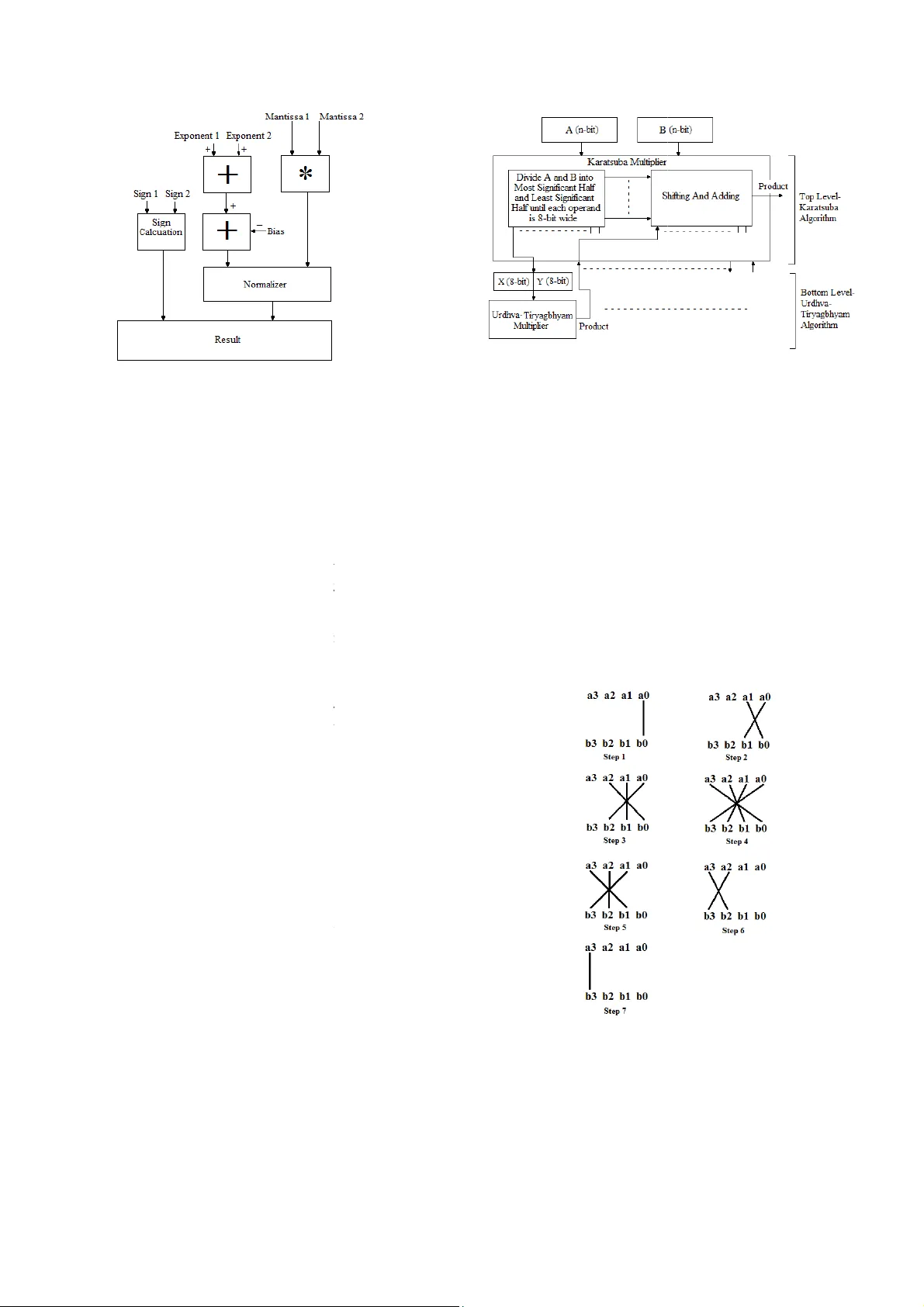
Run-time reconf igurable m ulti-precis ion floating point multip lier design f or high speed, low-power application s Abstract : Floatin g poi nt multi plication is one of the crucial operati ons in m any a pplicatio n domai ns such as ima ge proce ssi ng, signal p rocessing etc. But every applicati on requires diffe rent working feat ures. Som e nee d hi gh pre cision, some ne ed low po wer consumption, l ow latenc y etc. Bu t IEEE-75 4 format is not re ally flexible for the se specificatio ns and als o design is complex. Opti mal run-time r econfig urable har dwar e implem entations m ay need the use of cust om float ing-p oint form ats that do not nece ssarily follow I EEE specified sizes. In t his paper, w e pre sent a run-tim e-reconfi gur able floating p oint multiplie r implemente d on FPGA with cust om floating point format for diffe rent applic a tions. This floati ng poi nt multipli er can hav e 6 modes of oper ations depen ding on the accurac y or applicati on requir ement. W ith the use of optim al desig n with c ustom IPs ( Intellectua l Properties ) , a better implem entation is d one by truncating t he inputs bef ore multiplic ation. And a c ombinati on of Karatsu ba al gorithm a nd Urd hva-Tir yagbhy am al gorithm (Ve dic Mathematics) is used to imple men t unsigned binary multipl ier. This further increases the effic iency of the multiplie r. Keyw ords: f pga, Run-tim e- reconfig urable, Variable -preci sion, Floating p oint multiplie r, Vedic m athema tics, Urdhva-Tirya gbhyam , Kara tsuba I. I NTRODUCTION Floating point multiplicatio n units are essential Inte llectual Properties (IP) for m odern multim edia and high perf ormance computing such as graphics acceleration, signal processing, image processi ng etc. There are lot of effort is made over the past few decades to improve perform ance of floating point comp utatio ns. Flo atin g poi nt uni ts are not o nly co mple x, but also require m ore area and hence more power consum ing as compared to fix ed point multipliers. And the complexity of the floating point unit increases as accuracy becom es a maj or issue. Even a minute error in accu racy can cause m ajor consequences . These errors are possible in floating poin t units mainly becau se of the discrete behavior of the IEEE- 754 [1] floating point repres entation, where f ixed num ber of bits is used to represent numbers. Due to the high computational requirements of scie ntific applications s uch as computational geometry, climate modeling, computational physics, etc., it is necessary to have extreme precision in floating point calculations. And these in creased precision may not be provided w ith si ngle precis ion or double p recision f ormat. That further increas es the complexity of the unit. But some application s do not requ ire high precisi on. Even an approximate value will be sufficient for the correct operation. For applications wh ich require lower precision, the us e of double precis ion or quadru ple precisi on floating point units will b e a luxur y. It wast es ar ea, po wer and a lso incr eases latency. For devices such as portable or w earable dev ices in which accuracy requ irement varies with different applications and also power con sumpt ion is a very import ant factor, u se of high precision floating poi nt multipli ers is not a g ood option . In such cases a variable precision multiplier will be a good option which can save muc h power and time when applicati on doesn’ t need high precision. There are a lot of such models like [2], [3] an d [4]. Most of su ch designs m ake use of already available IPs such as DSP (Digital Signal Processi ng) units and 18x18 m ulti plier un its. In thi s proposed paper, w e present a power efficient design of floating point multip lier with different m odes of accuracy selection. With differen t precision modes, we can sel ect the mode whi ch is appropriate for the concerned application . As accurac y requirement decreases, the width of mu ltiplier decreases and hence the power consumption and latenc y. II. P ROPOSED MODEL The proposed m odel is a recon figurable multi-precis ion floatin g point mu ltiplier whi ch can be operated in six diff erent modes accordin g to the accuracy requiremen ts. It can perform floating point for mat multiplication of d ifferent mantissa si zes depending on the precision requirem ent. The basic un it is a Double-precision floating point unit. According to the precision selected, the size of the mantissa is varied. Fig. 1 shows the floating-poi nt multiplication format used in the proposed m odel. The multiplier accepts two inpu ts each of 67-bit wide. Th e first 3 bits are used for mode selectio n. The inputs to the multiplier can be given in double-precision floating poi nt format with first 3 bits (66 th bit to 64 th bit) as mode select bits. R.K.Sharma School of VLSI Design an d Embedded Sys tems National Institute of Technolo gy Kurukshetra Kuru kshetr a, I ndia rksharama@nitkk r.ac.in Arish S School of VLSI design and Em bedded Systems National Institute of Technolo gy Kurukshetra Kuru kshetr a, I ndia arishsu@gm ail.com Cite as: S. Arish and R. K. Sharma, "Run-time reconfigurable multi-precision floating point multiplier design for high speed, low-power applications," 2015 2nd International Conference on Signal Processing and Integrated Networks (SPIN), Noida, 2015, pp. 902-907. doi: 10.1109/SPIN.2015.7095315 The value of th e mode select bits for both t the same, otherwise a m ode select err o generated and the execution w ill be stop p mode s elect bit com binations f or diff erent m table 1. The diff erent modes in the propos ed multi- pr are the following. Mode 1: Mode 1 is au to mode, i.e. the co select th e optimum mode by analy z ing th e i n execution. The optimum mode is selecte d number of zeroes after a leading 1. If the nu m or more after a leadi ng 1, then the bits up t o counted. If the number of bits up to that lea d 8, then mode 2 or 8- b it m antissa mode will number of bits before the le ading 1 is le s mantissa mode will be selected and so on. Mode 2: This is a custom precisi on form a double- p recision floating point multiplier w i of 8- bit. Mode 3: This is a custom precisi on form a double- p recision floating point multiplier w i of 16- bit. Mode 4: This is a custom precisi on form a double- p recision floating point multiplier w i of 23- bit. Mode 5: This is a custom precisi on form a double- p recision floating point multiplier w i of 36- bit. Mode 6: This mode is a fu lly fledged dou ble point multiplier at the cost of accuracy. The modes wi th less num ber of m antissa b amount of power. These modes are best multiplication and al so for applications wh e a big i ssue. Ro undi ng of bits is do ne b efore every mode except mode 6 and th is reduces result s. A simple block diag ram of the proposed m fig. 2. The cus tom precision formats with 8 16- b it manti ssa are best su ited for inte g where fractional accuracy is not an is sue. I t 3 1 11 52 Mode Sign Ex ponent Mant i select Fig. 1 Fl oating point for mat used in t h e pr o p TABLE I - Different modes Mode Mode sele c Mode 1(Au to Mode) Mode 2 Mode 3 Mode 4 Mode 5 Mode 6 000 001 010 011 100 101 t he in puts must be o r signal will be p ed. The different m odes is s hown in r ecision multiplier ntroller itself will n puts and will star t d by co unt ing t he m ber of zeroes is 6 o that leading 1 is d ing 1 is le ss than be selected. If the s s th an 16, 16-bit a t. It u ses a ba si c i th a mant issa siz e a t. It u ses a ba si c i th a mant issa siz e a t. It u ses a ba si c i th a mant issa siz e a t. It u ses a ba si c i th a mant issa siz e -pre cisio n float ing b its consum es less suited for integer e re accuracy is not multiplication for huge varia tio ns in m odel is sho wn in 8 -bit mantissa and er multiplicatio ns t can also be used for low value fractional m u integer value as result. B y us i instead of a fully-fledged d o multiplier can save a lot o f po w The binary unsi gned m u multiplicatio n is implemente d Karatsuba algorithm [4, 5] algor ithm, which gi ves bette r and area. III. F LO AT IN G P O A floating point number is r [1] as or p erform multiplication of t wo and 2 , the sig n multiplied to get t he produ c added to get t he product expo n 2 . The hardware multiplier is sho wn in fig. 3. The importan t blocks in th e floating point multiplier is des c A. Sign Calculati on The MSB of float ing point The sign of the produ ct will b are of same sign and will b opposite s ign. So, to obtai n th e a simple XOR gate as the sig n B. Addition of Expo nents To get the product expon en t toget her. S ince we use a bi a exponen t, we need to subtr a exponents to g et the actual e 127 ( 01111111 ) for s 1023 ( 0111111111 ) for p ropo sed custo m preci sion fo r The computational tim e of ma n much m ore than the expone n carry adder an d ripple bor r exponent addition. Fig. 2 Bl ock dia gra m i ssa p osed m odel c t bits u ltiplication which require an i ng 8-bi t and 16-bi t multipl iers o uble precis ion float ing point w er and can increase the s peed. u ltiplier used for mantissa d by using a combination of and Urdh va-Tiry agbhyam [6] optimization in ter ms of speed O INT M ULTIP LIER r epresented i n IEEE-754 format [7]. To float ing p oint number s 1 n ificant or mantissa parts ar e c t mantissa and ex ponents are n ent. i.e.; the product is 1 block diag ram of f loatin g point e implemen ta tion of proposed c ribed belo w [8]. number represents the sign bit. b e positiv e if both the num b ers b e negat ive if nu mber s are of e sign of t he product, we can use calculator. t , the input exponents are added a s in the float ing point f ormat a ct the bias from the sum of e xponent. The v alue o f bias is s ingle precision format and double precis ion form at. In r mat als o, a bias of 127 is used. n tissa multiplicatio n operation is n t addition. So a si mple ripple r ow subtracter is optimal for m of the propo sed m odel C. K aratsuba-Ur dhva Tiry agbhyam binar y m In floating point multiplication, mo s complex part is the mantissa multiplicati o operatio n requires more time compared to a d number of bits increase, it consumes m ore double precis ion format , we need a 53x53 b i singl e precision format we need 24x 24 requires mu ch time to perform thes e opera t major contrib utor to the dela y of the floatin g To make the multiplication o peration more fast er, the proposed model us es a combin a algo rithm a nd U rdhva Tir yagb hyam al gor ith m Karatsuba algorithm uses a div ide and where it breaks dow n the inputs in to Most S Least Significant half and this proces s c o operands are of 8- b its wide. Karatsuba algo r for operands of higher bit length. But at l o w not as efficient as it is at higher bit lengths . problem , Urdhva Tiryagbhy am algorithm is stage s. T he mod el o f Urd hva-T ir yagbh y shown in Fig. 4. Urdhv a Tiryagbhy am alg o algorithm for b inary multiplic ation in terms But as the number of bits incr eases, delay al s p artial products are added in a ripple m anne r 4- b it multiplicatio n, it requir es 6 adders co n manner. And 8-bit multi p lication requires 1 4 Compensating the dela y will cause incr e Urd hva Ti ryagb hyam a lgori thm i s not t h number of bits is much m ore. If we use Kar a higher s tages and Urdh va Tiryagbhyam a l stages, it can so m ewhat co mpensate the lim i algorithms and hence the multiplier beco m The circuit is further opti mized by us ing car r save adders inst ead of ripple carry adders. delay to a great extent with minimal incr e These two alg orithms are explained in d e sections. Fig. 3 Floa ting po int multi plier m ultiplie r s t important and o n. Multiplica tion d dition. And as the area and time. In i t multiplier a nd in bit multiplier. It t ions and it i s the g point multipli er. area efficient and a tion of Karats uba m . conquer approa ch igni fica nt hal f and o ntinue s until the r ithm is best sui ted w er bi t len gth s, it is . To eli minate this used at the lower y am al go rith m i s o rith m is the best of area and delay. s o increases as the r . For example, for n nected in a ripple 4 adders and so on. e ase in area. So h at o ptim al if the a tsuba algorithm at l gori thm a t lo wer i tations in bot h the m es more eff icient. r y s elect and carry This reduces the e ase in h ardware. e tail in the belo w Urdhva Ti ryagbhyam algorith m Urd hva-T iryagb hya m sutr a i method for multiplication [ applicable to all cases of mu l t short and consists of only o n ‘Vertically and crossw ise’. In U the number of s teps required f o and hen ce the speed of multipl i An illustration o f steps for c bit numbers is shown b elo w a 3 a 2 a 1 a 0 and b 3 b 2 b 1 b 0 and p roduct. A nd the temporary pa r The partial pr oducts are obtai n The line notation of the step s i s Step1: t 0 1 a 0 b 0 . Step2: t 1 2 a 1 b 0 a Step3: t 2 2 a 2 b 0 a Fig. 4 Ka ratsuba-U r d Fig. 5 L ine notati on of U r m for multiplica tion i s an ancient Vedic mathema t ics [ 6]. It is a gene ral for mula t iplication. The formula is very n e compound word and means U rdhva Tir yagb hyam a lgor ithm, o r multiplication can be r educed i cation is increased. c omput ing the product of tw o 4- w [9, 10]. The tw o input are le t p 7 p 6 p 5 p 4 p 3 p 2 p 1 p 0 be the r tial products are t 0 ,t 1 ,t 2 ,…,t 6 . n ed from the steps given below. s shown in f ig. 5. a 0 b 1 . a 1 b 1 a 0 b 2 d hva m u ltiplie r mode l r dhva T iryagb hya m sutr a Step4: t 3 3 a 3 b 0 a 2 b 1 a 1 b 2 Step5: t 4 2 a 3 b 1 a 2 b 2 a 1 b 3 . Step6: t 5 2 a 3 b 2 a 2 b 3 . Step7: t 6 1 a 3 b 3 The product is obtain ed by adding s 1 ,s 2 below, wh ere s 1 ,s 2 s 3 are the partial su m s 1 t 6 t 5 0 t 4 0 t 3 0 t 2 0 t 1 0 t 0 s 2 t 5 1 t 4 1 t 3 1 t 2 1 t 1 1 s 3 t 3 2 Pr oduct t 6 t 5 0 t 4 0 t 3 0 t 2 0 t 1 0 t 5 1 t 4 1 t 3 1 t 2 1 t 1 1 t 3 2 0 0 0 p 7 p 6 p 5 p 4 p 3 p 2 p 1 This m ethod can be furth er optimized t o re d hardware. A m ore optimized hardw are arch i shown in Fi g. 6. T his mod el a ctuall y help need for th ree operand 7- b it adder and hen c e and delay. The adders are c onnected in rippl e The expression s for product bi ts are as sh ow n p 0 a 0 b 0 Fig. 6 Hardware architecture for 4 x4 U Tiry agbhyam m ultiplier. a 0 b 3 . s 3 as sh own m obtained. t 0 + 0 + 0 p 0 d uce the num ber of i tecture [11, 12] is s to eliminate the e reduces hardware e manner . n below. p 1 1 a 1 b 0 a 0 b 1 p 2 2 MSBADDER1 p 3 3 MSBADDER 2 p 4 4 M SBADDE R p 5 5 M SBAD D p 6 6 M S B p 7 Since there are more than tw o can use carry save addition to technique redu ces the delay to ripple carry adder. K aratsuba Al gorithm for m Karatsuba multiplicatio n al g multiplying very large numbe r Anatoli Karatsuba in 1962. It i in w hich we di vide the num b half and Least Significant h p erform ed. Karatsuba algori multipliers req uired by replac i addition operations . Additi o n multiplications and hence the s As th e number of bit s of inpu t b ecomes more efficient. This a inpu ts is more than 16 bits. Kar atsuba algor ith m is sho wn i Karatsuba algorithm for two i n as follow. Pr oduct . X and Y can be w ritten as, 2 / 2 / U rdhva Fig. 7 Bl ock dia gra m 1 2 a 2 b 0 a 1 b 1 a 0 b 2 3 a 3 b 0 a 2 b 1 a 1 b 2 a 0 b 3 4 R 1a 3 b 1 a 2 b 2 a 1 b 3 5 D ER1a 3 b 2 a 2 b 3 6 ADDER1a 3 b 3 o operands in adders 2 t o 5, w e im plement adders 2 t o 5. This a great extend co m pared to the ultiplicatio n g orithm [4, 5] i s best suit ed for r s. This meth od is dis covered by i s a divi de and conqu er method, b ers into their Most Significa n t h alf and then multiplication is thm reduces the number of i ng multiplication oper ations by n s operations are f aster than s peed of multiplier is increase d. t s increase, Karatsuba algorithm a lgorit hm is optimal if widt h of The hardware architecture of in Fig. 7. n puts X and Y can be explained . X l X r (1) . Y l Y r (2) m of Karatsuba m ultiplier Where X l, Y l and X r , Y r are the Most Signi ficant half and Least Significant half of X a nd Y respectively, and n is the number of bits. The n, . 2 . X l X r . 2 . Y l Y r 2 . X l Y l 2 / X l Y r X r Y l X r Y r (3) The Second term in equ ation (3 ) can be optimized to redu ce the number of multiplication operatio ns. i.e.; X l Y r X r Y l X l X r Y l Y r X l Y l X r Y r (4) The equation (3) can be re-w ritten as, . 2 . X l Y l X r Y r 2 X l X r Y l Y r X l Y l X r Y r (5) The recurrence of Karats uba algorithm is, 3 . (6) D. Normalization o f the result Floatin g point repres entations have a hidden bit in the mantissa, which al ways has a value 1 and hence it is not stored in the memor y to save one bit. A lead ing 1 in the mantissa is considered to be the hidden bit, i.e. the 1 just i mmediate to the left of decim al point . Usually normal ization is done by shifting, so that the MSB of mantissa becomes nonzero and in radix 2, non zero means 1. The decim al point in the mantissa multiplication result i s shifted left if the lead ing 1 is not at t he immediate left of decimal point. An d for each left shift operation of the resul t, the exponen t value is increm ented by one. This is called normalization of the resu lt. Since the value of hidden bit is always 1, it is called ‘hidden 1’. E. Representation of exceptions Som e of the numbers cannot be represented with a normalized significand. To represen t those numbers a special code is ass igned to it . In the propos ed model , we use fou r output s ignals name ly Zero, In finity, NaN (Not-a-num ber) and Denormal to represen t these exceptions. If the produ ct has 0 and 0 , th en the result is tak en as Zero (±0). If t he product has 255 and 0 , then the result is taken a s Infinity ( ∞ ). If the pr oduct has 255 and 0 , then the result is taken as NaN. Denor malized values or Denormals are numbers without a hidden 1 and with the smal lest possible exponent. Denormals are us ed to represent certain small numbers that cannot be represented as normalized numbers. If the product has 0 and 0 , then the resu lt is represented as Denorm al. Denaormal is represented as 0. s 2 , wh ere s is the si gnific and . IV. I MPLIMENTATION AND RESULTS T he mai n objective of this work is to design and im ple ment a floating poin t variable-precision circu it such that the device can reconfigu re itself according to the precisi on requirements and can operate at high speed irrespective of accuracy and consume less pow er where accuracy is not an issu e. Since mantissa multiplica tion is the most co m plex part in the floating point multiplier, we designed a multiplier which can operate at high speed and increase in delay and area is significantly less with increasing number of bits. The floating point multipliers of different modes wi th IEEE-754 stan dard format and custom precision format is implemen ted separately using Verilog HDL and tested. The binary multiplier unit (Karatsuba-Urdh va) are further opt imized by replacing s imple adders with effi cient adders like carry select adders and carry save adders . The proposed model is im plemented, synt hesized and sim ulated u sing Xil inx Synth esis Tools (IS E 14.7) targeted on Virtex4 fami ly. The model operates in a selected mode on ly and during operation, on ly the s elected multiplier unit will be in ON state and a ll other multiplier s units will be in OFF state. Hence, if a low precision mode is selected, the area and hence the power consumption will be less. The summary of resu lts is given in table II and table III. Comparison with various multiplier units is given in tables IV, V, VI, VII and VIII. TABLE II - Performance analysis of Karatsuba-Urdhva multipliers in t h e pr oposed m odel 8-bit multiplier 16-bit multiplier 24-bit multiplier 32-bit multiplier Slices 113 410 972 1389 LUTs 120 451 1018 1545 IOBs 33 65 97 129 Delay 9.396ns 11.514ns 12.99 6ns 13.14 1ns (MHz) 274.469 248.964 226.5 08 209.606 Logic levels 14 22 31 39 TABLE III – Perform ance anal ysis of floating point units in the propos ed mode l 8-bit prec ision floati ng point mult iplier 16-bi t prec ision floati ng point mult iplier 23-bi t prec ision floati ng point mult iplier Doubl e prec ision floati ng point mult iplier Slices 157 475 977 3877 LUTs 220 584 1073 4033 IOBs 61 83 104 193 Delay 12.254ns 14.577ns 16.39 2ns 18.96 6ns (MHz) 264.767 240.955 226.508 173.9 52 V. C ONCLUSION AND FUTURE WORK This paper des cribes a method to ef fectively adjust the delay and pow er consumption for different accu rac y requirements. A lso the paper shows how to effectively reduce the percentage increase in delay and area of a floating point multiplier with increase in n umber of bits by using a very efficient combination of Karatsuba and Urdhva-Tiryagbhy am algorithms. The model can be further optimized in terms of delay by using pipelin ing methods an d precision of th e result can be increased by adding efficient truncation an d rounding methods . R EFERENCES [1] IEEE 754-2 008, I EEE Standard for F loating-Point A rithmetic, 20 08. [2] K. Mano lo poulo s, D. Reisis , V.A . Cho uliaras, “ An Ef ficien t Mul tiple Precision F loating-Point Mul tiplie r”, 18th I EEE Internatio n al Con ferenc e on Elect ronic s, Circu its and Syst ems ( I CEC S), pp. 153-156 , 2011 [3] Claud io Brun elli, Pert tu Sa lmela, J armo Taka la and Ja ri Nurmi , “A Flexible Multiplier fo r Media Processing” , IEEE wor kshop on Signal proc essin g System Design and I mple ment ation, pp. 70-74, 2005 [4] N.Anane, H.Bessal ah, M.I ssad, K.Messaou di, “Hardware imple menta tion of V ariable Precisio n Multipl ica tion on F PGA”, 4th Interna tiona l Conferen ce on Des ign & Tech nolog y of Integra ted Systems i n Nan oscale Era, pp. 77-81, 2009 [5] Anand Me hta, C. B. Bidh ul, Sajeev an Jose ph, Jayakris hnan. P, “Im pleme ntation o f Sing le Pre cision F loating Po int Mul tiplie r us ing Karatsu ba Algorith m”, 2013 Inte rnati onal Conf erence on Green Compu ting, Com munication and Conserva tion of Energy (IC GCE), pp. 254 -256, 20 13 [6] “Ve dic mathe matics ”, Sw ami Sri Bharat i Krsna Thir thaji Mahar aja, Moti lal Banara sidass Indologi cal p ublish ers and Book s ellers, 1965 [7] Comp uter A rithmetic, Behro oz Parha mi, Oxf ord U niversity Press, 20 00. [8] B. Jeev an , S. N arende r , C.V . K rishna Re ddy , K. S ivani, “A High Speed Bina ry Floatin g Point Mult iplier Using Da dda Algorit hm”, Intern ationa l Multi -Conferen ce on Aut omation, Comput ing, C ommunic ation, C ontrol and Com pres sed Sens ing, p p. 455- 460, 2 013 [9] Poornima M, Shi varaj Kumar Pa til, Shi vukumar , Shridhar K P , Sa njay H, “I mplementatio n of Multi p lie r usi ng Ve dic Al gor ithm”, I nternational Jour nal of Inno vativ e T echnol ogy and E xplo ring Enginee ring (I JIT EE), ISSN: 22 78-307 5, Volume-2 , Issue-6, pp. 219 -223, May 2013 [10] R. Sride vi, Anir udh Pal akurt hi, A khila Sadh ula, Hafs a Mahr ee n, “Desig n of a Hi gh Sp eed Mu ltiplier (Anc ient Ved ic Ma themati cs Approac h)”, Intern ati onal Journa l of Engin eering Res earch (ISSN : 2319-68 90), Volu me No.2, Issue No.3 , pp : 183-186 , July 20 13 [11] Har pree t Singh D hill on, Abhijit M itra, “ A Reduced-B it Multipli cation Alg orithm fo r Dig ital A rithmetic ”, Wor ld Acade my of S cience , Engi neer ing a nd Te chnology , Vol 19, p p. 7 19-72 4, 20 08 [12] Premananda B.S., Samarth S. Pai, Sha shank B., Shashank S. Bhat, “De sign and I mpleme ntation o f 8-Bit Ve dic Mul tipl ier”, I nternation al Journ al of Adva nced Researc h in E lectri cal, E lectron ics and Instr ument ation E nginee ring, Vo l. 2, Issue 12, pp . 5877- 5882, De cembe r 2013 [13] R. Sa i Siva Te ja, A. Madhus udhan, “F PGA Im pleme ntation o f L ow- Area Floa tin g Point Multipli er Using Vedi c Mathem atics”, Internat ional Jour nal of Emer ging T echnol ogy and A dvanced E ngine ering, I SSN 2250- 2459, Volume 3, I ssue 12, pp . 362- 366, De cembe r 201 3. [14] Jag adeshw ar Rao M , Sanj ay Dubey , “A Hig h Spee d and A rea Eff icient Booth Recoded Wallace Tr ee Mult ipli er for fast Arit hmet ic Circ uits”, 2012 A sia Pacific Confe rence on Postg raduate Rese arch in Microel ectron ics & Elect ronic s (PRIMEASIA), pp. 220-223, 2012. [15] R.K. Bathija, R.S. Meena, S. Sarkar, Raj esh Sahu, “Low Power High Speed 16x1 6 bit Mu ltiplier u sing Ved ic Ma themat ics”, Internat iona l Jour nal of Compu ter A pplicatio ns (0975 – 8887), Vo lume 59– No .6, pp. 41-44 , Dece mber 2012 [16] Anna J ain, Bai sakhy Dash , Ajit K uma r Pand a, Much harla Su resh, “FPG A De sign of a Fast 32- bit F loating Poin t Multi plie r Unit ”, Inte rnational Conf ere nce on D evice s, Circui ts and S yste ms (I CDCS), pp . 545 -547, 20 12 TABLE IV - Delay co m parison of va rious 8-bit m ultipliers w ith proposed Karatsu ba-Urdhva m ultiplier Ref [9] Ref [12] Ref [13] Proposed multiplier Widt h 8-bit 8-bit 8- bit 8-bit Delay 28.27ns 15.05 0ns 23.973ns 9.396ns TABLE V - Delay co m parison of va rious 16-bit m ultipliers with proposed Karatsu ba-Urdhva m ultiplier Ref [14]-vedic multiplier Ref [15] Propos ed multiplier Widt h 16-bit 16-bit 16-bit Delay 13.452ns 27.148ns 11.514n s TABLE VI - Dela y and a rea comparison of 24- bit multiplie rs with propose d Karatsuba-Urdhv a multiplie r Sli ces LUTs Dela y Ref [16] 1306 2329 16.316ns Propos ed multiplier 972 1018 12.996ns TABLE VII - Delay and area com parison of 32-b it multipliers with propose d Karatsuba-Urdhv a multiplie r LUTs Dela y Ref [14]- Modif ied Bo oth mult iplier (R adix-8 ) 2721 12.081n s Ref [14]- Modif ied Bo oth mult iplier (R adix-16 ) 7161 11.564n s Ref [14] 2704 9.536ns Proposed m u ltiplie r 1545 13.141n s TABLE VIII - Delay and area comparison of SP-floating point multiplier w ith proposed SP FP m ultiplier Sli ces LUTs Dela y Ref [16] 1269 2270 18.783ns Ref [8] 1149 1146 -- Propos ed multiplier 976 1091 16.392ns
Original Paper
Loading high-quality paper...
Comments & Academic Discussion
Loading comments...
Leave a Comment