A Linear LMP Model for Active and Reactive Power with Power Loss
Pricing the reactive power is more necessary than ever before because of the increasing challenge of renewable energy integration on reactive power balance and voltage control. However, reactive power price is hard to be efficiently calculated becaus…
Authors: ** Yanghao Yu, Qingchun Hou, Yi Ge
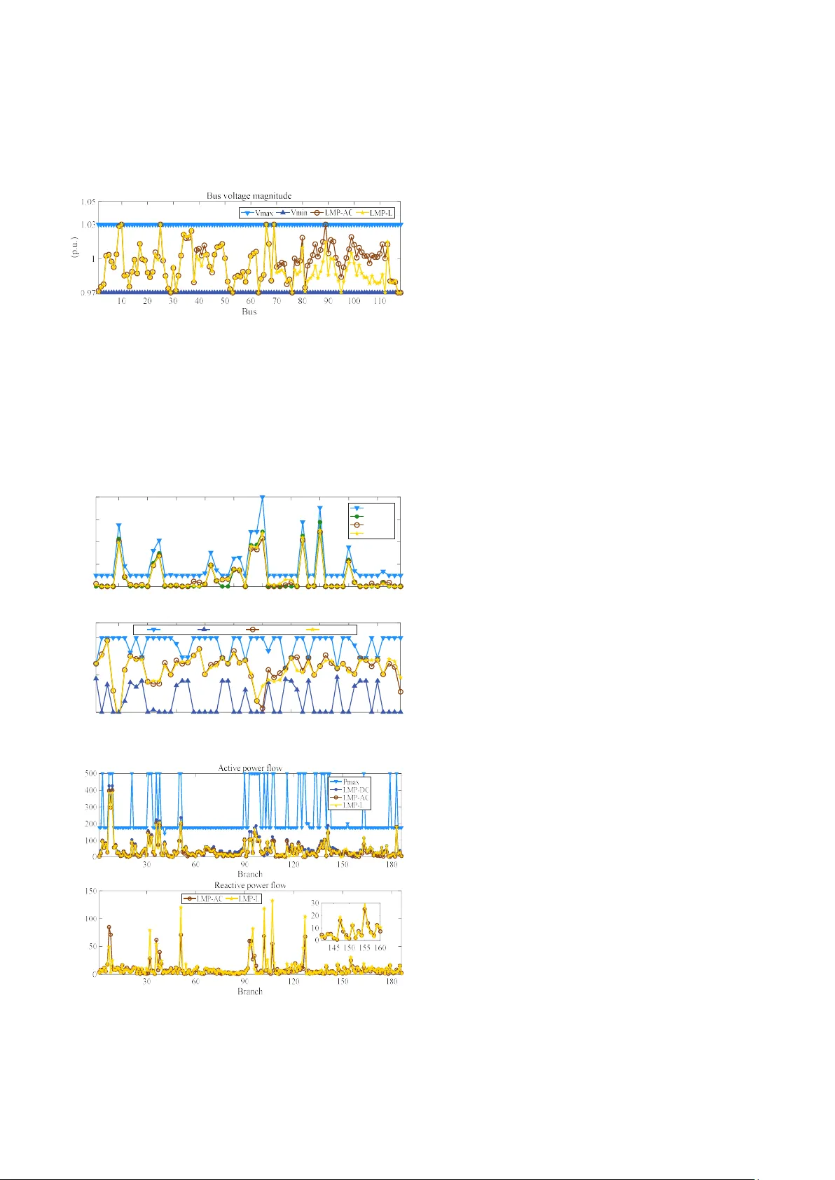
1 A Linear LMP Model f or Active an d R eactive Power with Power Loss Yanghao Yu, Qingch un Hou, Student Me mber, IEEE , Yi G e, Guojing Liu, and Ning Zhang, Senior Me mber, IEEE Abstract — Pricing the reactive power is more n ecessary than ever b efore bec ause of the increasing challenge of renewabl e energy integration on reactive pow er balance and voltage control. However, react ive pow er price is ha rd to be efficientl y cal cul ated because of the non-line ar nature of optim al AC p ower f low equation. This paper proposes a li near model to calculate acti ve and reactive pow er LMP si multaneously consid ering pow er loss. Firstly, a l ineariz e d AC power flow equation is p roposed based on an augmented Gene r atio n Shift Distribut i on Factors (GSD F ) matrix. Second ly, a linearized LMP model is derived using GSDF and loss factors. The f ormulation of LMP is furt her d ecomposed into four components: energy, co ngestion, voltage limitation and power loss. Finally, an iterate algorithm is proposed for calculating LMP with the pro posed model. The performance of the proposed model is validated by the IEEE-118 bus system. Index Terms — Reactive power pricing, optimal pow er flow, Generation Shift Distribution Factor, LMP, power loss. N OMENCLATU RE P , Q Vectors of bus injected active and reactive power , i i P Q Injected active and reactive power at bus i j Y = G + B Admittance matrix of the power system j Y = G + B Admittance matrix without shunt elements ij ij ij Y G jB Element in the i th row and j th column of Y ij ij Y G jB Element in the i th row and j th column of Y V , θ Vectors of Ma g nitud es and phase an g les of bus voltages , i i V Voltage magnitude and phase angle at bus i , M N The number of branches and buses ij ij ij y g jb Admittance of branch ( , ) i j ii ii ii y g jb Shunt admittance at bus i , , l l l m m m P Q I Power flow and current through branch m , G D i i P P The active power generation and active load at bu s i , G D i i Q Q The reactive power gen e ration and reactive lo ad at bus i This work w as supported by the Major Smart G rid Joint Project of National Natural Science Foundation of Chin a and State Grid (No. U17 66212) and Scientific & t echnical project of State Grid "Res earch and application of large-scale ene rgy storage pl anning for receiving- end power sy stem" (No . 5102- 20 19 18309A-0- 0-00). Y. Yu , Q . Hou, N . Zhan g are with the State Ke y Lab of P ower Systems, Departm ent of E lectrical Engineering, Tsinghua University , Beijing 100084, China (e-m all: ningzhang@tsinghua.ed u.cn ). Y. Ge, G. Liu a re with E conomi cs a nd Te chnol ogical Res earch I nstitute, State G rid Jiangsu Electric Po wer Co., Ltd., Nanji ng, China. , P Q i i F F The fictional nodal demand at bus i , Loss Loss P Q Total power loss of the system , P Q i i LF LF The active and reactive power loss factor at bus i , P Q i i DF DF The active and reactive power d e livery factor at bus i I. I NTRODUC TION OCATIONAL Ma rginal Price ( LMP) is defined as the marginal expenses of both generat ors and transmissi on system to suppl y the in crement of active pow er at each b us. A pow er market usin g L MP can p rovide the right p r ice si g nal to relieve the congestion of p ower system. T herefore, LMP has been widel y ad opted i n Indepen dent S y stem Operators (ISOs), such as PJM int erconnection, the New York market , and the New England ISO [1]. The LMP can be di vided i nto active powe r LMP (ALMP) and reacti ve power LMP (RLMP). The l ater denot es marginal cost to supply t he incr ement of reactive p ower d emand at each bus. Currently the LMP ad opted by all of the po wer market i s ALMP onl y . Most re active power sources like stati c VAR com pensators (SVCs) and switched capacitors ( SCs) are n ot pri ced by RLMP but compensated as ancillar y servic e i n power market. Nowada y s, i ncreasing ren ewable energy penet ration brin gs g reat challenge to power system voltage securit y . The adequate reactive pow er supply ma y become crit ical. Sinc e the reactive power cannot be transmitt ed by long dist ance and i s usuall y locall y b alanced, the need of r eactive power for different node would be distinct. The val ue of providing reactive power would be different even there is no congestions in t he power system. T herefore, intro ducing RLMP in the market woul d provi de significant p rice signal fo r both shor t-term operation and l ong-term plannin g. The value of LMP can be decompose d into s everal com ponents. Referen ce [ 1] prop oses the DCOP F model with loss to d ecompose LMP into th e cost s of marginal energy, margin al loss and congestion. Reference [2] i ntroduc e s the concept of LMP to a distribution system. The distributi on LMP (DLMP) is decom p osed i nto margin al energy c ost, l oss cost and conge stion c omponents. Reference s [3 ], [4 ] further anal y zes both ac ti ve and reactive power D L MP w ith consi deration of congesti on and voltage suppo rt. The DLMP i s divid ed into five compon ents: marginal costs for active power, reactive po wer, congest ion, vol tage s upport, and powe r loss. The value of different LMP c omponents togeth er r eveal the econo mic and oper ation condition s of power system, whic h provi de price signal t o influence the beh avior of participants t o miti gate t ransmission congestion and s timulate reacti ve p ower L 2 supply for volt age support. LMP can be d erived f rom optimal power flow (OPF) [ 1]. In practi cal application of LMP, AC opt imal power flow (ACOPF) and DC optimal power flow (DCOPF) are two cl assic models. ACOPF can s imult a neousl y calc ulate ALMP and RLMP accuratel y . But it is a no n-convex prob lem which may be computatio nally int ractable even for s maller sy ste ms [5]. Addition a lly, LMP derived from ACOPF are not a nalytical so that it can no t be dec omposed into differ ent c ompone nts and is lack o f transpare ncy [ 6]. Comp aratively, DCOPF m odel is more conci se and efficient , wh ich m akes it wi dely utili zed by LMP-based mar kets. However, since it neglect s the voltage fluctuation and p ower l o ss, it has a relativel y low acc urac y i n LMP calculatio n. In a ddition, DCOPF cannot calc u late RLMP since it i gnores t he reactive power balan ce and reactive power flow. Recent researches have been condu cted to improve th e L MP calculatio n. Referen ce [7] uses en ergy ref erence b us independe n t model t o o btain a more accurate ca lculation on energy, conges tion and l oss components o f LMP. In Refer ence [8], an it erative DCOPF algorit hm is propos ed to address the nonlinear marginal loss. Reference [9] proposes a linear loss-em bedded mo del t o calcul ate LMP with l oss compon ents by deal ing wit h margi nal generator s under lossless DCOPF solutio n . Reference [10] pr oposes a line ar-constrained and convergence-guara nteed OPF mo del that explicitly con siders the c onstraints of react ive power b alance and bus voltage. Reference [ 11] proposes a lineari zed power flow model with decouplin g of volt age magnitu de and phase an gle to ac hieve accurate estimatio n of voltage magni tude. Base d on t he lineariz ed power flow mod e l, Refere nce [6] f urther proposes the d ecoupled OP F model using Generation Shift Distributio n Factors (GSDF) and furth er applies it to jointly cal culate ALMP and RLMP wi th r espect to volt age con straints, b ut the impact of network loss is neglecte d in this model. This paper proposes a linearized iterati ve mod e l t o calculat e both ALMP and RLMP considering power loss. A l inearized AC po wer fl ow e quation is proposed base d on the augmented GSDF matri x. T he active and reactive power loss are linearized by introd ucing l oss f actor (LF). An iterat e a lgorithm is propose d to calculate power l oss and th e LMP . Finally, the accurac y a nd perfor mance of the pro posed m odel is validated on an IEEE-118 bu s case. The rest o f thi s paper i s organized as follows: Secti on I I constructs the linear ized LMP mo del. Sectio n III validat es the accurac y of the A L MP and RLMP cal culation of the model through the IEEE 1 18-bus case on MATPOWER. Finally, Section I V concludes the pa per. II. L I NEARIZED LMP M ODEL W ITH P OWER L OS S This Section builds the LMP mo del b ased on GSDF. Th e modeling is di vided into five s ubproblems: 1) Introducing GSDF-based linear AC power flow model; 2 ) Lin earizing the power losses; 3) Buil ding GSDF - based LMP mod el; 4) Derivi ng ALMP and RLMP ba sed on the LMP model; 5) Proposing iterate al gorithm to solve L MP. This Section wil l present th e tec hnical details of each subproblem. A. Power Fl ow Equations w ith GSDF A lineari zed powe r flow e quation with respect to volta g e magnitu de and p hase a ngle is prop osed b y ref erence [11] as follow s. - P B -G θ θ = - C Q G B V V (1) The ma trix C in Eq. ( 1) is a 2 2 N N matrix det ermined solel y by the element of admitta nce matrix. Based on Eq. (1), the active p ower b alance e quation is der ived as follows: 1 1 1 1 1 1 1 1 1 1 1 0 N N N N N N N N N i ij j ij j ij j ij j i i j i j j i j i N N jj j jj j j P G V B G V B g V g (2) The two appr ox imation ste ps in Eq. (2) are ba sed on t he ass umpt ions t hat 1 j V and 0 jj g . Similarl y , we have the reactive power balance equat ion as follo ws: 1 1 1 N N N i jj j jj i j j Q b V b (3) Acco rding to Eq. (2 ), the eq uations Eq . ( 1) is not inde pendent. I n other wor ds, matrix C in (1) i s close to singul ar. So we remove the row a nd co lumn of t he re ference bus in C and invers e the ne w 2 1 2 1 N N matri x. We then f ill the row and c olumn of th e reference bus i n the i nversed matri x wit h zeros. Hence, we have a new 2 2 N N matrix X satisf ying: θ P X V Q (4) Unfoldin g the matrix form of E q. (4), th e voltage equation is acqui red as follows: , , 1 1 N N i N i k k N i N k k k k V X P X Q (5) Acco rding to Eq. ( 4), t he p ower flow o f b ranches can be linea rly express ed by t he bus power injection both of ac tive and reactive parts: , , , , 1 , , , , 1 = = l m ij i j ij ij i j N ij N i k N j k ij i k j k k k N ij N i N k N j N k ij i N k j N k k k P P V V g b g X X b X X P g X X b X X Q (6) , , , , 1 , , , , 1 = l m ij i j i j ij i j N ij i k j k i j N i k N j k k k N ij i N k j N k ij N i N k N j N k k k Q Q b V V g g X X b X X P g X X b X X Q (7) The coefficients of k P and k Q in Eqs. (6) -(7) forms t he GSDF m atrix between the b ranch po wer flow and power inj ec tio n: 3 , , , , , , , , , , , , , , , , P P m k ij N i k N j k ij i k j k P Q m k ij N i N k N j N k ij i N k j N k Q P m k ij i k j k ij N i k N j k Q Q m k ij i N k j N k ij N i N k N j N k GSF g X X b X X GSF g X X b X X GSF g X X b X X GSF g X X b X X (8) Finall y , t he active a nd reactive power flow equations (Eqs. (6)-(7)) can be expressed using GSDF: 1 1 1 1 1 1 1 1 , for = 1 , 2 , for = 1 , 2 N N l P P P Q m m i i m i i i i N N P P G D P Q G D m i i i m i i i i i N N l Q P Q Q m m i i m i i i i N N Q P G D Q Q G D m i i i m i i i i i P GSF P GSF Q GSF P P GS F Q Q m M Q GS F P GSF Q GSF P P GSF Q Q m M (9) Diff erent from classi c DC power flo w model , t he p roposed model consid ers both active and reactive power, which provide foundations for deriving ALMP a nd RL MP. B. Conside ri ng Power Loss in GSDF-bas ed Power Flow Equati ons It should be noted that in the derivation of last subsection we do no t consider power l osses. In other words, th e t otal active power generation and reactive power generation i n E q. (2) equals t he active lo ad and reactive lo ad respectively ( plus the load on th e shunt branch ). Such loss le ss consumpti on does not coincide with practic al power s y stem. Therefore, we need to consid er the po wer losses in p ower bala nce equations a nd allocat e the power losses to e ach node as virtual lo ad. Acco rding to Joule’s Law, b oth acti ve and r eactive po wer losses, can be calculated using branch po wer flow (a ssuming that 1 i V ): 2 2 1 1 2 1 1 1 2 2 1 1 2 1 1 1 M M l l Loss m m m m m m M N N P P G D P Q G D m i i i m i i i m m i i M M l l Loss m m m m m m M N N P P G D P Q G D m i i i m i i i m m i m P I R P R GSF P P GSF Q Q R Q I X P X GSF P P GSF Q Q X (10) In o rder to consider power losses, t he concept of loss factor (LF), delivery factor (D F) an d fictio nal n odal demand (FND) [ 8] are i ntroduced in t his paper . LF indicates t he ma rg inal power losses with re spect t o an incremen tal power injection on a bus, while DF indi cate th e active and reactive p ower th at is equivalentl y inje c te d to t he gri d. LF and DF for act ive a nd reactive p ower can be stated a s Eq. (11). 1 1 = 2 , 1 for = 1 , 2 = 2 , 1 for = 1 , 2 M P l P P P P Loss i m m i m i i G m i M Q l P Q Q Q Loss i m m i m i i G m i P LF P GSF R DF LF i N P Q LF P GSF X D F L F i N Q (1 1 ) It shoul d be noted that P i LF and Q i LF ma y be negat ive for som e node, denoting t hat the power inj ection would reduce the pow er losses. We int r oduc e t he DF into the power balance Eqs. (2)-(3) so that t he power losses c an b e explicit ly formula ted i n the equation: 1 1 1 0 N P G D i i i Loss i N N Q G D i i i Loss jj i j DF P P P DF Q Q Q b (12) FND is introduced to evenly allocate th e loss of each br anch to its t wo end buses, math ematically: 2 2 1 1 , , for = 1 , 2 2 2 P l Q l i m m i m m i m i m F P R F P X i N ( 13) Each bus t akes th e P i F and Q i F on their connected branches as a v irtual injectio n. T herefore, the power injectio n a t each bus is re stated as: for = 1 , 2 for = 1 , 2 G D P i i i i G D Q i i i i P P P F i N Q Q Q F i N (14) By i ntroducing the FND in each bus, the total active power generati on no lo nger equa ls to the active l oad since the generati on need to bal ance the extra virtual i njection. It suggests that bot h the acti ve and reactive power loss es are consi dered in the proposed GSDF -based power flow equations. C. LMP Model Based on GSDF Acco rding to the derivations above, especial ly wit h Eqs. (5), (9), (12), and (14), we draw the GSDF-based LMP model as show n in Eq. (1 5). , , i i i a b c represent t he cost coefficients of generat or at bus i , t he cost functions of active and re act ive pow er gen eration are both qu adratic while re act ive fun ction does not have primary term; , , , P Q k i u v denote t he L agrange multi plier of t he con st raints of acti ve power b alanc e, reactive pow er b alance, power flow c ongesti o n and vol ta ge res pectively; , P Q i i DF DF denote t he DF at bus i ; , Lo ss Loss P Q are th e t otal system a ctive and rea ctive power loss; , P Q i i F F are ac tive and reactive FND at bus i ; lim k P is the active power limits of branc h k ; min max , i i V V denote the minim u m a nd maximum voltage at bus i respecti vely ; min max mi n max , , , G G G G i i i i P P Q Q denot e the active and react i ve power generation li mits at bus i resp ectively. 4 2 2 1 1 1 1 1 1 , , 1 . . 0 , for = 1 , 2 N G G G i i i i i i i N P G D P i i i Loss P i N N Q G D Q i i i Loss jj Q i j N N P P G D P P Q G D Q l m m i i i i m i i i i m m i i N V G D P i N i k k k k N i k Min a P b P c Q s t f DF P P P f DF Q Q Q b g GSF P P F GSF Q Q F P m M u h X P P F X 1 lim lim min max min max min max , for = 1 , 2 , for = 1 , 2 , for = 1 , 2 , for 1 , 2 , for 1 , 2 N G D Q N k k k k i i k l m m m i i i G G G i i i G G G i i i Q Q F V i N P P P m M V V V i N P P P i N Q Q Q i N (15) D. A LMP and RLMP Deco mposition When the optimal solu tio n of the model is reached, LMP can be calcula ted by the Lagrange Functi on: 2 2 1 1 1 N G G G i i i i i i P P Q Q i M N V m m i i m i a P b P c Q f f g h (16 ) ALMP is defined as the marginal cost o f an incr emental change of active power demand at a bus. AL MP at bus i can be calculat ed a s the f irst-ord er part ial derivati ve o f t he Lagrange Function w ith respect to the active po wer load at bus i : 1 1 , 1 1 , 1 1 = = = = i D i V M N j P m P m j D D D m j i i i M N P P P i P m m i j N j i m j M N P P P P m m i j N j i i P m j ALMP P h f g P P P DF GSF X GSF X LF (1 7) Simil arly , RLMP i s d efined as marginal cost of a n incrementa l change o f r eactive powe r demand at a bus. T he calculatio n of RLMP at bus i is: 1 1 , 1 1 , 1 1 i D i V M N Q j m Q m j D D D m j i i i M N Q P Q i Q m m i j N j N i m j M N P Q Q Q m m i j N j N i i Q m j RLMP Q f h g Q Q Q DF GSF X GSF X LF (18) Eqs (17) an d (18) derives t he analy ti cal f orm d iff eren t component s of ALMP and R LMP. The first term of LMP is the energy compone nt derived from th e power balance constrai nts. The second term is the congestio n comp onent which is related to the power f low equations. The t hird term is the volt a ge constraint compon e nt. The la st term is l oss component. If loss is not consid ered in a model, LF is zero . When t he constraints on power flow or voltage magni tudes are active, t heir corre sponding components of L MP are non-zero. E. Solvin g Algorithm An i teration algorithm i s propose d to s olve the LMP model with power l oss, as shown in Fig. 1. First, w e sol ve t he LMP model without power loss. Then t he power loss is calculate d usin g E qs. (10)-(11) and is allocated using Eqs. (14). The LMP model is later upd ated with the calculated DF and FND. After one i teration, we solve the updated LMP m odel and re-cal culate the po wer losses. Wh en t he differ ence of po wer l o sses i n two iteratio ns is smaller than a certain threshold, iteration stops and a final LMP is obtained from the newest LMP model. Figure 1 Flow char t of the iteration algorithm III. C ASE S TUDY In this section, the GSDF- base d LMP mod el is appli ed to an IEEE 118-bus case on MATPOWER 6.0 to validate its 5 accurac y in cal culating A LMP a nd RLMP. The model i s impl emented in Ma tlab R2016a with the solver Gurobi 8.0. The simulation platfo rm is a per sonal compute r with a n Intel Core i7 CP U @2.50GHz and 8GB RAM. The IEEE 1 18-bus t est c ase is from MAT POWE R 6.0 toolbox of MATL AB [12] . Meanw hile, t he original case does not contain l imits on b ranch po wer flo w. The bran ch MV A rating dat a are t aken from I ndex of Data Ill inois I nst itute of Technolog y [ 13]. Moreover, th e cas e does n ot p r ovide cost for reactive power . We add the re active cost function of generators and let i c in Eq . (15) be the same as i b . The LMP res u lts of our model (denot e d as LMP-L) are compare d w ith t he LMP model without l oss (denoted as LMP-O), and t he L MP results derived from ACOPF and DCOPF solver in MATP OWER (denoted as LMP -AC and LMP-DC). The result obtai ned from ACOPF is s et as t he benchm ark re sult t o calculate the accuracy of other res ults. A. ALMP Accura cy Evaluation. Since the ALMP is mostly conc erned i n the market, we compare the accur acy of ALMP obtai ned from t he proposed method and that from result derived from LMP-O and DCOPF, taking ACOPF as t he st andard r esult. The index o f th e average error of ALMP (AEA) is introdu ced as: 1 / N AC AC i i i i ALMP ALMP ALMP AEA N (19) Here AC i AL MP is the ALMP result at bus i from ACOPF. In the ACOPF model, when the volt age c onstraint is active, the voltage component influenc es the LMP. In o rder to demonstrat e t he effe ctiveness of our p roposed mo de l i n consid er ing t he voltage co nstraint, three scenarios with different voltage constraints are carried out in th e case study : 1) Loose voltage constraint: min max 0. 90 , 1. 10 V V ; 2) Normal voltage constraint: m in m ax 0 .9 5 , 1.0 5 V V ; 3) T ight voltage co nstraint: min ma x 0.9 7, 1 .03 V V . Fig.2 shows th e A EA of the l oss-embedded L MP model (ALMP-L), LMP m odel without loss ( ALMP-O) and DCOP F model (ALMP-DC) whe n load level changes i n different voltage constr aint scenarios . ALMP-O per forms almost t he same as ALMP-DC i n lo ose and normal scena r ios and sl ightl y better than ALMP-DC i n tigh t sc enario. This indicat es t hat the lineariz ed model without powe r loss is com parable with DCOPF. In add ition, the ALMP-L res ults outpe rform both ALMP-O an d ALMP -DC i n all sc enarios and under all load levels. A t 0.95 p.u. load level, the AEA of ALMP-DC is ab ove 3% in all sc enarios, while the AEA of ALMP-L i s a round 1.5%. LOPF per forms 50% better than DCOPF. As loa d level rises, AEA o f A LMP-L has a t rend o f inc reasing, b ut it still outperforms DCOPF on AL MP. The results show th at th e propose d lineari ze LMP model with powe r l oss shows better accurac y i n calculatin g A LMP when comparing wi th D COPF, and power loss component pla y s a n important role in ALMP accurac y . Fig ure 2 AEA in t hree voltage scenarios B. ALMP and RLMP Analysi s The case in tight voltage constraint is further a nalyzed. Fig.3 pres ents the A LMP and RLMP at each b us from LMP-L, DCOPF and ACOP F respectivel y ( DCOPF do es not have RLMP) . LMP-L tra cks the fluct uation of ALMP deri v ed f ro m ACOPF at most buses. However, DCOPF gives a fixed ALMP value at all buses, th us it has m a ssive er ror compared with ACOPF. One of the reasons is that DCOPF do es not consider the limit o f bus voltage and reacti ve po wer. In the meanwhil e, the RLMP resul ts from L MP-L mo del is almost th e sa me a s that fro m ACOPF, which indicates that model also performs well in RLMP c alculation. ($/MW) ($/Mvar) Fig ure 3 ALMP and RL MP in tight volt age constraint Fig. 4 illu strates th at voltage magnit udes calculat ed from LMP-L are also accurate comparing to LMP-AC. Moreover, it indic ates wh ether the voltage magnit ude at cert ain bus reaches its boundary or not, which is clearly r eflected on the LMP value as voltage comp onent. For example, the voltage magnitudes at bus 10, 2 5, 66 and 69 reac h their upper limit, which means they alr eady have abundant reactive power. Consequentl y , RLMP in Fig. 3 are r elatively low at these b uses. On t he contrary, the volta ge ma gnitudes at bus 58 and 11 7 reac h their low er limit , makin g t heir RLMP r elatively h igher. I n fact, ALMP f ollows the sam e rul e as R LMP but it’s n ot a s apparent as RLMP s hown 6 in Fig. 3. A s a result, LMP especially R LMP can work as a n indicator of r eactive po wer de mand. It further pro v ides incenti v es for the reactive po wer compensat ors to join the market. Figure 4 Bus vol tage magnitude at each bus Mor eover, Fig. 5 s hows the active and reactive power generated by all generators. The ac tive power gener ation result of LMP-L is c loser to ACOPF than DCOPF. As for t he reac tive power gen erat io n, LMP-L is nearl y the same as tha t from ACOPF at t he margin al gene r ato rs such as gene rator NO. 23, 24, and 35. The marginal generators altogether d etermine t he energy ter m o f LMP which is t he majorit y of LMP. Therefore, locatin g the right marginal generat ors grea tl y improves the LMP result s. 5 10 15 20 25 30 35 40 45 50 Generator 0 200 400 600 800 (MW) Active power generation Pm ax LMP-DC LMP-AC LMP-L 5 10 15 20 25 30 35 40 45 50 Generator -50 0 50 70 (Mvar) Reactive power generation Qm ax Qm in LMP-AC L MP-L Figure 5 Generato rs output (MW) (Mvar) Figure 6 Activ e and reactive power flows Fig. 6 presents the act ive and r eactive power flow t hrough all 186 branches. It in dicates that none of the br anch li mits i s reache d. Thus, the con gest ion co m pon e nt do es n ot have cont ribution to LMP in thi s case. That’s another reason wh y the DCOPF gives a fixed ALMP value at all bus es. Above all, through th e case stud y on I EEE- 118 b us system, this mo del is proved to be more accurate than DCOPF when calc ulating ALMP. This model als o s hows high accurac y i n RLMP c alculation compa red with ACOP F mod el. IV. C ONCLU SION In this paper, a GSDF-based L MP model for both A L MP and RLMP calculat ion with pow er l oss i s proposed. The necessit y to price the reactive power is first discusse d. T hen a li nearized LMP m odel i s derived from an augment ed GSDF matrix. Los s equat ions and l oss-relat ed factors are added to enrich the mo del. Thro ugh derivation of Lagrange functio n, LMP can b e decompos ed to four components (energ y , congestion, voltage limita tion and po wer loss). A case study on t he IEEE-118 bus cas e validate s t he accu racy of our model in LMP calculation . The c a se demonstra te s that ACOPF co nstraints can be cle arly reflec ted o n LMP compo nents. Therefore, with t he congestion and voltage compon ents of LMP , th e o perator c an e ffectively man ag e the branch c ongestio n and v olta ge s upport respectivel y . It is also i ndicated t hat t he power loss compon ent in our linear LMP m odel is effective to improve the LMP re su lts. R EFERENCES [1] Yong Fu and Zuyi Li, “Different models and pr op erties on LMP calculatio ns,” in 2006 IEEE P ower Engi neering Soci ety General Meeting, 2006, pp. 1- 11. [2] G. T. Heydt e t a l., “Pricing and Contro l i n the Next Generati on Power Distrib ution System,” IEEE Trans. Sm art Grid, vol. 3, no. 2, pp. 907–914, Jun. 2012. [3] H. Yua n, F. Li, Y. W ei, a nd J. Zhu , “ No vel l inearized p ower flow and linearized OPF model s for acti ve dis tribution networks with ap plicatio n in distribution LMP,” IEEE Trans. Smart Grid, vol. 9, no. 1, p p. 438– 44 8, 2018. [4] L. Bai, J. Wang, C. Wang, C. Ch en, and F. Li, “Distribution Locational Marginal Pr icing ( DL MP) for Conges t ion Ma nagem ent and Vo l tage Support,” I EEE Trans. Pow er Syst., vol. 33, no. 4, pp. 4061–4073, 2018. [5] P. Pare ek and A. Ver m a, “ Linear OPF w ith linearization of quadratic branch flow limits, ” in 20 18 IEEMA Engineer Infinit e Conference (eTechNxT), 2018, pp. 1–6. [6] Q. Hou, N. Zhang, J. Yang, C. Kan g, Q . Xia, a nd M. Miao, “Linearized Model for Ac ti ve and Reactive LMP Cons i dering Bu s Voltage Constraints,” IEEE Power Energy Soc. Gen . Meet., vol. 2018-Augus, pp. 1–5, 2018. [7] X. Che ng and T. J. Overbye, “An Energy Reference Bus Independent LMP Decompo sition A lgorithm,” I E EE Trans. Power Syst., v ol. 21, no. 3, pp. 1041–1049, A ug. 2006. [8] F. Li and R. Bo, “DCOPF- Based LMP Simulation : Algorit h m , Compariso n With ACOPF, and Sensitivity,” Po wer, vol. 2 2, no. 4, pp. 1475–1485, 20 07. [9] Z. Yang et al., “ L MP Revisit ed: A Linear Model for the Loss-Embedded LMP,” I EEE Trans. Power Sys t., vol. 32, n o. 5, pp . 4 080 –4090, Sep. 2017. [10] Z. Yang, H . Zhong, A. Bose, T. Zhe ng, Q. Xia, an d C. Kang, “ A Linearized OPF Model With Reactive Power and Voltage Magnitude: A Pathway to Imp rove the MW -Only DC OPF,” IEEE Trans. Power Syst., vol. 33, no. 2, pp. 1734–1745, Mar. 2018. [11] J. Yang, N. Zhang, C. Kang, and Q . Xia, “A St ate-Independent L inear Power Flow Model with Accur ate Estimation of Voltage Magnitude,” IEEE Trans. Po wer Syst., vol. 32, no. 5, pp. 3607–3617, 2017. [12] MATPOWER, “Case1 18. ” [Online]. Available: https://matpow er.org/docs/ref/mat power6.0/case118.html. [13] IIT, “‘I ndex of data Ill inois Institute of Technolo gy ’ 118_UMP.” [Online]. Availabl e: http://motor.ece.iit. edu/da t a/.
Original Paper
Loading high-quality paper...
Comments & Academic Discussion
Loading comments...
Leave a Comment