Modelling and Dynamic Tracking Control of Industrial Vehicles with Tractor-trailer Structure
Existing works on control of tractor-trailers systems only consider the kinematics model without taking dynamics into account. Also, most of them treat the issue as a pure control theory problem whose solutions are difficult to implement. This paper …
Authors: Hongchao Zhao, Zhe Liu, Zhiqiang Li
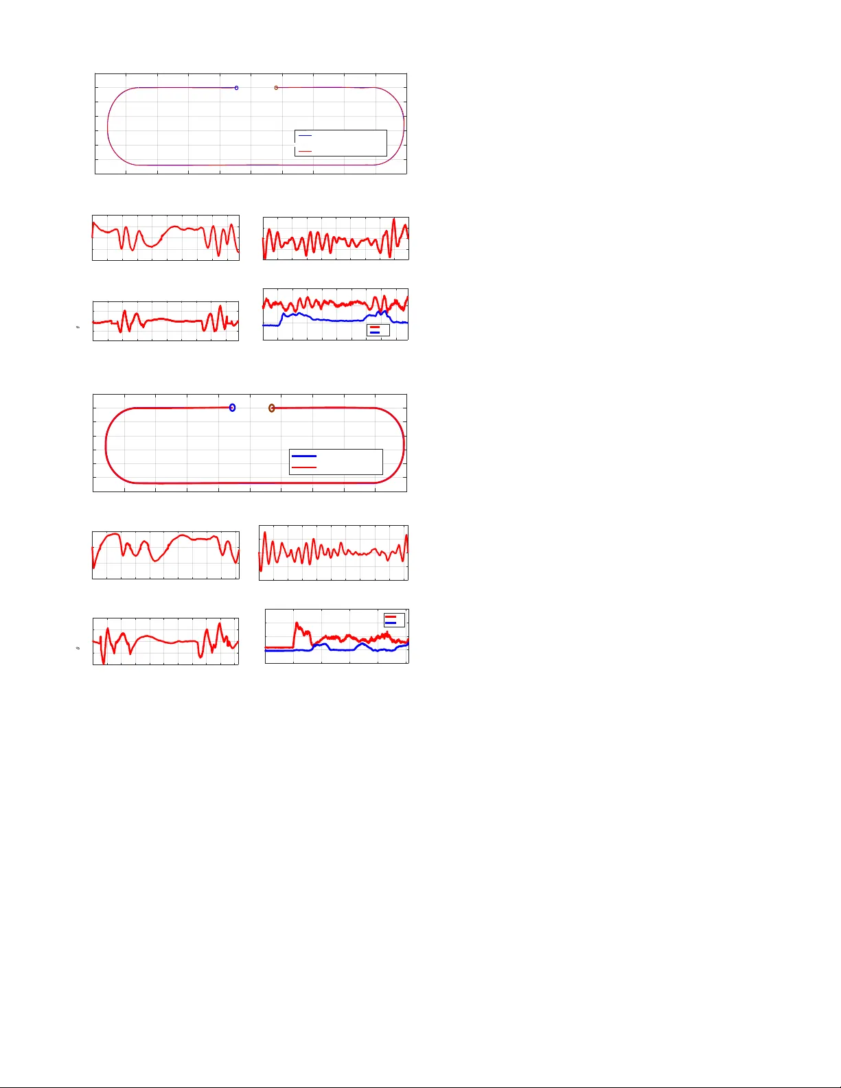
Modelling and Dynamic T racking Contr ol of Industrial V ehicles with T ractor -trailer Structur e Hongchao Zhao, Zhe Liu, Zhiqiang Li, Shunbo Zhou, W en Chen, Chuanzhe Suo, and Y un-Hui Liu Abstract — Existing works on contr ol of tractor-trailers sys- tems only consider the kinematics model without taking dynam- ics into account. Also, most of them tr eat the issue as a pur e con- trol theory problem whose solutions are difficult to implement. This paper presents a trajectory tracking control approach for a full-scale industrial tractor -trailers vehicle composed of a car- like tractor and arbitrary number of passive full trailers. T o deal with dynamic effects of trailing units, a for ce sensor is innovati vely installed at the connection between the tractor and the first trailer to measure the forces acting on the tractor . The tractor’ s dynamic model that explicitly accounts for the measured f orces is derived. A tracking controller that compen- sates the pulling/pushing for ces in real time and simultaneously drives the system onto desired trajectories is proposed. The propulsion map between throttle opening and the propulsion for ce is proposed to be modeled with a fifth-order polynomial. The parameters are estimated by fitting experimental data, in order to pro vide accurate driving f orce. Stability of the control algorithm is rigorously proved by L yapunov methods. Experiments of full-size vehicles ar e conducted to validate the performance of the control approach. I . I N T RO D U C T I O N Cargo transportation is one of the major tasks in big warehouses, railway stations, cargo terminals, airports, etc. A tractor pulling multiple passi ve trailers has been widely utilized for such tasks because of its higher efficienc y and lower cost, compared to a group of individual vehicles. An autonomous tractor -trailers v ehicle can further increase the producti vity and giv e a perfect solution to the serious shortage of human dri vers and their rapidly growing wages. Howe ver , these systems with payloads on trailers pose a com- plex nonlinear and underactuated dynamic control problem. Numerous works in the literature hav e been dev oted to this problem. Dif ferent control methods are proposed depending on the type of trailer hitching. A hitching is called “on-axle” when the rotary hitching joint is located at middle point of the trailer’ s wheel axles (points marked A in Fig. 1). While a hitching is called “off-axle” when the hitching joint is located somewhere between two consecutiv e trailers (points marked B in Fig. 1). Off-axle Kingpin hitching is broadly deployed in real applications thanks to its simpler mechanics, though the control problem is more difficult than that of on-axle This work is supported in part by the NSFC under Grant U1613218, in part by the Hong K ong ITC under Grant ITS/448/16FP , in part by the National Ke y Research and Development Program of China under Grant 2018YFB1309300, and in part by the VC Fund 4930745 of the CUHK T Stone Robotics Institute. All the authors are with the T Stone Robotics Institute and Department of Mechanical and Automation Engineering, The Chinese Univ ersity of Hong Kong, Shatin, HKSAR. Corresponding authors: Z. Liu and H. Zhao (zheliu@cuhk.edu.hk; hongchao.zhao@link.cuhk.edu.hk). joints. In our case, both on-axle and off-axle joints exist in the vehicle system (Fig. 1). Early contributions to tractor -trailers vehicle control mainly focused on on-axle hitching systems using nonlinear control theory . Laumond [1] prov ed the controllability of on- axle n-trailer vehicles with tools from differential geome- try . T ilbury et al. [2] proposed a Goursat canonical form, which is dual to the chained form, to model a class of driftless non-holonomic systems including the tractor with N trailers systems. Sordalen and Wichlund [3] then achiev ed the exponential stability using exact feedback linearization with a time-v arying state feedback control law , which pro- vided a theoretical basis for stabilizing the system at a goal pose or a path with constant curvature. Lamiraux and Laumond [4] applied the method for global obstacle-free path planning and trajectory following, but the results were quite complex. On the other side, howe ver , these feedback linearization techniques cannot be applied for systems with two or more of f-axle trailers, since the kinematics loses the property of differential flatness and becomes not feedback linearizable (Rouchon et al. [5], Bushnell [6]). This is why Lizarraga et al. [7] utilized some configurations that are able to be approximated locally by a chained form such that exponential stabilization can be achie ved. Bolzern et al. [8] approximated the kinematics of off-axle connection by an on-axle system model which has similar steady response and model dif ferences are re garded as disturbances. Alternati vely , control of off-axle tractor-trailers systems has also been approached by means of off-tracking analysis, i.e., analysis of trailer’ s tracking deviation from the tractor’ s path. This is mainly due to the property of open-loop stability . Dif ferent from the on-axle case, the trailers’ tracking errors do not necessarily grow with increasing number of units (Lee et al. [9]). In this sense, Bushnell et al. [10] inv estigated the off-tracking bounds in transition from a beeline to an arc of a circle and vice versa. This enables conv entional obstacle- av oidance path planners to be applied as if the tractor-trailers system is an enlarged tractor [11]. It is easy to observe that existing works on control of tractor-trailers systems only consider the kinematics model without taking dynamic effects into account. Besides, most of them treat the issue as a pure control theory problem whose solutions are difficult to implement. In our work, we treat the on-axle hitching in the system as an of f-axle hitching whose front connection bar has zero length. Partially using the ideas and methods from [11], trajectories that ensure safety handling of dynamic industrial scenarios can then be planned. Though the planned trajectory L � A B B B A A Lead tr act or T r ai ler s Fig. 1. T ractor-trailers vehicle and its geometric model. is for the lead tractor, it can simultaneously guarantee the whole system to be collision-free and ex ecutable for time- critical maneuvers. Therefore, the control issue of the tractor - trailers system can be simplified to the control problem of the single lead tractor . Since this paper focuses on trajectory control, details for trajectory planning will not be presented and we assume the reference trajectory is giv en in our problem. T o the best of our knowledge, this paper is the first to report trajectory control of full-size industrial tractor-trailers vehicles. The novelty of this work manifests in two aspects. Firstly , a two-dimensional force sensor is installed at the connection (rightmost B point in Fig. 1) between the tractor and the first trailer . The tractor’ s dynamic model that explicitly accounts for the measured forces is introduced. A trajectory tracking controller is proposed to compensate the forces in real time and simultaneously drive the tractor onto the desired trajectory . In contrast to e xisting works, by reflecting trailers’ motion ef fects onto the real-time force measurements, our approach considers the complex dynamic effects introduced by trailers, such as varying number and div erse configurations of and different payloads on the trail- ers. Moreov er , since the lead tractor is the final object to be controlled, the controller does not require knowledge of trailers’ dynamic parameters (mass, moment of inertia, etc.) or the una v ailable states of the trailers. Secondly , though the control of wheeled mobile robots has always been a hot topic for numerous research activities (see [12], [13], [14], [15], [16]), real-world implementation of trajectory tracking for full-scale vehicles is barely seen, let alone for the tractor-trailers systems. The main challenge is to achie ve high precision of acceleration and deacceleration commands. Hence, our second novelty arises from applying a fifth-order polynomial to model the map between propulsion force and throttle opening and velocity . The parameters are estimated by fitting the experimental data in order to provide accurate driving force for propulsion of the system and compensation of trailer dynamics, when directly controlling the throttle. The paper is organized as follows. Section II presents the dynamic model of the lead tractor . Section III details the controller design and stability analysis. Section IV shows the practical implementation on the full-size industrial tractor- trailers vehicle. Section V concludes the work. I I . D Y NA M I C M O D E L I N G The tractor is a rear -dri ve, front-steer car-like v ehicle. T o deriv e its dynamics, the nonlinear one-track model [17] is y v x v x H y H d F ( , ) xy r F ( , ) gg xy f F Fig. 2. Nonholonomic tractor model with force measurements. employed where the front and rear wheels are respecti vely replaced by an intermediate wheel in the middle, see Fig. 2. It is assumed that the motion is planar and the height of Center of Gravity (COG) is zero, thus the road bank and grade are not considered and the roll and pitch dynamics are neglected. The rolling resistance and aerodynamics drag are also assumed to be negligible. In this sense, the tractor is subject to the driving force F d that is modeled to act at center of the rear wheel, two lateral slip forces F r , F f applied perpendicular to the wheels and two measurable forces H x and H y that are exerted on the tractor at the off-axle hitch point by trailing trailers. Be noted that the hitch joint does not transmit torque. Applying the Newton-Euler method, we obtain the follo wing dynamic equations. m ˙ v x = F d − F f sin ψ − H x + mv y ˙ θ (1) m ˙ v y = F r + F f cos ψ + H y − mv x ˙ θ (2) J ¨ θ = aF f cos ψ − bF r − ( b + c ) H y , (3) where m is the tractor mass, J is the moment of inertia, v x , v y are longitudinal and lateral velocity (in tractor’ s local frame) at COG. ψ is the steering angle, θ is tractor’ s yaw angle, a , b are distances from COG to front wheel and rear wheel respecti vely and c is the distance between the force sensor and the rear wheel. The position of COG is denoted as ( x g , y g ) in the inertial frame. For our application, considering the required low speed of the tractor ( ≤ 8 km/h when towing trailers in industrial scenarios), slippage-free condition can always be assumed to hold at the wheels [17]. Hence, two nonholonomic constraints (4), (5) respectiv ely for rear and front wheels can further be introduced. ˙ y g cos θ − ˙ x g sin θ = b ˙ θ (4) ˙ y g cos( θ + ψ ) − ˙ x g sin( θ + ψ ) = − a ˙ θ cos ψ (5) The rotational transformation between velocity in local and inertial frame is as below . ˙ x g ˙ y g = cos θ − sin θ sin θ cos θ v x v y (6) Substituting (6) into (4), (5) yields (7) and it’ s differentiation (8). v y = b ˙ θ , ˙ θ = v x tan ψ L (7) ˙ v y = b ¨ θ , ¨ θ = ˙ v x tan ψ L + ˙ ψ v x L cos 2 ψ (8) Combining (1) - (8) and choosing x g y g θ v x as part of the states, we can get the simplified vehicle dynamic equations (9) - (12): ˙ x g = v x cos θ − b sin θ tan ψ L (9) ˙ y g = v x sin θ + b cos θ tan ψ L (10) ˙ θ = v x tan ψ L (11) ˙ v x = ϕ 1 + ϕ 2 ( F d − H x ) − ϕ 3 H y (12) with ϕ 1 = − (1 / Z )( mb 2 + J ) tan ψ ˙ ψ v x ϕ 2 = (1 / Z ) L 2 cos 2 ψ ϕ 3 = (1 / Z ) L 2 c sin ψ cos ψ Z = cos 2 ψ [ L 2 m + ( mb 2 + J ) tan 2 ψ ] (13) Furthermore, to ensure and improve the capability of trajec- tory tracking control, it is essential to model the actuation process. The dynamic behavior of the steering actuator is assumed, and experimentally prov en, to be well-captured by a first-order lag element ˙ ψ = ( u 2 − ψ ) 1 τ , (14) where τ denotes the time constant and u 2 is the control input for steering. The driving force F d is either the propulsion force F p transmitted to the rear wheel from the engine through driv eline or braking force F b generated by brake actuation. The engine torque is normally modeled as being proportional to the throttle opening u 1 and also being a second-order polynomial w .r .t the engine speed [18], [19]. The engine speed can also be proportionally related to vehicle speed v x , when assuming that the torque con verter in the tractor is locked and that there is no slippage at the wheels [20]. The propulsion force can be further assumed to hav e a proportional relationship with engine torque [18]. In light of these ideas and also considering the inherently complex nonlinear mapping of the tractor’ s driv eline, we propose the fifth-order-polynomial propulsion map (15) be- tween the propulsion force and the throttle opening and vehicle velocity . The coefficients Φ are estimated by fitting experimental data. As shown in Fig. 3, each of the black curves corresponds to a set of experimental force-speed data under a certain lev el of throttle opening. The throttle opening value is set from 0 to 300 and a few samples between are chosen to generate different black curves. The velocity is less than 5 m/s , which is the normal operation range for industrial tractors. The propulsion force is achiev ed in real time with an EKF force estimator combining IMU readings, encoders on the steering wheel and driven wheels and the vehicle dynamic model. The fifth-order polynomial is found to be the best candidate to fit the data as a propulsion map in the sense of simplicity and accuracy , compared to polynomials of other orders. The colored surface in Fig. 3 is the resultant polynomial map after data fitting. Fig. 3. Map between propulsion force and throttle opening and velocity . F p = u 1 1 v x v 2 x v 3 x v 4 x v 5 x β 1 β 2 β 3 β 4 β 5 β 6 = u 1 V T Φ (15) The braking force F b generated by brake actuation is mod- eled to be proportional to the av ailable control input of braking pressure u 3 . F b = u 3 n b (16) with n b the constant ratio. Finally , equations (9) - (16) constitute the complete dynamic model of the tractor . I I I . N O N L I N E A R T R A J E C T O RY C O N T RO L A. T rajectory Repr esentation Since the dynamic equations for heading (11), v elocity (12), steering (14) and driving force (15)(16) do not depend on the position of the tractor , the coordinates of interest ( x g , y g ) can be redefined as being the center point ( x, y ) of the tractor’ s rear axle. Therefore, equations (9) and (10) can be re written as ˙ x = v x cos θ (17) ˙ y = v x sin θ (18) The trajectory planning is then to continuously parameterize the desired position and orientation of the point ( x, y ) . As mentioned, the reference trajectory is planned for the tractor, and it also respects collision-free conditions for the whole tractor-trailers system. Besides, the planned trajectory is required to guarantee sufficient smoothness and account for actuation limitations introduced by the structure of the whole system. The reference trajectory is assumed to be giv en and is formulated as follows q d ( t ) = [ x d ( t ) , y d ( t ) , θ d ( t ) , v d ( t )] T ˙ q d ( t ) = [ ˙ x d ( t ) , ˙ y d ( t ) , ˙ θ d ( t ) , ˙ v d ( t )] T (19) with v d = q ˙ x 2 d ( t ) + ˙ y 2 d ( t ) , θ d = atan2( ˙ y d ( t ) , ˙ x d ( t )) It should be noted that, to av oid the jack-knife phenomenon in tractor-trailers system, the desired velocity v d is always positiv e. m i m j ( , ) xy d i d j d ( , ) dd xy i j e e x e y Fig. 4. T ransformation of error coordinates. B. Switching P olicy between Thr ottle and Brak e Contr ol In our work, the control input for driving force is exclu- siv ely throttle opening rate u 1 or braking pressure u 3 , which means only one type of input applies in a control cycle to generate F d . The switch between throttle and brake depends on the sign of the desired value ω 2 of the driving force, which is provided by the nonlinear control la w presented in the follo wing subsection. The switch policy is gi ven by F d = u 1 V T Φ ω 2 > 0 u 3 n b ω 2 < 0 (20) C. T rajectory T rac king Contr ol Design W e first define the posture and velocity errors with respect to a Frenet frame as follows (see Fig. 4). x e = ( x − x d ) cos θ d + ( y − y d ) sin θ d y e = ( y − y d ) cos θ d − ( x − x d ) sin θ d θ e = θ − θ d v e = v x − v d (21) T aking the deri v ativ e and applying equations (11)-(18), the system finally becomes ˙ x e = v x cos θ e + ˙ θ d y e − v d (22) ˙ y e = v x sin θ e − ˙ θ d x e (23) ˙ θ e = v x c ψ − ˙ θ d (24) ˙ v e = ϕ 1 + ϕ 2 ( F d − H x ) − ϕ 3 H y − ˙ v d (25) ˙ c ψ = ( tan ψ L ) 0 = ( 1 L + Lc 2 ψ ) ˙ ψ (26) ˙ ψ = ( u 2 − ψ ) 1 τ (27) F d = F p = u 1 V T Φ , or F b = u 3 n b (28) Therefore, when all the states are av ailable, the tracking control objecti ve is to find control laws for throttle opening rate u 1 , steering input u 2 and braking pressure u 3 , such that lim t →∞ [ x e ( t ) , y e ( t ) , θ e ( t ) , v e ( t )] = 0 . Consider , first, only the truncated system (22) - (25), and pretend that c ψ in (24) and F d in (25) can be directly manipulated by ω 1 and ω 2 respectiv ely . W e propose the following lemma. Lemma 1: The virtual control input ω 1 and ω 2 giv en by ω 1 = 1 θ e [ x e (1 − cos θ e ) − y e sin θ e ] − k θ θ e + ˙ θ d v d (29) ω 2 = H x + 1 ϕ 2 ( ϕ 3 H y − ϕ 1 + ˙ v d − k v v e − x e + k θ θ 2 e − ˙ θ d v d θ e ) (30) with k θ , k v > 0 , makes [ x e ( t ) , y e ( t ) , θ e ( t ) , v e ( t )] = 0 of the partial system (22) - (25) globally asymptotically stable. Pr oof: The scalar function V 1 is proposed to be a L yapunov function candidate, V 1 = 1 2 ( x 2 e + y 2 e + θ 2 e + v 2 e ) (31) its time deri vati ve is given by ˙ V 1 = x e ˙ x e + y e ˙ y e + θ e ˙ θ e + v e ˙ v e = x e ( v x cos θ e + ˙ θ d y e − v d ) + y e ( v x sin θ e − ˙ θ d x e ) + θ e ( v x ω 1 − ˙ θ d ) + v e [ ϕ 1 + ϕ 2 ( ω 2 − H x ) − ϕ 3 H y − ˙ v d ] = − k θ v d θ 2 e − k v v 2 e ≤ 0 Considering the boundness of variables inside the system, from Barbalat’ s lemma [21], we can easily show that lim t →∞ ˙ V 1 = 0 . Then, lim t →∞ θ e = 0 , lim t →∞ v e = 0 with F d = ω 2 and v e ≡ 0 = ⇒ ˙ v e ≡ 0 , from (30) and (25), we get x e = 0 (32) with c ψ = ω 1 and θ e ≡ 0 = ⇒ ˙ θ e ≡ 0 , from (29) and (24), we get y e = 0 (33) Notice that in (29), terms sin θ e /θ e and (1 − cos θ e ) /θ e hav e remov able singularities and are accurately implemented with T aylor series approximation. Therefore, we can conclude the asymptotic stability of [ x e ( t ) , y e ( t ) , θ e ( t ) , v e ( t )] = 0 1) Contr ol Design for Thr ottle and Steering: First con- sider the situation when the desired driving force ω 2 > 0 , where F d = F p = u 1 V T Φ . Follo wing the backstepping procedure [21], we further design the real control input u 1 , u 2 such that c ψ and F p con verge to the virtual control law ω 1 and ω 2 respectiv ely . W ith the kno wn polynomial coefficients Φ and measurable velocity vector V , driving force F d can be directly manipu- lated by u 1 . Define the distance between c ψ and its goal ω 1 as δ ψ = c ψ − ω 1 (34) we propose the following theorem, Theor em 1: When ω 2 > 0 , the control law for the throttle input u 1 and steering input u 2 giv en by u 1 = ω 2 ( V T Φ ) − 1 (35) u 2 = τ 1 L + Lc 2 ψ ( ˙ ω 1 − v x θ e − k ψ δ ψ ) + ψ (36) with k ψ > 0 , forces [ x e , y e , θ e , v e , δ ψ ] to asymptotically con verge to zero. Pr oof: From (26) and (27), the time deriv ativ e of (34) yields ˙ δ ψ = ˙ c ψ − ˙ ω 1 = ( 1 L + Lc 2 ψ )( u 2 − ψ ) 1 τ − ˙ ω 1 (37) Define the ne w composite L yapunov function candidate V 2 = V 1 + 1 2 δ 2 ψ its time deri vati ve yields ˙ V 2 = ˙ V 1 + δ ψ ˙ δ ψ (38) = x e ( v x cos θ e + ˙ θ d y e − v d ) + y e ( v x sin θ e − ˙ θ d x e ) + θ e [ v x ( ω 1 + δ ψ ) − ˙ θ d ] + v e [ ϕ 1 + ϕ 2 ( u 1 V T Φ − H x ) − ϕ 3 H y − ˙ v d ] + δ ψ ( ˙ c ψ − ˙ ω 1 ) = − k θ v d θ 2 e − k v v 2 e + θ e v x δ ψ + δ ψ [( 1 L + Lc 2 ψ )( u 2 − ψ ) 1 τ − ˙ ω 1 ] = − k θ v d θ 2 e − k v v 2 e − k ψ δ 2 ψ ≤ 0 Analogous to Lemma 1, we can easily conclude that lim t →∞ ˙ V 2 = 0 , which means lim t →∞ θ e = 0 , lim t →∞ v e = 0 , lim t →∞ δ ψ = 0 (39) W ith δ ψ = 0 , and from (34), we hav e c ψ = ω 1 . With (35), F p is directly controlled to be ω 2 . Therefore, (32) and (33) still hold. Hence, the statement in the theorem can be readily prov ed. Be noted again that the deriv ati ves of the expressions sin θ e /θ e and (1 − cos θ e ) /θ e in ˙ ω 1 also hav e remov able singularities, which poses no problem for accurate imple- mentation. 2) Contr ol Design for Brake and Steering: When the desired driving force ω 2 < 0 , then F d = F b = u 3 n b . W e need to design steering input u 2 and braking input u 3 , such that c ψ and F b con verge to the virtual control input ω 1 and ω 2 respectiv ely . W ith kno wledge of the value n b , F b can be directly manipulated by control input u 3 . u 2 needs to be further designed. W e propose the following theorem, Theor em 2: When ω 2 < 0 , the control law for steering input u 2 and brake input u 3 giv en by u 2 = τ 1 L + Lc 2 ψ ( ˙ ω 1 − v x θ e − k ψ δ ψ ) + ψ (40) u 3 = ω 2 /n b (41) asymptotically stabilizes [ x e , y e , θ e , v e ] = 0 of the system (22)-(28). Pr oof: Using again the lyapunov function candidate V 2 = V 1 + 1 2 δ 2 ψ with (29), (30), (37) and analogous to Lemma 1, we get ˙ V 2 = − k θ v d θ 2 e − k v v 2 e − k ψ δ 2 ψ ≤ 0 (42) Mimicking the same ar guments applied in the proof of Lemma 1 and Theorem 1, we can readily sho w that [ x e , y e , θ e , v e ] = 0 is asymptotically stable. 3) Discussion: Since (21) is a diffeomorphic coor- dinate transformation, the con ver gence of error vector [ x e , y e , θ e , v e ] to zero guarantees the con ver gence of trajec- tory tracking. I V . P R A CT I C A L I M P L E M E N TA T I O N A N D R E S U L T S In this section, we implement the derived trajectory track- ing controller with a full-size industrial tractor -trailers v ehi- cle on an e ven test site inside a big warehouse (Fig. 5). The tractor is the T oyota 52-2TD25 model and is retrofitted with driv e-by-wire throttling, braking and steering. The tractor as well as the full trailers (dollies) in the experiments are all standard models applied in the Hong K ong International Airport for luggage or cargo transportation. All the physical parameters of the tractor (mass, inertia, COG and dimen- sions) can be determined with standard measurements. W e adopt the 3-axis force sensor ME K3D160 with a measuring range of ± 50 KN (enough for normal indus- trial task ex ecution) in each mutually perpendicular axes. Only two forces parallel to the road surface are counted. The force sensor is fix ed on the tractor and is con- nected to the trailer bar via an intermediate link. Due to the small dimension of the link, we can assume that the trailer is directly connected to the force sensor with a hitch joint. Y aw rate and acceleration measurements are obtained with Xsens MT i-300-AHRS IMU. The self- localization process (providing position and orientation) is conducted by fusing sensory information from UWB, 3D laser scanner , cameras and inertial and odometry measure- ments. The coef ficient vector is calculated of f-line as Φ = 26 . 2 − 9 . 999 3 . 018 − 1 . 041 0 . 2354 − 0 . 021 T . W e remov e the obstacles and make the tractor running in a roundabout way to eliminate possible neg ati ve effects of the trajectory planning lev el on the tracking results. W e con- ducted two experiments with different number and different size of trailers. Fig. 6 sho ws the results of the experiment where the tractor to ws two relati vely small full trailers. The weight of one small full trailer is 630kg. Besides, sandbags with total weight of 2000kg are loaded on the first trailer to act as extra payload. The desired trajectory is planned online and keeps the tractor running with a velocity of 1 m/s along the trajectory . The total running time is 98 s. The position error is calculated by | e p ( t ) | = p x 2 e ( t ) + y 2 e ( t ) , with its sign being negati ve when the tractor is on the left of the desired trajectory . Fig. 7 shows the results of the second experiment where the tractor tows two extra big full trailers, with each weighing 1300kg. The running time is 103 s and the con- stant desired velocity is 0.8 m/s. Above results demonstrate F or ce sen so r Fig. 5. The autonomous full-size industrial tractor-trailers vehicle. -30 -25 -20 -15 -10 -5 0 5 10 15 20 X / m -12 -10 -8 -6 -4 -2 0 2 Y / m Reference Trajectory Tractor Trajectory start position stop position 0 10 20 30 40 50 60 70 80 90 t / s -0.1 -0.05 0 0.05 0.1 Position Error e p / m 0 10 20 30 40 50 60 70 80 90 t / s -0.1 -0.05 0 0.05 0.1 v e / m/s 0 10 20 30 40 50 60 70 80 90 t / s -0.04 -0.02 0 0.02 0.04 e / rad 0 10 20 30 40 50 60 70 80 90 t / s -1000 0 1000 2000 Force measure / N Hx Hy Fig. 6. T rajectory control performance with two full trailers and payload. -30 -25 -20 -15 -10 -5 0 5 10 15 20 X / m -12 -10 -8 -6 -4 -2 0 2 Y / m Reference Trajectory Tractor Trajectory start position stop position 0 10 20 30 40 50 60 70 80 90 100 t / s -0.1 -0.05 0 0.05 Position Error e p / m 0 10 20 30 40 50 60 70 80 90 100 t / s -0.1 -0.05 0 0.05 0.1 v e / m/s 0 10 20 30 40 50 60 70 80 90 100 t /s -0.04 -0.02 0 0.02 0.04 e / rad 0 20 40 60 80 100 t / s -2000 0 2000 4000 6000 Force measure / N Hx Hy Fig. 7. T rajectory control performance with four full trailers and payload. precise and robust performance of the proposed trajectory controller under different physical properties and dynamic configurations of the industrial tractor-trailers vehicle. V . C O N C L U S I O N In order to handle the complex dynamics of industrial vehicles with tractor-trailer structure and finally realize the autonomous trajectory tracking control, a force sensor is proposed to be installed at the connection between the tractor and the first trailer . The tractor’ s dynamic model that explicitly accounts for the measured forces has been deriv ed. Both throttle & steering control and brake & steering control are proposed. The practical implementation results on full-size industrial tractor -trailers vehicles have shown good performance of the proposed approaches in trajectory tracking and the handling of complex dynamics. R E F E R E N C E S [1] J.-P . Laumond, “Controllability of a multibody mobile robot, ” IEEE T ransactions on Robotics and Automation , vol. 9, no. 6, pp. 755–763, 1993. [2] D. Tilb ury , J.-P . Laumond, R. Murray , S. Sastry , and G. W alsh, “Steer- ing car-like systems with trailers using sinusoids, ” in Proceedings of IEEE International Confer ence on Robotics and Automation , 1992, pp. 1993–1998. [3] O. Sordalen and K. Wichlund, “Exponential stabilization of a car with n trailers, ” in Pr oceedings of 32nd IEEE Conference on Decision and Contr ol , 1993, pp. 978–983. [4] F . Lamiraux and J.-P . Laumond, “Flatness and small-time controllabil- ity of multibody mobile robots: Application to motion planning, ” IEEE T ransactions on Automatic Contr ol , v ol. 45, no. 10, pp. 1878–1881, 2000. [5] P . Rouchon, M. Fliess, J. L ´ evine, and P . Martin, “Flatness, motion planning and trailer systems, ” in Proceedings of 32th IEEE Confer ence on Decision and Control , vol. 3, 1993, pp. 2700–2700. [6] L. Bushnell, “ An obstacle av oidance algorithm for a car pulling trailers with off-axle hitching, ” in Proceedings of 34th IEEE Conference on Decision and Contr ol , vol. 4, 1995, pp. 3837–3842. [7] D. A. Liz ´ arraga, P . Morin, and C. Samson, “Chained form approxima- tion of a driftless system: Application to the exponential stabilization of the general n-trailer system, ” International Journal of Contr ol , vol. 74, no. 16, pp. 1612–1629, 2001. [8] P . Bolzern, R. M. DeSantis, and A. Locatelli, “Path-tracking for articulated vehicles with off-axle hitching, ” IEEE T ransactions on Contr ol Systems T echnology , vol. 6, no. 4, pp. 515–523, 1998. [9] J.-H. Lee, W . Chung, M. Kim, and J.-B. Song, “ A passive multiple trailer system with of f-axle hitching, ” International Journal of Contr ol, Automation, and Systems , vol. 2, no. 3, pp. 289–297, 2004. [10] L. Bushnell, B. Mirtich, A. Sahai, and M. Secor, “Off-tracking bounds for a car pulling trailers with kingpin hitching, ” in Proceedings of 33rd IEEE Conference on Decision and Contr ol , vol. 3, 1994, pp. 2944– 2949. [11] L. Bushnell, “ An obstacle av oidance algorithm for a car pulling trailers with off-axle hitching, ” in Proceedings of 34th IEEE Conference on Decision and Contr ol , vol. 4, 1995, pp. 3837–3842. [12] P . Morin and C. Samson, “Motion control of wheeled mobile robots, ” Springer Handbook of Robotics , pp. 799–826, 2008. [13] G. Campion and W . Chung, “Wheeled robots, ” Springer handbook of r obotics , pp. 391–410, 2008. [14] S. Zhou, Z. Miao, Z. Liu, H. Zhao, H. W ang, H. Chen, and Y .-H. Liu, “V ision-based state estimation and trajectory tracking control of car- like mobile robots with wheel skidding and slipping, ” in Pr oceedings of IEEE/RSJ International Confer ence on Intelligent Robots and Systems , 2018, pp. 4270–4275. [15] Z. Liu, H. W ang, L. Xu, Y .-H. Liu, J. Lu, and W . Chen, “ A failure- tolerant approach to synchronous formation control of mobile robots under communication delays, ” in Proceedings of IEEE International Confer ence on Robotics and Automation , 2018, pp. 1661–1666. [16] S. Zhou, Z. Liu, H. W ang, H. Zhao, and Y .-H. Liu, “V ision-based dynamic control of car-like mobile robots, ” in Pr oceedings of IEEE International Conference on Robotics and Automation , 2019, pp. 6631–6636. [17] R. Rajamani, V ehicle dynamics and control . Springer Science & Business Media, 2011. [18] K. J. Astr ¨ om and R. M. Murray , F eedback systems: An introduction for scientists and engineers . Princeton university press, 2010. [19] V . Milan ´ es, J. V illagr ´ a, J. P ´ erez, and C. Gonz ´ alez, “Low-speed longitudinal controllers for mass-produced cars: A comparative study , ” IEEE Tr ansactions on Industrial Electronics , vol. 59, no. 1, pp. 620– 628, 2011. [20] R. Rajamani, H.-S. T an, B. K. Law , and W .-B. Zhang, “Demonstration of integrated longitudinal and lateral control for the operation of au- tomated vehicles in platoons, ” IEEE T ransactions on Contr ol Systems T echnology , vol. 8, no. 4, pp. 695–708, 2000. [21] J.-J. E. Slotine, W . Li et al. , Applied nonlinear contr ol . Prentice hall Englew ood Cliffs, NJ, 1991, vol. 199, no. 1.
Original Paper
Loading high-quality paper...
Comments & Academic Discussion
Loading comments...
Leave a Comment