Controller Synthesis for Multi-Agent Systems With Intermittent Communication: A Metric Temporal Logic Approach
This paper develops a controller synthesis approach for a multi-agent system (MAS) with intermittent communication. We adopt a leader-follower scheme, where a mobile leader with absolute position sensors switches among a set of followers without abso…
Authors: Zhe Xu, Federico M. Zegers, Bo Wu
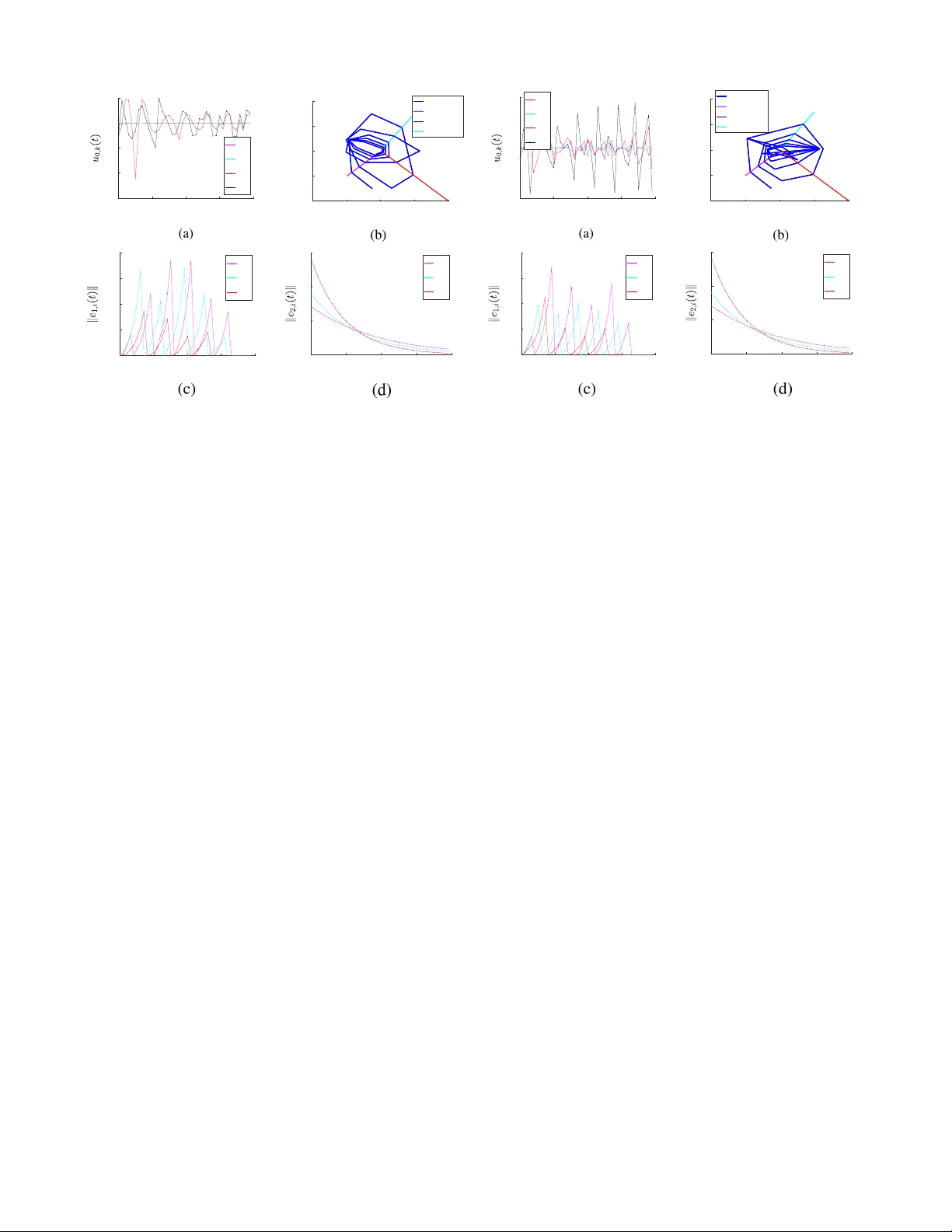
Controller Synthesis for Multi-Agent Systems W ith Intermittent Communication: A Metric T emporal Logic Approach Zhe Xu, Federico M. Zegers, Bo W u, W arren Dixon and Ufuk T opcu Abstract — This paper develops a controller synthesis ap- proach for a multi-agent system (MAS) with intermittent communication. W e adopt a leader-follow er scheme, where a mobile leader with absolute position sensors switches among a set of follo wers without absolute position sensors to pr ovide each follo wer with intermittent state inf ormation. W e model the MAS as a switched system. The follo wers are to asymptotically r each a predetermined consensus state. T o guarantee the stability of the switched system and the consensus of the follo wers, we derive maximum and minimal dwell-time conditions to constrain the intervals between consecutive time instants at which the leader should provide state information to the same follower . Furthermore, the leader needs to satisfy practical constraints such as charging its battery and staying in specific regions of interest. Both the maximum and minimum dwell-time condi- tions and these practical constraints can be expressed by metric temporal logic (MTL) specifications. W e iteratively compute the optimal control inputs such that the leader satisfies the MTL specifications, while guaranteeing stability and consensus of the follo wers. W e implement the pr oposed method on a case study with three mobile robots as the follo wers and one quadrotor as the leader . I . I N T R O D U C T I O N Coordination strategies for multi-agent systems (MAS) hav e been traditionally designed under the assumption that state feedback is continuously a vailable. Howe ver , contin- uous communication over a network is often impractical, especially in mobile robot applications where shadowing and fading in the wireless communication can cause unreliability , and each agent has limited energy resources [1], [2]. Due to these constraints, there is a strong interest in dev el- oping MAS coordination methods that rely on intermittent information over a communication network. The results in [3]–[8] develop event-trigg er ed and self-trigger ed controllers that utilize sampled data from networked agents only when triggered by conditions that ensure desired stability and performance properties. Howe ver , these results require a network represented by a strongly connected graph to enable agent coordination. This requirement of a strongly connected network induces constraints on the motion of the individual agents and additional maneuvers that may deviate from their primary purpose. Event-triggered and self-triggered control Zhe Xu and Bo W u are with the Oden Institute for Computational Engineering and Sciences, University of T exas, Austin, Austin, TX 78712, Federico M. Zegers and W arren Dixon are with the Department of Mechan- ical and Aerospace Engineering, Uni versity of Florida, Gainesville, Florida 32611, Ufuk T opcu is with the Department of Aerospace Engineering and Engineering Mechanics, and the Oden Institute for Computational Engineer- ing and Sciences, University of T exas, Austin, Austin, TX 78712, e-mail: zhexu@utexas.edu, fredzeg@ufl.edu, bwu3@ute xas.edu, wdixon@ufl.edu, utopcu@utexas.edu. methods can also be used to coordinate the agents that com- municate with a central base station or cloud intermittently as in [9], where submarines intermittently surface to obtain state information about themselves and their neighbors from a cloud. Howe ver , such a coordination strategy also requires additional maneuvers from the submarines that detract from their primary purpose. Depending on the application and/or en vironment, some of the agents in a MAS may not be equipped with absolute position sensors. In such scenarios, the results in [3]–[8] are in valid. Therefore, there is a need for distributed methods capable of coordinating these agents that are not equipped with absolute position sensors while utilizing intermittent in- formation. Moreov er , such methods should not require agents to perform additional maneuvers to ensure the connectivity of the network. In [10], a set of followers operating with inaccurate position sensors are able to reach consensus at a desired state while a leader intermittently provides each follower with state information. By introducing a leader, the followers are able to perform their tasks without the need to perform additional maneuvers to obtain state information. Building on the work of [10], we adopt a leader-follower scheme, where the MAS is modeled as a switched system [11], [12]. As an illustrativ e example shown in Fig. 1, the three followers need to reach consensus at the center of the green feedback region and one leader agent is to provide intermittent state information to each follower . T o guarantee the stability of the switched system and consensus of the followers, we deriv e maximum and minimal dwell-time con- ditions to constrain the intervals between consecutiv e time instants at which the leader should provide state information to the same follower . The maximum and minimum dwell-time conditions can be encoded by metric temporal logic (MTL) specifications [13]. Such specifications have also been used in many robotic ap- plications for time-related specifications [14]. Furthermore, as the leader is typically more energy-consuming and safety- critical due to the high-quality sensing, communication and mobility equipments, the leader is likely required to satisfy additional MTL specifications for practical constraints such as charging its battery and staying in specific regions. In the example shown in Fig. 1, the leader needs to satisfy an MTL specification “ r each the char ging station G 1 or G 2 in every 6 time units and always stay in the yellow re gion D ”. W e design the followers’ controllers such that guarantees on the stability of the switched system and consensus of the followers hold, provided that the maximum and minimal dwell-time conditions are satisfied. Then we synthesize the leader agent follower agent 1 follower agent 2 follower agent 3 feedback region charging station G 1 G 2 yellow region D charging station workspace Fig. 1: Illustrative example of a MAS with a leader (quadro- tor) and three followers (mobile robots). leader’ s controller to satisfy the same MTL specifications that encode the maximum and minimal dwell-time conditions and the additional practical constraints. There is a rich literature on controller synthesis subject to temporal logic specifica- tions [15]–[25]. For linear or switched linear systems, the controller synthesis problem can be con verted into a mixed- integer linear programming (MILP) problem [17], [18]. Ad- ditionally , as the followers are not equipped with absolute position sensors, we design an observer to estimate the followers’ states and the state estimates can change abruptly due to the intermittent communication of state information. Therefore, we solve the MILP problem iterativ ely to account for such abrupt changes. W e provide an implementation of the proposed method on a simulation case study with three mobile robots as the followers and one quadrotor as the leader . The results in two dif ferent scenarios show that the synthesized controller can lead to satisfaction of the MTL specifications, while achieving the stability of the switched system and consensus of the followers. I I . B AC K G R O U ND A N D P R OB L E M F O R M U L A T I O N A. Agent Dynamics Consider a multi-agent system (MAS) consisting of Q followers ( Q ∈ Z > 0 1 ) index by i ∈ F , { 1 , ..., Q } and a leader indexed by 0 . Let the time set be T = R ≥ 0 . Let y 0 , y i : T → R z denote the position of the leader and follower i , respectiv ely . Let x 0 : T → R l and x i : T → R m denote the state of the leader and follo wer i , respecti vely . The linear time-inv ariant dynamics of the leader and follo wer i are ˙ x 0 ( t ) = A 0 x 0 ( t ) + B 0 u 0 ( t ) , y 0 ( t ) = C 0 x 0 ( t ) , ˙ x i ( t ) = Ax i ( t ) + B u i ( t ) + d i ( t ) , y i ( t ) = C x i ( t ) , (1) where A 0 ∈ R l × l , A ∈ R m × m , B 0 ∈ R l × n , B ∈ R m × n , C 0 ∈ R z × l , C ∈ R z × m . Here, u 0 , u i : T → R n denote the control inputs of the leader and follower i , respecti vely , and 1 Z > 0 denotes the set of positi ve integers. d i : T → R m is an exogenous disturbance. For simplicity , we assume that λ max ( A ) 2 ∈ R > 0 and B has full row rank. B. Sensing and Communication Each follower is equipped with a relativ e position sensor and hardware to enable communication with the leader . Since the followers lack absolute position sensors, they are not able to localize themselves within the global coordinate system. Nev ertheless, the follo wers can use their relativ e position sensors to enable self-localization relative to their initially known locations. Howe ver , relative position sensors like encoders and inertial measurement units (IMUs) can produce unreliable position information since e.g., wheels of mobile robots may slip and IMUs may generate noisy data. Hence, the d i ( t ) term in (1) models the inaccurate position measurements from the relative position sensor of follower i as well as any external influences from the environment. Navigation through the use of a relativ e position sensor results in dead-reckoning, which becomes increasingly more inaccurate with time if not corrected. On the other hand, the leader is equipped with an absolute position sensor and hardware to enable communication with each follower . Unlike a relativ e position sensor , an absolute position sensor allows localization of the agents within the global coordinate system. The followers’ task is to reach consensus to a prede- termined state x g ∈ R m . A feedback region (see Fig. 1) centered at the position C x g ∈ R z with radius R g ∈ R > 0 is capable of providing state information to each follo wer i ∈ F once k y i ( t ) − C x g k = k C x i ( t ) − C x g k ≤ R g . The leader’ s task is to provide state information to each follower while they navigate to x g with the intermittent state information. Both the leader and the followers are equipped with digital communication hardware where communication is only possible at discrete time instants. Let R c ∈ R > 0 and R s ∈ R > 0 denote the communication and sensing radii of each agent, respectiv ely . For simplicity , let R c = R s , R . The leader provides state information to the follower i (i.e., services the follower i ) if and only if k y i ( t ) − y 0 ( t ) k ≤ R and the communication channel of the follower i is on. W e define the communication switching signal ζ i for follower i as ζ i = 1 if the communication channel is on for follower i ; and ζ i = 0 if the communication channel is off for follower i . W e use t i s ≥ 0 to indicate the s th servicing time instance for follower i . Hence, the ( s + 1) th servicing time instant for follower i is 3 t i s +1 , inf t ≥ t i s : ( k y i ( t ) − y 0 ( t ) k ≤ R ) ∧ ( ζ i ( t ) = 1) where ∧ denotes the conjunction logical connective. C. State Observer and Error Dynamics The followers, not equipped with absolute position sen- sors, implement the following model-based observer to esti- 2 λ max ( A ) denotes the maximum singular value of A . 3 For s = 0 , t i 0 is the initial time, for simplicity we take t i 0 = 0 . mate the state of each follower i ∈ F : ˙ ˆ x i ( t ) , A ˆ x i ( t ) + B u i ( t ) , t ∈ t i s , t i s +1 , ˆ x i t i s , x i t i s , (2) where ˆ x i : T → R m denotes the estimate of x i . Then we can obtain the position estimate of follower i as ˆ y i ( t ) , C ˆ x i ( t ) . (3) T o f acilitate the analysis, we define the follo wing two error signals e 1 ,i ( t ) , ˆ x i ( t ) − x i ( t ) (4) and e 2 ,i ( t ) , x g − ˆ x i ( t ) . (5) Similar to [10], we adopt the following assumptions. Assumption 1: The state estimate ˆ x i is initialized as ˆ x i (0) = x i (0) for all i ∈ F . Assumption 2: The leader has full knowledge of its own state x 0 ( t ) for all t ≥ 0 and the initial state x i (0) for all i ∈ F . Assumption 3: The disturbance d i is bounded, i.e., k d i ( t ) k ≤ d i for all t ≥ 0 , where d i ∈ R > 0 is a known constant. The control of follower i is as follows: u i ( t ) , − B + A ˆ x i ( t ) + k i B + e 2 ,i ( t ) (6) such that B + denotes the pseudo-inv erse of B and k i ∈ R > 0 is a user-defined parameter . Since B has full row rank (see Section II-A), B B + = I m × m , where I m × m is the identity matrix. At each servicing time instant t i s , with the feedback provided by the leader, the state estimate ˆ x i of follo wer i immediately resets to x i . Therefore, the state estimates follow the dynamics of switched systems [26]. Substituting (1) and (2) into the time-deriv ativ e of (4) yields ˙ e 1 ,i ( t ) = Ae 1 ,i ( t ) − d i ( t ) , t ∈ t i s , t i s +1 , (7) e 1 ,i t i s = 0 m , (8) where 0 m ∈ R m is the zero column vector . Substituting (2) into the time-deriv ative of (5) yields ˙ e 2 ,i ( t ) = − k i e 2 ,i ( t ) , t ∈ t i s , t i s +1 , (9) e 2 ,i t i s = x g − x i t i s . (10) D. Metric T empor al Logic (MTL) T o achie ve the stability of the swicthed system and consen- sus of the followers while satisfying the practical constraints of the leader, the requirements of the MAS can be specified in MTL specifications (see details in Section IV). In this subsection, we briefly revie w the MTL interpreted over discrete-time trajectories [27]. The domain of the position of the agents y is denoted by Y ⊂ R z . The domain B = { tr ue, f al se } is the Boolean domain, and the time index set is I = { 0 , 1 , . . . } . W ith slight abuse of notation, we use y to denote the discrete-time trajectory as a function from I to Y . A set AP is a set of atomic propositions, each mapping Y to B . The syntax of MTL is defined recursiv ely as follows: φ := > | π | ¬ φ | φ 1 ∧ φ 2 | φ 1 ∨ φ 2 | φ 1 U I φ 2 where > stands for the Boolean constant True, π ∈ AP is an atomic proposition, ¬ (negation), ∧ (conjunction), ∨ (dis- junction) are standard Boolean connectiv es, U is a temporal operator representing “until” and I is a time interval of the form I = [ j 1 , j 2 ] ( j 1 ≤ j 2 , j 1 , j 2 ∈ I ). W e can also derive two useful temporal operators from “until” ( U ), which are “ev entually” ♦ I φ = >U I φ and “always” I φ = ¬ ♦ I ¬ φ . W e define the set of states that satisfy the atomic proposition π as O ( π ) ∈ Y . Next, we introduce the Boolean semantics of MTL for trajectories of finite length in the strong and the weak view , which are modified from the literature of temporal logic model checking and monitoring [28]–[30]. W e use t [ j ] ∈ T to denote the time instant at time index j ∈ I and y j , y ( t [ j ]) to denote the value of y at time t [ j ] . In the following, ( y 0: H , j ) | = S φ (resp. ( y 0: H , j ) | = W φ ) means the trajectory y 0: H , y 0 . . . y H ( H ∈ Z ≥ 0 ) strongly (resp. weakly) satisfies φ at time index j , ( y 0: H , j ) 6| = S φ (resp. ( y 0: H , j ) 6| = W φ ) means y 0: H fails to strongly (resp. weakly) satisfy φ at time index j . Definition 1: The Boolean semantics of MTL for trajecto- ries of finite length in the strong view is defined recursively as follows [22]: ( y 0: H , j ) | = S π iff j ≤ H and y j ∈ O ( π ) , ( y 0: H , j ) | = S ¬ φ iff ( y 0: H , j ) 6| = W φ, ( y 0: H , j ) | = S φ 1 ∧ φ 2 iff ( y 0: H , j ) | = S φ 1 and ( y 0: H , j ) | = S φ 2 , ( y 0: H , j ) | = S φ 1 U I φ 2 iff ∃ j 0 ∈ j + I , s.t. ( y 0: H , j 0 ) | = S φ 2 , ( y 0: H , j 00 ) | = S φ 1 ∀ j 00 ∈ [ j, j 0 ) . Definition 2: The Boolean semantics of MTL for trajec- tories of finite length in the weak vie w is defined recursively as follows [22]: ( y 0: H , j ) | = W π iff either of the following holds : 1) j ≤ H and y j ∈ O ( π ); 2) j > H , ( y 0: H , j ) | = W ¬ φ iff ( y 0: H , j ) 6| = S φ, ( y 0: H , j ) | = W φ 1 ∧ φ 2 iff ( y 0: H , j ) | = W φ 1 and ( y 0: H , j ) | = W φ 2 , ( y 0: H , j ) | = W φ 1 U I φ 2 iff ∃ j 0 ∈ j + I , s.t. ( y 0: H , j 0 ) | = W φ 2 , ( y 0: H , j 00 ) | = W φ 1 ∀ j 00 ∈ [ j, j 0 ) . Intuitiv ely , if a trajectory of finite length can be extended to infinite length, then the strong vie w indicates that the truth value of the formula on the infinite-length trajectory is already “determined” on the trajectory of finite length, while the weak view indicates that it may not be “determined” yet [30]. As an example, a trajectory y 0:3 = y 0 y 1 y 2 y 3 is not possible to strongly satisfy φ = [0 , 5] π at time 0, but y 0:3 is possible to strongly violate φ at time 0, i.e., ( y 1:3 , 0) | = S ¬ φ is possible. For an MTL formula φ , the necessary length k φ k is defined recursiv ely as follows [31]: k π k = 0 , k¬ φ k = k φ k , k φ 1 ∧ φ 2 k = max( k φ 1 k , k φ 2 k ) , φ 1 U [ j 1 ,j 2 ] φ 2 = max( k φ 1 k , k φ 2 k ) + j 2 . E. Problem Statement W e now present the problem formulation for the control of the MAS with intermittent communication and MTL specifications. Pr oblem 1: Design the control inputs for the leader u 0 = [ u 0 0 , u 1 0 , · · · ] ( u j 0 denotes the control input at time index j ) such that the following characteristics are satisfied while minimizing the control effort k u 0 k 4 : Corr ectness : A gi ven MTL specification φ is weakly satisfied by the trajectory of the leader . Stability : The error signal e 1 ,i ( t ) is uniformly bounded, and the error signal e 2 ,i ( t ) is asymptotically regulated 5 for each follower i . Consensus : The states of the followers asymptotically reach consensus to x g . I I I . S TA B I L I T Y A N D C O N S E N S U S A NA LY S I S In this section, we provide the conditions for achieving the stability of the switched system and the consensus of the followers. Such conditions include maximal (see Theorem 1) and minimal (see Theorem 2) dwell-time conditions on the intervals between consecutiv e time instants at which the leader should provide state information to the same follower . Theor em 1: Let V T ∈ R > 0 be a user-defined parameter . Then, the error signal in (4) for follo wer i is uniformly bounded, i.e., k e 1 ,i ( t ) k ≤ V T for all t ≥ 0 , provided the leader satisfies the maximum dwell-time condition t i s +1 − t i s ≤ 1 λ max ( A ) ln λ max ( A ) V T d i + 1 (11) for all s ∈ Z ≥ 0 . Pr oof: Let s ∈ Z ≥ 0 . Consider the common L yapunov functional candidate V 1 ,i : R m → R ≥ 0 V 1 ,i ( e 1 ,i ( t )) , 1 2 e T 1 ,i ( t ) e 1 ,i ( t ) . (12) By (1) and (2), (4) is continuously differentiable over t i s , t i s +1 . Substituting (7) when t ∈ t i s , t i s +1 into the time-deriv ativ e of (12) yields ˙ V 1 ,i ( e 1 ,i ( t )) = e T 1 ,i ( t ) ( Ae 1 ,i ( t ) − d i ( t )) , which can be upper bounded by ˙ V 1 ,i ( e 1 ,i ( t )) ≤ λ max ( A ) k e 1 ,i ( t ) k 2 + d i k e 1 ,i ( t ) k (13) Substituting (12) into (13) produces ˙ V 1 ,i ( e 1 ,i ( t )) ≤ 2 λ max ( A ) V 1 ,i ( e 1 ,i ( t ))+ d i q 2 V 1 ,i ( e 1 ,i ( t )) . (14) 4 k·k denotes the 2-norm. 5 The error signal e 2 ,i ( t ) is asymptotically regulated if k e 2 ,i ( t ) k → 0 as t → ∞ . In voking the Comparison Lemma [32, Lemma 3.4] on (14) ov er t i s , t i s +1 yields V 1 ,i ( e 1 ,i ( t )) ≤ d i √ 2 2 λ max ( A ) e λ max ( A ) ( t − t i s ) − 1 ! 2 . (15) Substituting (12) into (15) yields k e 1 ,i ( t ) k ≤ d i λ max ( A ) e λ max ( A ) ( t − t i s ) − 1 . Now , define Φ i : t i s , t i s +1 → R ≥ 0 by Φ i ( t ) , d i λ max ( A ) e λ max ( A ) ( t − t i s ) − 1 . Since k e 1 ,i ( t ) k ≤ d i λ max ( A ) e λ max ( A ) ( t − t i s ) − 1 for all t ∈ t i s , t i s +1 and e 1 ,i t i s +1 = 0 where Φ i t i s +1 > 0 , then k e 1 ,i ( t ) k ≤ Φ i ( t ) for all t ∈ t i s , t i s +1 . If Φ i t i s +1 ≤ V T , then k e 1 ,i ( t ) k ≤ V T for all t ∈ t i s , t i s +1 . Hence, the corresponding dwell-time condition is gi ven by (11). Since [0 , ∞ ) = S s ∈ Z ≥ 0 t i s , t i s +1 where t i 0 = 0 and k e 1 ,i ( t ) k ≤ V T ov er each t i s , t i s +1 provided the leader continuously satisfies the dwell-time condition in (11), then k e 1 ,i ( t ) k ≤ V T for all t ∈ [0 , ∞ ) . Theor em 2: The error signal in (5) is globally asymp- totically regulated pro vided the leader satisfies both the maximum dwell-time condition in (11) and the minimum dwell-time condition in t i s +1 − t i s > 1 k i ln e 2 ,i t i s k e 2 ,i ( t i s ) k − V T ! (16) for all s ∈ Z > 0 such that s < ¯ s ( ¯ s denotes the index of t i ¯ s where e 2 ,i t i ¯ s ≤ V T first holds), and V T ∈ 0 , R g 2 λ max ( C ) i . Pr oof: Suppose the leader satisfies the dwell-time condition in (11) for all s ∈ Z ≥ 0 . Consider the common L yapunov functional V 2 ,i : R m → R ≥ 0 V 2 ,i ( e 2 ,i ( t )) , 1 2 e T 2 ,i ( t ) e 2 ,i ( t ) . (17) By (1) and (2), (5) is continuously differentiable over t i s , t i s +1 . Substituting (9) when t ∈ t i s , t i s +1 into the time-deriv ativ e of (17) yields ˙ V 2 ,i ( e 2 ,i ( t )) = − k i e T 2 ,i ( t ) e 2 ,i ( t ) (18) where substituting (17) into (18) yields ˙ V 2 ,i ( e 2 ,i ( t )) = − 2 k i V 2 ,i ( e 2 ,i ( t )) . (19) The solution of (19) over t i s , t i s +1 is giv en by V 2 ,i ( e 2 ,i ( t )) = V 2 ,i e 2 ,i t i s e − 2 k i ( t − t i s ) where substitut- ing (17) results in k e 2 ,i ( t ) k = e 2 ,i t i s e − k i ( t − t i s ) . (20) Observe that e 2 ,i t i s is finite since x i t i s is a measured quantity provided by the leader where (20) implies e 2 ,i ( t ) is bounded ov er t i s , t i s +1 . Moreov er , the RHS of follower i 0 s dynamics in (1) are Lebesgue measurable and locally essentially bounded. Therefore, there exists a Filippov solu- tion x i ( t ) that is absolutely continuous over [0 , ∞ ) . No w , consider t ∈ t i s , t i s +1 . The jump discontinuity of e 2 ,i ( t ) at t i s +1 is giv en by Ω i t i s +1 , e 2 ,i t i s +1 − lim t → ( t i s +1 ) − e 2 ,i ( t ) where e 2 ,i t i s +1 is defined by (10) and lim t → ( t i s +1 ) − e 2 ,i ( t ) denotes the limit of e 2 ,i ( t ) as t → t i s +1 from the left. Since Ω i t i s +1 = lim t → ( t i s +1 ) − e 1 ,i ( t ) and k·k is continuous over R , then by Theorem 1 Ω i t i s +1 ≤ V T . It then follows that the magnitude of the jump discontinuity is bounded by e 2 ,i t i s +1 − lim t → ( t i s +1 ) − k e 2 ,i ( t ) k ≤ V T . (21) Since k e 2 ,i ( t ) k is strictly decreasing ov er t i s , t i s +1 by (20), then k e 2 ,i ( t ) k ≤ e 2 ,i t i s for all t ∈ t i s , t i s +1 . The reset map in (2) may induce an in- stantaneous growth in (5) at t i s +1 where (21) implies e 2 ,i t i s +1 ≤ V T + e 2 ,i t i s e − k i ( t i s +1 − t i s ) . Therefore, the minimum dwell-time condition given by (16) can en- sure that e 2 ,i t i s > e 2 ,i t i s +1 , which is va lid when e 2 ,i t i s > V T > 0 . Observe that there exists some t i ¯ s ∈ R > 0 such that e 2 ,i t i ¯ s ≤ V T . Provided the leader satisfies the maximum dwell-time condition in (11) for all t ≤ t i ¯ s , then C x g − y i t i ¯ s ≤ λ max ( C ) e 2 ,i t i ¯ s + λ max ( C ) e 1 ,i t i ¯ s ≤ 2 λ max ( C ) V T . Hence, by selecting V T ∈ 0 , R g 2 λ max ( C ) i , it follows that C x g − y i t i ¯ s ≤ R g , and follower i will be inside the feedback region after t i ¯ s . Moreover , k e 1 ,i ( t ) k = 0 and k e 2 ,i ( t ) k = e 2 ,i t i ¯ s e − k i ( t − t i ¯ s ) for all t ≥ t i ¯ s . Thus, k e 2 ,i ( t ) k → 0 as t → ∞ . Since (17) does not have a restricted domain and is radially unbounded, then the stability result is global. Remark 1: The proof of Theorem 2 formally excludes Zeno behavior . Remark 2: From Theorem 1 and Theorem 2, for stability and consensus, for any i and s , 1 λ max ( A ) ln λ max ( A ) V T d i + 1 ≥ 1 k i ln e 2 ,i t i s k e 2 ,i ( t i s ) k − V T ! . (22) W ith Theorem 1 and Theorem 2, we provide the following theorem for achieving consensus of the followers. Theor em 3: The states of the followers asymptotically reach consensus to x g if the maximum dwell-time condition in (11) and the minimum dwell-time condition in (16) are satisfied or all t i s ≤ t i ¯ s ( i ∈ F ), and V T ∈ 0 , R g 2 λ max ( C ) i . Pr oof: Let i ∈ F . By Theorem 1, if the maximum dwell-time condition in (11) is satisfied, then k e 1 ,i ( t ) k ≤ V T for all t ≥ 0 . By Theorem 2, if the minimum dwell-time condition in (16) is satisfied or all t i s ≤ t i ¯ s ( i ∈ F ), then there exists a time T i ∈ R > 0 such that k e 2 ,i ( T i ) k ≤ V T . Therefore, k C x g − y i ( T i ) k ≤ λ max ( C ) k e 1 ,i ( T i ) k + λ max ( C ) k e 2 ,i ( T i ) k ≤ 2 λ max ( C ) V T ≤ R g as V T ∈ 0 , R g 2 λ max ( C ) i . Then for t ≥ T i , follo wer i will be in- side the feedback region where k e 1 ,i ( t ) k = 0 . Moreover , k e 2 ,i ( t ) k → 0 as t → ∞ , so k x g − x i ( t ) k = k e 1 ,i ( t ) k + k e 2 ,i ( t ) k = k e 2 ,i ( t ) k → 0 as t → ∞ . I V . C O N T R OL L E R S Y N T H E S I S W I T H I N T E R M I T T E N T C O M M U N I C A T I O N A N D M T L S P E C I FI C A T I O N S In this section, we provide the framework and algorithms for controller synthesis of the leader to satisfy the maximum and minimal dwell-time conditions and the practical con- straints. The controller synthesis is conducted iterativ ely as the state estimates for the follo wers are reset to the true state values whene ver they are serviced by the leader, and thus the control inputs need to be recomputed with the reset values. W e assume that the communication is only possible at dis- crete time instants, with T s time periods apart and controlled by the communication switching signal ζ i . W e define the dis- crete time set T d , { t [0] , t [1] , . . . } , where t [ j ] = j T s for j ∈ I . The maximum dwell-time 1 λ max ( A ) ln λ max ( A ) V T d i + 1 in (11) for robot i ( i = 1 , . . . , Q ) is in the interval [ n i T s , ( n i + 1) T s ) and the minimum dwell-time 1 k i ln k e 2 ,i ( t i 0 ) k k e 2 ,i ( t i 0 ) k − V T in (16) is in the interval [( m i − 1) T s , m i T s ) . W e use the following MTL specifications for encoding the maximum dwell-time condition and the minimum dwell-time condition ( η ∈ [0 , R ) is a user-defined parameter): φ 1 = ^ 1 ≤ i ≤ Q ♦ [0 ,n i ] k y 0 − ˆ y i k ≤ η , φ 2 = ^ 1 ≤ i ≤ Q ( k y 0 − ˆ y i k ≤ η ⇒ [1 ,m i ] k y 0 − ˆ y i k > η ) , (23) where φ 1 means “for any follower i , the leader needs to be within η distance from the estimated position of the follower i at least once in any n i T s time periods”, and φ 2 means “each time the leader is within η distance from the estimated position of the follower i , it should not be within η distance from the estimated position of the follower i again for the next m i T s time periods”. The leader also needs to satisfy an MTL specification φ p for the practical constraints. One example of φ p is as follows: φ p = ♦ [0 ,c ] ( y 0 ∈ G 1 ) ∨ ( y 0 ∈ G 2 ) ∧ ( y 0 ∈ D ) . (24) which means “the leader robot needs to reach the charging station G 1 or G 2 at least once in any cT s time periods, and it should always remain in the region D ”. Combining φ 1 , φ 2 and φ p , the MTL specification for the leader is φ = φ 1 ∧ φ 2 ∧ φ p . W e use [ φ ] ` j to denote the formula modified from the MTL formula φ when φ is e valuated at time inde x j and the current time index is ` . [ φ ] ` j can be calculated recursiv ely as follo ws (we use π j to denote the atomic predicate π e v aluated at time index j ): [ π ] ` j = π j , if j > ` > , if j ≤ ` and y j ∈ O ( π ) ⊥ , if j ≤ ` and y j 6∈ O ( π ) [ ¬ φ ] ` j := ¬ [ φ ] ` j [ φ 1 ∧ φ 2 ] ` j :=[ φ 1 ] ` j ∧ [ φ 2 ] ` j [ φ 1 U I φ 2 ] ` j := _ j 0 ∈ ( j + I ) [ φ 2 ] ` j 0 ∧ ^ j ≤ j 00 0 is the number of time instants in the control horizon, ˜ y ` : ` + N − 1 = [ y ` : ` + N − 1 0 , ˆ y ` : ` + N − 1 1 , . . . , ˆ y ` : ` + N − 1 Q ] , u ` 0 = [ u ` 0 , u ` +1 0 , · · · , u ` + N − 1 0 ] is the control input signal of the leader , the input values are constrained to [ u 0 , min , u 0 , max ] , ¯ A 0 , ¯ B 0 , ¯ C 0 , ¯ A , ¯ B and ¯ C are con verted from A 0 , B 0 , C 0 , A , B and C respecti vely for the discrete-time state-space representation, and u j i are follower control inputs from (6). Note that we only require the trajectory y ` : ` + N − 1 0 to weakly satisfy φ as ` + N − 1 may be less than the necessary length k φ k . At each time index ` , we check if there exists any follower that is being serviced (Line 5). If there are such followers, we update the state estimates of those followers with their true state values (Line 7). Then we modify the MTL formula as in (25) and the updated m i (Line 8). The MILP is solved for time ` with the updated state values and the modified MTL formula [ φ ] ` 0 (Line 9). The previously computed leader control inputs are replaced by the newly computed control inputs from time index ` to ` + N − 1 (Line 10). W e use ˆ t i s +1 to denote the ( s + 1) th time that k y 0 ( t ) − y i ( t ) k ≤ η holds in the discrete time set T d for follower i 6 , i.e., ˆ t i s +1 , inf t ≥ ˆ t i s : ( t ∈ T d ) ∧ k ˆ y i ( t ) − y 0 ( t ) k ≤ η . 6 For s = 0 , ˆ t i 0 is the initial time, i.e., ˆ t i 0 = 0 . Algorithm 1 Controller synthesis of MASs with intermittent communication and MTL specifications. 1: Inputs: x 0 0 , x 0 i , φ , x g , R g , V T , η , T s , k i 2: ` ← 0 3: Solve MILP-sol to obtain the optimal inputs u ∗ q 0 ( q = 0 , 1 , . . . , N − 1) 4: while k C x g − y i ( t [ ` ]) k > R g for some i do 5: W = { i | k y 0 − ˆ y i ( t [ ` ]) k ≤ η } 6: if |W | 6 = ∅ then 7: ∀ i ∈ W , update ˆ x ` i in constraint (28) and change constraint (28) as follows: ˆ x j +1 i = ¯ Ax j i + ¯ B u j i , ∀ i = 1 , . . . , Q, ∀ j = `, ` + 1 , . . . , ` + N − 1 , ˆ x ` i = x ` i , ∀ i ∈ W 8: Update m i in φ such that 1 k i ln k e 2 ,i ( t [ ` ]) k k e 2 ,i ( t [ ` ]) k− V T is in the interval [( m i − 1) T s , m i T s ) 9: Re-solve MILP-sol to obtain the optimal inputs u ∗ ` + q ( q = 0 , 1 , . . . , N − 1) 10: u ∗ ` + q 0 ← u ∗ ` + q ( q = 0 , 1 , . . . , N − 1) 11: end if 12: end while 13: Return u ∗ 0 = ( u ∗ 0 0 , u ∗ 1 0 , . . . ) W e design the communication switching signal ζ i as follows: ζ i ( t ) = ( 1 , if t = ˆ t i s for some s ; 0 , otherwise . (31) Finally , we present Theorem 4 which provides theoretical guarantees for achieving correctness, stability and consensus (in Problem 1). Theor em 4: W ith the observers in (2), follower con- trollers in (6), communication switching signal in (31), if each optimization is feasible in Algorithm 1 and V T ∈ 0 , min { R g 2 λ max ( C ) , R − η λ max ( C ) } i where η ∈ [0 , R ) , then Algo- rithm 1 terminates within finite time, with the MTL speci- fication φ weakly satisfied and the followers asymptotically reaching consensus to the state x g . Pr oof: W e first use induction to pro ve that ˆ t i s = t i s holds for each i and s . For each i , if s = 0 , then ˆ t i 0 = t i 0 = 0 . Now assume that ˆ t i s = t i s holds and we prove that ˆ t i s +1 = t i s +1 holds. If each optimization is feasible in Algorithm 1, then ˆ t i s +1 − ˆ t i s = ˆ t i s +1 − t i s ≤ n i T s ≤ 1 λ max ( A ) ln λ max ( A ) V T d i + 1 . Then, follo wing the analysis in the proof of Theorem 1, we can deriv e that e 1 ,i ˆ t i s +1 ≤ V T . Thus, we hav e y i ˆ t i s +1 − y 0 ˆ t i s +1 ≤ C x i ˆ t i s +1 − C ˆ x i ˆ t i s +1 + C ˆ x i ˆ t i s +1 − C x 0 ˆ t i s +1 ≤ λ max ( C ) V T + η . Therefore, if V T ≤ R − η λ max ( C ) , then y i ˆ t i s +1 − y 0 ˆ t i s +1 ≤ R . According to the communication switching signals in (31), we have ζ i ( ˆ t i s +1 ) = 1 . Thus, from the definition of t i s +1 in Section II-B, we hav e ˆ t i s +1 = t i s +1 holds. Therefore, we have proven through induction that ˆ t i s = t i s hold for each i and s . If each optimization is feasible in Algorithm 1, then the MTL specification φ is weakly satisfied. W ith ˆ t i s = t i s , the maximum dwell-time condition in (11) and the minimum dwell-time condition in (16) are satisfied or all t i s ≤ t i ¯ s ( i ∈ F ). From Theorem 3, if V T ∈ 0 , R g 2 λ max ( C ) i , then for each i ∈ F , there exists a time T i such that follower i will be inside the feedback region for t ≥ T i . Thus, at time ˜ t = max i ∈ F T i , C x g − y i ( ˜ t ) ≤ R g holds for any i ∈ F , i.e., Algorithm 1 is guaranteed to terminate within finite time. Finally , if V T ∈ 0 , min { R g 2 λ max ( C ) , R − η λ max ( C ) } i , then the followers asymptotically reach consensus to x g . V . I M P L E M E N TA T I O N W e no w demonstrate the controller synthesis approach on the example in Fig. 1 (in Section I). The leader is a quadrotor modeled as a three dimensional six degrees of freedom (6-DOF) rigid body [22]. W e denote the system state as x 0 q = [ p q , ˙ p q , θ q , Ω q ] T ∈ R 12 , where p q = [ x q , 1 , x q , 2 , x q , 3 ] T and ˙ p q = [ ˙ x q , 1 , ˙ x q , 2 , ˙ x q , 3 ] T are the position and velocity vectors of the quadrotor . The vector θ q = [ α q , β q , γ q ] T ∈ R 3 includes the roll, pitch and ya w Euler angles of the quadrotor . The vector Ω q ∈ R 3 includes the angular velocities rotating around its body frame axes. The general nonlinear dynamic model of such a quadrotor is given by m q ¨ p q = r ( θ q ) T q e 3 − mg e 3 , ˙ θ q = H ( θ q )Ω q , I ˙ Ω q = − Ω q × I Ω q + τ q , (32) where m q is the mass, g is the gravitational acceleration, I is the inertia matrix, r ( θ q ) is the rotation matrix representing the body frame with respect to the inertia frame (which is a function of the Euler angles), H ( θ q ) is the nonlinear mapping matrix that projects the angular velocity Ω q to the Euler angle rate ˙ θ q , e 3 = [0 , 0 , 1] T , T q is the thrust of the quadrotor , and τ q ∈ R 3 is the torque on the three axes. The control input is u 0 = [ u 0 , 1 , u 0 , 2 , u 0 , 3 , u 0 , 4 ] T , where u 0 , 1 is the vertical velocity command, u 0 , 2 , u 0 , 3 and u 0 , 4 are the angular velocity commands around its three body axes. The input values u 0 , 1 , u 0 , 2 , u 0 , 3 and u 0 , 4 are all bounded by [ − 100 , 100] . By adopting the small-angle assumption and then linearizing the dynamic model around the hover state, a linear kinematic model can be obtained as follows: ˙ x 0 = A 0 x + B 0 u 0 , (33) where x 0 = [ x q , 1 , x q , 2 , x q , 3 , ˙ x q , 1 , ˙ x q , 2 , α q , β q , γ q ] is the state of the kinematic model of the quadrotor (leader), A 0 ∈ R 8 × 8 , and B 0 ∈ R 8 × 4 . For the 3-D position representation, y 0 = [ x q , 1 , x q , 2 , x q , 3 ] T . W e use the follo wing simplified dynamics for the follo wers ˙ x i, 1 = x i, 1 + u i, 1 + d i, 1 , ˙ x i, 2 = x i, 2 + u i, 2 + d i, 2 , ˙ x i, 3 = 0 , (34) where x i, 1 , x i, 2 and x i, 3 are the 3-D positions of follower i . Note that the vertical positions of the follo wers are constant. For the state space representation, x i = [ x i, 1 , x i, 2 , x i, 3 ] T , u i = [ u i, 1 , u i, 2 , 0] T , d i = [ d i, 1 , d i, 2 , 0] T and y i = [ x i, 1 , x i, 2 , x i, 3 ] T . The initial 3-D positions of the three followers are [ − 20 , − 20 , 0] T , [20 , 30 , 0] T and [40 , − 40 , 0] T , respectiv ely . The initial 3-D position of the leader is [ − 5 , − 30 , 5] T . The consensus state x g is set as [0 , 0 , 0] T . The random disturbances d i are bounded, i.e., k d i ( t ) k ≤ d i , where ¯ d 1 = 0 . 04 , ¯ d 2 = 0 . 03 and ¯ d 3 = 0 . 02 . For consensus, we consider the following control law from (6): u i ( t ) , − ˆ x i + k i e 2 ,i ( t ) , where ˆ x i is the estimate of x i , k 1 = 0 . 1 , k 2 = 0 . 15 and k 3 = 0 . 2 , respectively . W e consider two different scenarios with two different MTL specifications for the practical constraints. Scenario 1 : The leader needs to reach the char ging station G 1 or G 2 at least once in any 6 T s time, and it should always remain in region D , where the two charging stations G 1 and G 2 are rectangular cuboids with length, width and height being 2, 2 and 5, centered at [ − 20 , 10 , 2 . 5] T and [25 , 0 , 2 . 5] T , respectiv ely , the region D is a rectangular cuboid centered at [0 , 0 , 7] T with length, width and height being 30, 30 and 6, respectiv ely (see Fig. 1). This specification is expressed as φ 1 p = ♦ [0 , 6] ( y 0 ∈ G 1 ) ∨ ( y 0 ∈ G 2 ) ∧ ( y 0 ∈ D ) . Scenario 2 : The leader needs to reach the charging station G 1 or G 2 at least once in any 6 T s time, always remain in region D , and nev er stay in region E for more than 2 T s time, where the region E is a rectangular cuboid centered at [0 , 0 , 6] T with length, width and height being 15, 15 and 4, respectiv ely . This specification is expressed as φ 2 p = ♦ [0 , 6] ( y 0 ∈ G 1 ) ∨ ( y 0 ∈ G 2 ) ∧ ( y 0 ∈ D ) ∧ ¬ ♦ [0 , 2] ( y 0 ∈ E ) . (35) W e set R g = R = 5 , V T = 1 , η = 4 , T s = 0 . 5 and N = 20 . Fig. 2 shows the simulation results in Scenario 1. The obtained input signals as shown in Fig. 2 (a) gradually decrease as the followers approach R g . Fig. 2 (b) shows the 2-D planar plot of the trajectories of three follo wers and a leader . k e i, 1 ( t ) k as shown in Fig. 2 (c) is uniformly bounded by V T = 1 . k e i, 2 ( t ) k as shown in Fig. 2 (d) is monotonically decreasing when the followers approach consensus to x g . Fig. 3 shows the simulation results in Scenario 2. It can also be seen that k e i, 1 ( t ) k is uniformly bounded by V T = 1 and k e i, 2 ( t ) k is monotonically decreasing when the follo wers approach consensus to x g . Note that with φ 2 p , more control effort is needed to satisfy the MTL specification after the followers arrive in region E as the leader needs to get away from E after each service to the followers. V I . C O N C L U S I O N W e presented a metric temporal logic approach for the controller synthesis of a multi-agent system (MAS) with intermittent communication. W e iterati vely solv ed a sequence 0 5 10 15 20 Time -60 -40 -20 0 20 u 0,1 u 0,2 u 0,3 u 0,4 0 5 10 15 20 Time 0 20 40 60 e 2,1 e 2,2 e 2,3 0 5 10 15 20 Time 0 0.05 0.1 0.15 0.2 e 1,1 e 1,2 e 1,3 -40 -20 0 20 40 x-axis -40 -20 0 20 40 y-axis Leader Follower 1 Follower 2 Follower 3 Fig. 2: Results with MTL specification φ 1 p for the practical constraints: (a) the obtained optimal input signals; (b) 2-D planar plot of the trajectories of three follo wers and a leader; (c) k e i, 1 ( t ) k ; (d) k e i, 2 ( t ) k . of mixed-interger linear programmiung problems for prov- ably achie ving the correctness, stability of the switched system and consensus of the follo wers. Future work will also extend the implementations to more realistic dynamic models for the followers and experiments on the hardware testbed. V I I . A C K N OW L E D G M E N T This research is supported in part by AFRL award number F A9550-19-1-0169, D ARP A award number D19AP00004, AFOSR award numbers F A9550-18-1-0109 and F A9550- 19-1-0169, and NEEC award number N00174-18-1-0003. Any opinions, findings and conclusions or recommendations expressed in this material are those of the author(s) and do not necessarily reflect the views of the sponsoring agency . R E F E R E N C E S [1] A. Goldsmith, W ireless communications . Cambridge university press, 2005. [2] B. Wu, J. Dai, and H. Lin, “Combined top-down and bottom-up ap- proach to cooperativ e distributed multi-agent control with connectivity constraints, ” IF A C-P apersOnLine , vol. 48, no. 27, pp. 224 – 229, 2015, analysis and Design of Hybrid Systems ADHS. [3] X. W ang and M. Lemmon, “Self-triggered feedback control systems with finite-gain L 2 stability , ” IEEE Tr ans. Autom. Contr ol , vol. 54, pp. 452–467, Mar . 2009. [4] X. Meng and T . Chen, “Event based agreement protocols for multi- agent networks, ” Automatica , vol. 49, pp. 2125–2132, Jul. 2013. [5] T . H. Cheng, Z. Kan, J. R. Klotz, J. M. Shea, and W . E. Dixon, “Event-triggered control of multi-agent systems for fixed and time- varying network topologies, ” IEEE T rans. Autom. Contr ol , vol. 62, no. 10, pp. 5365–5371, 2017. [6] H. Li, X. Liao, T . Huang, and W . Zhu, “Event-triggering sampling based leader-following consensus in second-order multi-agent sys- tems, ” IEEE T rans. Autom. Control , vol. 60, no. 7, pp. 1998–2003, Jul. 2015. [7] W . Heemels and M. Donkers, “Model-based periodic ev ent-triggered control for linear systems, ” Automatica , vol. 49, no. 3, pp. 698–711, 2013. 0 5 10 15 20 Time -50 0 50 u 0,1 u 0,2 u 0,3 u 0,4 0 5 10 15 20 Time 0 20 40 60 e 2,1 e 2,2 e 2,3 0 5 10 15 20 Time 0 0.05 0.1 0.15 0.2 e 1,1 e 1,2 e 1,3 -40 -20 0 20 40 x-axis -40 -20 0 20 40 y-axis Leader Follower 1 Follower 2 Follower 3 Fig. 3: Results with MTL specification φ 2 p for the practical constraints: (a) the obtained optimal input signals; (b) 2-D planar plot of the trajectories of three follo wers and a leader; (c) k e i, 1 ( t ) k ; (d) k e i, 2 ( t ) k . [8] P . T ab uada, “Event-triggered real-time scheduling of stabilizing control tasks, ” IEEE T ransactions on Automatic Contr ol , vol. 52, no. 9, pp. 1680–1685, 2007. [9] C. Nowzari and G. J. Pappas, “Multi-agent coordination with asyn- chronous cloud access, ” in Am. Contr ol Conf. , 2016, pp. 4649–4654. [10] F . Zegers, H.-Y . Chen, P . Deptula, and W . E. Dixon, “ A switched systems approach to consensus of a distributed multi-agent system with intermittent communication, ” in Pr oc. Am. Contr ol Conf. , 2019. [11] B. W u, M. Cubuktepe, and U. T opcu, “Switched linear systems meet markov decision processes: Stability guaranteed policy synthesis, ” in 2019 American Control Conference (A CC) , 2019. [12] B. Wu and H. Lin, “Priv acy verification and enforcement via belief abstraction, ” IEEE Contr ol Systems Letters , vol. 2, no. 4, pp. 815–820, Oct 2018. [13] J. Ouaknine and J. W orrell, “On the decidability of metric temporal logic, ” in Pr oc. Annual IEEE Symposium on Logic in Computer Science , ser . LICS’05. W ashington, DC, USA: IEEE Computer Society , 2005, pp. 188–197. [Online]. A vailable: https://doi.org/10.1109/LICS.2005.33 [14] Z. Xu and U. T opcu, “T ransfer of temporal logic formulas in reinforcement learning, ” in IJCAI-19 . International Joint Conferences on Artificial Intelligence Organization, 7 2019, pp. 4010–4018. [Online]. A vailable: https://doi.org/10.24963/ijcai.2019/557 [15] H. Kress-Gazit, G. Fainekos, and G. Pappas, “T emporal-logic-based reactiv e mission and motion planning, ” IEEE T rans. Robot. , vol. 25, no. 6, pp. 1370–1381, Dec. 2009. [16] T . W ongpiromsarn, U. T opcu, and R. M. Murray, “Receding horizon temporal logic planning, ” IEEE Tr ansactions on Automatic Control , vol. 57, no. 11, pp. 2817–2830, Nov 2012. [17] A. Donz ´ e and V . Raman, “Blustl: Controller synthesis from signal temporal logic specifications, ” in Pr oc. 1st and 2nd Int. W orkshop Applied V erification for Continuous and Hybrid Syst. , G. Frehse and M. Althoff, Eds., vol. 34. EasyChair , 2015, pp. 160–168. [18] S. Saha and A. A. Julius, “ An MILP approach for real-time optimal controller synthesis with metric temporal logic specifications, ” in Pr oc. IEEE Amer . Contr ol Conf. , July 2016, pp. 1105–1110. [19] Z. Liu, J. Dai, B. W u, and H. Lin, “Communication-aware motion planning for multi-agent systems from signal temporal logic specifi- cations, ” in 2017 American Control Conference (ACC) , May 2017, pp. 2516–2521. [20] Z. Liu, B. Wu, J. Dai, and H. Lin, “Distributed communication- aware motion planning for multi-agent systems from STL and SpaT eL specifications, ” in 2017 IEEE 56th Annual Confer ence on Decision and Contr ol (CDC) , Dec 2017, pp. 4452–4457. [21] B. W u, X. Zhang, and H. Lin, “Permissiv e supervisor synthesis for markov decision processes through learning, ” IEEE Tr ansactions on Automatic Contr ol , vol. 64, no. 8, pp. 3332–3338, Aug 2019. [22] Z. Xu, S. Saha, B. Hu, S. Mishra, and A. A. Julius, “ Advisory temporal logic inference and controller design for semiautonomous robots, ” IEEE T rans. A utom. Sci. Eng. , pp. 1–19, 2018. [23] Z. Xu, A. A. Julius, and J. H. Chow , “Optimal energy storage control for frequency regulation under temporal logic specifications, ” in Proc. Amer . Contr ol Conf.(A CC) , Seattle, W A, 2017, pp. 1874–1879. [24] Z. Xu, A. Julius, and J. H. Cho w , “Energy storage controller synthesis for power systems with temporal logic specifications, ” IEEE Systems Journal , vol. 13, no. 1, pp. 748–759, 2019. [25] Z. Xu, A. A. Julius, and J. H. Chow , “Coordinated control of wind turbine generator and energy storage system for frequency regulation under temporal logic specifications, ” in Pr oc. Amer . Control Conf. , 2018, pp. 1580–1585. [26] X. Xu and P . J. Antsaklis, “Results and perspectives on computational methods for optimal control of switched systems, ” in Pr oc. Int. Conf. Hybrid Syst.: Comput. and Contr ol . Berlin, Heidelberg: Springer- V erlag, 2003, pp. 540–555. [27] G. E. Fainekos and G. J. Pappas, “Robustness of temporal logic spec- ifications, ” in F ormal Appr oaches to T esting and Runtime V erification, in: LNCS, vol. 4262, Springer , 2006 . [28] C. Eisner, D. Fisman, J. Havlicek, Y . Lustig, A. McIsaac, and D. V an Campenhout, Reasoning with T emporal Logic on T runcated P aths . Berlin, Heidelberg: Springer Berlin Heidelberg, 2003, pp. 27– 39. [29] O. Kupferman and M. Y . V ardi, “Model checking of safety properties, ” F orm. Methods Syst. Des. , vol. 19, no. 3, pp. 291–314, Oct. 2001. [Online]. A vailable: https://doi.org/10.1023/A:1011254632723 [30] H.-M. Ho, J. Ouaknine, and J. W orrell, “Online monitoring of metric temporal logic, ” in Pr oc. Int. Conf. Runtime V erification , B. Bonakdar- pour and S. A. Smolka, Eds. Cham: Springer Int. Publishing, 2014, pp. 178–192. [31] O. Maler and D. Nickovic, Monitoring T empor al Pr operties of Continuous Signals . Berlin, Heidelberg: Springer Berlin Heidelberg, 2004, pp. 152–166. [Online]. A v ailable: http://dx.doi.or g/10.1007/ 978- 3- 540- 30206- 3 12 [32] H. K. Khalil, Nonlinear Systems, 3r d ed . Upper Saddle Riv er, NJ, USA: Prentice Hall, 1996.
Original Paper
Loading high-quality paper...
Comments & Academic Discussion
Loading comments...
Leave a Comment