Flight Controller Synthesis Via Deep Reinforcement Learning
Traditional control methods are inadequate in many deployment settings involving control of Cyber-Physical Systems (CPS). In such settings, CPS controllers must operate and respond to unpredictable interactions, conditions, or failure modes. Dealing …
Authors: William Koch
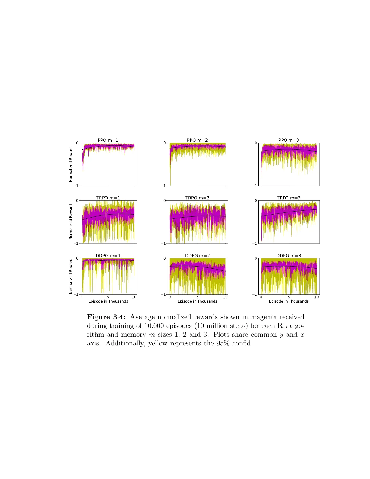
BOSTON UNIVERSITY GRADUA TE SCHOOL OF AR TS AND SCIENCES Dissertation FLIGHT CONTR OLLER SYNTHESIS VIA DEEP REINF OR CEMENT LEARNING b y WILLIAM FREDERICK K OCH I I I B.S., Univ ersit y of Rho de Island, 2008 M.S., Stev ens Institute of T ec hnology , 2013 Submitted in partial fulfillmen t of the requiremen ts for the degree of Do ctor of Philosoph y 2019 c 2019 b y WILLIAM FREDERICK K OCH I I I All righ ts reserv ed Appro v ed b y First Reader Azer Besta vros, PhD Professor of Computer Science Second Reader Renato Mancuso, PhD Assistan t Professor of Computer Science Third Reader Ric hard W est, PhD Professor of Computer Science Just flo w with the chaos... iv Ac kno wledgmen ts What an adv enture this has been. The past fiv e years ha v e b een some of the best y ears of my life. I hav e b een fortunate enough to ha v e the opportunities to w ork on pro jects and research that are dear to me, form life long relationships and trav el around the w orld. Its hard to imagine going through my PhD without the lov e and supp ort of m y family , friends, and colleagues who I would lik e to thank. I w ould like to start off b y thanking members of my committee Azer Bestavros, Ric h W est and Renato Mancuso. Azer, you hav e b een there for me since the b e- ginning. Y our wisdom and guidance has help ed shap e m y p ersp ectiv e on the world and ho w to step back and see the bigger picture. I appreciate your supp ort o v er the y ears and the partnerships and relationships y ou ha v e help ed me form. In the con text of research we hav e b een on quite a roller coaster ride, from cyb er security to fligh t con trol. Rich, thank y ou for alw a ys making me feel w elcome in y our lab. I will alw ays c herish our conv ersations and shared interests in racing. Y our energy has help ed me pursue an area of research that was intimidating and unkno wn. Renato, y ou could not ha v e joined BU at an y more perfect time. This researc h would not ha v e b een p os- sible without your supp ort and inv olv ement. Y our exp ertise in the field of real-time systems and fligh t con trol has pro vided in v aluable insigh t. W orking together has been a pleasure and will not b e forgotten. Additionally I would lik e to thank Manuel Egele who I w orked with for years conducting research in cyb er security b efore pursing my curren t researc h area in fligh t control systems. I ha ve learned a great deal from y ou and y ou hav e help ed shap ed me to b ecome a b etter researc her. My current researc h all b egan with drone racing. I would lik e to thank my friends and classmates Ethan Heilman, William Blair and Craig Einstein for the countless flying sessions and races ov er the years, esp ecially Ethan for first introducing the rest of us to the hobb y . These gatherings are what even tually led to the formation of v Boston Drone Racing (BDR), and it has b een incredible to see where it has evolv ed to to da y . With that I would like all the members of BDR, it truly has b een a blast and it is amazing to see ev ery one’s progression. On b ehalf of Boston Drone Racing w e are grateful to the BU CS department staff who ha ve alw ays help ed and supp orted us and Renato Mancuso for allo wing us to store racing equipment in the lab. Additionally I would lik e to thank my other classmates and friends Aanc hal Mal- hotra, Thomas Unger, Nikola j V olgushev and Sophia Y akoubov. No matter what we faced during our time at BU, we w ere going through it together. Our aw esome times living in Allston will never b e forgotten. Although we are now scattered across the glob e, the relationships we forged will alw ays remain close. I would lik e to thank m y friends Zack, Melissa, Da ve, Kat, Matt, Sydney , Drew and the URI crew for their supp ort ov er these years. Y ou hav e alw ays b een there for me, w e hav e exp erienced coun tless adven tures, you are family . Dad, thank you for your supp ort ov er the y ears. I will treasure our conv ersations w e had throughout my researc h ab out aeronautics. Flight definitely runs through our blo od. Mom, you hav e had unconditional lov e for me my entire life. Thank y ou for the scarifies you ha ve made for me ov er the years, and the opp ortunities you hav e giv en me. T o m y brothers Cole, Sp ence and Carter, I am so proud of y ou all, alw a ys follo w you dreams and passions in life. I will alw ays b e there for y ou. Randy and Ellen, I cannot b egin to thank you for your generosit y , kindness and hospitality ov er the years. Mark, Alissa, Shannon, Nic k, my nieces and nephew, I am so fortunate to ha ve you in my life. T o my wife Kristen, thank y ou for your kindness, encouragemen t, patience and lo ve. Y ou are my soul mate, b est friend and ro c k in m y life. Y ou hav e help ed me main tain a balance in life through this c haotic journey . No matter what is happ ening in life, y ou and Liam make me smile. I lov e the t wo of you with all of my heart. vi FLIGHT CONTR OLLER SYNTHESIS VIA DEEP REINF OR CEMENT LEARNING WILLIAM FREDERICK K OCH I I I Boston Univ ersit y , Graduate Sc ho ol of Arts and Sciences, 2019 Ma jor Professor: Azer Besta vros, PhD Professor of Computer Science ABSTRA CT T raditional con trol metho ds are inadequate in man y deploymen t settings in volving autonomous con trol of Cyb er-Ph ysical Systems (CPS). In suc h settings, CPS con- trollers m ust op erate and resp ond to unpredictable in teractions, conditions, or failure mo des. Dealing with suc h unpredictabilit y requires the use of executive and cogni- tiv e control functions that allo w for planning and reasoning. Motiv ated b y the sp ort of drone racing, this dissertation addresses these concerns for state-of-the-art flight con trol b y in vestigating the use of deep artificial neural netw orks to bring essential elemen ts of higher-lev el cognition to bear on the design, implemen tation, deplo yment, and ev aluation of low level (attitude) flight controllers. First, this thesis presen ts a feasibilit y analyses and results whic h confirm that neu- ral netw orks, trained via reinforcement learning, are more accurate than traditional con trol methods used by commercial uncrewed aerial vehicles (UA Vs) for attitude con trol. Second, armed with these results, this thesis rep orts on the dev elopmen t and release of an op en source, full solution stack for building neuro-fligh t con trollers. This stac k consists of a tuning framework for implemen ting training en vironments (GymF C) and firm w are for the w orld’s first neural net w ork supp orted fligh t con troller vii (Neurofligh t). GymFC’s no vel approac h fuses together the digital t winning paradigm with flight con trol training to pro vide seamless transfer to hardw are. Third, to trans- fer mo dels synthesized b y GymF C to hardware, this thesis rep orts on the to olc hain that has b een released for compiling neural netw orks into Neurofligh t, which can b e flashed to off-the-shelf micro con trollers. This to olc hain includes detailed pro cedures for constructing a m ulticopter digital t win to allow the researc h and dev elopmen t comm unity to synthesize flight con trollers unique to their own aircraft. Finally , this thesis examines alternativ e reward system functions as well as changes to the soft- w are environmen t to bridge the gap b et ween sim ulation and real w orld deploymen t en vironments. The design, ev aluation, and exp erimen tal work summarized in this thesis demon- strates that deep reinforcement learning is able to b e leveraged for the design and implemen tation of neural netw ork con trollers capable not only of main taining sta- ble flight, but also precision aerobatic maneuv ers in real world settings. As suc h, this work provides a foundation for developing the next generation of fligh t control systems. viii Con ten ts 1 In tro duction 1 1.1 Challenges Syn thesizing Neuro-controllers . . . . . . . . . . . . . . . 2 1.2 Scop e and Contributions . . . . . . . . . . . . . . . . . . . . . . . . . 4 1.2.1 T uning F ramework and T raining En vironment . . . . . . . . . 6 1.2.2 Digital Twin Dev elopment . . . . . . . . . . . . . . . . . . . 8 1.2.3 Fligh t Control Firmw are . . . . . . . . . . . . . . . . . . . . . 10 1.3 Structure . . . . . . . . . . . . . . . . . . . . . . . . . . . . . . . . . 12 2 Bac kground and Related W ork 13 2.1 History of Fligh t Control . . . . . . . . . . . . . . . . . . . . . . . . . 13 2.2 Quadcopter Fligh t Dynamics . . . . . . . . . . . . . . . . . . . . . . . 16 2.3 Fligh t Control for Commercial UA Vs . . . . . . . . . . . . . . . . . . 19 2.4 Fligh t Control Research in Academia . . . . . . . . . . . . . . . . . . 21 2.4.1 Fligh t Control via Reinforcement Learning . . . . . . . . . . . 23 2.5 T ransfer learning . . . . . . . . . . . . . . . . . . . . . . . . . . . . . 26 2.6 Digital Twinning . . . . . . . . . . . . . . . . . . . . . . . . . . . . . 30 3 Reinforcemen t Learning for UA V A ttitude Control 33 3.1 Bac kground and Related W ork . . . . . . . . . . . . . . . . . . . . . . 37 3.2 Reinforcemen t Learning Architecture . . . . . . . . . . . . . . . . . . 39 3.3 GymF Cv1 . . . . . . . . . . . . . . . . . . . . . . . . . . . . . . . . . 41 3.3.1 Digital Twin La yer . . . . . . . . . . . . . . . . . . . . . . . . 41 3.3.2 Comm unication Lay er . . . . . . . . . . . . . . . . . . . . . . 45 ix 3.3.3 En vironment Interface Lay er . . . . . . . . . . . . . . . . . . . 46 3.4 Ev aluation . . . . . . . . . . . . . . . . . . . . . . . . . . . . . . . . . 48 3.4.1 Setup . . . . . . . . . . . . . . . . . . . . . . . . . . . . . . . 48 3.4.2 Results . . . . . . . . . . . . . . . . . . . . . . . . . . . . . . . 51 3.4.3 Con tinuous T ask Ev aluation . . . . . . . . . . . . . . . . . . . 61 3.5 F uture W ork and Conclusion . . . . . . . . . . . . . . . . . . . . . . . 64 4 Neurofligh t: Next Generation Fligh t Control Firm ware 66 4.1 Bac kground and Related W ork . . . . . . . . . . . . . . . . . . . . . . 68 4.2 Neurofligh t Overview . . . . . . . . . . . . . . . . . . . . . . . . . . . 69 4.3 GymF Cv1.5 . . . . . . . . . . . . . . . . . . . . . . . . . . . . . . . . 71 4.3.1 State Represen tation . . . . . . . . . . . . . . . . . . . . . . . 72 4.3.2 Rew ard System . . . . . . . . . . . . . . . . . . . . . . . . . . 74 4.4 T o olchain . . . . . . . . . . . . . . . . . . . . . . . . . . . . . . . . . 77 4.4.1 Syn thesis . . . . . . . . . . . . . . . . . . . . . . . . . . . . . 78 4.4.2 Optimization . . . . . . . . . . . . . . . . . . . . . . . . . . . 79 4.4.3 Compilation . . . . . . . . . . . . . . . . . . . . . . . . . . . . 80 4.5 Ev aluation . . . . . . . . . . . . . . . . . . . . . . . . . . . . . . . . . 81 4.5.1 Firm ware Construction . . . . . . . . . . . . . . . . . . . . . . 81 4.5.2 Sim ulation Ev aluation . . . . . . . . . . . . . . . . . . . . . . 87 4.5.3 Timing Analysis . . . . . . . . . . . . . . . . . . . . . . . . . . 89 4.5.4 P ow er Analysis . . . . . . . . . . . . . . . . . . . . . . . . . . 92 4.5.5 Fligh t Ev aluation . . . . . . . . . . . . . . . . . . . . . . . . . 94 4.6 F uture W ork and Conclusion . . . . . . . . . . . . . . . . . . . . . . . 98 5 Aircraft Mo delling for In Silic o Neuro-fligh t Con troller Synthesis 100 5.1 GymF Cv2 . . . . . . . . . . . . . . . . . . . . . . . . . . . . . . . . . 103 5.1.1 Arc hitecture . . . . . . . . . . . . . . . . . . . . . . . . . . . . 104 x 5.1.2 User Pro vided Mo dules . . . . . . . . . . . . . . . . . . . . . . 108 5.2 Digital Twin Mo delling . . . . . . . . . . . . . . . . . . . . . . . . . . 111 5.2.1 Rigid Bo dy . . . . . . . . . . . . . . . . . . . . . . . . . . . . 111 5.2.2 IMU Mo del . . . . . . . . . . . . . . . . . . . . . . . . . . . . 114 5.2.3 Motor Mo del . . . . . . . . . . . . . . . . . . . . . . . . . . . 115 5.2.4 Exp erimen tal Metho dology . . . . . . . . . . . . . . . . . . . . 118 5.2.5 Exp erimen tal Results . . . . . . . . . . . . . . . . . . . . . . . 123 5.3 Sim ulation Stability Analysis . . . . . . . . . . . . . . . . . . . . . . 130 5.3.1 Measuring Stabilit y . . . . . . . . . . . . . . . . . . . . . . . . 133 5.3.2 Implemen tation . . . . . . . . . . . . . . . . . . . . . . . . . . 134 5.3.3 Stabilit y Results . . . . . . . . . . . . . . . . . . . . . . . . . 134 5.4 Neuro-fligh t Controller T raining Implemen tation . . . . . . . . . . . . 135 5.4.1 User Pro vided Mo dules . . . . . . . . . . . . . . . . . . . . . . 138 5.5 Ev aluation . . . . . . . . . . . . . . . . . . . . . . . . . . . . . . . . . 143 5.5.1 Neuro-Con troller Synthesis . . . . . . . . . . . . . . . . . . . . 144 5.5.2 Sim ulation Ev aluation . . . . . . . . . . . . . . . . . . . . . . 148 5.5.3 Neurofligh t Flight Ev aluations . . . . . . . . . . . . . . . . . . 152 5.5.4 Discussion . . . . . . . . . . . . . . . . . . . . . . . . . . . . . 157 5.6 Related W ork . . . . . . . . . . . . . . . . . . . . . . . . . . . . . . . 158 5.6.1 Fligh t Simulators and Aircraft Mo dels . . . . . . . . . . . . . 158 5.6.2 Prop eller Propulsion System Data . . . . . . . . . . . . . . . . 159 5.7 Conclusion and F uture W ork . . . . . . . . . . . . . . . . . . . . . . . 160 6 Conclusions 163 6.1 Summary of Con tributions . . . . . . . . . . . . . . . . . . . . . . . . 163 6.2 Op en Challenges and F uture W ork . . . . . . . . . . . . . . . . . . . 165 References 169 xi Curriculum Vitae 179 xii List of T ables 3.1 PPO h yp erparameters where ρ is linearly annealed o ver the course of training from 1 to 0. . . . . . . . . . . . . . . . . . . . . . . . . . . . 49 3.2 TRPO h yp erparameters. . . . . . . . . . . . . . . . . . . . . . . . . . 49 3.3 DDPG h yp erparameters. . . . . . . . . . . . . . . . . . . . . . . . . . 50 3.4 Rise time a verages from 3,000 command inputs p er configuration with 95% confidence. . . . . . . . . . . . . . . . . . . . . . . . . . . . . . 53 3.5 P eak a v erages from 3,000 command inputs p er configuration with 95% confidence. . . . . . . . . . . . . . . . . . . . . . . . . . . . . . . . . 53 3.6 Error a v erages from 3,000 command inputs p er configuration with 95% confidence. . . . . . . . . . . . . . . . . . . . . . . . . . . . . . . . . 54 3.7 Stabilit y av erages from 3,000 command inputs p er configuration with 95% confidence. . . . . . . . . . . . . . . . . . . . . . . . . . . . . . 54 3.8 Success and F ailure results for considered algorithms. The ro w high- ligh ted in blue refers to our best-p erforming learning agen t PPO, while the rows highlighted in y ellow corresp ond to the b est agents for the other t wo algorithms. . . . . . . . . . . . . . . . . . . . . . . . . . . 55 3.9 RL rise time ev aluation compared to PID of b est-p erforming agent. V alues rep orted are the a verage of 1,000 command inputs with 95% confidence. PPO m = 1 highligh ted in blue outp erforms all other agen ts, including PID con trol. Metrics highligh ted in red for PID con- trol are outpreformed b y the PPO agent. . . . . . . . . . . . . . . . . 55 xiii 3.10 RL p eak angular velocity p ercentage ev aluation compared to PID of b est-performing agent. V alues rep orted are the a verage of 1,000 com- mand inputs with 95% confidence. PPO m = 1 highlighted in blue outp erforms all other agen ts, including PID con trol. Metrics high- ligh ted in red for PID control are outpreformed by the PPO agent. . . 56 3.11 RL error ev aluation compared to PID of b est-p erforming agent. V al- ues rep orted are the av erage of 1,000 command inputs with 95% con- fidence. PPO m = 1 highlighted in blue outp erforms all other agents, including PID control. Metrics highlighted in red for PID con trol are outpreformed b y the PPO agent. . . . . . . . . . . . . . . . . . . . . 56 3.12 RL stability ev aluation compared to PID of b est-p erforming agent. V alues rep orted are the a verage of 1,000 command inputs with 95% confidence. PPO m = 1 highligh ted in blue outp erforms all other agen ts, including PID con trol. Metrics highligh ted in red for PID con- trol are outpreformed b y the PPO agent. . . . . . . . . . . . . . . . . 57 4.1 Comparison b et w een Iris and NF1 sp ecifications. . . . . . . . . . . . 83 4.2 PPO h yp erparameters where ρ is linearly annealed o ver the course of training from 1 to 0. . . . . . . . . . . . . . . . . . . . . . . . . . . . 85 4.3 P erformance metric for NN training v alidation. Metric is rep orted for eac h individual axis, along with the av erage. Low er v alues are b etter. 87 4.4 Con trol algorithm timing analysis. . . . . . . . . . . . . . . . . . . . . 89 4.5 Fligh t control task timing analysis. . . . . . . . . . . . . . . . . . . . 90 4.6 P ow er analysis of Neuroflight compared to Betaflight. . . . . . . . . . 94 4.7 Error metrics of the NN controller from 5 fligh t in the real world. Metrics are rep orted for each individual axis, along with the av erage. Lo wer v alues are b etter. . . . . . . . . . . . . . . . . . . . . . . . . . 95 xiv 4.8 Error metrics for simulation pla yback using NN con troller. Metric is rep orted for eac h individual axis, along with the av erage. Lo wer v alues are b etter. . . . . . . . . . . . . . . . . . . . . . . . . . . . . . . . . . 95 4.9 Error metrics for sim ulation playbac k using PID con troller. Metric is rep orted for eac h individual axis, along with the av erage. Lo wer v alues are b etter. . . . . . . . . . . . . . . . . . . . . . . . . . . . . . . . . . 96 5.1 Digital t win API. This table summarizes the topics and their corre- sp onding message v alues. Direction sp ecifies who is the publisher where → is a message published by the flight controller plugin and ← is a message published b y a sensor. . . . . . . . . . . . . . . . . . . . . . . 109 5.2 Normal PDF parameters for gyro noise mean ( η (ax ,µ ) ) and v ariance ( η (ax ,σ ) ) in degrees p er second. . . . . . . . . . . . . . . . . . . . . . . 123 5.3 Prop eller propulsion system parameters. . . . . . . . . . . . . . . . . 124 5.4 Prop eller propulsion system mo del constan ts. . . . . . . . . . . . . . 124 5.5 PPO h yp erparameters where ρ is linearly annealed o ver the course of training from 1 to 0. . . . . . . . . . . . . . . . . . . . . . . . . . . . 139 5.6 Sim ulation v alidation of p erformance metrics of NN con troller trained with p olicy using digital twin. Metrics are rep orted for eac h individual axis, along with the a verage. Lo wer v alues are b etter. . . . . . . . . . 148 5.7 Sim ulation v alidation of p erformance metrics of PID controller trained with p olicy using digital twin. Metrics are rep orted for eac h individual axis, along with the a verage. Lo wer v alues are b etter. . . . . . . . . . 149 5.8 Av erage error metrics of the NN controller from fligh ts in the real w orld trained with the digital t win. Metrics are rep orted for each individual axis, along with the a verage. Lo wer v alues are b etter. . . . . . . . . . 155 xv 5.9 Error metrics of simulation pla yback NN con troller trained with policy using digital t win. Metrics are rep orted for eac h individual axis, along with the a verage. Lo wer v alues are b etter. . . . . . . . . . . . . . . . 155 xvi List of Figures 1 · 1 FPV racing drone. . . . . . . . . . . . . . . . . . . . . . . . . . . . . 4 1 · 2 Neuro-flight controller solution stack. . . . . . . . . . . . . . . . . . . 5 2 · 1 Axis of rotation . . . . . . . . . . . . . . . . . . . . . . . . . . . . . . 16 2 · 2 Commands of a quadcopter. Red wide arro ws represent faster angular v elo cit y , while blue narrow arro ws represen t slow er angular velocity . F aster and slow er v elo cities are relativ e to when its net force is zero. 19 2 · 3 Deep RL architecture. . . . . . . . . . . . . . . . . . . . . . . . . . . 24 3 · 1 RL architecture using the GymF C environmen t for training in telligen t attitude fligh t controllers. . . . . . . . . . . . . . . . . . . . . . . . . 40 3 · 2 Overview of GymFCv1 environmen t arc hitecture. . . . . . . . . . . . 42 3 · 3 The Iris quadcopter in Gazeb o one meter ab o v e the ground. The b o dy is transparent to sho w where the center of mass is linked as a ball join t to the w orld. Arro ws represen t the v arious join ts used in the mo del. 43 3 · 4 Average normalized rew ards shown in magen ta received during training of 10,000 episo des (10 million steps) for each RL algorithm and memory m sizes 1, 2 and 3. Plots share common y and x axis. Additionally , y ellow represents the 95% confidence interv al and the blac k line is a t wo degree p olynomial added to illustrate the trend of the rew ards o ver time. . . . . . . . . . . . . . . . . . . . . . . . . . . . . . . . . . . . 52 xvii 3 · 5 Step response of b est trained RL agen ts compared to PID. T arget angular v elo cit y is Ω ∗ = [2 . 20 , − 5 . 14 , − 1 . 81] rad/s shown by dashed blac k line. Error bars ± 10% of initial error from Ω ∗ are shown in dashed red. . . . . . . . . . . . . . . . . . . . . . . . . . . . . . . . . 60 3 · 6 Step resp onse and PWM motor signals in microseconds ( µ s) of the b est trained PPO agent compared to PID. T arget angular velocity is Ω ∗ = [2 . 11 , − 1 . 26 , 5 . 00] rad/s shown by dashed black line. Error bars ± 10% of initial error from Ω ∗ are sho wn in dashed red. . . . . . . . . 61 3 · 7 Performance of PPO agent trained with episo dic tasks but ev aluated using a contin uous task for a duration of 60 seconds. The time in sec- onds at which a new command is issued is randomly sampled from the in terv al [0 . 1 , 1] and eac h issued command is maintained for a random duration also sampled from [0 . 1 , 1]. Desired angular velocity is sp eci- fied by the blac k line while the red line is the attitude trac ked b y the agen t. . . . . . . . . . . . . . . . . . . . . . . . . . . . . . . . . . . . 62 3 · 8 Close up of contin uous task results for PPO agen t with PWM v alues. 63 3 · 9 Resp onse comparison of a PID and PPO agen t ev aluated in con tin uous task en vironmen t. The PPO agent, how ev er, is only trained using episo dic tasks. . . . . . . . . . . . . . . . . . . . . . . . . . . . . . . . 63 4 · 1 Overview of the Neuroflight architecture. . . . . . . . . . . . . . . . . 71 4 · 2 Overview of the Neuroflight to olc hain. . . . . . . . . . . . . . . . . . 78 4 · 3 Iris simulated quadcopter compared to the NF1 real quadcopter. . . . 82 4 · 4 Flight in simulation (left) and in the real world (right). . . . . . . . . 83 4 · 5 Cumulativ e rew ards for each training episo de. . . . . . . . . . . . . . 86 xviii 4 · 6 Simulation v alidation of trained NN in GymFCv1.5 training en viron- men t. Actual aircraft angular velocity is represented by the red line, while the desired angular velocity is the dashed blac k line. Con trol signal and motor v elo cit y is also shown. . . . . . . . . . . . . . . . . 88 4 · 7 Flight test log demonstrating Neuroflight trac king a desired angular v elo cit y in the real world compared to in simulation. Maneuvers during this fligh t are annotated. . . . . . . . . . . . . . . . . . . . . . . . . 91 4 · 8 Performance comparison of the NN con troller versus a PID con troller trac king a desired angular v elo cit y in simulation to execute the Split-S and roll aerobatic maneuv ers. . . . . . . . . . . . . . . . . . . . . . . 93 5 · 1 Instance of GymF Cv2 arc hitecture for syn thesizing RL-based fligh t con troller. . . . . . . . . . . . . . . . . . . . . . . . . . . . . . . . . . 103 5 · 2 Digital twin of NF1 compared to real quadcopter. . . . . . . . . . . . 112 5 · 3 Dynamometer diagram. . . . . . . . . . . . . . . . . . . . . . . . . . . 118 5 · 4 Instance of GymFCv2 architecture for dyno v alidation. . . . . . . . . 121 5 · 5 Gyro Noise . . . . . . . . . . . . . . . . . . . . . . . . . . . . . . . . 126 5 · 6 Step resp onse of motor mo del compared to real motor. . . . . . . . . 127 5 · 7 Throttle curve. . . . . . . . . . . . . . . . . . . . . . . . . . . . . . . 127 5 · 8 Throttle ramp measurements. . . . . . . . . . . . . . . . . . . . . . . 129 5 · 9 Prop eller co efficien ts . . . . . . . . . . . . . . . . . . . . . . . . . . . 131 5 · 10 Motor mo del constan ts. . . . . . . . . . . . . . . . . . . . . . . . . . . 132 5 · 11 ODE physics engine with 2 ms step size (500Hz). . . . . . . . . . . . . 136 5 · 12 ODE physics engine with 1 ms step size (1kHz). . . . . . . . . . . . . 136 5 · 13 ODE physics engine with 500 µs step size (2kHz). . . . . . . . . . . . 137 5 · 14 D AR T physics engine with 1 ms step size (1kHz). . . . . . . . . . . . 137 5 · 15 PDF of Pilot Command Inputs . . . . . . . . . . . . . . . . . . . . . 142 xix 5 · 16 PPO training v alidation. . . . . . . . . . . . . . . . . . . . . . . . . . 146 5 · 17 Implemen tation of GymF Cv2 for PID control tuning and SITL testing. 147 5 · 18 Step resp onse comparison b et w een PPO-based fligh t controller, and PID fligh t controller. . . . . . . . . . . . . . . . . . . . . . . . . . . . 150 5 · 19 Zoomed in comparison b et ween PPO-based flight controller, and PID fligh t controller. . . . . . . . . . . . . . . . . . . . . . . . . . . . . . . 151 5 · 20 Fligh t en velope of PID flight controller. . . . . . . . . . . . . . . . . . 152 5 · 21 Fligh t en velope of neuro-flight controller. . . . . . . . . . . . . . . . . 153 5 · 22 Fligh t test for neuro-fligh t controller synthesized with digital twin. . . 156 5 · 23 Zoomed in p ortion of a roll b eing executed. . . . . . . . . . . . . . . . 156 xx List of Abbreviations API . . . . . . application programming in terface DDPG . . . . . . Deep Deterministic Policy Gradien t DOF . . . . . . degrees of freedom ESC . . . . . . electronic sp eed controller F C . . . . . . fligh t controller FPV . . . . . . first p erson view IMU . . . . . . inertial measurement unit HITL . . . . . . hardw are in the lo op NF . . . . . . Neurofligh t NN . . . . . . neural net work PPO . . . . . . Pro ximal P olicy Optimization PWM . . . . . . pulse width mo dulation RL . . . . . . reinforcemen t learning RX . . . . . . receiver SITL . . . . . . soft ware in the lo op TRPO . . . . . . T rust Region Policy Optimization UA V . . . . . . uncrew ed aerial vehicle VTX . . . . . . video transmitter xxi List of Sym b ols a agen t action b n umber of prop eller blades B thrust factor C T , C Q thrust and torque co efficien t D degrees of freedom e angular v elo cit y error e φ , e θ , e ψ angular v elo cit y error elements F force F min , F max min and max c hange in rotor force H rotor v elo cit y transfer function J adv ance ratio K T , K Q thrust and torque constan t K P , K I , K D PID gains K v motor constan t l m ulticopter arm length M aircraft actuator coun t r reinforcement learning reward S aircraft state t time in seconds T thrust T desired throttle b T actual throttle u control signal U T , U φ , U θ , U ψ aero dynamic affect for thrust, roll, pitch and ya w x neural netw ork input y neural net work output Ω angular v elo cit y Ω φ , Ω θ , Ω ψ angular v elo cit y axis elements Ω ∗ desired angular v elo cit y η (ax ,µ ) mean gyro noise for axis ax η (ax ,σ ) v ariance of gyro noise for axis ax φ, θ , ψ roll, pitc h and ya w axis τ torque xxii ρ air mass density ω angular velocity array for each rotor ω i angular v elo cit y of rotor i π p olicy γ PPO discount λ GAE parameter δ simulation stability metric xxiii 1 Chapter 1 In tro duction Recen t adv ances in science and engineering, coupled with affordable pro cessors and sensors, has led to an explosive growth in Cyb er-Ph ysical Systems (CPS). Softw are comp onen ts in a CPS are tightly in tertwined with their physical op erating en viron- men t. This soft ware reacts to changes in its environmen t in order to con trol ph ysical elemen ts in the real world. Typically a CPS incorporates a control algorithm to reac h a desired state, for example to control the mov emen t of a rob otic arm, navigate an autonomous automobile or to stabilize an uncrewed aerial v ehicle (UA V) during flight. A CPS’s en vironment is inherently complex and dynamic, from the degradation of the physical elements o ver the life time of the system, to its op erating environ- men t (w eather, external disturbances, electrical noise, etc.). T o achiev e optimal con- trol in these environmen ts, that is to derive a control la w that has b een optimized for a particular ob jectiv e function, one requires sophisticated con trol strategies. Al- though control theory has a ric h history dating back to the 19th century (Maxwell, 1868), traditional con trol metho ds hav e their limitations. Primarily they lac k exec- utiv e functions and cognitive control that allow for memory , learning and planning. Suc h functionality in a con troller is fundamental for the safet y , reliability and p er- formance of next generation CPS’s that will b e closely integrated into our lives. F or example, these con trollers m ust ha ve the in tellectual capacit y to instan taneously react to catastrophes as w ell as b eing able to predict and mitigate future failures. Ov er the last decade artificial neural net w ork (NN) based controllers (neuro- 2 con trollers), for use in a CPS, ha ve b ecome practical for con tinuous control tasks in the real world. A NN is a mathematical mo del mimic king a biological brain ca- pable of approximating an y con tinuous function (Cyb enk o, 1989). Unlik e traditional con trol metho ds, they pro vide the essen tial comp onen ts for ac hieving high order cog- nitiv e functionality . Each neuron (no de) connection of the NN is asso ciated with a n umerical w eight that em ulates the strength of the neuron. T o ac hieve the desired p erformance, these weigh ts are tuned through a pro cess called training. P art of the success of NN based con trollers for con tin uous tasks can b e attributed to exp onen tial progress in the field of deep reinforcement learning (RL). Deep RL is a mac hine learning paradigm for training deep NNs. The term deep refers to the width of the NN’s architecture. As control problems increase in complexity t ypically the width must also increase. RL allo ws the NN to in teract with their op erating en vironment (typically done in a simulation) to iterativ ely learn a task. The NN (commonly referred to as the agent) receives a n umerical rew ard indicating ho w w ell they p erformed the task. Reward engineering is the pro cess of designing a rew ard system in order reinforce the desired b ehavior of the agent (Dewey , 2014). The RL training algorithm’s ob jectiv e is to maximize these rewards ov er time. Once the NN has b een trained, it can b e transferred to execute on hardw are in the real w orld. This has b ecome practical in recent y ears due to adv ancemen ts in size, weigh t, p ow er and cost (SW aP-C) optimized electronics. 1.1 Challenges Syn thesizing Neuro-con trollers Although neuro-con trollers trained in simulation via RL ha v e enormous p oten tial for the future CPS, there are still a n umber of challenges that m ust b e addressed. P articularly , ho w do we reach a desired level of p erformance during training in sim- ulation and successfully transfer the trained mo del into hardw are to achiev e similar 3 p erformance in the real world. P erformance. A controller is designed with a sp ecific n um b er of p erformance goals in mind depending on the application. The primary goal is to accurately con trol the physical system within some predefined level of tolerance that is usually go verned b y the underlying system. F or a rob otic arm this may refer to the precision of the mo vemen ts, or for a UA V attitude controller how w ell the angular v elo cit y is able to b e controlled. Ho wev er there are typically other sub-goals the con troller should b e optimized for such as reducing energy consumption, and minimizing con trol output oscillations. Because of a NNs blac k b o x nature, which can consist of thousands if not millions of connections, achieving the desired level of p erformance is not as straigh t forw ard as developing a transfer function for a traditional con trol system for whic h the step resp onse characteristics can b e calculated. A num b er of factors affect the controllers p erformance such as the NN arc hitecture, RL training algorithm, h yp erparameters, and the rew ard function. The rew ard function is sp ecific to the CPS con trol task, and the desired p erfor- mance goals. The rewards must enco de the desired p erformance we wish the agent to obtain. T o reach a desired level of control accuracy the reward system must in- clude a representation of the error, that is the difference b etw een the curren t state and the desired state. Ho wev er as the p erformance goals increase in complexit y , it b ecomes increasingly more difficult to balance these goals to obtain the desired lev el of p erformance. T ransferabilit y . The ultimate goal is to b e able to syn thesize a neuro-con troller in simulation and transfer it seamlessly to hardw are to be used in the real w orld. Although in simulation w e ma y b e able to ac hieve a desired level of p erformance, it is difficult to obtain the same lev el of p erformance in the real w orld. This is due to the 4 Propeller Motor FC/ESC VTX Battery Camera Radio RX Figure 1 · 1: FPV racing drone. difference b et w een the tw o environmen ts commonly referred to as the r e ality gap . In sim ulation the fidelit y of the environmen t and the CPS mo del b oth hav e an impact on the transferabilit y . The w orld is a complex place, increasing simulation fidelity and mo delling all of the dynamics in simulation is c hallenging and computationally exp ensiv e. Thus prioritizing mo delling parameters and deriving strategies to aid in the transferability is required. It is critical to address the realit y gap in order to pro vide seamless transfer of the controller from sim ulation to hardware while still gaining the desired lev el of p erformance. 1.2 Scop e and Con tributions Motiv ation for this work has b een driven b y drone racing. The sp ort of drone racing demands the highest level of flight p erformance to maintain a comp etitiv e edge. In drone racing, a UA V is remotely piloted by first-p erson-view (FPV). FPV provides an immersed flying exp erience allo wing the UA V to b e piloted from the p erspective as if you were onboard the aircraft. This is accomplished by transmitting the video 5 Flight Contr ol Firmwar e T r aining Envir onment Digital T win Figure 1 · 2: Neuro-fligh t con troller solution stack. feed of an onboard camera to goggles with an embedded monitor worn b y the pilot. The pilot man ually con trols the angular velocity (attitude) of the aircraft and mixes in throttle to achiev e translational mov emen ts. A t ypical FPV equipp ed racing drone is pictured in Fig. 1 · 1. A racing drone is an in teresting CPS for studying con trol as they are capable of high speeds and aggressiv e maneuv ers. F urthermore the con troller is exp osed to a num b er of nonlinear dynamics. Using a racing drone as our exp erimen tal platform we study the aforementioned c hallenges for synthesizing neuro-con trollers. In resp onse to the study , the main con- tribution of this dissertation is a full solution stac k depicted in Fig. 1 · 2 for syn thesizing neuro-fligh t con trollers. This stac k includes a sim ulation training en vironmen t, digital t win mo delling metho dology , and flight con trol firmw are. Throughout this dissertation w e synthesize neuro-controllers for the quadcopter aircraft, how ev er the training methods describ ed in this work are generic to most space and aircraft. Specifically our contributions are in training low level attitude con trollers. Previous w ork (Kim et al., 2004; Abb eel et al., 2007; Hw angb o et al., 6 2017; dos Santos et al., 2012; P alossi et al., 2019) has fo cused on high lev el na vigation and guidance tasks, while it has remained unkno wn how w ell these type of con trollers p erform for low level control. This dissertation is scop ed to synthesizing neuro-con trollers offline in sim ulation. This is a precursor for practical deplo yment as the controller m ust hav e initial knowl- edge of ho w to achiev e stable fligh t. W e pro vide an initial study of these type of con- trollers and publish op en source softw are and framew orks for researc hers to progress their p erformance. F or neuro-con trollers to b e adopted in the future we b elieve a h ybrid solutions that incorp orates online learning metho ds to compensate for un- mo delled dynamics in the sim ulation en vironment will b e required. How ev er as the sa ying go es, one m ust learn to walk b efore one can run. Giv en the capacit y and p oten tial of NNs, we b eliev e they are the future for dev el- oping high performance, reliable fligh t con trol systems. Our con tributions and impact are predominately in the dev elopment and release of op en source soft ware allo wing others to build off of our w ork to adv ance the progression in intelligen t flight con- troller design. W e will now briefly summarize the contributions of eac h item in the solution stac k. 1.2.1 T uning F ramework and T raining Environmen t Most control algorithms are asso ciated with a set of adjustable parameters that m ust b e tuned for their sp ecific application. T uning a fligh t controller in the real w orld is a time consuming task and few systematic approac hes are op enly av ailable. Sim ulated en vironments, on the other hand, are an attractive option for dev eloping automated systematic metho ds for tuning. They are cost effective, run faster than real time, and easily allo w softw are to automate tasks. The b enefits of a sim ulated en vironment for tuning flight con trollers is not unique to RL-based con trollers, but also applies to traditional controllers as well. In the 7 con text of neuro-controllers, training is just the pro cess of tuning the NNs weigh ts. In summary this dissertation makes the following con tributions in controller tuning and RL training en vironments. GymF C: The first item in our solution stac k is an op en source tuning frame- w ork for synthesizing neuro-flight controllers in simulation called GymFC. GymFC w as originally developed as an RL training environmen t for synthesizing attitude fligh t con trollers. The initial environmen t architecture is introduced in Chapter 3 and has b een published in (Ko c h et al., 2019b). Since the pro jects release GymFC has matured into a generic univ ersal tuning framew ork based on feedbac k receiv ed from the comm unity . Revisions to GymFCv1, discussed in Chapter 5, increase user flexibilit y pro viding a framew ork to pro vide custom rew ard systems and aircraft mod- els. Additionally GymF C is no longer tied to an RL environmen t but no w op ens up the p ossibilities for other optimization algorithms to tune traditional controllers. In Chapter 5 we demonstrate the mo dular design of the framew ork by implementing a dynamometer for v alidating motor models in sim ulation, and a PID con troller tuning system. Our goal with GymFC is to pro vide the researc h communit y a standardized w ay for tuning fligh t con trollers in sim ulation. The source co de is av ailable at (Ko c h, 2018a). Fligh t con trol rew ard system: In the con text of RL-based fligh t con trollers the training en vironment must pro vide the agent with a reward they are doing the right thing. This dissertation shows the progression of our reward system developmen t to syn thesize accurate controllers and address c hallenges transferring controllers to the real w orld. In Chapter 3 w e introduce rewards to minimize error whic h has also b een published in (Ko c h et al., 2019b). F rom exp erimen tation we find in Chapter 4 that additional rewards are necessary in order to transfer the trained p olicy into hardw are whic h also app ear in (Ko c h et al., 2019a). As the accuracy of our aircraft model 8 con tinued to increase we fine tuned the reward system in Chapter 5 to decrease error. RL ev aluation: The field of RL is progressing rapidly and a n um b er of algorithms ha ve b een prop osed for contin uous control tasks. The RL algorithm can b e though t of as the NN tuner. It determines how the NN weigh ts are up dated dep ending on the agen ts curren t, and past interactions with the en vironmen t and rew ards receiv ed. This dissertation do es not introduce new RL algorithms but instead uses off-the-shelf implemen tations for the purp ose of synthesizing fligh t con trollers. Specifically this dissertation mak es its con tribution in the p erformance ev aluation of several state-of- the-art RL algorithms, including Deep Deterministic Policy Gradient (DDPG) (Lilli- crap et al., 2015), T rust Region P olicy Optimization (TRPO) (Sc hulman et al., 2015), and Pro ximal P olicy Optimization (PPO) (Sc h ulman et al., 2017). These results w ere first published in (Ko c h et al., 2019b). 1.2.2 Digital Twin Developmen t Ev ery aircraft is unique in its o wn wa y . Off the assembly line, accumulation of tolerances of each individual part from the manufacturing process results in a sligh tly differen t aircraft. In some cases p erformance betw een the same parts, suc h as sensors, can v ary greatly (Miglino et al., 1995). Once an aircraft is put in to service, they con tinue to diverge from their initial state as they age. T o maximize p erformance, a con troller w ould ideally b e syn thesized uniquely for eac h individual aircraft, at least in the scop e of offline training strategies. T o syn- thesize this con troller in simulation, what we need is a digital replica, or digital twin of the aircraft. A digital t win is a relatively new paradigm, generic to digitizing an y CPS which resides in an ultra high fidelity sim ulator. Once the CPS is put in to ser- vice, it is kept in sync hronization with its digital twin through the collection of state information from its senors. T ypical use cases for the digital twin are for analytics, design and forecasting failures. 9 This w ork is the first to fuse together digital t winning concepts for neuro-flight con troller training. In con trast, previous work has primarily used a mathematical mo del of the UA V (Hwangbo et al., 2017; W aslander et al., 2005; Kim et al., 2004; Abb eel et al., 2007) rather than a physics sim ulator. In summary we make the follo wing contributions in digital twinning. Multicopter Digital Twin Developmen t Pro cesses: Most flight con trol re- searc h p erformed in sim ulation use prebuilt aircraft models from Gazeb o (Ko enig and Ho ward, 2004) or PX4 (Meier et al., 2015) as they are readily a v ailable. In Chapter 3 for our initial feasibilit y analysis, w e also to ok this approach using the Iris quadcopter (iri, 2018) mo del pro vided by Gazeb o. W e improv ed the motor mo d- els to more accurately reflect the motors used by our real quadcopter in Chapter 4. Lastly in Chapter 5 w e provide our metho dology for creating a digital t win from the ground up and apply these pro cesses to create a digital twin of our custom built racing quadcopter. Our no vel dynamometer for iden tifying parameters of our propulsion system re- purp oses the avionics to capture the electronic dynamics that would b e exp erienced during flight which cannot otherwise b e captured from commercial dynamometers. This results in a higher fidelity motor mo del whic h enco des dynamics suc h as p o w er deliv ery from the electronic sp eed con troller (ESC) and control signal latency . Our con tributions are in the initial construction of the digital t win, w e do not main tain sync hronization with the twin after the aircraft is deploy ed in this work. Although our dev elopment is sp ecific our quadcopter, these pro cesses are applicable to an y multicopter. Propulsion System Mo dels: The p erformance capabilities of a m ulticopters propulsion system (motor and propeller pair) hav e a large influence in the ov erall p erformance of the aircraft. This work builds up on the softw are in the lo op (SITL) 10 motor mo dels dev elop ed by the PX4 firm ware pro ject (p x4, 2019). These mo dels ha ve been p orted to GymFC and w e ha v e in tro duced additional dynamics to increase realism suc h as motor resp onse and throttle curv e mapping. These mo dels hav e b een made op en source av ailable from (Ko c h, 2019a). Sim ulation Stabilit y Analysis: Multicopters (particular those found in racing) are capable of achieving high angular v elo cities, which induce large cen trip etal forces. Under certain circumstances this can result in the digital twin b ecoming unstable in sim ulation. In this w ork w e discuss the conditions in whic h instabilities can o ccur. W e also prop ose an algorithm for measuring sim ulation stability and ha ve included an implementation with GymFC (Ko c h, 2018a). Using this soft ware we p erform an analysis of our digital t win. 1.2.3 Fligh t Control Firmw are Common approac hes for deplo ying a neuro-controller to a UA V is to use a companion computer and run the NN in user space. How ev er this is usually only suitable for slo wer than real-time applications that do not hav e strict deadlines and the UA V can p ermit the size, and weigh t of the additional hardware. Companion computers are t ypically used for high level control tasks such as na vigation and guidance in flight con trol systems whic h need the additional computational resources but ha v e a slo wer con trol lo op in comparison to the lo w level stability control. T o meet con trol lo op timing requirements, UA Vs curren tly use micro con trollers to execute the real-time task of low lev el flight con trol. How ev er there previously did not exist solutions for deploying neuro-controllers to micro con trollers let alone a fligh t control firmw are that supp orted neuro-controllers. T o ev aluate our neuro-con trollers trained in simulation in the real world it w as first necessary for us to develop metho ds for compiling a NN to run on a micro con troller. With these metho ds established w e developed the flight control firm ware Neuroflight 11 to supp ort neuro-attitude flight con trollers. The results from this work first app eared in (Ko c h et al., 2019a). In summary , this dissertation makes the following con tribu- tions in the area of fligh t control firmw are. Neurofligh t: Prior to this work, every op en source flight control firmw are av ail- able used PID control (Eb eid et al., 2018). In this w ork we hav e created the world’s first op en source NN supp orted flight control firm ware for UA Vs, Neuroflight. The firm ware pro vides the communit y with a platform to exp erimen t with their own trained p olicies and further progress adv ancements in field of fligh t con trol. The source co de is av ailable from (Ko c h, 2018b). T o olc hain: The target hardw are for most UA V fligh t con trol firm ware is sig- nifican tly resource constrained. The off-the-shelf micro con trollers supp orted by the family of high p erformance drone racing firm w ares only consists of 1MB of flash memory , 320KB of SRAM and an ARM Cortex-M7 pro cessor with a clo c k sp eed of 216MHz (STM, 2018). This dissertation prop oses a toolchain to allow NNs to b e compiled to run on off-the-shelf micro con trollers with hard floating p oin t arithmetic. The impact of this to olc hain reac hes b eyond flight control for UA Vs and op ens up the p ossibilities of using neuro-control for other CPS’s in resource constrained en vi- ronmen ts. Fligh t P erformance Ev aluation: In the context of lo w level attitude con trol, this w ork pro vides the first ev aluation of a neuro-controller trained in simu lation and transferred to hardware to fly in the real world. Our timing analysis reveals the NN-based attitude con trol task is able to execute at ov er 2kHz on an Arm Cortex-M micro con troller. W e demonstrate our training environmen t, and rew ard functions are capable of synthesizing controllers with remark able p erformance in the real world. Our real world flight ev aluations v alidate these con trollers are capable of stable flight and the execution of aerobatic maneuv ers. 12 1.3 Structure In summary , the remainder of this dissertation is organized as follows. In Chap- ter 2 w e discuss imp ortan t bac kground information and related work p ertinen t to syn thesizing neuro-based flight con trollers. In Chapter 3 w e present our flight con trol training en vironment GymFC and pro vide a feasibility analysis on whether neuro- fligh t controllers can accurately pro vide attitude con trol in simulation. T o iden tify if the synthesized controllers can achiev e stable flight in the real world we presen t our firm ware, Neurofligh t and its accompanying to olc hain in Chapter 4. W e prop ose our digital twin dev elopment metho dology in Chapter 5 and in tro duce our revisions to GymF C to supp ort training of arbitrary aircraft mo dels. Finally in Chapter 6 we conclude with our final remarks and future w ork. 13 Chapter 2 Bac kground and Related W ork In this chapter w e discuss bac kground concepts and related w ork. W e b egin in Sec- tion 2.1 with the history and evolution of fligh t control for fixed wing aircraft leading up to the rise of the quadcopter. In Section 2.2 we provide an ov erview of quad- copter flight dynamics and review flight control systems found in commercial UA Vs in Section 2.3. In Section 2.4 we discuss flight control researc h b eing conducted in academia and the trend tow ards in telligent control systems. In Section 2.4.1 w e em- phasize the academic researc h related to deep reinforcemen t learning in the con text of fligh t control. T o successfully transfer mo dels from sim ulation to hardware a num ber of strategies ha ve b een prop osed whic h w e review in Section 2.5. Lastly we provide an ov erview of digital twinning in Section 2.6 particularity in the context of fligh t con trol. 2.1 History of Fligh t Con trol Aviation has a ric h history in fligh t con trol dating bac k to the 1960s. During this time sup ersonic aircraft w ere being dev elop ed whic h demanded more sophisticated dynamic fligh t con trol than what a linear con troller could pro vide. Gain sc heduling (Leith and Leithead, 2000) was dev elop ed allowing multiple linear controllers of differen t configurations to be used in designated operating regions. This ho w ever w as inflexible and insufficient for handling the nonlinear dynamics at high sp eeds but pav ed wa y for adaptiv e control. 14 During the 1950s there was a p erio d know as the br ave er a in which v arious adaptiv e con trol tec hniques w ere tested with little time b etw een conception and im- plemen tation. The lack of theoretical analysis and guaran tees resulted in fatalities most notably in the X-15 crash (Ho v akim y an et al., 2011). Ev en tually this led to the dev elopmen t of Mo del Reference Adaptiv e Control (MRA C) (Whitaker et al., 1958) which introduced a reference mo del sp ecifying the desired p erformance of the con troller during adaptation. A reference mo del usually consists of the transient re- sp onse characteristics such as rise time, setting time and steady state error. How ev er early developmen ts of MRA C did not hav e stabilit y guaran tees during adaptation. It was not un til later that MRAC used the Ly apunov function for stability ( ˚ Astr¨ om and Wittenmark, 2013). T o improv e up on tuning challenges found in MRA C, L 1 w as prop osed which includes a lo wpass filter to decouple the rate of adaptation and robustness. An L 1 con trol system was tested in the U.S. Air F orce’s VIST A F-16 aircraft (F arha, 2016). Ho wev er there has b een considerable debate in the con trol comm unity due to tw o rebuttal pap ers questioning the true b enefits of L 1 adaptiv e con trol (Black et al., 2014). There has b een a trend tow ards using artificial in telligence for adaptiv e control in fixed wing crewed aircraft to comp ensate for the nonlinear aircraft dynamics, and uncertain ties. Sp ecifically the use of artificial NNs whic h provide capabilities that are b ey ond that of traditional con trol suc h as their abilit y to learn and approximate an y function. F or an introduction to NNs with applications to con trol w e refer to (Hagan and Dem uth, 1999). W ork pro vided b y (Kim et al., 1993) sought to create a single con troller v alid throughout the entire fligh t env elop e to remo ve the need for gain sc heduling. The use of nonlinear con trollers such as feedbac k linearization are an attractive option as they are able to transform the nonlinear system into an equiv alen t linear representation. 15 Once in a linear representation a linear controller, such as PID or linear quadratic Gaussian (LQG) can b e used. How ev er feedbac k linearization requires a mo del of the aircraft which can con tain errors. T o dev elop an aircraft mo del, the authors utilized a NN which is first trained offline using mathematical mo dels, and then fine tuned, online using a second NN to comp ensate for any mo del errors. Another interesting con tribution to this work was the use of the circle theorem (Zames, 1966) as a wa y to b ound the stability of this controller even in the presence of the NNs. The In telligent Flight Control System (IFCS) pro ject lead b y NASA was created to inv estigate the capabilities of NNs for adaptive con trol, with a fo cus in pro viding stabilit y during failure (Williams-Ha yes, 2005). F ailure in this work is scop ed to mal- functioning of the con trol surfaces. The pro ject’s test aircraft is a highly mo dified F-15; ho wev er this work only rep orts sim ulation results. Simulation results demon- strate the NN is able to restore the aircraft to a stable state after the o ccurrence of failure, in less time and smo other than without the presence of the NN. Starting in 2006 real flight tests began (Smith et al., 2010). During these test fligh ts, tw o failures w ere em ulated, lo cking of the left stabilator and change to the baseline angle of at- tac k of the canard (a small forw ard wing). Ov erall the test pilots rep orted impro ved handling with the NN enabled during failure. These results sho w a promising future for these t yp e of con trollers. As a result of the significant cost reduction for sensors and small-scale embedded computing platforms ov er the course of the last couple decades, UA Vs, particular- it y quadcopters, hav e surged in p opularit y . Due to their unique complex dynamics quadcopters hav e their own set of c hallenges related to flight con trol. Ho wev er w e are seeing similar patterns in the progress of flight con trol for UA Vs as we ha ve seen for fixed wing crewed aircraft. Although this dissertation’s fo cus is in the dev elopment of flight con trollers for quadcopters, nonetheless the ma jorit y of what is discussed is 16 Z X Y ψ θ φ Figure 2 · 1: Axis of rotation applicable to most m ulticopter configurations and fixed wing aircraft as well. 2.2 Quadcopter Fligh t Dynamics Before w e can discuss the sp ecifics of flight control p ertaining to the quadcopter aircraft it is necessary to understand some basics of their dynamics. A quadcopter is an aircraft with four (quad) motors using a prop eller propulsion system. It has six degrees of freedom (DOF), three rotational and three translational as depicted in Fig. 2 · 1. Throughout this dissertation w e will use the motor ID and order referenced in this figure, starting at index one, to b e consisten t with the or- dering used to configure our flight con trol firm ware, while the subscript used in the mathematical notation b egins with zero. W e indicate with ω i , i ∈ 0 , . . . , M − 1 the rotation sp eed of eac h rotor where M = 4 is the total n umber of motors for a quad- copter. These ha ve a direct impact on the resulting Euler angles φ, θ , ψ , i.e., roll, pitc h, ya w resp ectively and translation in each x , y , and z direction. The aero dynamic effect that eac h ω i pro duces dep ends up on the configuration of the motors. The motor configuration ( i.e., lo cation of eac h motor) can ha v e a significan t affect in fligh t p erformance dep ending on the distance the motors are from 17 eac h axis of rotation. In tuitively the greater the distance the motor is from the axis of rotation the more torque will b e required to tra v el along this arc compared to when a motor is moun ted closer to the axis. In the con text of classical mechanics, torque is defined as τ = l × F where l is the length of the lever and F is the applied force. T ranslated to a quadcopter, each motor and prop eller pair generates a force F at some distance l from the axis of rotation. The most p opular configuration is an X configuration, depicted in Fig. 2 · 1 whic h has the motors moun ted in an X formation relativ e to what is considered the fron t of the aircraft. This configuration pro vides more stabilit y compared to a + configuration whic h in contrast has its motor configuration rotated an additional 45 ◦ along the z- axis. This is due to the differences in torque generated along each axis of rotation in resp ect to the distance of the motor from the axis. Additionally the X configuration is a more practical arrangemen t for mounting cameras used for navigation. F or a + configuration the distance, in relation to pitch, is equiv alent to the dis- tance of the arm l . An X configuration with the same arm length l has a distance from the axis l × cos ( π / 4) resulting in less torque required. A decrease in the arm length pro vides increased resp onsiv eness. F urthermore the motor rotation in a + con- figuration is in the same direction along an axis of rotation leading to less stability than an X configuration. Based on these dynamics, frames are optimized dep ending on their application. F or example racing frames are often str etche d such that the distance b et ween motors 3 and 4, and motors 1 and 2, are at a greater distance than b et w een motors 1 and 3, and motors 2 and 4. This results in less torque along the roll axis pro viding a more resp onsiv e aircraft for p erforming turns. The aerodynamic affect U that eac h rotor speed ω i has on thrust and Euler angles, 18 is giv en by: U T = B ( ω 2 0 + ω 2 1 + ω 2 2 + ω 2 3 ) (2.1) U φ = B ( ω 2 0 + ω 2 1 − ω 2 2 − ω 2 3 ) (2.2) U θ = B ( ω 2 0 − ω 2 1 + ω 2 2 − ω 2 3 ) (2.3) U ψ = B ( ω 2 0 − ω 2 1 − ω 2 2 + ω 2 3 ) (2.4) where U T , U φ , U θ , U ψ is the thrust, roll, pitch, and y aw effect resp ectively , while B is a thrust factor that captures prop eller geometry and the motor configuration. The torque τ B applied to the aircraft is the torque applied to each axis φ, θ , ψ for roll, pitc h, ya w resp ectively . The mo del dev elop ed by (Luukk onen, 2011; Bouabdallah et al., 2004) mo dified for X configuration as, τ B = τ φ τ θ τ ψ = l cos ( π/ 4) B ( ω 2 0 + ω 2 1 − ω 2 2 − ω 2 3 ) l cos ( π/ 4) B ( ω 2 0 − ω 2 1 + ω 2 2 − ω 2 3 ) P M − 1 i =0 τ M i (2.5) where τ M i is the torque of eac h motor. T o p erform rotational mov emen t the v elo cit y of eac h rotor is manipulated accord- ing to the relationship expressed in Eq. 2.2 Eq. 2.3, Eq. 2.4 and as illustrated in Fig. 2 · 2. F or example, to roll right (Fig. 2 · 2h) more thrust is deliv ered to motor 3 and 4 ( i.e., ω 2 > ω 0 and ω 3 > ω 1 ). How ev er ya w is not ac hieved directly through difference in thrust generated by the rotor as roll and pitch are, but instead through a difference in torque generated b y the v elo cit y of the rotors. F or example, as shown in Fig. 2 · 2b, higher rotational sp eed for rotors 1 and 4 allow the aircraft to y a w clo ck- wise. A net p ositiv e torque of the rotors in the counter-clockwise direction causes the aircraft to rotate clo c kwise in the opp osite direction due to Newton’s second law of motion. 19 4 3 4 3 2 1 (a) Accel 2 4 4 3 4 3 2 1 (b) Y a w CW 4 3 2 1 (c) Pitc h forward 2 1 4 3 2 1 (d) Roll left 4 3 4 3 2 1 (e) Decel 4 3 4 3 2 1 (f ) Y a w CCW 4 3 2 1 4 3 2 1 (g) Pitc h backw ard 4 3 4 3 2 1 (h) Roll right Figure 2 · 2: Commands of a quadcopter. Red wide arrows represen t faster angular velocity , while blue narro w arro ws represent slow er an- gular v elo cit y . F aster and slow er v elo cities are relative to when its net force is zero. A ttitude, in resp ect to the orien tation of the aircraft, can b e expressed as the angular v elo cities of eac h axis Ω = [Ω φ , Ω θ , Ω ψ ]. The ob jective of attitude control is to compute the required motor con trol signals u = [ u 0 , . . . , u M − 1 ] to achiev e some desired attitude Ω ∗ . In autopilot systems attitude con trol is typically executed as an inner con trol lo op and is time-sensitiv e. Once the desired attitude is achiev ed, translational mov emen ts (in the X, Y, Z direction) are accomplished by applying thrust prop ortional to eac h motor. F or further details about the mathematical models of quadcopter dynamics please refer to (Bouab dallah et al., 2004). 2.3 Fligh t Con trol for Commercial UA Vs Of the commercially av ailable flight con trol systems and op en source fligh t control firm wares currently av ailable ev ery single one uses a static linear con troller called prop ortional, integral, and deriv ativ e (PID) control (Eb eid et al., 2018). 20 A PID con troller is a linear feedback controller expressed mathematically as, y ( t ) = K P e ( t ) + K I t Z 0 e ( τ ) dτ + K D de ( t ) dt (2.6) where K P , K I , K D are configurable constan t gains and y ( t ) is the output. The effect of eac h term can b e though t of as the P term considers the curren t error, the I term considers the history of errors and the D term estimates the future error. In the con text of attitude control there is a PID con troller to control each roll, pitc h and y aw axis. The attitude con troller controls the orientation of the aircraft, t ypically by its angular velocity . A PID attitude controller results in a total of 9 gains that must b e collectively tuned for each aircraft. Ev ery time a PID attitude controller is ev aluated, the PID for each axis is com- puted. The output of eac h of the PIDs m ust be com bined together to form the con trol signal for eac h motor. This pro cess is called mixing . Mixing uses a table consisting of constan ts to comp ensate for the motor configuration describ ed in Section 2.2. The con trol signal for each motor u i is lo osely defined as, u i = T + m ( i,φ ) y φ + m ( i,θ ) y θ + m ( i,ψ ) y ψ (2.7) where m ( i,φ ) , m ( i,θ ) , m ( i,ψ ) are the mixer v alues for motor i and T is the throttle. T o adapt to nonlinear dynamics exp erienced during fligh t, the firmw are of some fligh t con trollers ( e.g., Betaflight (b et, 2018)) use gain sc heduling. This gain sc heduler adjusts the PID gains for certain op erating regions such as the throttle v alue and battery v oltage levels. 21 2.4 Fligh t Con trol Researc h in Academia As flight con trol metho ds contin ue to dev elop for fixed wing crew ed aircraft, acceler- ated gro wth in multicopters hav e forged new areas of researc h for this new bread of aircraft. This has b een b eneficial for fligh t con trol dev elopment in general as the low cost of a quadcopter has made it practical for an yone to engage in this research. Quadcopters are naturally unstable and underactuated, meaning each of the six degrees of freedom cannot b e controlled directly . These complex dynamics presen t an interesting control problem. In order to maintain stability , a quadcopter requires a con trol algorithm to calculate the p o wer to apply to each motor. In academia there has b een extensiv e research in fligh t control systems for quad- copters (Zulu and John, 2014; Li and Song, 2012). Optimal con trol algorithms hav e b een applied using linear quadratic Gaussian (LQG) (Minh and Ha, 2010), and H ∞ whic h minimize a sp ecific cost function un til an optimally defined criteria is ac hieved. Ho wev er these algorithms tend to lac k robustness (Zulu and John, 2014; Li and Song, 2012). Adaptiv e control using feedbac k linearization (Palunk o and Fierro, 2011) ha ve also b een applied which allo ws for the system control parameters to adapt to c hange o ver time how ev er these algorithms typically rely on mathematical mo dels of the aircraft. Similar to flight control for crew ed aircraft, there has also b een a shift tow ards in telligent control metho ds for UA Vs to address limitations of traditional control metho ds. In telligent con trol is a con trol system that uses v arious artificial intelligen t algorithms (San toso et al., 2017). These algorithms are broadly categorized in to three differen t classes for what they pro vide: knowledge, learning and global search. Kno wl- edge algorithms consist of fuzzy and exp ert systems, learning algorithms encompass NNs, and global search con tains search and optimization algorithms such as genetic algorithms and sw arm in telligence. Eac h of these algorithms hav e their o wn adv an- 22 tages and disadv antages when it comes to dev eloping figh t con trol systems. Ho wev er kno wledge and global searc h algorithms do not ha v e the functionalit y and capabilities to provide direct control of the aircraft actuators. Kno wledge-based algorithms are unable to adapt to new unseen even ts and lack robustness, qualities that are unde- sirable for control tasks with noisy sensors and complex nonlinear dynamics. While global searc h algorithms are far to time consuming for real-time con trol of an aircraft. NNs, on the other hand, ha ve a num b er of c haracteristics that are attractive for con- trol. They are universal approximators, resistant to noise (Miglino et al., 1995), and pro vide predictive control (Hunt et al., 1992). In telligent PID flight con trol (F atan et al., 2013) metho ds hav e b een prop osed in whic h PID gains are dynamically up dated online providing adaptive control as the en vironment changes. How ev er these solutions still inherit disadv an tages asso ciated with PID control, suc h as in tegral windup, need for mixing, and most significantly , they are feedback con trollers and therefore inherently r e active . On the other hand feedforw ard con trol (or predictiv e con trol) is pr o active , and allows the controller to output control signals b efore an error o ccurs. F or feedforward con trol, a mo del of the system must exist. Learning-based intelligen t control has b een prop osed to develop mo dels of the aircraft for predictive control using artificial NNs. Notable w ork by (Dierks and Jagannathan, 2010) prop oses an in telligent flight con trol system constructed with NNs to learn the quadcopter dynamics, online, to na vigate along a sp ecified path. This metho d allo ws the aircraft to adapt in real-time to external disturbances and unmo delled dynamics. Matlab simulations demonstrate that their approac h outp erforms a PID controller in the presence of unkno wn dynam- ics, sp ecifically in regards to control effort required to trac k the desired tra jectory . Nonetheless the prop osed approac h requires prior knowledge of the aircraft mass and moments of inertia to estimate v elo cities. While online learning is an essential 23 comp onen t to construct a complete in telligent flight con trol system, nonetheless it is fundamen tal to develop accurate offline mo dels to establish an initial stable con troller. Offline learning can also teach the NN how to resp ond to rare o ccurring ev ents ahead of time b efore encountering them in the real world (Santoso et al., 2017). T o build offline mo dels, previous work has used sup ervised learning to train in- telligen t flight control systems using a v ariet y of data sources suc h as test tra jecto- ries (Bobtso v et al., 2016), and PID step resp onses (Shepherd I II and T umer, 2010). The limitation of this approach is that training data ma y not accurately reflect the underlying dynamics. In general, sup ervised learning on its own is not ideal for in teractive problems such as control (Sutton and Barto, 1998). There is, ho w ev er, an alternativ e learning paradigm for building offline mo dels that is ideal for contin uous control tasks, do es not make assumptions ab out the aircraft dynamics and is capable of creating optimal con trol p olicies. This learning paradigm is kno wn as reinforcement learning (RL). 2.4.1 Fligh t Control via Reinforcement Learning RL is a mac hine learning paradigm in whic h an agen t in teracts with its environmen t in order to learn a task o v er time. Deep RL refers to the use of a NN as the agen t that con tains t w o or more hidden lay ers. In this work w e consider a deep RL arc hitecture as depicted in Fig. 2 · 3. W e will no w describ e the agen ts in teraction with the environmen t in the con text of neuro-flight controller training. A t each discrete time-step t , the agen t ( i.e., NN) receiv es an observ ation S t from the en vironment E . The environmen t consists of the aircraft and also the sim ulation w orld while observ ations are obtained through v arious sensors onboard the aircraft. Because the agent is only receiving sensor data, it is unaw are of the entire physical en vironment and aircraft dynamics and therefore E is only partially observed by the agen t. These observ ations are in the con tin uous observ ation spaces S t ∈ R . The 24 R L Al g or i thm Ag en t a S, r En vir onmen t ℰ Figure 2 · 3: Deep RL architecture. observ ations are used as input to ev aluate the agen t to pro duce the action a t . The action v alues are also in the contin uous range a t ∈ R M and corresp onds to the M con trol signals to send to the ESC. This action is applied to the environmen t and in return the agent receives a single n umerical reward r t +1 indicating the p erformance of this action along with the up dated state of the environmen t S t +1 . In realit y , during training, an RL algorithm acts as a shim b etw een the agent and the en vironment. The RL algorithm uses the action, state, and reward history in order to adjust the w eights of the NN. The interaction b et ween the agen t and E is formally defined as a Marko v deci- sion pro cesses (MDP) where the state transitions are defined as the probability of transitioning to state s 0 giv en the current state and action are s and a resp ectiv ely , P r { s t +1 = s 0 | s t = s, a t = a } . The b eha vior of the agen t is defined b y its p olicy π whic h is essentially a mapping of what action should b e taken for a particular state. The ob jectiv e of the agent is to maximize the returned reward o v ertime to dev elop an optimal p olicy . W e in vite the reader to refer to (Sutton and Barto, 1998) for further details on RL. 25 RL has similar goals to adaptive con trol in whic h a p olicy impro v es ov ertime in teracting with its environmen t. RL has b een applied to autonomous helicopters to learn how to trac k tra jectories, sp ecifically ho w to ho ver in place and p erform v arious maneuv ers (Bagnell and Schneider, 2001; Kim et al., 2004; Abb eel et al., 2007). W ork b y (Kim et al., 2004; Abb eel et al., 2007) v alidated their trained helicopter’s capabilities in helicopter comp etitions requiring the aircraft to p erform adv anced acrobatic maneuv ers. Performance was compared to trained pilots, nevertheless it is unkno wn how their controllers compare to PID control for trac king tra jectories. The first use of RL in quadcopter con trol w as presen ted by (W aslander et al., 2005) for altitude control. The authors dev elop ed a mo del-based RL algorithm to searc h for an optimal con trol p olicy . The controller was rew arded for accurate trac king and damping. Their design provided significant improv emen ts in stabilization in comparison to linear con trol metho ds. Up until recently control in contin uous action spaces w as considered difficult for RL. Significan t progress has b een made combining the p o wer of NNs with RL. State- of-the-art algorithms suc h as Deep Deterministic P olicy Gradien t (DDPG) (Lillicrap et al., 2015), T rust Region Policy Optimization (TRPO) (Sch ulman et al., 2015) and Proximal P olicy Optimization (PPO) (Sch ulman et al., 2017) ha ve sho wn to b e effective metho ds of training deep NNs (Duan et al., 2016; Ko ch et al., 2019b). DDPG provides impro vemen t to Deep Q-Net work (DQN) (Mnih et al., 2013) for the con tinuous action domain. It emplo ys an actor-critic architecture using tw o NNs for eac h actor and critic. It is also a model-free algorithm meaning it can learn the p olicy without ha ving to first generate a mo del. TRPO is similar to natural gradien t p olicy metho ds ho wev er this metho d guarantees monotonic improv emen ts. PPO (Sc hulman et al., 2017) is known to out p erform other state-of-the-art metho ds in c hallenging en vironments. PPO is also a p olicy gradient metho d and has similarities to TRPO. 26 Its no vel ob jective function allows for a T rust Region up date to the p olicy at eac h training iteration. Man y RL algorithms can b e very sensitive to hyperparameter tuning in order to obtain go o d results. Part of the reason PPO is so widely adopted is due to it b eing easier to tune than other RL algorithms. More recen tly (Hwangbo et al., 2017) has used deep RL for quadcopter con trol, particularly for navigation con trol. They developed a no vel deterministic on-p olicy learning algorithm that outperformed TRPO (Sc h ulman et al., 2015) and DDPG (Lil- licrap et al., 2015) in regards to training time. F urthermore the authors v alidated their results in the real world, transferring their p olicy trained in sim ulation to a ph ysical quadcopter. Path trac king turned out to b e adequate. Ho w ever the authors disco vered ma jor differences transferring from sim ulation to the real world. The v ast ma jority of prior w ork has fo cused on p erformance of navigation and guidance. There is limited and insufficient data justifying the accuracy and precision of NN-based in telligent attitude fligh t control and none previously for con trollers trained via RL. 2.5 T ransfer learning The desire to train and ev aluate intelligen t con trol systems in simulation dates bac k to the 1990s as discussed in (Husbands and Harvey , 1992). It is simply not practical to accomplish most training tasks in the real world as it would take far to long and b e costly . Ho wev er the fidelity and accuracy of the simulator drastically determines the con trollers p erformance in the real world, in fact in some cases rob ots trained in sim ulated environmen ts completely fail when transferred to a rob ot in the real world (Bro oks, 1992). T o address these issues several studies hav e prop osed metho ds to reduce the realit y gap. In (Miglino et al., 1995) the authors developed a simulator to train a neuro- 27 con troller for a tw o wheeled Khep era rob ot using evolutionary algorithms. The in- puts of the NN w as connected directly to eigh t infrared sensors, and the output was connected directly to tw o motors. During their research they found the accuracy of the infrared sensors v aried drastically from one another. T o adjust for these dis- crepancies in simulation the rob ot sensors w ere randomly sampled in the real w orld. T o comp ensate for changes in light conditions noise was introduced in the simulated en vironment. Models of the rob ots motors w ere constructed in a similar wa y intro- ducing noise to account for uncertainties in the en vironment ( e.g., imp erfections on the flo or). Individuals w ere ev aluated based on how fast they were able to trav el in a straigh t line while still av oiding obstacles. Results show the rob ot had decreased in p erformance when transferred to a real rob ot, how ev er con tinued training in the real w orld for a small num b er generations can revert and actually impro ve p erformance. The ma jor contribution of this pap er demonstrates the realit y gap can b e greatly reduced by introducing noise into the training data. Noise accounts for uncertain- ties found in the real world, as NNs are noise resistant the NN is able to learn the underlying dynamics despite the additional noise. Around the same time, work by (Jakobi et al., 1995) explored three claims made b y (Husbands and Harv ey , 1992) to reduce the reality gap. First, a large amoun t of empirical data should b e collected from the rob ots sensors, actuators and op erating en vironment to b e used to build accurate simulation en vironments. The authors discuss what is now referred to as hardware in the lo op (HITL) as a metho d to further increase the accuracy b y using the actual hardware of the rob ot. Second, noise should b e injected at all inputs to blur the t wo running en vironments together. Third, adaptiv e noise tolerant elemen ts should b e used to absorb the discrepancies in the sim ulated environmen t from the real world. The authors also p erformed their ev aluations with the Khep era rob ot. First, 28 mathematical mo dels for each sensor and actuator in the system was defined based on elemen tary ph ysics and control theory . Sev eral exp eriments were conducted to collect empirical data on these devices and then mapping tec hniques w ere created to map the calculated v alue to the sampled v alue. T o identify the ideal amount of noise to in tro duced into the simulation the NN w as trained on three noise levels: zero, observed, and double observed. Observ ed noise is created from a Gaussian distribution with the standard deviation equal to that of the collected empirical data. Results verify previous w ork claims that the addition of noise in the simulator pro vides impro ved p erformance in the real w orld. F urthermore it was found that the normal observ ed noise lev el provided the b est p erformance of the three. How ev er there is a fine line in the amount of noise that is b est, in some cases injecting double the observ ed noise p erformed w orse than no noise at all. If neuro-con trollers synthesized in sim ulation via RL are to b e adopted for use in real CPS, it is critical to reduce the realit y gap. There ha ve b een several studies addressing the realit y gap in the context of RL. In (T obin et al., 2017), the authors explore a metho d called domain randomiza- tion for reducing the reality gap. Domain randomization randomizes parts of the sim ulation en vironment with the idea b eing if the simulation has enough v ariet y , the real world will just app ear as another v ariation to the agent. In relation to the use of noise, domain randomization is a generalized metho d for adding v ariation to the en vironment whic h consists of the use of noise. The authors particular application is in computer vision in which a NN is trained to detect the lo cation of an ob ject. They randomize the lo cation, num b er and shap e of the ob jects. Additionally textures of ob ject and environmen t w ere randomized. Similar to (Miglino et al., 1995) noise and also ligh ting conditions w ere also randomized. Their ev aluation sho ws that domain randomization can provide high enough accuracy to lo cate and grasp an ob ject from 29 clutter. In more recent work b y (Andryc howicz et al., 2018) the authors applied deep RL to learn dexterous in-hand manipulation, a task that is b ey ond the capabilities of traditional con trol metho ds. The inten tion of this work is to sho w transferability of the learned p olicy to a real rob ot. T o ov ercome the reality gap, the authors random- ized most asp ects of the simulation en vironment. In addition to applying noise to the observ ations, and randomizing visual prop erties they also randomized physical parameters such as friction and in tro duce delays and noise to the actions. Although domain randomization did narrow the reality gap, the real rob ot p erformed worse than in simulation. T ransferabilit y was most successful when the entire training en vi- ronmen t state was randomized but they did p oin t out that the affects of observ ation randomization had the least impact whic h they attribute to the accuracy of their motion capture system. Another in teresting observ ation w as the fact that training on a randomized en vironment conv erged significantly slo wer, than when trained without randomization. In the context of fligh t control, authors in (Molc hanov et al., 2019) inv estigate do- main randomization for a RL-based stabilization flight con troller. P articularit y their fo cus is in developing a p olicy that can b e transferred to multiple differen t quad- copter configurations. In this work they randomize the mass, the motor distance, motor resp onse, torque and thrust characteristics. T raining was conducted in their o wn sim ulation using mathematical mo dels for the quadcopter dynamics. A T en- sorflo w based learning framew ork was used for training and the trained p olicy w as transfer to hardware by extracting the trained NN parameters from the T ensorflow mo del to a custom NN C library . P olicy ev aluation was p erformed on three different quadcopters. Their results show the p olicy trained for a sp ecific aircraft, without randomization p erformed b est. Similar observ ations to (Andrycho wicz et al., 2018) 30 w ere reported in whic h domain randomization pro vided mo derate impro vemen ts. F ull randomization generalized b etter but other p olicies provided b etter p erformance for eac h particular aircraft. T o further reduce the reality gap and easy the transfer to hardw are it is essential to increase the accuracy of the aircraft mo del ( i.e., digital twin) used in simulation during training. 2.6 Digital Twinning The concept of digital twinning was first introduced in Michael Grieves’s course on Pro duct Lifecycle Managemen t (PLM) in 2003 (Grieves, 2014). He defines the digital t win concept to consist of three main parts, the ph ysical asset in the real space, the virtual asset in virtual space, and a data connection link betw een these t wo spaces. With the rise of CPS, there is a plethora of sensor data av ailable fueling new applications for digital t wins. In w ork provided by (Gab or et al., 2016) a generic softw are architecture for the in tegration of digital t wins is prop osed. There has b een a paradigm shift from classical sim ulation architectures as the cognitiv e system ( i.e., the system consisting of the logic to p erform some desired functionalit y) now as the ability to comm unicate with b oth the physical world ( i.e., the hardw are) and a sim ulator ( i.e., digital twin). F rom the CPS’s softw are p erspective it should be indistinguishable whether it is in teracting with hardware or its digital twin. Th us it is required the hardware and digital twin m ust implemen t iden tical in terfaces. The authors introduce an observ er design pattern to allow subcomp onents in the softw are architecture to comm unicate. Although the digital twinning concept was initially described in the context of man ufacturing, in regards to a viation it has been adopted b y NASA for v ehicle health managemen t (Glaessgen and Stargel, 2012) and GE Aviation for jet engine analytics 31 and mo delling. Digital t winning has b een prop osed as a metho d to optimize practices regarding certification, fleet management and sustainmen t of future NASA and U.S. Air F orce v ehicles (Glaessgen and Stargel, 2012). Current approaches are inefficient. Based on insufficien t data of the aircraft, assumptions ab out system health are made based on statistics and heuristics from past observ ations and exp eriences. This can lead to unnecessary insp ections, or worse, result in damage for an aircraft that has a unique, previously unseen experience. As next generation aircraft b ecome more sophisticated, greater in trosp ection of the individual aircraft will b e required. A digital t win can address these issues by pro viding near real-time analytics and state of an individual aircraft. More sp ecifically the authors describ e the use of digital twins to pro vide a metho d to contin uously predict the health of the aircraft. This has remark able b enefits suc h as the abilit y to predict future failures and address them early on b efore they b ecome severe. A digital twin is just one of the technologies used as part of larger vision of NASA’s to create self-a ware v ehicles (T uegel et al., 2011). The authors define a self- a ware v ehicle as “an aircraft, spacecraft or system is one that is aw are of its in ternal state, has situational a w areness of its en vironmen t, can assess its capabilities curren tly and pro ject them in to the future, understands its mission ob jectiv es, and can make decisions under uncertain ty regarding its ability to achiev e its mission ob jectiv es.” Digital t winning pro vides the self-a w are v ehicle with the abilit y to monitor system health in real-time and forecast failures before they o ccur. This results in unparalleled degree of safety . Depending on the current aircraft state, a flight env elope can b e uniquely establish to ensure predictable p erformance while op erating in that range. F urthermore sensor data is rela yed bac k to a ground stations to utilize the collective computational p o w er of server farms to further assess the state of the aircraft. 32 In this dissertation w e incorp orate digital twinning concepts as a metho d to syn- thesize optimal fligh t controller p olicies that are unique to eac h individual aircraft. 33 Chapter 3 Reinforcemen t Learning for UA V A ttitude Con trol Ov er the last decade there has been an uptrend in the popularity of UA Vs. In particular, quadcopters ha ve receiv ed significant atten tion in the research comm unit y where a significan t num b er of seminal results and applications ha ve b een prop osed and exp erimented. This recent growth is primarily attributed to the drop in cost of on b oard sensors, actuators and small-scale embedded computing platforms. Despite the significant progress, flight con trol is still considered an op en researc h topic. On the one hand, flight control inheren tly implies the abilit y to p erform highly time- sensitiv e sensory data acquisition, pro cessing and computation of forces to apply to the aircraft actuators. On the other hand, it is desirable that UA V flight con trollers are able to tolerate faults; adapt to changes in the pa yload and/or the environmen t; and to optimize fligh t tra jectory , to name a few. Autopilot systems for UA Vs are typically comp osed of an “inner lo op” resp onsi- ble for aircraft stabilization and control, and an “outer lo op” to provide mission lev el ob jectives ( e.g., w ay-point navigation). Fligh t control systems for UA Vs are pre- dominately implemented using the Prop ortional, In tegral Deriv ativ e (PID) con trol systems. PIDs ha ve demonstrated exceptional p erformance in many circumstances, including in the con text of drone racing, where precision and agilit y are key . In stable en vironments a PID controller exhibits close-to-ideal p erformance. When exp osed to unkno wn dynamics ( e.g., wind, v ariable payloads, voltage sag, etc), how ev er, a PID 34 con troller can b e far from optimal (Maleki et al., 2016). F or next generation fligh t con trol systems to be in telligen t, a wa y needs to be devised to incorporate adaptabilit y to m utable dynamics and environmen t. The dev elopment of intelligen t fligh t control systems is an active area of re- searc h (San toso et al., 2017), specifically through the use of NNs which are an at- tractiv e option giv en they are univ ersal approximators and resistan t to noise (Miglino et al., 1995). Online learning metho ds ( e.g., (Dierks and Jagannathan, 2010)) hav e the adv an- tage of learning the aircraft dynamics in real-time. The main limitation with online learning is that the fligh t con trol system is only kno wledgeable of its past exp eriences. It follows that its p erformances are limited when exp osed to a new ev ent. T raining mo dels offline using sup ervised learning is problematic as data is exp ensiv e to obtain and deriv ed from inaccurate represen tations of the underlying aircraft dynamics ( e.g., fligh t data from a similar aircraft using PID control) which can lead to sub optimal con trol p olicies (Bobtso v et al., 2016; Shepherd II I and T umer, 2010; Williams-Ha y es, 2005). T o construct high-p erformance in telligent fligh t control systems it is necessary to use a hybrid approach. First, accurate offline mo dels are used to construct a base- line con troller, while online learning provides fine tuning and real-time adaptation. An alternativ e to supervised learning for creating offline mo dels is RL. Using RL it is p ossible to dev elop optimal con trol p olicies for a UA V without making an y assump- tions about the aircraft dynamics. Recent w ork has sho wn RL to be effectiv e for UA V autopilots, pro viding adequate path tracking (Hwangbo et al., 2017). Nonetheless, previous work on intel ligent fligh t con trol systems has primarily fo cused on guidance and na vigation. Op en Challenges in RL for Attitude Control RL is currently b eing applied to a wide range of applications. eac h with its own set of challenges. Attitud e con trol 35 for UA Vs is a particularly in teresting RL problem for a num b er of reasons. W e’v e highligh ted three areas we find imp ortan t b elo w: C1 Precision and Accuracy: Man y RL tasks can b e solved in a v ariet y of wa ys. F or example, to win a game there ma y b e a n um b er of sequential mo v es that will lead to the same outcome. In the case of optimal attitude con trol there is little tolerance and flexibility as to the sequence of con trol signals that will ac hieve the desired attitude ( e.g. angular rate) of the aircraft. Ev en the sligh test deviations can lead to instabilities. It remains unclear what level of control accuracy can b e achiev ed when using in telligent con trol trained with RL for time-sensitiv e attitude control — i.e. the “inner lo op”. Therefore determining the achiev able lev el of accuracy is critical in establishing if RL is suitable for attitude fligh t con trol. C2 Robustness and Adaptation: In the con text of control, robustness refers to the con trollers p erformance in the presence of uncertaint y when control param- eters are fixed while adaptiveness refers to the con trollers p erformance to adapt to the uncertainties b y adjusting the control parameters (W ang and Zhang, 2001). It is assumed the NN trained with RL will face uncertain ties when trans- fer to physical hardware due to the realit y gap. How ev er it remains unkno wn what range of uncertaint y the controller can op erate safely b efore adaptation is necessary . Characterizing the con trollers robustness will provide v aluable in- sigh t in to the design of the intelligen t fligh t con trol system arc hitecture. F or instance what will b e the necessary adaptation rate and what sensor data can b e collected from the real world to up date the RL en vironment. C3 Reward Engineering: In the context of attitude con trol, the rew ard must en- capsulate the agen t’s performance ac hieving the desired attitude goals. As goals b ecome more complex and demanding ( e.g. minimizing energy consumption, 36 or stability in presence of damage ) identifying whic h p erformance metrics are most expressiv e will b e necessary to push the p erformance of intelligen t con trol systems trained with RL. Our Con tributions In this chapter w e study in-depth C1 , the accuracy and precision of attitude con trol pro vided b y in telligen t fligh t con trollers trained using RL. While we sp ecifically fo cus on the creation of controllers for the Iris quadcopter (iri, 2018), the metho ds dev elop ed hereb y apply to a wide range of m ulti-rotor UA Vs, and can also b e extended to fixed-wing aircraft. W e develop a no v el training environmen t called GymFC with the use of a high fidelity ph ysics simulator for the agent to learn attitude control. This b eing the initial release, it will b e referred to as GymF Cv1 for the remainder of the chapter. GymF Cv1 is an Op enAI Environmen t (Bro ckman et al., 2016) pro viding a common interface for researchers to dev elop intelligen t flight con trol systems. The simulated environmen t consists of an Iris quadcopter digital t win (Gab or et al., 2016). The in tention is to ev entually b e able to transfer the trained p olicy to physical hardware. Controllers are trained using state-of-the-art RL algorithms: Deep Deterministic Policy Gradien t (DDPG), T rust Region P olicy Optimization (TRPO), and Pro ximal Policy Optimization (PPO). W e then compare the p erformance of our syn thesized controllers with that of a PID controller. Our ev aluation finds that controllers trained using PPO outp erform PID control and are capable of exceptional p erformance. T o summarize, this c hapter mak es the following con tributions: • GymFCv1, an op en source (Ko c h et al., 2019b) environmen t for developing in telligent attitude flight con trollers while providing the research comm unity a to ol to progress p erformance. • A learning architecture for attitude control utilizing digital t winning concepts for minimal effort when transferring trained con trollers into hardware. 37 • An ev aluation for state-of-the-art RL algorithms, such as Deep Determinis- tic Policy Gradient (DDPG), T rust Region Policy Optimization (TRPO), and Pro ximal P olicy Optimization (PPO), learning p olicies for aircraft attitude con- trol. As a first w ork in this direction, our ev aluation also establishes a baseline for future w ork. • An analysis of in telligent fligh t con trol p erformance dev elop ed with RL com- pared to traditional PID con trol. The remainder of this c hapter is organized as follows. In Section 3.1 w e review sim ulation en vironmen ts and architectures curren tly used for training RL p olicies. In Section 3.3 w e present our training en vironmen t and use this en vironmen t to ev aluate RL p erformance for flight control in Section 3.4. Finally Section 3.5 concludes the c hapter and provides a num ber of future research directions. 3.1 Bac kground and Related W ork The release of Op enAI Gym (Bro ckman et al., 2016) made a huge splash in the RL comm unity pro viding a common API for RL en vironmen ts and a repository of v arious en vironments implemen ting this API. This common API has had a large impact on RL algorithm ev aluations and has b ecome the staple for b enchmarking new algorithms. Since its release a n umber of p opular RL algorithm libraries ha ve added supp orted for Op enAI Gym including Op enAI Baselines (Dhariw al et al., 2017), Stable Base- lines (Hill et al., 2018), T ensorforce (Schaarsc hmidt et al., 2017), Keras-RL (Plap- p ert, 2016), and TF-Agen ts (Sergio Guadarrama, Anoop Korattik ara, Oscar Ramirez, P ablo Castro, Ethan Holly , Sam Fishman, Ke W ang, Ek aterina Gonina, Neal W u, Chris Harris, Vincen t V anhouc ke, Eugene Brevdo, 2018). Creating an instance of the en vironment is as easy as calling gym.make(env id) in which env id is a string representing the unique ID of the environmen t. The 38 simplistic en vironment creation is beneficial for b enc hmarking purp oses as it pro vides a consistent environmen t. Nonetheless, this is an issue for more complex environmen ts that hav e the inten tion of using the trained p olicy in the real world. One could argue for a sp ecific application there is no need for a common API. How ev er one of the adv antages of the Gym API as we previously mentioned is the v ast adoption of the API b y RL algorithm libraries. This allows one to stand up a training environmen t with only a few lines of co de and easily allow users to switc h from one RL algorithm to another. Within the collection of environmen ts, a n umber of contin uous control environ- men ts exist suc h as controlling a lunar lander, race car, and a bip edal w alker. Ad- ditionally there exist rob otic tasks suc h as hand manipulation using the MuJoCo ph ysics engine (T o dorov et al., 2012). Using Op enAI Gym’s API, researchers and dev elop ers ha ve b egun to create their o wn environmen ts. Gazeb o (Ko enig and Ho w ard, 2004) is a mature op en source high fidelity simulator and has b een used as a sim ulator back end for training environmen ts. It is also a p opular sim ulator choice for SITL and HITL testing of fligh t control firm w are pro jects, for example Betafligh t (b et, 2018), PX4 (Meier et al., 2015) and Ardupilot (ard, 2018). Gazeb o supports the op en source ph ysics engines ODE (Smith, Russel, 2006), Bullet (Coumans, 2015), Sim b o dy (Sherman et al., 2011) and D AR T (Lee et al., 2018) giving the user the flexibilit y to c ho ose the b est one for their application. Gazeb o also pro vides a C++ API for developing custom mo dels and dynamics as w ell as a Go ogle Protobuf API for externally in teracting with the simulation en vironment. Simulation w orlds and mo dels are constructed via the SDF file format (sdf, 2019) whic h is an XML file with a sc hema sp ecific for describing rob ots and their environmen ts. In (Zamora et al., 2016) the authors presen t a gym learning framew ork for the rob otic op erating system (ROS) and Gazeb o. This pro ject contains an en vironment 39 for the Erle-Copter (erl, 2019) to learn obstacle a voidance. The user must provide a autopilot bac kend suc h as PX4 to interface with the quadcopter. Ho w ev er since the release of this whitepap er, the pro ject has b een depreciated and the authors placed a fo cus on environmen ts for rob otics arms rather than flight control. Airsim (Shah et al., 2018), a flight sim ulator developed by Microsoft, yields real- istic visualizations whic h can reduce the reality gap for flight control systems using visual na vigation. This is ac hieved using the Unreal Engine, due to the difficulties in volv ed in trying to build large scale realistic environmen ts using Gazeb o. The ar- c hitecture is designed in such a wa y to b e interc hangeable with v arious vehicles and proto cols. F urthermore the sim ulator is capable of running at high frequencies to supp ort HITL simulations. Ho wev er Airsim on its own do es not pro vide training en vironments. T o supp ort RL training tasks, AirLearning (Krishnan et al., 2019) in tro duces a b enc hmarking platform for synthesizing high-level na vigation flight controllers. The authors address c hallenges with generating random environmen ts and pro vide a con- figurable wa y to change the difficulty of the generated en vironment. The arc hitecture is dev elop ed with HITL sim ulation in mind with a unique approach of decoupling the p olicy with the hardw are to allow ev aluations to b e conducted for a v ariety of hardw are configurations. This work also ev aluates trained p olicies with quality of fligh t metrics such as flight time, energy consumed and distance trav eled. 3.2 Reinforcemen t Learning Arc hitecture In this w ork we consider an RL architecture depicted in Figure 3 · 1 consisting of a NN-based fligh t con troller as an agen t in teracting with an Iris quadcopter (iri, 2018) in a high fidelit y ph ysics sim ulated en vironmen t E , more specifically using the Gazeb o sim ulator (Ko enig and Ho w ard, 2004). Given our goal is dev eloping lo w lev el attitude 40 Agent Environment GymFC ℰ M , s t r t = u ( t ) a t M ESC ESC ESC ESC M M IMU ω 0 ω 1 ω 2 ω 3 e 0 e 1 e 2 u 0 u 1 u 2 u 3 Sensors/Actuators Train/Optimize a 0 a 1 a 2 a 3 RL Algorithm Neural Network s t Figure 3 · 1: RL architecture using the GymF C en vironment for train- ing in telligent attitude flight controllers. con trollers, w e do not need a simulator with realistic visualizations. In this work we use the Gazebo simulator in ligh t of its maturit y , flexibility , extensive documentation, and activ e communit y . A t eac h discrete time-step t , the agent receives an observ ation x t from the envi- ronmen ts consisting of the angular velocity error of eac h axis e = Ω ∗ − Ω and the angular velocity of eac h rotor ω i whic h are obtained from the quadcopter’s emulated inertial measurement unit (IMU) and electronic sp eed controller (ESC) sensors re- sp ectiv ely . These observ ations are in the con tinuous observ ation spaces x t ∈ R ( M + D ) where D = 3 degrees of rotational freedom. Once the observ ation is received, the agen t executes an action a t within E . In return the agen t receiv es a single n umerical rew ard r t indicating the performance of this action. The action is also in a con tin uous action space a t ∈ R M and corresponds to the four con trol signals u ( t ) sen t to eac h ESC driving the attached motor M . Because the agen t is only receiving this sensor data it is unaw are of the physical environmen t and the aircraft dynamics and therefore E is only partially observed by the agen t. Motiv ated b y (Mnih et al., 2013) we consider the state to be a sequence of the past observ ations and actions s t = x i , a i , . . . , a t − 1 , x t . 41 3.3 GymF Cv1 In this section w e describ e our learning environmen t GymFCv1 for dev eloping intel- ligen t flight con trol systems using RL. The goal of the prop osed en vironment is to allo w the agent to learn attitude con trol of an aircraft with only the knowledge of the num ber of actuators. GymF Cv1 includes b oth an episo dic task and a contin- uous task . In an episodic task, the agent is required to learn a p olicy for resp onding to individual angular v elo cit y commands. This allows the agen ts to learn the step resp onse from rest for a given command, allo wing its p erformance to b e accurately measured. Episo dic tasks how ev er are not reflectiv e of realistic fligh t conditions. F or this reason, in a con tin uous task, pulses with random widths and amplitudes are con- tin uously generated, and corresp ond to angular velocity set-p oin ts. The agent must resp ond accordingly and trac k the desired target o ver time. In Section 3.4 we ev al- uate our synthesized con trollers via episo dic tasks, but we ha ve strong exp erimen tal evidence that training via episo dic tasks pro duces con trollers that b ehav e correctly in con tinuous tasks as well (Section 3.4.3). GymF Cv1 has a multi-la y er hierarchical arc hitecture comp osed of three la y ers: (i) a digital t win lay er, (ii) a communication lay er, and (iii) an agent-en vironmen t in terface lay er. This design decision w as made to clearly establish roles and allow la yer implemen tations to change ( e.g., to use a differen t simulator) without affecting other lay ers as long as the lay er-to-la y er in terfaces remain intact. A high lev el o v erview of the environmen t architecture is illustrated in Figure 3 · 2. W e will now discuss in greater detail eac h lay er with a b ottom-up approach. 3.3.1 Digital Twin Lay er A t the heart of the learning environmen t is a high fidelity ph ysics simulator which pro vides functionality and realism that is hard to achiev e with an abstract mathe- 42 Figure 3 · 2: Ov erview of GymF Cv1 environmen t architecture. matical mo del of the aircraft and environmen t. One of the primary design goals of GymF Cv1 is to minimize the effort required to transfer a controller from the learn- ing environmen t into the final platform. F or this reason, the simulated en vironment exp oses iden tical in terfaces to actuators and sensors as they would exist in the phys- ical world. In the ideal case the agen t should not b e able to distinguish b et w een in teraction with the simulated world ( i.e., its digital t win) and its hardware counter part. In a nutshell, the digital t win la yer is defined by (i) the sim ulated world, and (ii) its in terfaces to the ab o ve communication lay er (see Figure 3 · 2). Sim ulated W orld The sim ulated w orld is constructed sp ecifically for UA V at- titude control in mind. The tec hnique we developed allows attitude control to b e accomplished indep enden tly of guidance and/or na vigation control. This is ac hieved b y fixing the cen ter of mass of the aircraft to a ball joint in the world, allo wing it to rotate freely in any direction, which w ould b e impractical if not imp ossible to ac hieved in the real world due to gimbal lo c k and friction of such an apparatus. In 43 Figure 3 · 3: The Iris quadcopter in Gazeb o one meter abov e the ground. The b ody is transparen t to show where the center of mass is link ed as a ball join t to the world. Arro ws represent the v arious join ts used in the mo del. this w ork the aircraft to b e con trolled in the en vironment is mo deled off of the Iris quadcopter (iri, 2018) with a weigh t of 1.5 Kg, and 550 mm motor-to-motor distance. An illustration of the quadcopter in the en vironmen t is display ed in Figure 3 · 3. Note during training Gazeb o runs in headless mo de without this user in terface to increase sim ulation sp eed. This arc hitecture ho w ev er can b e used with an y m ulticopter as long as a digital t win can b e constructed. Helicopters and multicopters represen t excellent candidates for our setup b ecause they can ac hieve a full range of rotations along all the three axes. This is t ypically not the case with fixed-wing aircraft. Our design can ho w ever be expanded to supp ort fixed-wing b y sim ulating airflo w o ver the con trol surfaces for attitude control. Gazeb o already in tegrates a set of to ols for mo delling lift and drag. In terface The digital twin la yer pro vides tw o command in terfaces to the comm u- nication lay er: simulation reset and motor up date. Sim ulation reset commands are supp orted by Gazeb o’s API and are not part of our implementation. Motor up dates are provided by a UDP server. W e hereby discuss our approach to dev eloping this in terface. In order to keep synchronicit y b et ween the sim ulated w orld and the con troller of 44 the digital t win, the pace at whic h simulation should progress is directly enforced. This is p ossible by con trolling the simulator step-b y-step. In our initial approac h, Gazeb o’s Go ogle Protobuf (pro, 2018) API was used, with a sp ecific message to progress b y a single sim ulation step. By subscribing to status messages (which include the curren t simulation step) it is p ossible to determine when a step has completed and to ensure sync hronization. How ev er as w e attempted to increase the rate of adv ertising step messages, we disco v ered that the rate of status messages is capp ed at 5 Hz. Suc h a limitation in tro duces a consisten t b ottlenec k in the simulation/learning pip eline. F urthermore it was found that Gazeb o silently drops messages it cannot pro cess. A set of imp ortan t mo difications were made to increase exp erimen t throughput. The k ey idea w as to allow motor up date commands to directly drive the simulation clo c k. By default Gazeb o comes pre-installed with an ArduPilot Arducopter (ard, 2018) plugin to receive motor up dates through a UDP server. These motor up dates are in the form of pulse width mo dulation (PWM) signals. A t the same time, sensor readings from the inertial measurement unit (IMU) on b oard the aircraft is sent ov er a second UDP c hannel. Arducopter is an op en source m ulticopter firmw are and its plugin w as developed to supp ort SITL testing. W e derived our GymFC aircraft plugin from the Arducopter plugin with the fol- lo wing modifications (as well as those discussed in Section 3.3.2). Up on receiving a motor command, the motor forces are up dated as normal but then a simulation step is executed. Sensor data is read and then sen t back as a resp onse to the client o ver the same UDP channel. In addition to the IMU sensor data we also simulate sensor data obtained from the electronic sp eed controller (ESC). The ESC provides the angular velocities of each rotor, whic h are rela y ed to the clien t to o. Implemen ting our GymFC Plugin with this approach successfully allo wed us to work around the 45 limitations of the Go ogle Protobuf API and increased step throughput by ov er 200 times. 3.3.2 Comm unication Lay er The comm unication lay er is p ositioned in b et ween the digital t win and the agent- en vironment interface. This lay er manages the low-lev el communication c hannel to the aircraft and simulation con trol. The primary function of this lay er is to exp ort a high-lev el sync hronized API to the higher lay ers for interacting with the digital twin whic h uses async hronous comm unication proto cols. This la y er provides the commands pwm write and reset to the agen t-environmen t interface lay er. The function call pwm write takes as input a v ector of PWM v alues for eac h actuator, corresp onding to the control input u ( t ). These PWM v alues corresp ond to the same v alues that would b e sent to an ESC on a physical UA V. The PWM v alues are translated to a normalized format exp ected by the GymF C Plugin, and then pac ked in to a UDP pac ket for transmission to the GymFC Plugin UDP server. The comm unication lay er blocks un til a resp onse is received from the GymFC Plugin, forcing sync hronized writes for the ab o v e lay ers. The UDP reply is unpack ed and returned in resp onse. During the learning pro cess the sim ulated en vironment m ust b e reset at the b e- ginning of eac h learning episo de. Ideally one could use the gz command line utility included with the Gazeb o installation which is ligh tw eigh t and do es not require addi- tional dep endencies. Unfortunately there is a kno wn so c k et handle leak (gzb, 2018) that causes Gazeb o to crash if the command is issued more than the maxim um n um- b er of op en files allow ed by the op erating system. Giv en w e are running thousands episo des during training this was not an option for us. Instead w e opted to use the Go ogle Protobuf in terface so w e did not ha v e to deplo y a patc hed v ersion of the utility on our test serv ers. Because resets only o ccur at the b eginning of a training session 46 and are not in the critical pro cessing lo op, using the Go ogle Protobuf API here is acceptable. Up on start of the comm unication la y er, a connection is established with the Go ogle Protobuf API server and we subscrib e to w orld statistics messages whic h includes the curren t simulation iteration. T o reset the sim ulator, a w orld control message is adv ertised instructing the sim ulator to reset the sim ulation time. The comm unication la yer blo c ks until it receives a world statistics message indicating the simulator has b een reset and then returns bac k con trol to the agen t-environmen t interface lay er. Note the world control message is only resetting the simulation time, not the entire sim ulator ( i.e., mo dels and sensors). This is b ecause we found that in some cases when a world control message w as issued to p erform a full reset the sensor data to ok a few additional iterations for reset. T o ensure prop er reset to the ab o ve lay ers this time reset message acts as a signalling mec hanism to the GymF C Plugin. When the plugin detects a time reset has o ccurred it resets the whole simulator and most imp ortan tly steps the sim ulator until the sensor v alues ha ve also reset ensuring ab ov e la yers that when a new training session starts, reading sensor v alues accurately reflect the curren t state and not the previous state from stale v alues. 3.3.3 En vironment In terface Lay er The topmost lay er in terfacing with the agen t is the environmen t in terface lay er whic h implemen ts the Op enAI Gym (Bro c kman et al., 2016) environmen t API. Each Op e- nAI Gym environmen t defines an observ ation space and an action space. These are used to inform the agent of the b ounds to exp ect for en vironment observ ations and what are legal b ounds for the action input, resp ectiv ely . As previously mentioned in Section 3.2 GymF Cv1 is in b oth the con tinuous observ ation space and action space domain. The state is of size m × ( M + D ) where m is the memory size indicating the n umber of past observ ations; M = 4 as we consider a four-motor configuration; and 47 D = 3 since eac h measurement is tak en in the 3 dimensions. Eac h observ ation v alue is in [ −∞ : ∞ ]. The action space is of size M equiv alen t to the num b er of control actuators of the aircraft ( i.e., four for a quadcopter), where eac h v alue is normalized b et w een [ − 1 : 1] to b e compatible with most agents who squash their output using the h yp erb olic tangent function. GymF Cv1 implements tw o primary Op enAI functions, namely reset and step . The reset function is called at the start of an episo de to reset the environmen t and returns the initial environmen t state. This is also when the desired target angular v elo cit y Ω ∗ or setp oint is computed. The setp oin t is randomly sampled from a uniform distribution b et w een [Ω min , Ω max ]. F or the contin uous task this is also set at a random in terv al of time. Selection of these bounds ma y refer to the desired operating region of the aircraft. Although it is highly unlik ely during normal operation that a quadcopter will b e exp ected to reac h the ma jority of these target angular velocities, the in tention of these tasks are to push and stress the p erformance of the aircraft. The step function executes a single sim ulation step with the sp ecified actions and returns to the agen t the new state vector, together with a reward indicating ho w well the given action w as p erformed. Rew ard engineering can b e challenging. If careful design is not p erformed, the deriv ed p olicy ma y not reflect what w as originally in tended. Recall from Section 3.2 that the rew ard is ultimately what shap es the p olicy . F or this w ork, with the goal of establishing a baseline of accuracy , w e develop a reward to reflect the current angular v elo cit y error ( i.e., e = Ω ∗ − Ω). In the future GymF Cv1 will b e expanded to include additional en vironments aiding in the dev elopment of more complex p olicies particularity to show case the adv an tages of using RL to adapt and learn. W e translate the current error e t at time t into in to a deriv ed reward r t normalized b et w een [ − 1 , 0] as follows, r t = − cl ip ( sum ( | Ω ∗ t − Ω t | ) / 3Ω max ) (3.1) 48 where the sum function sums the absolute v alue of the error of each axis, and the cl ip function clips the result b et w een the [0 , 1] in cases where there is an ov erflo w in the error. Since the reward is negative, it signifies a p enalt y , the agent maximizes the rew ards (and th us minimizing error) ov ertime in order to track the target as accurately as p ossible. Rewards are normalized to pro vide standardization and stabilization during training (Karpath y , 2018). Additionally w e also exp erimen ted with a v ariet y of other rewards. W e found sparse binary rewards 1 to give p o or p erformance. W e b eliev e this to b e due to com- plexit y of quadcopter control. In the early stages of learning the agen t explores its en vironment. Ho w ever the ev en t of randomly reaching the target angular v elo cit y within some threshold w as rare and thus did not provide the agent with enough in- formation to conv erge. Con versely , w e found that signalling at eac h timestep w as b est. 3.4 Ev aluation In this section w e present our ev aluation on the accuracy of studied NN-based attitude fligh t con trollers trained with RL. T o our knowledge, this is the first RL baseline conducted for quadcopter attitude con trol. 3.4.1 Setup W e ev aluate the RL algorithms DDPG, TRPO, and PPO using the implemen tations in the Op enAI Baselines pro ject (Dhariwal et al., 2017). The goal of the Op enAI Baselines pro ject is to establish a reference implemen tation of RL algorithms, provid- ing baselines for researchers to compare approaches and build up on. Every algorithm is run with defaults except for the num ber of sim ulations steps which w e increased to 10 million. F or reference the h yp erparameters can b e found in T able 3.1, T a- 1 A reward structured so that r t = 0 if sum ( | e t | ) < thr eshol d , otherwise r t = − 1. 49 Hyp erparameter V alue Horizon (T) 2048 Adam stepsize 3 × 10 − 4 × ρ Num. ep o c hs 10 Minibatc h size 64 Discoun t ( γ ) 0.99 GAE parameter ( λ ) 0.95 T able 3.1: PPO hyperparameters where ρ is linearly annealed ov er the course of training from 1 to 0. Hyp erparameter V alue Horizon 1024 Max KL-div ergence 0.01 V alue function learning rate 1 × 10 − 3 Num. ep o c hs 5 Discoun t ( γ ) 0.99 GAE parameter ( λ ) 0.98 T able 3.2: TRPO hyperparameters. ble 3.2, and T able 3.3 for PPO, TRPO and DDPG resp ectiv ely . The PPO, TRPO NN architectures hav e t wo hidden la yers with 32 no des each using h yp erb olic tan- gen t functions. The DDPG actor netw ork has t wo hidden la yers of 64 no des using rectified linear units, while the output la yer uses h yp erb olic tangent functions. The DDPG critic lay er also has the same in ternal structure how ev er the output lay er is un b ounded. The episo dic task parameters w ere configured to run eac h episode for a maximum of 1 second of sim ulated time allowing enough time for the controller to resp ond to the command as well as additional time to iden tify if a steady state has been reac hed. The b ounds the target angular v elo cit y is sampled from is set to Ω min = − 5 . 24 rad/s, Ω max = 5 . 24 rad/s ( ± 300 deg/s). These limits were constructed b y examining PID’s p erformance to make sure w e expressed ph ysically feasible constraints. The max step 50 Hyp erparameter V alue Num. ep o c hs 5000 Num. ep o c hs p er cycle 20 Num. rollout steps 100 Batc h size 64 Noise t yp e adaptiv e-param 0.2 Actor learning rate 1 × 10 − 4 Critic learning rate 1 × 10 − 3 Discoun t ( γ ) 0.99 T able 3.3: DDPG hyperparameters. size of the Gazeb o simulator, whic h sp ecifies the duration of eac h physics update step w as set to 1 ms to develop highly accurate simulations. In other words, our ph ysical w orld “ev olved” at 1 kHz. T raining and ev aluations were run on Ubun tu 16.04 with an eigh t-core i7-7700 CPU and an NVIDIA GeF orce GT 730 graphics card. F or our PID con troller, w e p orted the mixing and SITL implementation from Betafligh t (bet, 2018) to Python to b e compatible with GymFCv1. The PID con troller w as first tuned using the classical Ziegler-Nic hols metho d (Ziegler and Nichols, 1942) and then manually adjusted to improv e p erformance of the step resp onse sampled around the midp oin t ± Ω max / 2. W e obtained the follo wing gains for eac h axis of rotation: K φ = [2 , 10 , 0 . 005] , K θ = [10 , 10 , 0 . 005] , K ψ = [4 , 50 , 0 . 0], where each v ector con tains to the [ K P , K I , K D ] (prop ortional, in tegrative, deriv ativ e) gains, respectively . Next w e measured the distances betw een the arms of the quadcopter to calculate the mixer v alues for each motor m i , i ∈ { 0 , . . . , 3 } . Eac h v ector m i is of the form m i = [ m ( i,φ ) , m ( i,θ ) , m ( i,ψ ) ], i.e., roll, pitc h, and y a w (see Section 2.3). The final v alues w ere: m 0 = [ − 1 . 0 , 0 . 598 , − 1 . 0], m 1 = [ − 0 . 927 , − 0 . 598 , 1 . 0], m 2 = [1 . 0 , 0 . 598 , 1 . 0] and lastly m 3 = [0 . 927 , − 0 . 598 , − 1 . 0]. The mix v alues and PID sums are then used to compute eac h motor signal u i according to Equation 2.7, where T = 0 for no additional throttle. 51 T o ev aluate and compare the accuracy of the different algorithms we used a set of metrics. First, w e define “initial error” as the distance b etw een the rest velocities and the curren t setp oint. A notion of progress tow ard the setp oin t from rest can then b e expressed as the p ercen tage of the initial error that has b een “corrected”. Correcting 0% of the initial error means that no progress has b een made; while 100% indicates that the setp oin t has b een reac hed. Eac h metric v alue is independently computed for eac h axis. W e hereby list our metrics. Success captures the n umber of exp erimen ts (in p ercen tage) in which the controller ev entually settles in an band within 90% an 110% of the initial error, i.e., ± 10% from the setp oin t. F ailure captures the av erage p ercen t error relativ e to the initial error after t = 500 ms , for those exp eriments that do not make it in the ± 10% error band. The latter metric quan tifies the magnitude of unacceptable controller p erformance. The delay in the measuremen t ( t > 500 ms ) is to exclude the rise regime. The underlying assumption is that a steady state is reac hed b efore 500 ms . Rise is the a v erage time in milliseconds it takes the con troller to go from 10% to 90% of the initial error. P eak is the max ac hieved angular v elo cit y represented as a p ercen tage relativ e to the initial error. V alues greater than 100% indicate ov ershoot, while v alues less than 100% represent undersho ot. Error is the mean sum of the absolute v alue error of eac h episo de in radians p er second. This pro vides a generic metric for p erformance. Our last metric is Stabilit y , which captures ho w stable the response is halfw ay through the sim ulation, i.e., at t > 500 ms . Stability is calculated by taking the linear regression of the angular v elo cities and rep orting the slop e of the calculated line. Systems that are unstable ha ve a non-zero slop e. 3.4.2 Results Eac h learning agent w as trained with an RL algorithm for a total of 10 million simu- lation steps, equiv alen t to 10,000 episo des or ab out 2.7 sim ulation hours. The agents 52 1 0 Normalized Reward PPO m=1 1 0 PPO m=2 1 0 PPO m=3 1 0 Normalized Reward TRPO m=1 1 0 TRPO m=2 1 0 TRPO m=3 0 5 10 Episode in Thousands 1 0 Normalized Reward DDPG m=1 0 5 10 Episode in Thousands 1 0 DDPG m=2 0 5 10 Episode in Thousands 1 0 DDPG m=3 Figure 3 · 4: Average normalized rewards shown in magen ta received during training of 10,000 episo des (10 million steps) for eac h RL algo- rithm and memory m sizes 1, 2 and 3. Plots share common y and x axis. Additionally , y ellow represen ts the 95% confidence interv al and the blac k line is a t wo degree p olynomial added to illustrate the trend of the rew ards ov er time. 53 T able 3.4: Rise time a verages from 3,000 command inputs p er config- uration with 95% confidence. Rise (ms) m φ θ ψ PPO 1 65.9 ± 2.4 94.1 ± 4.3 73.4 ± 2.7 2 58.6 ± 2.5 125.4 ± 6.0 105.0 ± 5.0 3 101.5 ± 5.0 128.8 ± 5.8 79.2 ± 3.3 TRPO 1 103.9 ± 6.2 150.2 ± 6.7 109.7 ± 8.0 2 161.3 ± 6.9 162.7 ± 7.0 108.4 ± 9.6 3 130.4 ± 7.1 150.8 ± 7.8 129.1 ± 8.9 DDPG 1 68.2 ± 3.7 100.0 ± 5.4 79.0 ± 5.4 2 49.2 ± 1.5 99.1 ± 4.9 40.7 ± 1.8 3 85.3 ± 5.9 124.3 ± 7.2 105.1 ± 8.6 T able 3.5: P eak av erages from 3,000 command inputs p er configura- tion with 95% confidence. P eak (%) m φ θ ψ PPO 1 113.8 ± 2.2 107.7 ± 2.2 128.1 ± 4.3 2 116.9 ± 2.5 103.0 ± 2.7 126.8 ± 3.7 3 108.9 ± 2.2 94.2 ± 5.3 119.8 ± 2.7 TRPO 1 125.1 ± 9.3 110.4 ± 3.9 139.6 ± 6.8 2 100.1 ± 5.1 144.2 ± 13.8 101.7 ± 5.4 3 141.3 ± 7.2 141.2 ± 8.1 147.1 ± 6.8 DDPG 1 133.1 ± 7.8 116.6 ± 7.9 146.4 ± 7.5 2 42.0 ± 5.5 46.7 ± 8.0 71.4 ± 7.0 3 101.0 ± 8.2 158.6 ± 21.0 120.5 ± 7.0 54 T able 3.6: Error av erages from 3,000 command inputs p er configura- tion with 95% confidence. Error (rad/s) m φ θ ψ PPO 1 309.9 ± 7.9 440.6 ± 13.4 215.7 ± 6.7 2 305.2 ± 7.9 674.5 ± 19.1 261.3 ± 7.6 3 405.9 ± 10.9 1403.8 ± 58.4 274.4 ± 5.3 TRPO 1 1644.5 ± 52.1 929.0 ± 25.6 1374.3 ± 51.5 2 1432.9 ± 47.5 2375.6 ± 84.0 1475.6 ± 46.4 3 1120.1 ± 36.4 1200.7 ± 34.3 824.0 ± 30.1 DDPG 1 1201.4 ± 42.4 1397.0 ± 62.4 992.9 ± 45.1 2 2388.0 ± 63.9 2607.5 ± 72.2 1953.4 ± 58.3 3 1984.3 ± 59.3 3280.8 ± 98.7 1364.2 ± 54.9 T able 3.7: Stability av erages from 3,000 command inputs p er config- uration with 95% confidence. Stabilit y m φ θ ψ PPO 1 0.0 ± 0.0 0.0 ± 0.0 0.0 ± 0.0 2 0.0 ± 0.0 0.0 ± 0.0 0.0 ± 0.0 3 0.0 ± 0.0 0.0 ± 0.0 0.0 ± 0.0 TRPO 1 -0.4 ± 0.1 -0.2 ± 0.0 -0.1 ± 0.0 2 0.1 ± 0.0 0.4 ± 0.0 -0.1 ± 0.0 3 0.1 ± 0.0 -0.1 ± 0.1 -0.1 ± 0.0 DDPG 1 0.0 ± 0.0 -0.1 ± 0.0 0.1 ± 0.0 2 -0.1 ± 0.0 -0.1 ± 0.0 -0.0 ± 0.0 3 0.0 ± 0.1 0.2 ± 0.1 0.0 ± 0.0 55 T able 3.8: Success and F ailure results for considered algorithms. The ro w highlighted in blue refers to our b est-p erforming learning agen t PPO, while the rows highlighted in y ello w corresp ond to the b est agen ts for the other t wo algorithms. Success (%) F ailure (%) m φ θ ψ φ θ ψ PPO 1 99.8 ± 0.3 100.0 ± 0.0 100.0 ± 0.0 0.1 ± 0.1 0.0 ± 0.0 0.0 ± 0.0 2 100.0 ± 0.0 53.3 ± 3.1 99.8 ± 0.3 0.0 ± 0.0 20.0 ± 2.4 0.0 ± 0.0 3 98.7 ± 0.7 74.7 ± 2.7 99.3 ± 0.5 0.4 ± 0.2 5.4 ± 0.7 0.2 ± 0.2 TRPO 1 32.8 ± 2.9 59.0 ± 3.0 87.4 ± 2.1 72.5 ± 10.6 17.4 ± 3.7 9.4 ± 2.6 2 19.7 ± 2.5 48.2 ± 3.1 56.9 ± 3.1 76.6 ± 5.0 43.0 ± 6.5 38.6 ± 7.0 3 96.8 ± 1.1 60.8 ± 3.0 73.2 ± 2.7 1.5 ± 0.8 20.6 ± 4.1 20.6 ± 3.4 DDPG 1 84.1 ± 2.3 52.5 ± 3.1 90.4 ± 1.8 11.1 ± 2.2 41.1 ± 5.5 4.6 ± 1.0 2 26.6 ± 2.7 26.1 ± 2.7 50.2 ± 3.1 82.7 ± 8.5 112.2 ± 12.9 59.7 ± 7.5 3 39.2 ± 3.0 44.8 ± 3.1 60.7 ± 3.0 52.0 ± 6.4 101.8 ± 13.0 33.9 ± 3.4 PID 100.0 ± 0.0 100.0 ± 0.0 100.0 ± 0.0 0.0 ± 0.0 0.0 ± 0.0 0.0 ± 0.0 T able 3.9: RL rise time ev aluation compared to PID of b est- p erforming agen t. V alues rep orted are the av erage of 1,000 command inputs with 95% confidence. PPO m = 1 highlighted in blue outp er- forms all other agents, including PID control. Metrics highlighted in red for PID con trol are outpreformed by the PPO agent. Rise (ms) m φ θ ψ PPO 1 66.6 ± 3.2 70.8 ± 3.6 72.9 ± 3.7 2 64.4 ± 3.6 102.8 ± 6.7 148.2 ± 7.9 3 97.9 ± 5.5 121.9 ± 7.2 79.5 ± 3.7 TRPO 1 119.9 ± 8.8 149.0 ± 10.6 103.9 ± 9.8 2 108.0 ± 8.3 157.1 ± 9.9 47.3 ± 6.5 3 115.2 ± 9.5 156.6 ± 12.7 176.1 ± 15.5 DDPG 1 64.7 ± 5.2 118.9 ± 8.5 51.0 ± 4.8 2 49.2 ± 2.1 99.1 ± 6.9 40.7 ± 2.5 3 73.7 ± 8.4 172.9 ± 12.0 141.5 ± 14.5 PID 79.0 ± 3.5 99.8 ± 5.0 67.7 ± 2.3 56 T able 3.10: RL peak angular velocity p ercen tage ev aluation compared to PID of b est-p erforming agen t. V alues rep orted are the av erage of 1,000 command inputs with 95% confidence. PPO m = 1 highlighted in blue outp erforms all other agen ts, including PID control. Metrics highligh ted in red for PID con trol are outpreformed b y the PPO agen t. P eak (%) m φ θ ψ PPO 1 112.6 ± 3.0 109.4 ± 2.4 127.0 ± 6.2 2 118.4 ± 4.3 104.2 ± 4.7 124.2 ± 3.4 3 111.4 ± 3.4 111.1 ± 4.2 120.8 ± 4.2 TRPO 1 103.0 ± 11.0 117.4 ± 5.8 142.8 ± 6.5 2 69.4 ± 7.4 117.7 ± 9.2 126.5 ± 7.2 3 153.5 ± 8.1 123.3 ± 6.9 148.8 ± 11.2 DDPG 1 165.6 ± 11.6 135.4 ± 12.8 150.8 ± 6.2 2 84.0 ± 10.4 93.5 ± 15.4 142.7 ± 12.5 3 103.7 ± 11.5 126.5 ± 17.8 119.6 ± 8.2 PID 136.9 ± 4.8 112.7 ± 1.6 135.1 ± 3.3 T able 3.11: RL error ev aluation compared to PID of b est-performing agen t. V alues rep orted are the av erage of 1,000 command inputs with 95% confidence. PPO m = 1 highlighted in blue outp erforms all other agen ts, including PID control. Metrics highligh ted in red for PID con- trol are outpreformed b y the PPO agent. Error (rad/s) m φ θ ψ PPO 1 317.0 ± 11.0 326.3 ± 13.2 217.5 ± 9.1 2 329.4 ± 12.3 815.3 ± 31.4 320.6 ± 11.5 3 396.7 ± 14.7 540.6 ± 22.6 237.1 ± 8.0 TRPO 1 1965.2 ± 90.5 930.5 ± 38.4 713.7 ± 34.4 2 2020.2 ± 71.9 1316.2 ± 49.0 964.0 ± 31.2 3 643.5 ± 20.5 895.0 ± 42.8 1108.9 ± 44.5 DDPG 1 929.1 ± 39.9 1490.3 ± 83.0 485.3 ± 25.4 2 2074.1 ± 86.4 2498.8 ± 109.8 1336.9 ± 50.1 3 1585.4 ± 81.4 2401.3 ± 109.8 1199.0 ± 74.0 PID 416.1 ± 20.4 269.6 ± 11.9 245.1 ± 11.5 57 T able 3.12: RL stabilit y ev aluation compared to PID of b est- p erforming agen t. V alues rep orted are the av erage of 1,000 command inputs with 95% confidence. PPO m = 1 highlighted in blue outp er- forms all other agents, including PID control. Metrics highlighted in red for PID con trol are outpreformed by the PPO agent. Stabilit y m φ θ ψ PPO 1 0.0 ± 0.0 0.0 ± 0.0 0.0 ± 0.0 2 0.0 ± 0.0 0.0 ± 0.0 0.0 ± 0.0 3 0.0 ± 0.0 0.0 ± 0.0 0.0 ± 0.0 TRPO 1 0.7 ± 0.1 0.3 ± 0.0 0.0 ± 0.0 2 0.1 ± 0.1 0.5 ± 0.1 0.0 ± 0.0 3 0.1 ± 0.0 0.0 ± 0.0 0.0 ± 0.0 DDPG 1 0.1 ± 0.1 -0.2 ± 0.1 0.1 ± 0.0 2 -0.1 ± 0.0 -0.2 ± 0.1 -0.0 ± 0.0 3 -0.1 ± 0.1 -0.2 ± 0.1 0.1 ± 0.0 PID 0.0 ± 0.0 0.0 ± 0.0 0.0 ± 0.0 configuration is defined as the RL algorithm used for training and its memory size m . T raining for DDPG to ok appro ximately 33 hours, while PPO and TRPO to ok ap- pro ximately 9 hours and 13 hours resp ectively . The av erage sum of rewar ds for each episo de is normalized b et w een [ − 1 , 0] and displa y ed in Figure 3 · 4. This computed a v- erage in magenta is from 3 indep enden tly trained agents with the same configuration, while the 95% confidence is shown in y ello w. Additionally w e ha v e added a t w o degree p olynomial in blac k fit to the data to illustrate the rew ard trend ov er time. T rain- ing results sho w clearly that PPO con v erges consisten tly compared to TRPO and DDPG, and ov erall PPO accum ulates higher rewards. What is also in teresting and coun ter-intuitiv e is that the larger memory size actually de cr e ases conv ergence and stabilit y among all trained algorithms. Recall from Section 2.4.1 that RL algorithms learn a p olicy to map states to action. A reason for the decrease in conv ergence could b e attributed to the state space increasing causing the RL algorithm to tak e longer 58 to learn the mapping to the optimal action. As part of our future work, w e plan to in vestigate using separate memory sizes for the error and rotor velocity to decrease the state space. Additionally increasing the size of the NN could comp ensate for the increase in state space. Rew ard gains during training of TRPO and DDPG are quite inconsisten t with large confidence interv als. Although p erformance for DDPG m = 1 lo oks promising, up on further inv estigation into the large confidence inter- v al we found this was due to the algorithm completely failing to resp ond to certain command inputs th us questioning whether the algorithm has learned the underlying fligh t dynamics (this is emphasized later in T able 3.8). In the future we plan to inv estigate metho ds to decrease training times by ad- dressing c hallenges C2 and C3 . Sp ecific to C2 to supp ort a large range of aircraft, w e will explore whether w e can construct a generic NN taught general fligh t dynam- ics (Section 2.2) whic h will pro vide a baseline to extend training to create intelligen t con trollers unique to an aircraft (otherwise kno wn as domain adaptation (Blitzer et al., 2008)). Additionally considering C3 we will exp erimen t with dev eloping more expressiv e reward functions to decrease training times. Eac h trained agent was then ev aluated on 1,000 nev er before seen command inputs in an episo dic task. Since there are 3 agents p er configuration, each configuration w as ev aluated ov er a total of 3,000 episo des. The av erage p erformance metrics are rep orted in T able 3.4 for Rise, T able 3.5 for Peak, T able 3.6 for Error and T able 3.7 for Stabilit y . Results show that the agen t trained with PPO outp erforms TRPO and DDPG in every measuremen t. In fact, PPO is the only one that is able to ac hieve stabilit y (for ev ery m ), while all other agen ts ha v e at least one axis where the Stabilit y metric is non-zero. Next the b est p erforming agent for each algorithm and memory size is compared to the PID con troller. The b est agen t was selected based on the low est sum of errors 59 of all three axis rep orted by the Error metric. The Success and F ailure metrics are compared in T able 3.8. Results sho w that agen ts trained with PPO w ould b e the only ones go o d enough for fligh t, with a success rate close to p erfect, and where the roll failure of 0 . 2% is only off b y ab out 0 . 1% from the setp oin t. Ho w ever the b est trained agen ts for TRPO and DDPG are often significan tly far a w a y from the desired angular v elo cit y . F or example TRPO’s b est agen t, 39 . 2% (60.8% success, see T able 3.8) of the time do es not reach the desired pitch target with upw ards of a 20% error from the setp oin t. Next w e pro vide our thorough analysis comparing the b est agents in T able 3.9 for Rise, T able 3.10 for Peak, T able 3.11 for Error and T able 3.12 for Stability . W e ha ve found that RL agents trained with PPO using m = 1 pro vide p erformance and accuracy exceeding that of our PID con troller in regards to rise time, p eak velocities ac hieved, and total error. What is in teresting is that usually a fast rise time could cause ov ersho ot how ev er the PPO agent has on a verage a faster rise time and less o vershoot. This is most lik ely explained b y the faster switc hing and oscillations causes in the PWM control signal output of the PPO controller, allo wing it to comp ensate quic ker than PID control. Ho wev er if transferred to the real w orld, the addition of these oscillations could b e problematic. Both PPO and PID reac h a stable state measured halfw ay through the simulation. T o illustrate the p erformance of eac h of the b est agents a random sim ulation is sampled and the step resp onse for each attitude command is displa yed in Figure 3 · 5 along with the target angular v elocity to ac hiev e Ω ∗ . All algorithms reach some steady state ho w ever only PPO and PID do so within the error band indicated b y the dashed red lines. TRPO and DDPG hav e extreme oscillations in b oth the roll and ya w axis, whic h would cause instabilit y during fligh t. In this particular example w e can observ e PID to p erform b etter with a 19% decrease in error compared to PPO, most visibly 60 0 1 2 Roll (rad/s) Ω ∗ φ PID PPO TRPO DDPG − 4 − 2 0 Pitch (rad/s) Ω ∗ θ PID PPO TRPO DDPG 0 . 0 0 . 2 0 . 4 0 . 6 0 . 8 1 . 0 Time (s) − 2 − 1 0 Y a w (rad/s) Ω ∗ ψ PID PPO TRPO DDPG Figure 3 · 5: Step resp onse of b est trained RL agen ts compared to PID. T arget angular velocity is Ω ∗ = [2 . 20 , − 5 . 14 , − 1 . 81] rad/s sho wn b y dashed blac k line. Error bars ± 10% of initial error from Ω ∗ are sho wn in dashed red. in y aw control. Ho w ev er globally sp eaking, in terms of error, PPO has shown to b e a more accurate attitude con troller. T o highlight the p erformance and accuracy of the PPO agent we sample another sim ulation and show the step response and also the PWM con trol signals generated b y eac h con troller in Figure 3 · 6. In this figure we can see the PPO agent has exceptional trac king capabilities of the desired attitude. Compared to PID, the PPO con troller has a 44% decrease in error. The PPO agen t has a 2.25 times faster rise time on the roll axis, 2.5 times faster on the pitc h axis and 1.15 time faster on the ya w axis. F urthermore the PID con troller exp eriences sligh t o vershoot in b oth the roll and y aw axis while the PPO agent do es not. In regards to the control output, the PID con troller exerts more p o wer to motor three but then motor v alues ev entually level off while the PPO con trol signal oscillates comparably more. 61 0 2 Roll (rad/s) Ω ∗ φ PID PPO − 1 0 Pitch (rad/s) Ω ∗ θ PID PPO 0 . 0 2 . 5 5 . 0 Y a w (rad/s) Ω ∗ ψ PID PPO 0 . 0 0 . 2 0 . 4 0 . 6 0 . 8 1 . 0 Time (s) 1000 1500 2000 PWM ( µ s) PID M1 PID M2 PID M3 PID M4 PPO M1 PPO M2 PPO M3 PPO M4 Figure 3 · 6: Step resp onse and PWM motor signals in microseconds ( µ s) of the b est trained PPO agent compared to PID. T arget angular v elo cit y is Ω ∗ = [2 . 11 , − 1 . 26 , 5 . 00] rad/s sho wn by dashed black line. Error bars ± 10% of initial error from Ω ∗ are sho wn in dashed red. 3.4.3 Con tinuous T ask Ev aluation In this section w e briefly expand on our findings that show that even if agents are trained through episodic tasks their performance transfers to contin uous tasks without the need for additional training. Figure 3 · 7 sho ws that an agent trained with PPO using episo dic tasks has exceptional p erformance when ev aluated in a contin uous task. Figure 3 · 8 is a close up of another contin uous task sample sho wing the details of the tracking and corresp onding motor output. These results are quite remark able as they suggest that training with episo dic tasks is sufficien t for dev eloping intelligen t attitude flight con troller systems capable of op erating in a contin uous environmen t. In Figure 3 · 9 another con tin uous task is sampled and the PPO agen t is compared to a PID agen t. The p erformance ev aluation shows the PPO agen t to hav e 22% decrease in o verall error in comparison to the PID agent. 62 − 5 0 5 Roll (rad/s) Ω ∗ φ PPO − 5 0 5 Pitch (rad/s) Ω ∗ θ PPO 0 10 20 30 40 50 60 Time (s) − 5 0 5 Y a w (rad/s) Ω ∗ ψ PPO Figure 3 · 7: Performance of PPO agen t trained with episodic tasks but ev aluated using a contin uous task for a duration of 60 seconds. The time in seconds at whic h a new command is issued is randomly sampled from the in terv al [0 . 1 , 1] and each issued command is maintained for a random duration also sampled from [0 . 1 , 1]. Desired angular velocity is sp ecified by the black line while the red line is the attitude track ed b y the agen t. 63 0 5 Roll (rad/s) Ω ∗ φ PPO 0 5 Pitch (rad/s) Ω ∗ θ PPO 0 5 Y a w (rad/s) Ω ∗ ψ PPO 0 2 4 6 8 10 Time (s) 1000 1500 2000 PWM ( µ s) PPO M1 PPO M2 PPO M3 PPO M4 Figure 3 · 8: Close up of contin uous task results for PPO agent with PWM v alues. − 5 0 5 Roll (rad/s) Ω ∗ φ PID PPO − 5 0 5 Pitch (rad/s) Ω ∗ θ PID PPO 0 10 20 30 40 50 60 Time (s) − 5 0 5 Y a w (rad/s) Ω ∗ ψ PID PPO Figure 3 · 9: Response comparison of a PID and PPO agent ev aluated in con tinuous task en vironmen t. The PPO agent, ho w ever, is only trained using episo dic tasks. 64 3.5 F uture W ork and Conclusion In this c hapter we presented our RL training en vironment GymFCv1 for develop- ing intelligen t attitude controllers for UA Vs and addressed in-depth C1: Precision and Accuracy , which identifies if NNs trained with RL can pro duce accurate at- titude con trollers. W e placed an emphasis on digital twinning concepts to allo w transferabilit y to real hardware. W e used GymFCv1 to ev aluate the p erformance of state-of-the-art RL algorithms PPO, TRPO and DDPG to identify if they are appro- priate to syn thesize high-precision attitude flight controllers. Our results highligh t that: (i) RL can train accurate attitude con trollers; and (ii) that those trained with PPO outp erformed a fully tuned PID controller on almost every metric. It is imp or- tan t to note that although our analysis found our TRPO and DDPG p olicies to b e insufficien t in pro viding stable fligh t we did not p erform an y hyperparameter tuning in this work. Th us in future work further b enc hmarking will b e required to disco ver the true capabilities and p oten tial of these other algorithms. Although w e base our ev aluation on results obtained in episo dic tasks, we found that trained agents were able to p erform exceptionally well also in contin uous tasks without retraining (Section 3.4.3). This suggests that training using episo dic tasks is sufficien t for developing in telligent attitude controllers. The results presented in this w ork can b e considered as a first milestone and a go o d motiv ation to further insp ect the b oundaries of RL for flight control. With this premise, w e plan to dev elop our future w ork along three main a ven ues. On the one hand, w e plan to inv estigate C2: Robustness and Adaptation and C3: Rew ard Engineering to harness the true p o wer of RL’s ability to adapt and learn in environmen ts with dynamic prop erties ( e.g., wind, v ariable pa yload, system damage and failure). On the other hand we in tend to transfer our trained agen ts on to a real aircraft to ev aluate their live p erformance including timing and memory 65 analysis of the NN. This will allow us to define the minimum hardware sp ecifications required to use NN attitude control. F urthermore, we plan to expand GymFCv1 to supp ort other aircraft such as fixed wing, while con tinuing to increase the realism of the sim ulated environmen t by improving the accuracy of our digital twins. 66 Chapter 4 Neurofligh t: Next Generation Fligh t Con trol Firm w are Recen tly there has b een explosive growth in user-lev el applications developed for UA Vs. How ev er little inno v ation has b een made to the UA V’s lo w-lev el attitude fligh t con troller which still predominantly uses classic PID con trol. Although PID con trol has prov en to b e sufficient for a v ariet y of applications, it falls short in dynamic fligh t conditions and en vironments ( e.g., in the presence of wind, pa yload changes and v oltage sags). In these cases, more sophisticated con trol strategies are necessary , that are able to adapt and learn. The use of NNs for flight con trol ( i.e., neuro- fligh t con trol) has b een activ ely researched for decades to ov ercome limitations in other con trol algorithms such as PID control. How ev er the v ast ma jorit y of research has fo cused on developing autonomous neuro-flight controller autopilots capable of trac king tra jectories (Shepherd I I I and T umer, 2010; Nicol et al., 2008; Dierks and Jagannathan, 2010; Bagnell and Schneider, 2001; Kim et al., 2004; Abb eel et al., 2007; Hw angb o et al., 2017; dos San tos et al., 2012). In Chapter 3 we in tro duced our Op enAI gym en vironment GymF Cv1. Via Gym- F Cv1 it is p ossible to train NNs attitude con trol of a quadcopter in simulation using RL. Neuro-fligh t con trollers trained with PPO (Sc hulman et al., 2017) w ere shown to exceed the p erformance of a PID controller. Nonetheless the attitude neuro-flight con trollers w ere not v alidated in the real w orld, thus it remained as an op en question if the NNs trained in GymFCv1 are capable of fligh t. As such, this c hapter makes 67 the follo wing contributions: • W e introduce Neurofligh t, the first op en source neuro-fligh t con troller firmw are for multi-rotors and fixed wing aircraft. The NN em b edded in Neuroflight re- places attitude control and motor mixing commonly found in traditional fligh t con trol firmw ares (Section 4.2). • T o train neuro-fligh t con trollers capable of stable fligh t in the real world w e in tro duce GymFCv1.5, a mo dified environmen t addressing sev eral c hallenges in making the transition from sim ulation to reality (Section 4.3). • W e prop ose a to olc hain for compiling a trained NN to run on em b edded hard- w are. T o our knowledge this is the first work that consolidates a neuro-flight attitude controller on a micro con troller, rather than a multi-purpose on b oard computer, th us allowing deploymen t on light w eight micro-UA Vs (Section 4.4). • Lastly , we provide an ev aluation showing the NN can execute at ov er 2kHz on an Arm Cortex-M7 pro cessor and flight tests demonstrate that a quadcopter running Neurofligh t can achiev e stable flight and execute aerobatic maneuvers suc h as rolls, flips, and the Split-S (Section 4.5). Source co de for the pro ject can b e found at (Ko ch, 2018b) and videos of our test fligh ts can b e view ed at (Ko c h, 2018c). The goal of this work is to provide the comm unity with a stable platform to inno v ate and adv ance dev elopment of neuro-flight con trol design for UA Vs, and to tak e a step tow ards making neuro-fligh t controllers mainstream. In the future w e hop e to establish NN p o w ered attitude control as a con venien t alternative to classic PID control for UA Vs op erating in harsh en vironments or that require particularly comp etitiv e set p oin t trac king p erformance ( e.g., drone racing). 68 4.1 Bac kground and Related W ork Ov er time there has b een a n umber of successes transferring con trollers trained with RL to multicopters. This includes helicopters (Bagnell and Sc hneider, 2001; Kim et al., 2004; Abb eel et al., 2007) and quadcopters (Hw angb o et al., 2017; dos Santos et al., 2012). Unfortunately none of these w orks ha ve published any co de thereby making it difficult to repro duce results and to build on top of their research. F urther- more ev aluations are only in resp ect to the accuracy of p osition therefore it is still unkno wn ho w w ell attitude is controlled. Of the op en source flight control firm wares curren tly av ailable, ev ery single one uses PID control (Eb eid et al., 2018). In regards to metho ds and techniques for transferring trained policies to hard- w are, these are neglected in the helicopter con trol literature (Bagnell and Schneider, 2001; Kim et al., 2004; Abb eel et al., 2007). Given the resource constrained hard- w are onboard a quadcopter, hardw are details are more commonly discussed, ho wev er strategies for p olicy transfer are still lagging b ehind. A common strategy for execut- ing high-lev el na vigation tasks is to use a separate companion (compute) board which computes the desired attitude commands and sends them ov er a serial connection to an off-the-shelf flight controller. F or example the default configuration of the In tel Aero (in t, 2019) uses an In tel compute b oard which communicates with a micro- con troller running PX4. Previous researc h has used companion b oards for on b oard computation of RL controllers. In (Hw angb o et al., 2017) an Intel computer stick is used for the RL con troller which outputs the desired motor thrust v alues. These are then pro vided as input to a soft w are library for interfacing ov er serial to the separate fligh t control b oard. In (Palossi et al., 2019) the authors present an impressive vi- sion based navigation system using an RL controller for the Crazyflie quadcopter. A companion b oard executes the NN and in terfaces with the Crazyflie fligh t controller o ver the serial p eripheral in terface (SPI). Additionally this work pro vides an exten- 69 siv e ev aluation of the arc hitecture required to successfully p erform vision na vigation in suc h a resource constrained hardware environmen t. T o reduce weigh t and increase communication throughput a single control b oard should b e used. W ork by (Molchano v et al., 2019) executes their p olicy directly on the fligh t con troller for a Crazyflie quadcopter. Nonetheless aircraft state estimation is offloaded to a ground station. Using a p ostpro cessing stage after p olicy training, the netw ork parameters from the trained mo del are extracted and compiled into a C function to b e linked into the Crazyflie’s flight control firmw are. Dev eloping a generic all-in-one flight control b oard capable of complex na vigation tasks is challenging due to timing guarantees of time sensitiv e tasks. Adv ances made b y (Cheng et al., 2018) ha v e p orted the fligh t con trol firm ware Cleanfligh t (cle, 2018) to run within a real-time op erating system. Their analysis on the In tel Aero compute b oard shows their approach is able to b ound end-to-end latencies from sensor input to motor output. 4.2 Neurofligh t Ov erview Neurofligh t is a fork of Betaflight version 3.3.3 (b et, 2018), a high p erformance flight con troller firm ware used extensiv ely in first-p erson-view (FPV) m ulticopter racing. In ternally Betafligh t uses a t w o-degree-of-freedom PID con troller (not to b e confused with rotational degrees-of-freedom) for attitude control and includes other enhance- men ts such as gain sc heduling for increased stability when battery v oltage is low and throttle is high. Betafligh t runs on a wide v ariet y of flight controller hardw are based on the Arm Cortex-M family of micro con trollers. Fligh t control tasks are scheduled using a non-preemptiv e co op erativ e scheduler. The main PID con troller task consists of m ultiple subtasks, including: (1) reading the remote con trol (R C) command for the desired angular v elo cit y , (2) reading and filtering the angular v elo cit y from the on- 70 b oard gyroscop e sensor, (3) ev aluating the PID con troller, (4) applying motor mixing to the PID output to account for asymmetries in the motor lo cations (see Section 2.3 for further details on mixing), and (5) writing the motor cont rol signals to the ESCs. Neurofligh t replaces Betafligh t’s PID contro ller task with a neuro-fligh t controller task. This task uses a single NN for attitude control and motor mixing. The ar- c hitecture of Neurofligh t decouples the NN from the rest of the firmw are allowing the NN to b e trained and compiled indep enden tly . An o verview of the architecture is illustrated in Fig. 4 · 1. The compiled NN is then later linked into Neuroflight to pro duce a firmw are image for the target fligh t controller hardware. T o Neurofligh t, the NN appears to b e a generic function y ( t ) = f ( x ( t )). The input is x ( t ) = [ e ( t ) , ∆ e ( t )] where ∆ e ( t ) = e ( t ) − e ( t − 1). The output y ( t ) = [ y 0 , . . . , y M − 1 ] where M is the n umber of aircraft actuators to b e controlled and y i ∈ [0 , 1] is the con trol signal represen ting the p ercen t p o wer to b e applied to the i th actuator. This output representation is proto col agnostic and is not compatible with NNs trained with GymF Cv1 from Chapter 3 whose output is the PWM to b e applied to the actuator. PWM is seldomly used in high p erformance fligh t con trol firmw are and has b een replaced b y digital proto cols such as DShot for improv ed accuracy and sp eed (b et, 2018). A t time t , the NN inputs are resolv ed; Ω ∗ ( t ) is read from the RX serial p ort which is either connected to a radio receiv er in the case of man ual fligh t or an on b oard companion computer op erating as an autopilot in the case of autonomous flight, and Ω( t ) is read from the gyroscope sensor. The NN is then ev aluated to obtain the con trol signal outputs y ( t ). How ev er the NN has no concept of thrust ( T ), therefore to ac hiev e translational mov emen t the thrust command m ust b e mixed into the NN output to pro duce the final con trol signal output to the ESC, u ( t ). The logic of throttle mixing is to uniformly apply additional p o wer across all motors prop ortional to the a v ailable 71 Δ 𝑒 ( 𝑡 ) si m ula t or RL t r aini ng s yn t hesis & c ompi lat io n N e u ra l N e twork Fli gh t Con tro lle r 𝑦 𝑡 = 𝑓 ( 𝑥 𝑡 ) f ly m o t or sig nal s r eal - time + - Ω Ω ∗ 𝑒 ( 𝑡 ) 𝑒 ( 𝑡 − 1 ) - + g yr o r adio R X T h ro tt le Mix 𝑢 ( 𝑡 ) 𝑇 ( 𝑡 ) 𝑦 ( 𝑡 ) Figure 4 · 1: Ov erview of the Neurofligh t architecture. range in the NN output, while giving priorit y to achieving Ω ∗ ( t ). This approach do es mak e the assumption the p erformance of eac h motor is identical, which ma y not alw ays b e the case. If any output v alue is o ver saturated ( i.e., ∃ y i ( t ) : y i ( t ) ≥ 1) no additional throttle will b e added. The input throttle v alue is scaled dep ending on the a v ailable output range to obtain the actual throttle v alue: b T ( t ) = T ( t ) (1 − max i { y i ( t ) } ) (4.1) where the function max returns the max v alue from the NN output. The readjusted throttle v alue is then prop ortionally added to eac h NN output to form the final con trol signal output: u i ( t ) = b T ( t ) + y i ( t ) . (4.2) 4.3 GymF Cv1.5 In this section w e discuss the enhancements made to GymF Cv1 to create GymF Cv1.5. These c hanges primarily consist of a new state representation and reward system. 72 4.3.1 State Representation GymF Cv1 returns the state x ( t ) = ( e ( t ) , ω ( t )) to the agent at each time step. How ev er not all UA Vs ha v e the sensors to measure motor v elo cit y ω ( t ) as this t ypically in volv es digital ESC proto cols. Even in an aircraft with compatible hardware, including the motor v elo cit y as an input to the NN in tro duces additional challenges. This is because a NN trained on RPMs do es not easily transfer from simulation to the real w orld, unless an accurate propulsion subsystem mo del is a v ailable for the digital twin. A mismatc h b et w een the physical propulsion system ( i.e., motor/propeller com bination) and the digital twin will result in the inabilit y to ac hieve stable fligh t. Dev eloping an accurate motor mo dels is time-consuming and exp ensiv e. Sp ecialized equipmen t is required to capture the relations b et ween voltage, p o w er consumption, temp erature, rotor v elo cit y , torque, and thrust. T o address these issues we in v estigated training using alternativ e environmen t states that do not rely on an y sp ecific c haracteristic of the motor(s). W e p osited that reducing the en tire state to just angular v elo cit y errors would carry enough information for the NN to ac hieve stable flight. A t the same time, we exp ected that the obtained NN w ould transfer well to the real aircraft. Thus, our NN is trained by replacing ω ( t ) with the error differences ∆ e ( t ). T o identify the p erformance impact of this design choice, w e trained t w o NNs. A first NN was trained with ω ( t ) in input. Its b ehavior was compared to a second NN trained in an environmen t that provides ∆ e ( t ) instead. Both NNs w ere trained with PPO using hyperparameters from (Ko c h et al., 2019b) for 10 million steps. After training, eac h NN w as v alidated against 10 nev er b efore seen random target angular v elo cities. Results show the NN trained in an en vironment with, x ( t ) = ( e ( t ) , ∆ e ( t )) (4.3) 73 exp erienced on av erage 45.07% less error with only an increase of 3.41% in its con trol signal outputs. In RL the in teraction b et ween the agen t and the en vironmen t can b e formally mo deled as a Mark o v Decision Pro cess (MDP) in whic h the probabilit y that the agen t transitions to the next state dep ends on its curren t state and action to b e tak en. The b eha vior of the agent is defined by its p olicy which is essentially a mapping of states to actions. There may b e multiple differen t state represen tations that are able to map to actions resulting in similar p erformance. F or instance, it emerged from our exp erimen ts that using a history of errors as input to the NN also led to satisfactory p erformance. This approach has the disadv antage of requiring a state history table to b e maintained, which ultimately made the approach less desirable. The in tuition wh y a state represen tation comprised of only angular velocity errors w orks can b e summarized as follo ws. First, note that a PD con troller (a PID con troller with the in tegrative gain set to zero) is also a function computed ov er the angular v elo cit y error. Because an NN is essen tially a universal appro ximator, the exp ectation is that the NN would also b e able to find a suitable control strategy based on these same inputs. Ho wev er, mo difying the environmen t state alone is not enough to achiev e stable fligh t. The RL task also needs to b e adjusted. T raining using episo dic tasks, in whic h the aircraft is at rest and m ust reach an angular v elo cit y never exp oses the agen t to scenarios in whic h the quadcopter must return to still from some random angular v elo cit y . With the new state input consisting of the previous state, this is a significan t difference from GymFCv1 which only uses the curren t state. F or this purp ose, a con tinuous task is constructed to mimic real fligh t, con tinually issuing commands. 1 This task randomly samples a command and sets the target angular 1 T echnically this is still considered an episo dic task since the simulation time is finite. How ever in the real world fligh t time is typically finite as w ell. 74 v elo cit y to this command for a random amoun t of time. This command is then follo wed by an idle ( i.e., Ω ∗ = [0 , 0 , 0]) command to return the aircraft to still for a random amoun t of time. This is rep eated until a max simulation time is reached. 4.3.2 Rew ard System Rew ard engineering is a particularly difficult problem. As rew ard systems increase in complexit y , they ma y present unin tended side affects resulting in the agent b eha ving in an unexp ected manner. GymF Cv1.5 reinforces stable fligh t b ehavior through our rew ard system defined as: r = r e + r y + r ∆ . (4.4) The agent is p enalized for its angular velocity error, similar to GymFCv1, along each axis with: r e = − ( e 2 φ + e 2 θ + e 2 ψ ) . (4.5) Ho wev er w e ha ve iden tified the remaining t wo v ariables in the reward system as critical for transferabilit y to the real w orld and achieving stable flight. Both rewards are a function of the agents con trol output. First r y rew ards the agen t for minimizing the con trol output, and next, r ∆ rew ards the agent for minimizing oscillations. The rew ards as a function of the control signal are able to aid in the transfer- abilit y by comp ensating for limitations in the training en vironment and unmo delled dynamics in the motor mo del. Minimizing Output Oscillations. In the real world high frequency oscillations in the control output can damage motors. Rapid switc hing of the control output causes the ESC to rapidly c hange the angular v elo cit y of the motor drawing excessiv e curren t into the motor windings. The increase in current causes high temp eratures whic h can lead to the insulation of the motor wires to fail. Once the motor wires are 75 exp osed they will pro duce a short and “burn out” the motor. The rew ard system used b y GymF Cv1 is strictly a function of the angular v elo cit y error. This is inadequate in dev eloping neuro-fligh t con trollers that can be used in the real w orld. Essentially this pro duces con trollers that closely resemble the b eha vior of an o ver-tuned PID controller. The controller is stuc k in a state in whic h it is alw ays correcting itself, leading to output oscillation. In order to construct net works that pro duce smo oth control signal outputs, the con trol signal output must b e in tro duced into the rew ard system. This turned out to b e quite challenging. Ultimately w e w ere able to construct NNs outputting stable con trol outputs with the inclusion of the following reward: r ∆ = β N − 1 X i =0 max { 0 , ∆ y max − (∆ y i ) 2 } . (4.6) This rew ard is only applied if the absolute angular velocity error for ev ery axis is less than some threshold ( i.e., the error band). This allows the agent to b e signaled b y r e to reach the target without the influence from this rew ard. Maximizing r ∆ will drive the agen t’s c hange in output to zero when in the error band. T o deriv e r ∆ , the c hange in the control output y i from the previous simulation step is squared to magnify the effect. This is then subtracted from a constant ∆ y max defining an upp er b ound for the change in the con trol output. The max function then forces a p ositiv e rew ard, therefore if (∆ y i ) 2 exceeds the limit no reward will b e given. The rew ards for each con trol output N − 1 are summed and then scaled by a constant β , where β > 0. Using the same training and v alidation pro cedure previously discussed, w e found a NN trained in GymF Cv1.5 compared to GymFCv1 resulted in a 87.95% decrease in ∆ y . Minimizing Con trol Signal Output V alues. Recall from Section 3.3.1, that the GymF Cv1 en vironment fixes the aircraft to the sim ulation world ab out its center 76 of mass, allowing it to only p erform rotational mov emen ts. Due to this constrain t the agen t can achiev e Ω ∗ with a n umber of different control signal outputs ( e.g., when Ω ∗ = [0 , 0 , 0] this can be ac hieved as long as y 0 ≡ y 1 ≡ y 2 ≡ y 3 ). Ho wev er this p oses a significan t problem when transferred to the real w orld as an aircraft is not fixed about its center of mass. An y additional p ow er to the motors will result in an unexp ected c hange in translational mov emen t. This is immediately eviden t when arming the quadcopter which should remain idle until R C commands are receiv ed. A t idle, the p o w er output (t ypically 4% of the throttle v alue) m ust not result in an y translational mo vemen t. Another byproduct of inefficien t control signals is a decreased throttle range (Section 4.2). Therefore it is desirable to ha ve the NN con trol signals minimized while still maintaining the desired angular v elo cit y . In order to teach the agent to minimize con trol outputs we introduce the reward function: r y = α (1 − ¯ y ) (4.7) pro viding the agent a p ositive rew ard as the output decreases. Since y i ≤ 1 w e first compute the av erage output ¯ y . Next 1 − ¯ y is calculated as a p ositiv e reward for low output usage which is scaled by a constant α , where α > 0. NNs trained using this rew ard exp erience on a verage a 90.56% decrease in their control signal output. Challenges and Lessons Learned. The fundamental c hallenge w e faced was managing high amplitude oscillations in the con trol signal. In sto chasti c contin uous con trol problems it is standard for the net work to output the mean from a Gaussian distribution (Sch ulman et al., 2017; Chou et al., 2017). How ev er this p oses problems for control tasks with b ounded outputs suc h as flight control. The typical strategy is to clip the output to the target b ounds yet we hav e observ ed this to significan tly con tribute to oscillations in the control output. Through our experience w e learned that due to the output b eing sto c hastic (whic h 77 aids in exploration), the rew ards must encapsulate the general trend of the p erfor- mance and not necessarily at a sp ecific time ( e.g., the sto chastic output naturally oscillates). Additionally w e found the reward system m ust include p erformance met- rics other than (but p ossibly in addition to) traditional time domain step resp onse c haracteristics ( e.g., o vershoot, rise time, settling time, etc.). Given the agent ini- tially knows nothing, there is no step resp onse to analyze. In future w ork w e will explore the use of goal based learning in an attempt to develop a h ybrid solution in whic h the agent learns enough to trac k a step resp onse, then use traditional metrics for fine tuning. Although our reward system was sufficient in ac hieving fligh t, we b eliev e this is still an open area of researc h w orth exploring. In addition to aforemen tioned rew ards, w e exp erimen ted with sev eral other rewards including penalties for o v er saturation of the con trol output ( i.e., if the net work output exceeded the clipp ed region), control output jerk ( i.e., c hange in acceleration), and the n um b er of oscillations in the output. When com bining multiple rewards, balancing these rew ards can b e an exercise of its o wn. F or example if p enalizing for num b er of oscillations or jerk this can lead to an output that resem bles a low frequency square wa v e if p enalizing the amplitude is not considered. 4.4 T o olc hain In this section w e introduce our toolchain for building the Neurofligh t firmw are. Neu- rofligh t is based on the philosophy that each fligh t control firmw are should b e cus- tomized for the target aircraft to ac hieve maximum p erformance. T o train a NN optimal attitude control of an aircraft, a digital t win of the aircraft must b e con- structed to b e used in sim ulation. This work begins to address how digital t win fidelit y affects fligh t p erformance, ho wev er it is still an op en question that w e will 78 Stage 1: Synthesis GymFC Digital T win Neur oflight Firmwar e RL fr amework fr eez e gr aph Stage 2: Optimization Stage 3: Compilation Neur oflight Sour ce Neur oflight Sour ce Neur oflight Sour ce tr ansform gr aph tf compile Arm T oolchain Figure 4 · 2: Ov erview of the Neurofligh t to olc hain. address in future w ork. The to olc hain display ed in Fig. 4 · 2 consists of three stages and tak es as input a digital twin and outputs a Neurofligh t firmw are unique to the digital t win. In the remainder of this section w e will discuss each stage in detail. 4.4.1 Syn thesis The syn thesis stage tak es as input a digital twin of an aircraft and synthesizes a NN attitude fligh t con troller capable of ac hieving stable fligh t in the real w orld. Our to olc hain can supp ort any RL library that interfaces with OpenAI environmen t APIs and allows for the NN state to b e sav ed as a T ensorflow graph. Currently our to olchain uses RL algorithms pro vided b y Op enAI baselines (Dhariwal et al., 2017) whic h has b een modified to sa ve the NN state. In T ensorflow, the sa ved state of a NN is kno wn as a c heckpoint and consists of three files describing the structure and v alues in the graph. Once training has completed, the c heckpoint is provides as input to Stage 2: Optimization. 79 4.4.2 Optimization The optimization stage is an in termediate stage b etw een training and compilation that prepares the NN graph to b e run on hardware. The optimization stage (and compilation stage) require a n umber of T ensorflo w to ols whic h can all b e found in the T ensorflo w rep ository (ten, 2018). The first step in the optimization stage is to fr e eze the graph. F reezing the graph accomplishes tw o tasks: (1) condenses the three c heckpoint files into a single Protobuf file by replacing v ariables with their equiv a- len t constant v alues ( e.g., n umerical weigh t v alues) and (2) extracts the subgraph con taining the trained NN by trimming unused no des and op erations that were only used during training. F reezing is done with T ensorflow’s freeze graph.py to ol whic h tak es as input the c hec kp oin t and the output node of the graph so the tool can identify and extract the subgraph. Unfortunately the T ensorflow input and output no des are not do cumen ted b y RL libraries (OpenAI baselines (Dhariw al et al., 2017), Stable baselines (Hill et al., 2018), T ensorF orce (Sc haarsc hmidt et al., 2017)) and in most cases it is not trivial to iden tify them. W e reverse engineered the graph pro duced by Op enAI Baselines (sp ecifically the PPO1 implementation) using a com bination of to ols and cross referencing with the source co de. A T ensorflo w graph can b e visually insp ected using T ensorflo w’s T ensorb oard to ol. Op enAI Baselines do es not supp ort T ensorb oard thus we cre- ated a script to conv ert a chec kp oin t to a Prob obuf file and then used T ensorflow’s import pb to tensorboard.py to ol to view the graph in T ensorb oard. Additionally w e used T ensorflow’s summarize graph to ol to summarize the inputs and outputs of the graph. Ultimately we identified the input no de to b e “pi/ob”, and the output to b e “pi/p ol/final/BiasAdd”. Once the graph is frozen, it is optimized to run on hardware b y running the T en- sorflo w transform graph to ol. Optimization pro vided by this to ol allo ws graphs to 80 execute faster and reduce its o v erall footprint b y further remo ving unnecessary nodes. The optimized frozen ProtoBuf file is pro vided as input to Stage 3: Compilation. 4.4.3 Compilation A significant challenge w as developing a metho d to integrate a trained NN in to Neu- rofligh t to b e able to run on the limited resources pro vided b y a micro controller. The most p o w erful of the micro con trollers supp orted b y Betafligh t and Neuroflight con- sists of 1MB of flash memory , 320KB of SRAM and an ARM Cortex-M7 pro cessor with a clo c k sp eed of 216MHz (STM, 2018). Recen tly there has b een an increase in in terest for running NNs on embedded devices but few solutions ha ve b een prop osed and no standard solution exists. W e found T ensorflow’s to ol tfcompile to w ork b est for our to olc hain. tfcompile pro vides ahead-of-time (AOT) compilation of T ensor- flo w graphs into executable co de primarily motiv ated as a metho d to execute graphs on mobile devices. Normally executing graphs requires the T ensorflow run time whic h is far to o heavy for a micro con troller. Compiling graphs using tfcompile do es not use the T ensoflow run time whic h results in a self con tained executable and a reduced fo otprin t. T ensorflow uses the Bazel (baz, 2018) build system and exp ects y ou will b e using the tfcompile Bazel macro in your pro ject. Neuroflight on the other hand is using make with the GNU Arm Em b edded T o olc hain. Thus it was necessary for us to inte- grate tfcompile into the to olc hain b y calling the tfcompile binary directly . When in vok ed, an ob ject file representing the compiled graph and an accompanying header file is pro duced. Examining the header file we iden tified three additional T ensorflo w dep endencies that m ust be included in Neuroflight (t ypically this is automatically in- cluded if using the Bazel build system): the AOT run time ( runtime.o ), an in terface to run the compiled functions ( xla compiled cpu function.o ), and running options ( executable run options.o ) for a total of 24.86 KB. In Section 4.5 w e will analyze 81 the size of the generated ob ject file for the sp ecific neuro-flight controller. T o p erform fast floating p oin t calculations Neuroflight m ust b e compiled with ARM’s hard-float application binary in terface (ABI). Betaflight core, inherited b y Neurofligh t already defines the prop er compilation flags in the Mak efile ho wev er it is required that the entire firm ware must b e compiled with the same ABI meaning the T ensorflow graph must also b e compiled with the same ABI. Y et tfcompile do es not curren tly allo w for setting arbitrary compilation flags whic h required us to mo dify the co de. Under the ho o d, tfcompile uses the LL VM back end for co de generation. W e were able to enable hard floating p oin ts through the ABIType attribute in the llvm::TargetOptions class. 4.5 Ev aluation In this section we ev aluate Neuroflight controlling a high p erformance custom FPV racing quadcopter named NF1, pictured in Fig. 4 · 3b. First and foremost, we show that it is capable of maintaining stable flight. Additionally , we demonstrate that the syn thesized NN controller is also able to stabilize the aircraft ev en when executing adv anced aerobatic maneuvers. Additional images of NF1 and its en tire build log ha ve b een published to RotorBuilds (rot, 2018). 4.5.1 Firm ware Construction W e used the Iris quadcopter mo del included with the Gazeb o sim ulator (whic h is also used by GymFCv1) with mo difications to the motor mo del to more accurately reflect NF1 for our digital twin. The digital twin motor mo del used by Gazeb o is quite simple. Eac h control signal is m ultiplied b y a maxim um rotor v elo cit y constan t to derive the target rotor v elo cit y while eac h rotor is asso ciated with a PID con troller to ac hiev e this target rotor v elo cit y . W e obtained an estimated maxim um 33,422 RPMs for our propulsion system from Miniquad T est Benc h (min, 2018) to up date 82 (a) Iris (b) NF1 Figure 4 · 3: Iris sim ulated quadcopter compared to the NF1 real quad- copter. the maxim um rotor v elo cit y constan t. W e also modified the rotor PID con troller (P=0.01, I=1.0) to ac hieve a similar throttle ramp. NF1 is in stark contrast with the Iris quadcopter mo del used by GymFCv1 which is advertised for autonomous flight and imaging (iri, 2018). W e ha ve pro vided a visual comparison in Fig. 4 · 3 and a comparison b et ween the aircraft sp ecifications in T able 4.1. In this table, w eight includes the battery , while the wheelbase is the motor to motor diagonal distance. Prop eller sp ecifications are in the format “LL:PPxB” where LL is the prop eller length in inc hes, PP is the pitch in inches and B is the n umber of blades. Brushless motor sizes are in the format “WWxHH” where WW and HH is the stator width and heigh t respectively . The motors K v v alue is the motor v elo cit y constan t and is defined as the inv erse of the motors back-EMF constan t whic h roughly indicates the RPMs p er v olt on an unloaded motor (lea, 2015). Fligh t con trollers are classified b y the version of the em b edded ARM Cortex-M pro cessor prefixed b y the letter ‘F’ ( e.g., F4 flight controller uses an ARM Cortex-M4). Our NN architecture consists of 6 inputs, 4 outputs, 2 hidden lay ers with 32 83 Iris NF1 W eight 1282g 432g Wheelbase 550mm 212mm Prop eller 10:47x2 51:52x3 Motor 28x30 850 K v 22x04 2522 K v Battery 3-cell 3.5Ah LiP o 4-cell 1.5Ah LiPo Fligh t Controller F4 F7 T able 4.1: Comparison b etw een Iris and NF1 sp ecifications. (a) Screenshot of the Iris quadcopter flying in sim ulation. (b) Still frame of the FPV video fo otage ac- quired during a test flight. Figure 4 · 4: Fligh t in sim ulation (left) and in the real world (right). no des eac h using hyperb olic tangen t activ ation functions resulting in a total of 1,344 tunable w eights. The net work outputs the mean of a Gaussian distribution with a v ariable standard deviation as defined by PPO for contin uous domains (Sc hulman et al., 2017). T raining was p erformed with the Op enAI Baseline v ersion 0.1.4 im- plemen tation of PPO1 due to its previous success in Chapter 3 which sho wed PPO to out p erform DDPG (Lillicrap et al., 2015), and TRPO (Sch ulman et al., 2015) in regards to attitude control in sim ulation. A picture of the quadcopter during trained in GymF Cv1.5 can b e seen in Fig. 4 · 4a. The reward system hyperparameters used w ere α = 300, β = 0 . 5, and ∆ y max = 100 2 and the PPO hyperparameters used are rep orted in T able 4.2. The reward h yp erparameter ∆ y max is defined as the maxim um delta in the output w e are willing 84 to accept, while α and β w ere found through exp erimentation to find the desired balance b etw een minimizing the output and minimizing the output oscillations. The discoun t and Generalized Adv an tage Estimate (GAE) parameters w ere tak en from (Sc hulman et al., 2017) while the remaining parameters w ere found using random searc h. The agent w as particularit y sensitiv e to the selection of the horizon and minibatc h size. T o account for sensor noise in the real world w e added noise to the angular velocity measuremen ts which w as sampled from a Gaussian distribution with µ = 0 and σ = 5. The standard deviation was obtained b y incrementing σ until it b egan to impact the controllers abilit y to track the setp oin t in sim ulation. W e observ ed this to reduce motor oscillations in the real world. A challenge w e faced transferring the trained p olicy to hardware w as that w e w ere unable to get the quadcopter to idle. The control signals generated at at idle, Ω ∗ = [0 , 0 , 0], was producing a net force greater than the down w ard force of our aircraft. As a result, the quadcopter w ould not stay on the ground. A p ossible explanation to this b eha vior could b e due to the differences b etw een the sim ulated quadcopter and the real quadcopter. As a w ork around to mak e it easier for the agen t to generate small con trol signals, w e disabled gravit y in the training en vironment. By doing so the agent do es not hav e to figh t the additional force of gra vity while still b eing able to learn the relationship b etw een the angular v elo cit y and con trol outputs. In the real world, as long as a minimum throttle v alue is mixed in to the output of the NN during flight ( e.g., either manually by the pilot or by configuring the firm ware) such that the net force is greater or equal to zero, it will pro vide stable fligh t. Of course neglecting this force results in a less accurate represen tation of the real w orld. Ho w ever our immediate goal is to sho w transferability . In future work we plan to inv estigate alternativ e environmen ts to teach the quadcopter to idle without sacrificing real world dynamics. One p ossibilit y is to include a quaternion q defining 85 Hyp erparameter V alue Horizon (T) 500 Adam stepsize 1 × 10 − 4 × ρ Num. ep o c hs 5 Minibatc h size 32 Discoun t ( γ ) 0.99 GAE parameter ( λ ) 0.95 T able 4.2: PPO hyperparameters where ρ is linearly annealed ov er the course of training from 1 to 0. the quadcopters orien tation, and the current throttle v alue as part of the aircraft state. Therefore the agent can b e taught when T = 0 and q = [ x = 0 , y = 0 , z = 0 , w = 1] ( i.e., no thrust and no rotation), to minimize the output small enough to idle. Eac h training task/episo de ran for 30 seconds in sim ulation. The sim ulator is con- figured to tak e sim ulation steps ev ery 1ms whic h results in a total of 30,000 sim ulation steps p er episo de. T raining ran for a total of 10 million time steps (333 episo des) on a desktop computer running Ubuntu 16.04 with an eight-core i7-7700 CPU and an NVIDIA GeF orce GT 730 graphics card whic h to ok appro ximately 11 hours. Ho wev er training con verged muc h earlier at around 1 million time steps (33 episo des) in just o ver an hour (Fig. 4 · 5). W e trained a total of three NNs whic h each used a differen t random seed for the RL training algorithm and selected the NN that receiv ed the highest cum ulative reward to use in Neuroflight. Fig. 4 · 5 shows a plot of the cumu- lativ e rewards of each training episo de for each of the NNs. The plot illustrates ho w drastic training episo des can v ary simply due to the use of a differen t seed. The optimization stage reduced the frozen T ensorflow graph of the best p erforming NN b y 16% to a size of 12KB. The graph w as compiled with T ensorflo w version 1.8.0- rc1 and the firmw are was compiled for the MA TEKF722 target corresp onding to the man ufacturer and mo del of our flight con troller MA TEKSYS Fligh t Con troller F722- STD. Our flight con troller uses the STM32F722RET6 micro con troller with 512KB 86 0 50 100 150 200 250 300 Episode 2.0 1.5 1.0 0.5 0.0 Cumulative Reward 1e9 Trial 1 Trial 2 Trial 3 Figure 4 · 5: Cum ulativ e rewards for each training episo de. flash memory , and 256KB of SRAM. W e insp ected the .text , .data and .bss section headers of the firm w are’s ELF file to derive a lo wer b ound of the memory utilization. These sections totalled 380KB, resulting in at least 74% utilization of the flash memory . Graph optimization ac- coun ted for a reduction of 280B, all of which was reduced from the .text section. Although in terms of memory utilization the optimization stage was not necessary , this ho wev er will b e more imp ortan t for larger net works in the future. Comparing this to the paren t pro ject, Betafligh t’s sections totalled 375KB. Using T ensorflo w’s benchmarking to ol w e performed one million ev aluations of the graph with and without optimization and found the optimization pro cesses to reduce execution time on a verage by 1 . 1 µs . 87 NN Con troller (PPO) Metric Roll ( φ ) Pitc h( θ ) Y aw ( ψ ) Average MAE 12 10 21 14 MSE 989 902 3,033 1,641 IAE 12,557 10,491 21,711 14,919 ISE 989,863 902,243 3,033,486 1,641,864 IT AE 180,688 152,279 324,266 219,078 ITSE 12,944,056 12,507,006 40,928,038 22,126,367 T able 4.3: Performance metric for NN training v alidation. Metric is rep orted for eac h individual axis, along with the av erage. Lo wer v alues are b etter. 4.5.2 Sim ulation Ev aluation In this section w e v alidate the b est p erforming NN in sim ulation using the GymFCv1.5 en vironment. W e execute the trained NN for fiv e episo des in the environmen t for a total of 2.5 min utes sim ulation time. A zo omed in p ortion of one of the episo des is illustrated in Figure 4 · 6. This figure also displays the con trol signals generated b y the NN which is the v alue sent to the ESC. Note this is a differen t representation than that used in Chapter 3 which used PWM con trol signals. This is b ecause the output m ust match that of the target flight control firmw are for seamless transferability . If w e compare the con trol output to that of the trained agen t in Chapter 3, for example in Figure 3 · 8, we can observ e the impact this rew ard system has on reducing control signal v alues and oscillations. F rom these v alidation episo des we computed the av erage p erformance metrics in T able 4.3. The con troller do es a decent job trac king the tra jectory how ev er it do es suffer from ov ersho oting the target particularly for the ya w axis which results in an increased error. 88 0 200 Roll (deg/s) * NN 250 0 250 Pitch (deg/s) * NN 250 0 250 Yaw (deg/s) * NN 0.0 0.5 U (\%) NN M1 NN M2 NN M3 NN M4 14.5 15.0 15.5 16.0 16.5 17.0 17.5 Time (s) 0 5000 10000 RPM NN M1 NN M2 NN M3 NN M4 Figure 4 · 6: Sim ulation v alidation of trained NN in GymF Cv1.5 train- ing en vironment. Actual aircraft angular velocity is represented by the red line, while the desired angular velocity is the dashed black line. Con trol signal and motor velocity is also shown. 89 W CET ( µs ) BCET ( µs ) V ar. Windo w (%) Disarmed Neurofligh t 204 194 4.9 Betafligh t 14 9 35.7 Armed Neurofligh t 210 195 7.1 Betafligh t 15 9 40.0 T able 4.4: Con trol algorithm timing analysis. 4.5.3 Timing Analysis Running a flight con trol task with a fast con trol rate allo ws for the use of a high sp eed ESC protocol, reducing write latency to the motors and th us resulting in higher precision fligh t. Therefore it is critical to analyze the execution time of the neuro- fligh t control task so the optimal con trol rate of the task can b e determined. Once this is identified it can b e used to select whic h ESC proto col will provide the b est p erformance. W e collect timing data for Neurofligh t and compare this to its parent pro ject Betafligh t. Times are taken for when the quadcopter is disarmed and also armed under load for the con trol algorithm ( i.e., ev aluation of the NN and PID equation) and also the en tire fligh t control task whic h in addition to the con trol algorithm includes reading the gry o, reading the RC commands and writing to the motors. W e instrumen ted the firmw are to calculate the timing measuremen t and wrote the results to an unused serial p ort on the flight con trol b oard. Connecting to the serial p ort on the flight con trol b oard via an FTDI adapter we are able to log the data on an external PC running minicom . W e recorded 5,000 measuremen ts and rep ort the w orst-case execution time (W CET), b est-case execution time (BCET) and the v ariabilit y windo w in T able 4.4 for the control algorithm and T able 4.5 for the control task. The v ariabilit y window is calculated as the difference b et ween the W CET and BCET, normalized b y the W CET, i.e., (WCET − BCET) / WCET. This pro vides indication of how predicable is the execution of the fligh t con trol logic, as it 90 W CET ( µs ) BCET ( µs ) V ar. Windo w (%) Disarmed Neurofligh t 244 229 6.1 Betafligh t 58 45 22.4 Armed Neurofligh t 423 263 37.8 Betafligh t 238 78 67.2 T able 4.5: Fligh t con trol task timing analysis. em b eds information ab out the relative fluctuation of execution times. Two remarks are imp ortan t with resp ect to the results in T able 4.4. First, the NN compared to PID is ab out 14x slow er (armed case), although the predictability of the controller increases. It is imp ortan t to remem b er that, while executing the PID is m uc h simpler than ev aluating an NN, our approac h allo ws remo ving additional logic that is required b y a PID, such as motor mixing. Th us, a more meaningful comparison needs to b e p erformed b y lo oking at the ov erall W CET and predictabilit y of the whole fligh t con trol task, which we carry out in T able 4.5. Second, b ecause the NN ev aluation alw ays in volv e the same exact steps, an improv emen t in terms of predictability can b e observed under Neuroflight. The timing analysis rep orted in T able 4.5 rev eals that the neuro-flight control task has a WCET of 423 µs which would allow for a max execution rate of 2.4kHz. Ho wev er in Neurofligh t (and in Betafligh t), the fligh t con trol task frequency m ust be a division of the gyro update frequency , thus with 4kHz gyro up date and a denominator of 2, the neuro-fligh t con trol task can b e configured to execute at 2kHz. T o put this in to p ersp ectiv e this is 8 times faster 2 than the p opular PX4 firmw are (Meier et al., 2015). F urthermore this con trol rate is 40 times faster than the traditional PWM ESC proto col used by commercial quadcopters (50Hz (Ab dulrahim et al., 2019)) thereb y allo wing us to configure Neuroflight to use the ESC proto col DShot600 whic h has a 2 According to the default loop rate of 250Hz. 91 Figure 4 · 7: Fligh t test log demonstrating Neurofligh t tracking a de- sired angular velocity in the real w orld compared to in simulation. Ma- neuv ers during this flight are annotated. max frequency of 37.5kHz (Liang, 2018). Giv en the simplicit y of the PID algorithm it came as no surprise that the Betaflight fligh t control task is faster, y et this is only by a factor of 1.78 when armed. As w e can see comparing T able 4.4 to T able 4.5 the additional subpro cesses tasks are the b ottlenec k of the Betaflight fligh t con trol ask. How ev er referring to the v ariabilit y windo w, the Neurofligh t con trol algorithm and control task are far more stable than Betafligh t. The Betafligh t fligh t con trol task exhibits little predictability when armed. Recen t researc h has shown there is no measurable impro vemen ts for control task lo op rates that are faster than 4kHz (Ab dulrahim et al., 2019). Our timing analysis has shown that Neuroflight is close of this goal. T o reach this goal there are three approac hes we can take: (1) Supp ort future micro con trollers with faster pro cessor sp eeds, (2) exp erimen t with differen t NN architectures to reduce the n um b er of arith- metic op erations and th us reduce the computational time to execute the NN, and (3) optimize the fligh t control sub tasks to reduce the fligh t control task’s WCET 92 and v ariability window. In future w ork we immediately plan to explore (2) and (3), results obtained in these directions w ould not dep end on the sp ecific hardware used in the final assem bly . 4.5.4 P ow er Analysis The flight con troller affects p o wer consumption directly and indirectly . The direct p o w er draw is a result of the execution of the control algorithm/task, while the indirect p o w er dra w is due to the generated control signals which determines the amoun t of p o w er the ESC will draw. As a first attempt to understand and compare the p o w er consumption of a NN based controller to a standard PID con troller, w e p erformed a static p o wer analysis. F or NF1 running Neuroflight, we connected a multimeter inline with the battery p o w er supply to measure the curren t dra w and report the measurements for b oth when the quadcopter is disarmed (direct p o w er consumption) and armed idling (indirect p o w er consumption), similarly done to our timing analysis. W e then take the same measuremen ts for the NF1 running Betaflight (PID con trol). Results rep orted in T able 4.6 show there is no change using the NN based controller in regards to direct p o w er draw of the con trol algorithm. This result was exp ected as the flight con trol firm ware do es not execute sleep instructions. Ho wev er for the indirect p o w er draw, there is a measurable 70mA (approximately 11%) increase in current dra w for the NN controller. It is imp ortan t to remember this particular NN controller has b een trained to optimize its ability to track a desired angular velocity . Th us the increase in current dra w do es not come as a surprise as the con trol signals will b e required to switc h quickly to maintain the set p oin t which results in increased current dra w. An adv antage a NN con troller has ov er a traditional PID con troller is that it has the ability to optimize its p erformance based on a num ber of conditions and c har- acteristics, such as p o wer consumption. In the future we will inv estigate alternativ e 93 − 400 − 200 0 Roll (deg/s) Ω ∗ φ PID NN − 200 − 100 0 100 Pitch (deg/s) Ω ∗ θ PID NN 20 . 6 20 . 8 21 . 0 21 . 2 21 . 4 Time (s) − 100 0 100 200 Y a w (deg/s) Ω ∗ ψ PID NN (a) Roll − 200 0 Roll (deg/s) Ω ∗ φ PID NN − 200 − 100 0 100 Pitch (deg/s) Ω ∗ θ PID NN 101 . 25 101 . 50 101 . 75 102 . 00 102 . 25 102 . 50 102 . 75 103 . 00 103 . 25 Time (s) − 100 0 100 Y a w (deg/s) Ω ∗ ψ PID NN (b) Split-S Figure 4 · 8: Performance comparison of the NN con troller versus a PID controller tracking a desired angular v elo cit y in simulation to execute the Split-S and roll aerobatic maneuv ers. 94 V oltage (V) Curren t (A) Po w er (W) Disarmed Neurofligh t 16.78 0.37 6.21 Betafligh t 16.78 0.37 6.21 Armed Neurofligh t 16.78 0.67 11.24 Betafligh t 16.78 0.6 10.07 T able 4.6: P o wer analysis of Neuroflight compared to Betaflight. optimization goals for the con troller and instrumen t NF1 with sensors to record p o w er consumption in flight to p erform a thorough p o w er analysis. 4.5.5 Fligh t Ev aluation T o test the p erformance of Neurofligh t w e had an exp erienced drone racing pilot conduct five test fligh ts for us. The FPV videos of the test fligh ts can b e view ed at (Ko c h, 2018c). A still image extracted from the FPV video feed sho ws the view p oin t of the pilot of one of the test fligh ts can be seen in Fig. 4 · 4b. In FPV flying the aircraft has a camera whic h transmits the analog video feed back to the pilot who is w earing goggles with a monitor connected to a video receiver. This allo ws the pilot to con trol the aircraft from the p ersp ectiv e of the aircraft. Neurofligh t supp orts real-time logging during fligh t allo wing us to collect gyro and R C command data to analyze how w ell the neuro-fligh t con troller is able to track the desired angular velocity . W e asked the pilot to fly a mix of basic maneuvers such as lo ops and figure eights and adv anced maneuv ers such as rolls, flips, div es and the Split-S. T o execute a Split-S the pilot inv erts the quadcopter and descends in a half lo op dive, exiting the lo op so they are flying in the opp osite horizontal direction. Once w e collected the fligh t logs w e pla y ed the desired angular rates bac k to the NN in the GymFCv1.5 en vironmen t to ev aluate the p erformance in sim ulation. This allows the p erformance gap b et w een the t wo environmen ts to b e measured and identify the realit y gap. Comparison b et w een the sim ulated and real w orld p erformance for one of 95 NN Con troller (PPO) Metric Roll ( φ ) Pitc h( θ ) Y aw ( ψ ) Average MAE 15 21 13 16 MSE 1,720 1,860 686 1,422 IAE 15,176 21,160 13,478 16,605 ISE 1,711,764 1,851,450 682,914 1,415,376 IT AE 705,614 1,001,476 638,513 781,868 ITSE 98,725,074 90,438,678 37,397,559 75,520,437 T able 4.7: Error metrics of the NN con troller from 5 flight in the real w orld. Metrics are rep orted for each individual axis, along with the a verage. Lo wer v alues are b etter. NN Con troller (PPO) Metric Roll ( φ ) Pitc h( θ ) Y aw ( ψ ) Av erage MAE 3 2 4 3 MSE 23 6 27 19 IAE 2,888 1,523 4,072 2,827 ISE 23,227 5,589 27,203 18,673 IT AE 179,945 93,339 261,947 178,410 ITSE 1,499,076 369,577 1,893,954 1,254,202 T able 4.8: Error metrics for simulation playbac k using NN controller. Metric is rep orted for eac h individual axis, along with the a v erage. Lo wer v alues are b etter. the test fligh ts is illustrated in Fig. 4 · 7 while specific maneuv ers that occur during this test fligh t are annotated. W e computed v arious error metrics for the fligh ts including the Mean Absolute Error (MAE), and Mean Squared Error (MSE), as w ell as the discrete form of the In tegral Absolute Error (IAE), In tegral Squared Error (ISE), In tegral Time-w eighted Absolute Error (IT AE), and In tegral Time-w eighted Squared Error (ITSE). These v alues are reported in T able 4.7 are an a v erage for the real fligh ts and in T able 4.8 for the simulated flight . As w e can see there is a considerable increase in error (16 degrees p er second on av erage) transferring from sim ulation from reality , how ev er this w as exp ected 96 PID Metric Roll ( φ ) Pitch( θ ) Y aw ( ψ ) Av erage MAE 4 5 3 4 MSE 35 46 21 34 IAE 3,905 5,258 3,423 4,195 ISE 34,811 45,590 20,549 33,650 IT AE 236,408 320,205 217,343 257,985 ITSE 2,100,576 2,927,031 1,419,391 2,148,999 T able 4.9: Error metrics for sim ulation pla ybac k using PID con troller. Metric is rep orted for eac h individual axis, along with the a v erage. Lo wer v alues are b etter. b ecause the digital t win do es not p erfectly mo del the real system. There is a large increase in error for the in tegral measuremen ts. A partial explanation for this is if we refer to Fig. 4 · 7 (particularly the pitc h axis) we can see the controller is consisten tly off b y ab out 10 degrees whic h will con tinually add error to these measurements. Additionally the difference in squared errors is quite significant which will emphasize larger errors that o ccur. The increased error on the pitc h axis app ears to b e due to the differences in frame shap e betw een the digital t win and real quadcopter, whic h are both asymmetrical but in relation to a different axis. This discrepancy may ha ve resulted in pitc h control lagging in the real world as more torque and p o w er is required to pitc h in our real quadcopter. W e also compared the a verage absolute difference in the control signals ( | ∆ u | ) b et w een the tw o worlds. In simulation we found this to b e 0 . 007 ± 1 e − 4, while in the real world there w as a minor increase to 0 . 01 ± 5 . 5 e − 5 but w e found this did not result in any harm to the motors such as a noticeable increase in output oscillations or heat b eing generated. A more accurate digital twin mo del can b o ost accuracy . F urthermore, during this 97 particular flight wind gusts exceeded 30mph, while in the simulation w orld there are no external disturbances acting upon the aircraft. In the future we plan to deplo y an arra y of sensors to measure wind sp eed so w e can correlate wind gusts with excessiv e error. Nonetheless, as shown in the video, stable fligh t can b e maintained demonstrating the transferabilit y of a NN trained with our approach. PID vs NN Control. Next w e p erformed an exp erimen t to compare the p er- formance of the NN controller used in Neuroflight to a PID con troller in sim ulation using the GymFCv1.5 en vironment. Although other control algorithms ma y exist in literature that out p erform PID, of the op en source flight controllers av ailable for b enc hmarking, ev ery single one uses PID (Eb eid et al., 2018). A ma jor con tribution of this w ork is providing the research communit y an additional flight control algorithm for b enc hmarking. The PID controller w as tuned in simulation using the classical Ziegler-Nichols metho d (Ziegler and Nichols, 1942) and then manually adjusted to reduce ov ersho ot to obtained the follo wing gains for eac h axis of rotation: K φ = [0 . 032029 , 0 , 0 . 000396], K θ = [0 . 032029 , 0 , 0 . 000396], K ψ = [0 . 032029 , 0 , 0], where K axis = [ K p , K i , K d ] for eac h proportional, in tegrative, and deriv ativ e gains, resp ectiv ely . It to ok approxi- mately a half hour to manually tune the 9 gains with the b ottlenec k b eing the time to execute the sim ulator in order to obtain the parameters to calculate Ziegler-Nic hols. In comparison to training a NN via PPO, there is not a considerable o verhead dif- ference giv en this is an offline task. In fact the tuning rate by PPO is significan tly faster b y a factor of 75. The R C commands from the real test fligh t where then replay ed back to the sim ulator similar to the previous exp erimen t, ho wev er this time using the tuned PID con troller. A zo omed in comparison of the NN and PID controller trac king the desired angular v elo cit y for tw o aerobatic maneuv ers is shown in Fig. 4 · 8. Although 98 the p erformance is quite close, we can most visibly the NN controller trac king the pitc h axis during a Split-S maneuver more accurately . W e also computed the same con trol measurements for the PID controller and rep orted them in T able 4.9. Results show, on a v erage, the NN con troller to outp erform the PID con troller for every one of our metrics. It is imp ortan t to note PID tuning is a challenging task and the PID controller’s accuracy and ability to control the quadcopter is only as go o d as the tune. The NN con troller on the other hand did not require an y man ually tuning, instead through RL and interacting with the aircraft o ver time it is able to teac h itself attitude con trol. As we contin ue to the reduce the gap b et w een sim ulation and the real world, the p erformance of the NN controller will contin ue to impro ve in the real world. 4.6 F uture W ork and Conclusion In this chapter we introduced Neuroflight, the first op en-source neuro-flight control firm ware for multicopters and fixed wing aircraft and its accompan ying to olchain. There are four main directions w e plan to pursue in future work. 1. Digital twin developmen t. In this work we synthesized our NN using an existing quadcopter mo del that did not match NF1. Although stable fligh t was ac hieved demonstrating the NNs robustness, comparison betw een the sim ulated fligh t verse the actual flight is evidence inaccuracies in the digital twin has a negativ e affect in fligh t control accuracy . In future work w e will develop an accurate digital t win of NF1 and in vestigate how the fidelity of a digital t win affects fligh t p erformance in an effort to reduce costs during dev elopment. 2. Adaptive and predictive con trol. With a stable platform in place we can no w b egin to harness the NN’s true p oten tial. W e will enhance the training en vi- ronmen t to teach adaptive con trol to account for excessiv e sensor noise, voltage 99 sag, change in flight dynamics due to high throttle input, pa yload c hanges, external disturbances suc h as wind, and propulsion system failure. 3. Contin uous learning. Our curren t approach trains NNs exclusiv ely using offline learning. How ev er, in order to reduce the p erformance gap b et w een the sim ulated and real world, we exp ect that a hybrid architecture in v olving online incremen tal learning will b e necessary . Online learning will allow the aircraft to adapt, in real-time, and to comp ensate for an y mo delling errors that existed during syn thesis of the NN during offline (initial) training. Given the payload restrictions of micro-UA Vs and w eight asso ciated with hardware necessary for online learning we will in v estigate metho ds to off-load the co mputational burden of incremen tal learning to the cloud. 4. NN architecture developmen t. Sev eral performance b enefits can be realized from an optimal net work arc hitecture for fligh t con trol including impro v ed accu- racy (Section 4.5.5) and faster execution (Section 4.5.3). In future w ork we plan to explore recurren t architectures utilizing long short-term memory (LSTM) to improv e accuracy . Additionally we will inv estigate alternative distributions suc h as the b eta function whic h is naturally b ounded (Chou et al., 2017). F ur- thermore w e will explore the use of the rectified linear unit (ReLU) activ ation functions to increase execution time whic h is more computationally efficient than the h yp erb olic tangent function. The economic costs associated with dev eloping neuro-fligh t con trol will foreshado w its future, determining whether its use will remain confined to sp ecial purp ose applica- tions, or if it will b e adopted in mainstream flight con trol architectures. Nonetheless, w e strongly b eliev e that Neurofligh t is a ma jor milestone in neuro-fligh t con trol and will pro vide the required foundations for next generation flight control firmw ares. 100 Chapter 5 Aircraft Mo delling for In Silic o Neuro-fligh t Con troller Syn thesis T uning con trollers in silic o ( i.e., in sim ulation) has numerous adv antages o ver tuning in the real world. It is cost effective, runs faster than real time, allows for rapid pro- tot yping and testing, and it is easily automated. Additionally , the con troller can b e exp osed to en vironments and conditions that would otherwise b e difficult and exp en- siv e to do in the real w orld ( e.g., part failure, extreme weather, etc). Unfortunately it can b e v ery challenging to obtain the same lev el of p erformance from the con troller when transferred to hardware op erating in the real world. This is primarily due to the simulator failing to capture all of the dynamics in the con troller’s real world op- erating environmen t. T o pro vide seamless transferability to hardw are, the ultimate goal w ould b e to eliminate the reality gap. But the world is a highly complex place with many unknowns. Mo delling the kno wn dynamics can require an extraordinary lev el of computation. Sev eral metho ds ha ve b een prop osed to aid in transferring the NN trained in sim ulation to the real world such as sampling data from the real w orld environmen t, and in tegrating it in to the sim ulation en vironmen t (Jak obi et al., 1995). Additionally , injecting noise and domain randomizing ha v e also b een sho wn to impro v e performance in the real w orld (T obin et al., 2017; Andryc howicz et al., 2018; Molc hano v et al., 2019). The idea b ehind these techniques is to train the NN on copious v ariations of the en vironmen t such that the actual real world just app ears as another v ariation to 101 the NN. This essen tially blurs the reality gap for the controller. T o further improv e p erformance, an ideal control system w ould, in addition, pro- vide online tuning to accoun t for unknown dynamics found in the real world. These tuning strategies form building blo c ks for hierarchical tuning (learning) frameworks. Ho wev er b efore online tuning can b e utilized, the controller must first b e tuned in silic o w ell enough to op erate in the real world. In Chapter 4 our quadcopter ac hieved stable fligh t in the real w orld with a NN- based con troller trained by GymFCv1.5 via RL. How ev er there was a significant, but exp ected, gap b et ween the p erformance observ ed in simulation compared to the real w orld due to the inaccuracies in the aircraft mo del used during training. In this c hapter w e prop ose our metho dology for creating a digital t win for a multicopter and use this metho dology to create a digital twin of our aircraft, NF1. In summary this c hapter makes the following contributions: • GymFCv2, a universal flight control tuning framew ork. As a prerequisite to creating the digital twin, it was first necessary to revise GymFCv1.5 to easily supp ort any aircraft. This up date pro vides a framew ork for tuning any con- trol algorithm, not just NN-based fligh t con trollers. In addition to using the framew ork for training neuro-flight controller p olicies, we also demonstrate its mo dular design implementing a dynamometer sim ulation for v alidating motor p erformance, and a PID tuning platform. • A metho dology for creating m ulticopter digital twins. W e outline, from the ground up, how to create a digital t win of a mult icopter. This consists of cre- ating the rigid b o dies and mo delling motor dynamics. T o measure performance c haracteristics of our propulsion system w e dev elop a dynamometer for collect- ing rotor v elo cit y , thrust and torque measuremen ts. • Propulsion system mo delling enhancemen ts. Building up on the PX4 SITL mo- 102 tor mo dels (p x4, 2019), this work introduces enhancements to mo delling motor resp onse and throttle curves. These mo dels hav e been p orted to the GymF Cv2 framew ork and hav e b een made op en source a v ailable from (Ko ch, 2019a). • A sim ulation stabilit y analysis. Multicopters are extremely agile, due to ha ving full rotational range of motion, indep enden t of translational motion. Aggressive angular velocity maneuv ers are sub jected to high cen trip etal forces, in simula- tion, and also in the real world. How ev er in sim ulation, significant forces can in tro duce sim ulation instabilities. In this work we in tro duce a to ol for measur- ing mo del stabilit y in simulation and compare these results using tw o differen t ph ysics engines used by the Gazeb o sim ulator. • Implementation of GymF Cv2 for synthesizing neuro-fligh t controllers trained via RL. W e prop ose our user mo dules consisting of a new en vironment and rew ard function to further reduce errors and aid in transferring the trained p olicy to the real world. • Ev aluation of a neuro-flight controller synthesized with its digital t win. W e first ev aluate the neuro-fligh t con troller in sim ulation and find it to exceed the p erformance of a PID con troller, in regards to minimizing error, and also ha ving a larger fligh t env elope. Next, w e transfer the trained p olicy to hardw are and p erform a num b er of flight tests. Although our fligh t logs show con trol signals oscillations are high, they do not ha v e an y impact on the stability of the aircraft. In fact, in regards to tracking error, our analysis finds training on the digital t win greatly reduces error, resulting in a smoother more accurate con troller than previously obtained. The remainder of this c hapter is organized as follows. In Section 5.1 we intro- duce GymFCv2 as a means to standardize fligh t con trol tuning in silico. Next, in 103 Simu la tio n En vir on men t G ymF C Simu la tio n Con tr oll e r s t ep _s i m (u) T u n e r Flight Con tr oll e r En vir on men t In t e rf ace s t ep (u) D igit al T win a C o n tr o l P ac k e t x, r S e ns o r P ac k e t S u Ga z eb o W orl d / air c r a ft/ c o m m an d / air c r a ft/ s e n s o r / im u G ymF C P l ug i n G ymF C P l ug i n IMU P l ug i n Mot or P l ug i n O pe nA I G y m R L A lg o r ithm Figure 5 · 1: Instance of GymF Cv2 arc hitecture for synthesizing RL- based fligh t controller. Section 5.2, we prop ose our metho dology for dev eloping m ulticopter digital twins and walk through the pro cesses of creating a digital twin for our aircraft NF1. In Section 5.3 w e verify the stability of our digital t win in simulation b efore it is used for training. Next, we describ e the changes w e made to the training environmen t in Section 5.4 and then we ev aluate the p erformance of the syn thesized neuro-con troller in Section 5.5. In Section 5.6 we review other flight s im ulators, aircraft mo dels and data sources. Finally , in Section 5.7, we conclude with our final remarks and future w ork. 5.1 GymF Cv2 In this section w e in tro duce GymF Cv2, a pow erful tool for fligh t con trol dev elopmen t. The new v ersion has a redesigned architecture to address limitations in the previous v ersions. An illustration of its t ypically usage is depicted in Fig. 5 · 1. The main dra wbacks with the previous v ersions of GymFC is that it is tigh tly coupled to the aircraft mo del and was sp ecifically developed as an RL en vironment. 104 The new architecture of GymF Cv2 is aircraft agnostic ( meaning it do es not care what t yp e of aircraft is b eing controlling) and is a generic to ol for flight controller dev elopment (that is, it is not strictly for NN-based flight con trollers). T o synthesize optimal fligh t con trollers, eac h con troller m ust b e trained for its unique aircraft digital t win. Th us the primary motiv ation for the new arc hitecture was to pro vide an easy w ay to use any aircraft mo del. T o supp ort a more generic framework, GymFCv1 was reduced to only the core implemen tation for providing the training en vironment and in terfaces with the simu- lation en vironment and the aircraft. The remaining functionality has b een mo ved to user pro vided mo dules. This increases flexibilit y allowing the client to provide their o wn con troller environmen ts and aircraft mo dels. F or example, this allows a user to test and develop any type of fligh t controller, not only for neuro-based controllers but also more traditional con trollers suc h as PID. Additionally , for those developing neuro-based con trollers, this allo ws the user to dev elop, maintain and v ersion control their training in terfaces indep enden t of GymFC. F urthermore, rew ard engineering for RL-based training is a c hallenging problem dep enden t on man y factors suc h as aircraft t yp e and p erformance optimization goals. During developmen t it will be common for users to b e exp erimen ting with different implemen tation which is easier to do within the new arc hitecture. In the remainder of this section we will first discuss the details of the GymFCv2 arc hitecture and then the user provided mo dules. 5.1.1 Arc hitecture GymF Cv2 consists of t wo mo dules, a sim ulation con troller pro viding a clien t in terface for interacting with the simulator and the sim ulator en vironment whic h pro vides the tuning en vironment and an aircraft interface. 105 Sim ulation Controller The simulation controller is the client facing mo dule in the form of a Python library . Its purp ose is to provide an in terface for the user to configure and control the tuning en vironment. Configuration. GymF Cv2 is initialized with an aircraft configuration file. The aircraft configuration file is in the SDF file format (sdf, 2019) which is an XML file with a schema sp ecific for describing rob ots and their en vironments made p opular by Gazeb o. The configuration file describ es the aircraft mo del for use b y the Gazeb o sim ulator such as the lo cations to the 3D mesh files, geometric prop erties, and also the definitions of the plugins to b e loaded for mo delling dynamics. In an SDF file, the plugin element con tains a filename attribute that p oin ts to the name of a shared library to b e loaded at run time. T o simply user configuration, without requiring m ultiple configuration files, infor- mation specifically needed b y the GymFCv2 sim ulation en vironmen t is also em b edded in the aircraft configuration. How ev er due to constraints in the SDF schema, arbi- trary XML elemen ts are not allow ed in the file. F ortunately , the SDF plugin elemen t do es allo w for arbitrary elements to b e defined. Th us as a work around, the user m ust define our dummy plugin libAircraftConfigPlugin.so that contains the in- formation needed by the GymF Cv2 simulation en vironment plugin. This plugin do es not pro vide any dynamic capabilities, it is merely a metho d to pro vide GymFCv2 configuration information. This plugin defines the num b er of actuators the aircraft uses for con trol as well as the sensors that are supp orted by the aircraft. Kno wledge of the supp orted sensors is strictly for optimization purp oses which will b e discussed later in this section. F or attitude controllers, the configuration m ust also specify the aircraft’s cen ter of thrust whic h the sim ulator en vironmen t will use to fix the aircraft to in the sim ulation 106 w orld. An example of this plugin for our quadcopter, NF1, is display ed in Listing 5.1. Although our aircraft supp orts additional sensors, for training and tuning purp oses w e only require angular velocity v alues. < plugin name = "cfg" filename = "libAircraftConfigPlugin.so" > < motorCount >4 < centerOfThrust > < link >battery < offset >0 0 0.058 < sensors > < sensor type = "imu" > < enable_angular_velocity >true Listing 5.1: NF1 configuration for GymFCv2 Sim ulation Control. The clien t can control the sim ulator in t wo wa ys (1) step- ping the sim ulator through the step sim function and (2) resetting the sim ulator and aircraft state by the reset function. The step sim function takes as input an arra y of con trol signals u for each aircraft actuator and p erforms a single simulation step, returning a flattened array of the aircraft sensor v alues in order as defined in the aircraft configuration file. The controller also exp oses class attributes for the sensor v alues to b e accessed directly . The sim ulation con troller comm unicates with the sim ulation en vironmen t through a UDP netw ork c hannel which enco des the con trol signal and sensor messages in Go ogle Protobuf messages. Sim ulation Environmen t The simulation environmen t (sp ecifically the Gazeb o GymF Cv2 plugin) pro vides the ma jority of the hea vy lifting and is constructed specifically for the task of tuning fligh t controllers. The environmen t supp orts attitude con trol tuning as in the initial 107 v ersion, as well as environmen ts for motor mo delling and navigation tasks. The new arc hitecture also allows users to provide their o wn sim ulation w orlds for more complex training such as obstacle av oidance. The simulation environmen t can b e though t of as a Gazeb o simulation wrapp er with custom APIs for in teracting with an aircraft in sim ulation. Up on launch, the environmen t reads the lo cation of aircraft configuration file from an environmen t v ariable set b y the sim ulation controller. The en vironmen t then dynamically loads the aircraft mo del in to the simulator and is ready to start accepting motor con trol messages from the con troller. These motor messages also doubles as the sim ulation clo c k, ev ery call to step sim sends a motor message triggering a sim ulation step. A challenge encountered dynamically loading the aircraft mo del was developing a communication channel to send and receive messages from the aircraft while still remaining decoupled from GymFCv2. W e solved this problem b y developing a topic based publish-subscrib e messaging API whic h is summarized in T able 5.1. This API pro vides messages for sending the motor control signals, as well as reading sensors. Additionally , v alues suc h as motor torque and force exist which can b e b eneficial for motor mo del v alidation and reward engineering. In the future we plan to supp ort additional sensors to aid in na vigation tasks such video, sonar, and LIDAR. During initialization, the GymFCv2 simulation plugin initializes a publisher for the /aircraft/command topic, and will also subscrib e to every sensor topic of the sensors enabled in the aircraft configuration file. The enabled senors are required b y the aircraft configuration to allo w the GymFCv2 plugin to kno w it has received all of the sensor messages b efore returning the state bac k to the controller. At a high level, the follo wing even ts complete a single simulation step, 1. Up on receiving a motor control message from the sim ulation con troller, publish 108 topic /aircraft/command with an arra y of the control signals, where the arra y index corresp onds to the motor/actuator identifier. 2. Increment the simulation one time step. This triggers any digital twin plugin to execute. 3. W ait to receiv e sensor messages from the enabled /aircraft/sensor topics. 4. Pac k receiv ed sensor v alues and simulation state in to single message and send bac k to the simulation controller. This decoupled comm unication channel pro vides the aircraft mo del designer the freedom to implement a v ariet y of different aircraft architectures, without requiring GymF Cv2 to kno w these details. F or example, a designer may c ho ose to mo del a single virtual ESC as one plugin which will subscrib e to the /aircraft/command topic ( i.e., one to one) while another option would b e hav e a separate ESC/motor plugin instances for each motor who will each subscrib e to the command topic and extract their v alue at the corresp onding array index ( i.e., one to many). Although the publish-subscrib e API pro vides a mo dular, flexible c hannel, it do es increase complexity due to its asynchronous b eha vior. Messages are received out of order thus the GymFCv2 plugin uses a rendezvous p oin t which blo cks the state from b eing sent to the simulation controller un til all sensor v alue are received. This enforces the required sequential time steps b et ween the simulation con troller and its en vironment. 5.1.2 User Provided Mo dules A t ypical instance of GymF Cv2 is comp osed of four additional user pro vided mo dules: a flight con trol algorithm, a fligh t con trol algorithm tuner, an environmen t interface, and a digital t win. The mo dules provide researchers and dev elop ers an easy w ay to 109 T opic Direction V alues /aircraft/command → Con trol Signals /aircraft/sensor/im u ← Angular V elo city Linear Acceleration Orien tation /aircraft/sensor/esc/ < id > ← Angular V elo city T emp erature V oltage Curren t F orce T orque /aircraft/sensor/curren t ← Curren t /aircraft/sensor/v oltage ← V oltage /aircraft/sensor/gps ← Longitude and Latitude T able 5.1: Digital twin API. This table summarizes the topics and their corresp onding message v alues. Direction sp ecifies who is the pub- lisher where → is a message published by the flight controller plugin and ← is a message published b y a sensor. share. A n umber of off-the-self solutions exist for the first tw o mo dules, how ev er cus- tom implemen tations are t ypically required for developing the en vironment interface and the aircraft mo del. This section will describ e eac h in detail. Fligh t con troller algorithm. The fligh t con trol algorith m p erforms some ev alu- ation to derive the motor control signals. The algorithm can generically b e represen ted as the function u ( t ) = f ( S ( t ) , w ) which tak es as input the current state representa- tion of the aircraft S ( t ) and a set of tunable parameters w and outputs an array of con trol signals u ( t ) for each aircraft actuator. F or example, this can b e a NN-based con troller with adjustable net work weigh ts w = W , or a PID controller with tunable gains w = { K P , K I , K D } for eac h roll, pitch and ya w axis. Our goal is to find w . Fligh t controller algorithm tuner. The tuner interacts with the fligh t con- trol algorithm and the environmen t interface to find an optimized w dep ending on 110 some p erformance goals ( e.g., minimizing error, increasing fligh t time, etc). F or NNs trained using RL, a n umber of off-the-self solutions exist such as Op enAI Base- lines (Dhariwal et al., 2017), T ensorforce (Schaarsc hmidt et al., 2017), and others. These RL framew orks also provide the NN implementation. En vironmen t interface. The environmen t in terface is in tended to b e a ligh t w eight shim that either inherits or creates an instance of the GymFCv2 simulation con troller and p erforms any additional implementation required for in terfacing with the con trol algorithm, and to supp ort tuning. It is common for the input and output of the con trol algorithm to differ from the aircraft state, and the actuator control signal resp ectively . F or example, a NN con troller with an output lay er consisting of h yp erb olic tangent activ ation functions ( i.e., in the range [ − 1 , 1]) may b e syn thesized for a flight control firm ware requiring eac h con trol signals to b e in the range u ∈ [0 , 1]. F urthermore, for PID control (and also our NN), the input is a function of the error. The error must b e computed from the angular v elo cit y of the aircraft state. This mo dule m ust pro vide a transformation function to pro vide these required mappings. The transformation function should implemen t the same API found in the target flight control firmw are. When executing, the flight con trol algorithm should not b e able to distinguish b et w een the en vironment in terface mo dule, and the firm ware. The goal of this frame- w ork is to provide seamless transfer from the simulation en vironment to hardware. Once the fligh t control algorithm is tuned, it can b e “dropp ed” in to the firm w are without an y mo dification. This mo dule shall also pro vide any additional information required b y the tuner. F or RL-based tuners, one of the most important functions of this module is to pro vide the rew ard function. Additionally if the user wishes be compatible with Op enAI Gym en vironments, this mo dule would also need to inherit gym.Env . Note, this is a change 111 from GymF Cv1 which was an Op enAI en vironment b y default. Digital Twin. The digital twin is a digital replica of the real aircraft the fligh t con trol algorithm will ultimately control. It consists of the aircraft configu- ration, 3D meshes, and the plugins for mo delling the sensors and actuators. Unlik e the previous user mo dules that hav e more freedom defining the in terfaces b et w een them, the digital twin interacts only with GymF Cv2 and has a strict API that must b e follo w ed as previously outlined in T able 5.1. A t a minimum to achiev e fligh t, the digital twin m ust implement an IMU plugin whic h publishes angular velocities to the /aircraft/sensor/imu topic, and a motor plugin whic h subscrib es to the /aircraft/command topic. GymFCv2 do es not ha ve knowledge of the unit of mea- sure for the data provided by the sensors, it is up to the user to ensure consistency b et w een the v alues published b y the digital twin and the other user pro vided modules. In the following section we will discuss our metho d for creating a digital twin of our aircraft. 5.2 Digital Twin Mo delling In this section we will discuss our metho d for developing an aircraft mo del ( i.e., dig- ital twin ) for our real quadcopter, NF1, for which the neuro-fligh t controller will b e uniquely syn thesized for. At a high level this in volv es defining the rigid b o dies (Sec- tion 5.2.1) of each aircraft part (known in Gazeb o as a link), developing mo dels for the motor dynamics and mo delling sensor noise ( e.g., from the gyro). 5.2.1 Rigid Bo dy One of the challenges of developing a rigid b o dy for the aircraft is computing the momen ts of inertia. One approac h is to exp erimen tally measure the moments of inertia using tec hniques suc h as a torsional p endulum (Ringegni et al., 2001), ho w ever this do es not scale well. The second approach is to compute the moments of inertia 112 (a) Digital twin of NF1 (b) NF1 Figure 5 · 2: Digital twin of NF1 compared to real quadcopter. using a computer mo del of the ob ject. Most softw are to ols for computing the inertia of an ob ject assume a uniform mass distribution (Cignoni et al., 2008). How ev er for a quadcopter, the ma jority of the mass is lo cated at the center (battery) and end of the arms (motors). T o account for the non-homogeneous mass distribution, the aircraft can b e decomp osed into its individual parts and a rigid b o dy can b e created for eac h one assuming the mass density is more uniform in the individual part. There is a trade-off asso ciated with the num b er of parts to mo del. In one hand w e will gain a higher fidelit y mo del, y et on the other hand this will require more computation pow er for sim ulation. Giv en w e require the aircraft computer mo dels for training in sim ulation, we use the second approac h for computing the mass prop erties via softw are. W e used F reeCAD (fre, 2019) to develop mo dels for the frame, motor, battery , flight con trol stac k. F or simplicity , the flight control stack was mo delled as a single comp onen t ho wev er in reality the fligh t control stac k is comp osed of the ESC, flight con troller, and video transmitter (VTX). Additionally w e omitted mo dels for the VTX an tenna, and camera. W e obtained the prop ellers from GRABCAD (Persopolo, 2019). A picture of the digital t win, compared to the real aircraft is display ed in Fig. 5 · 2. 113 The frame geometry is particularit y imp ortant as it affects the aircraft’s fligh t p erformance. In mo dern UA V fligh t con trollers, asymmetries in the placemen t of actuators is accounted for through mixing whic h is essentially a lo okup table that scales the control signal dep ending on the distance the motor is from each axis of rotation. F or RL syn thesized controllers, the agent will learn the geometry of the frame and enco de this into the NN. The mass of eac h individual part of the quadcopter was measured. W e then used Nump y-STL (Hattem, 2019) to compute the v olume and mass prop erties for eac h part, including the cen ter of mass (CoM) and the momen ts of inertia, I 0 . As do cumen ted b y Gazeb o (ine, 2019), the computed momen ts of inertia must b e scaled b y the length units (unit scale), and the density to derive the actual inertia tensor I , I = I 0 unit scale 2 m/V (5.1) The individual aircraft parts, and their corresp onding mesh and mass prop erties are added to a single SDF file. The p osition of each aircraft part is then adjusted b y mo difying the pose XML element to correctly assem ble the aircraft. Loading the mo del in Gazeb o, w e were able to v alidate the p osition of all the parts. When assem bling the aircraft, it is essential to mak e sure the aircraft aligns with the correct axis of rotation, otherwise the IMU will not rep ort the exp ected v alues (discussed in detail the following section). In Gazeb o the axis lines, (R)ed, (G)reen, and (B)lue, map to the axis (R)oll, (P)itch and (Y)aw resp ectiv ely . This SDF file also includes the GymF Cv2 plugin definition provided in Listing 5.1. W e obtain the center of thrust v alue b y measuring offset from the b ottom of the mo del to the base of the rotor. In the follow sections w e discuss our metho d for configuring the motor mo del and IMU plugins which will also b e added to the SDF. 114 5.2.2 IMU Mo del T o mo del the IMU w e p orted ov er the IMU plugin pro vided b y PX4 (p x4, 2019), and implemen ted the digital t win API. F or angular v elo cit y measurements, essen tially all this plugin do es is query the Gazeb o API for the angular v elo cit y for a particular link in the w orld. Thus the IMU plugin m ust b e configured with a link that will em ulate the flight control stac k on the real quadcopter. W e assigned it to our FC stac k link, ho wev er one m ust pa y sp ecial attention to v alidate the orien tation of the part. If assem bled according to the pro cedure in the previous section, there should b e no problems. Ho w ev er this can b e confirmed using the test scripts included with GymF Cv2 to step the simulator with sp ecific control signals to rotate the aircraft while monitoring the IMU v alues provided b y the plugin. F or example, set u = [0 , 0 , 1 , 1] to roll righ t, the IMU v alues should match this mov emen t. In order to increase the fidelit y of our digital twin, we introduce gyro noise. In past literature (Jak obi et al., 1995; Andryc howicz et al., 2018; Molc hanov et al., 2019) noise has b een sampled from a Gaussian distribution. T o introduce noise in to the mo del we must identify the gyro noise mean and v ariance for each axis, η ( φ,µ ) , η ( φ,σ ) , η ( θ,µ ) , η ( θ,σ ) , η ( ψ ,µ ) , and η ( ψ ,σ ) . W e would lik e to point out that w e in tro duce gyro noise during training from within our en vironment in terface user mo dule, not from within the IMU plugin. This pro vided us with additional flexibility such as easily ev aluating the p erformance of con trollers with differen t noise parameters than ha ving to mo dify the SDF file to mak e these changes. In the future we will explore w ays to make noise configuration easier for the plugin. 115 5.2.3 Motor Mo del In this section w e will discuss our method for dev eloping the motor mo del for NF1. In Gazeb o, mo del dynamics are implemented b y C++ plugins. Eac h plugin definition is asso ciated with a set of configurable options that are defined in the mo dels SDF file. Our motor mo dels are based on the PX4 Gazeb o SITL motor mo del plugins (px4, 2019) that hav e b een p orted to GymFCv2. W e hav e made our motor plugins op en source at the follo wing link (Ko c h, 2019a) allowing the comm unity to utilize them in their own research and impro ve up on them. In this section w e discuss the v alues that m ust b e configured in the plugin, and the metho dology for deriving the v alues in order to use the motor mo del plugins. Giv en the mo dular arc hitecture of GymF Cv2, researc hers can also easily use their own motor mo dels. The PX4 motor mo dels deriv e force and torque approximations for a prop eller propulsion system using blade element theory (McCormic k, 1995). The prop eller p erformance can b e defined b y tw o dimensionless co efficien ts C T and C Q for the thrust and torque co efficien t resp ectiv ely . The thrust co efficien t is giv en as, C T = T ρn 2 D 4 (5.2) where T is the thrust, ρ is the air mass density , n is the prop eller rotational sp eed in revolutions p er second, and D is the prop eller diameter. The torque co efficien t is giv en as, C Q = Q ρn 2 D 5 (5.3) where Q is the torque. The v alues for T , Q , ρ , and D must hav e consistent units. The thrust and torque co efficients are a function of the dimensionless adv anced ratio J whic h quan tifies the effects of the prop eller in forward motion in relation to 116 its angular v elo cit y given by , J = V ∞ nD (5.4) where V ∞ is the freestream fluid v elo cit y . When J = 0, this is the static case in whic h V ∞ = 0. T o develop a mo del for a prop eller driv en propulsion system to b e used in sim- ulation, an approximation of the thrust and torque for a given prop eller rotational sp eed must b e deriv ed. The PX4 Gazeb o SITL plugin computes the motor thrust in Net wons (N), for each motor by , T ( ω ) = ω 2 K T (5.5) whic h is a function of the rotor’s current angular v elo cit y , ω , in radians p er second for a configurable thrust constant K T . Given C T , one can derive the constant K T to b e, K T = C T ρD 4 (2 π ) 2 (5.6) where ρ is in kg/m 3 and the prop eller diameter D is in meters. The PX4 Gazeb o SITL plugin computes the torque in Newton meters ( N · m ) as a function of the thrust, Q ( T ) = T K Q (5.7) where K Q is a configurable torque constant. Given C T and C Q , K Q is defined as follo ws, K Q = C Q D C T (5.8) The PX4 SITL motor mo del requires us to find C T and C Q exp erimen tally for J = 0 in order to calculate the constants K T and K Q 1 . 1 In the source these constan ts are referred to as the motor and moment constan ts resp ectively , they ha v e been altered to sta y consisten t with the previous notation. The PX4 SITL plugin attempts to mo del other dynamics suc h as rotor drag that we will not go into detail. The reader is invited to 117 Motor Resp onse. In addition to mo delling the thrust and torque of the propul- sion system, w e also need to model the motor response for a giv en con trol input. Most researc h related to quadcopter control do not mo del the motor resp onse and assume the motor resp onse to b e instant, which can lead to inaccuracies (Molchano v et al., 2019). F or a kno wn maximum rotational velocity , which is found exp erimen tally , a PID con troller can b e used to mo del the motor resp onse. W e found this to pro vide a more realistic resp onse than other metho ds, suc h as a discrete first order filter used by the PX4 SITL motor mo del. The PID con troller computes the additiv e force F ( t ) 0 at time t to apply to the rotor as follo ws, F ( t ) 0 = K p e ( t ) + K i t Z 0 e ( τ ) dτ + K d de ( t ) dt (5.9) where the error is defined as, e ( t ) = ω ( t ) − ω ( t ) ∗ (5.10) whic h is the difference b etw een the current rotor angular v elo cit y ω ( t ), and desired rotor velocity ω ( t ) ∗ = H ( u ). Here, H is the rotor v elo cit y transfer function which is necessary to create the mapping u → ω ∗ as there ma y not b e a linear relationship b et w een the control signal and the motor angular velocity . T o control the acceleration and deceleration of the motor resp onse the output of the PID con troller is clamp ed to a minim um v alue F min and maximum v alue F max . Essen tially these v alues control the slop e of the resp onse. F ( t ) = clamp( F ( t ) 0 , F min , F max ) (5.11) read the source co de if they are in terested in these details. 118 Ligh t So u r c e M o t o r an d Pr op eller ( 2) Loa d Se n sor ( T o r q u e) Ph o t o T r an sis t o r Amp lif ier s Q u ad c o p t er D y n amome t er Sof t w ar e Ar d u in o Loa d Se n sor ( F o r c e) LiP o B a t t er y Os c illo sc o p e Figure 5 · 3: Dynamometer diagram. The clamp ed force F ( t ) is then added to the prop eller join t in the Gazeb o sim ulator. The three PID gains, K P , K I , and K D along with F min , F max m ust be tuned to ac hiev e the desired step resp onse. In summary , to configure the motor mo del plugin w e m ust deriv e the constants K T , K Q , H , K P , K I , K D , F min , and F max through exp erimen tal measuremen ts. In the follo wing section we will discuss our metho dology for obtaining these v alues. 5.2.4 Exp erimen tal Metho dology In this section w e introduce our exp erimental metho dology for deriving the motor mo del configuration constants which requires sp ecially designed equipmen t and pro- cedures to obtain. F or the IMU mo del, we did not require an y sp ecial equipment or pro cedures to derive the v alues for our mo del. Equipmen t T o deriv e the motor constan ts defined in Section 5.2.3 we constructed a dynamome- ter (dyno) to measure thrust, torque and rotor angular v elo cit y . A diagram of our system is illustrated in Fig. 5 · 3. Our custom dyno soft ware consists of t wo mo dules that run in parallel. The first mo dule con trols the motor and the second mo dule 119 captures and records sensor data. Our motor con trol mo dule uses a unique approac h in whic h the electronics from the aircraft are repurp osed for con trolling the sp eed of the motor. A complete build log, including the electronics of our aircraft, can b e found at (rot, 2018). This solution is cost effective and reduces any errors that ma y b e in tro duced if using a dyno that uses hardware that differs from that found in the aircraft ( e.g., latency caused b y ESC proto cols, p o wer deliv ery of the ESC, etc.). The flight controller ran the Neurofligh t firm w are and our ESC uses the firmw are BLHeli 32. The motor con trol mo dule sends motor commands to the aircraft’s flight con troller via the MultiWiiSerial (MSP) proto col o ver USB. The fligh t con troller in- terprets the MSP command and writes the motor command to the ESC whic h applies the necessary p o w er to achiev e the desired output to the motor. The sensor data capture mo dule interfaces with an Arduino whic h is resp onsible for aggregating the sensor data obtained from the motor. The motor is moun ted to a static testing apparatus from R CBenchmark (rcb, 2019) that is outfitted with the sensors to collect thrust, torque and rotor v elo cit y measurements. The motor moun t is attached p erpendicular to t wo 1Kg load sensors that are separated from one another b y 80mm for measuring torque. The torque is calculated from the av erage of the t wo load sensors LS τ 1 and LS τ 2 using the follo wing equation, τ = | k τ 1 LS τ 1 | + | k τ 2 LS τ 2 | 2 (5.12) where k τ 1 and k τ 2 are constants found during calibration. The absolute v alue of each is tak en as one load sensor will exp erience a pull (outputting a negative v alue), while the other will exp erience a push (outputting a p ositive v alue). The load sensors for measuring torque is attached p erp endicular to a 2Kg load sensor LS T for measuring thrust. The resulting force is calculated by , T = | k T LS T | (5.13) 120 where k T is a constant found during calibration. The absolute v alue is tak en to supp ort b oth push and pull prop ellers. Eac h of the load sensors is connected to an amplifier to b oost the signal to b e read by the Arduino. T o measure rotor angular v elo cit y , a photo transistor and a light source is used whic h triggers a pulse ev ery time a prop eller blade passes b et w een the transistor and ligh t source. Our first approach attempted to connect the output of the photo transistor to an in terrupt pin on the Arduino whic h w ould cause a interrupt handler to b e inv ok ed ev ery time a blade passed the photo transistor and ligh t source. Based on the n um b er of in terrupts that occur within a predefined time windo w, the RPM could then b e calculated. This approach w as ideal as it would allo w the entire system to b e automated. How ev er during v alidation using a T ektronix MDO3034 oscilloscop e we found the readings from the Arduino were limited to about 75% throttle. Up on further insp ection w e disco vered as the angular velocity increased, the v oltage emitted from the sensor would decrease. This drop in voltage w as enough to b e b elo w the 0 . 6Vcc threshold for what is considered a logic high on the Arduino. Due to this limitation, w e decided to man ually collect the v elo cit y data using the oscilloscop e which also has the added b enefit of having a higher sampling rate. Using the oscilloscop e, the v oltage v alues w ere recorded during eac h measurement. P ost pro cessing of the data is p erformed to derive the RPM v alues. This is accomplished by parsing ev ery b = 3 v oltage pulse as a single rotation. The RPMs w ere then calculated b y the in termediate times b et w een each complete prop eller rotation. Dynamometer sim ulator. T o v alidate and develop our motor mo del, we used GymF Cv2 to implement a dyno simulator to measure the motors thrust, torque, and RPMs in simulation. The dyno arc hitecture is depicted in Fig. 5 · 4. A motor mo del w as created extracting the motor and prop eller links used in the NF1 mo del. The aircraft configuration enabled the ESC sensor to obtain the thrust, torque, and RPMs 121 Simu la tio n En vir on men t G ymF C Simu la tio n Con tr oll e r s t ep _s i m (u) En vir on men t In t e rf ace s t ep (u) D igit al T win C o n tr o l P ac k e t S e ns o r P ac k e t S u G az e b o W orld / air c r a ft/ c o m m an d / air c r a ft/ s e n s o r / im u G ymF C P l ug i n G ymF C P l ug i n IMU P l ug i n Mot or P l ug i n D y no S o ftw ar e / air c r a ft/ se ns o r / e sc Figure 5 · 4: Instance of GymFCv2 architecture for dyno v alidation. measuremen ts. A dyno softw are mo dule interfaces with GymF Cv2 to replicate the con trol inputs provided by the real dyno. A t ev ery simulation step the dyno mo dule records the measuremen ts and at the end of the sim ulation sav es the data to a file for later pro cessing. This dyno soft ware is open source and is av ailable from the GymF C co de rep ository (Ko c h, 2018a). Calibration Calibration of the dyno w as required to obtain accurate thrust and torque measure- men ts from the load cells. F or torque calibration, a lev er 130mm in length was moun ted to the center of the motor moun ting plate, extending to the left, to allow torque to b e applied to the motor mounting plate. Pa yloads starting at 200 grams w ere hung from the lever in incremen ts of 200 grams until the max rating of the load sensor w as reached. Both calculated torque load sensor readings w ere recorded. Once a measurement was recorded for a given payload, the payload w as remo ved b efore the next incremen ted payload w as measured to chec k for hysteresis. This pro cess w as then rep eated with the lev er extending to the righ t. A linear fit was then applied to each of the load cell data to derive a transfer function for eac h load cell torque 122 measuremen ts. F or thrust calibration, the dyno was rotated 90 degrees coun ter clo c kwise suc h that the motor mounting plate faced upw ard. Pa yloads were then added on top of the motor moun t thus applying a p ositiv e force on the force load sensor. The sensor recording pro cedure was conducted in the same manner as the torque calibration and a linear fit was also then applied to the sensor data to deriv e a transfer function for thrust measuremen ts. Pro cedure Using the dyno w e hav e designed tw o exp erimen ts to measure and collect the necessary data to derive the motor mo del constants. The first exp erimen t p erforms a step resp onse and the second exp erimen t p erforms a throttle ramp. The step resp onse experiment is conducted to identify the motor resp onse pa- rameters ( i.e., H , K P , K I , K D , F min , and F max ). T o p erform these measurements a fixed throttle v alue is applied for one second to capture the acceleration, follow ed by a throttle v alue of zero for another additional second to capture deceleration. F our target throttle v alues are selected: 25%, 50%, 75%, and 100%. Using the captured step resp onse data, a throttle curv e is generated to identify the relationship b et w een the con trol signal ( i.e., throttle v alue) and the corresponding ac hieved rotor v elo cit y . This data is fitted to a p olynomial function to deriv e the rotor v elo cit y transfer function H . Once the con trol signal to rotor velocity mapping is mo delled to deriv e H , the dyno sim ulator can then b e used to man ually tune the motor mo del PID con troller to fit the measured step resp onse. W e can do this indep endently of ha ving a complete motor mo del b ecause w e are only interested in the rotor velocity and its resp onse, not of its thrust and torque output. The motor mo del plugin configuration is first up dated with H . The K P term 123 Axis (ax) Mean ( µ ) V ariance ( σ ) Roll ( φ ) -0.2546 1.3373 Pitc h ( θ ) 0.2419 0.9990 Y aw ( ψ ) 0.079 1.4516 T able 5.2: Normal PDF parameters for gyro noise mean ( η (ax ,µ ) ) and v ariance ( η (ax ,σ ) ) in degrees p er second. is then incremen ted until the desired target v elo cit y was reached, while F min and F max are tuned to match the slop e during acceleration and deceleration. If we recall from Section 5.2.3 the reason F min and F max cannot b e computed directly from the exp erimen tally measured slop e is due to the fact that the output of the PID con troller sets the accum ulated force on the rotor, not the absolute RPM velocity of the rotor. In this w ork we set K I and K D to zero. The throttle ramp exp eriment is used to measure the torque and thrust. The throttle ramp incremen ts the throttle from 0 to 100% ov er the course of 20 seconds and then decrements the throttle from 100% to 0 for an additional 20 seconds. Using the maxim um rotor v elo cit y obtained from the step resp onse exp erimen t, the maximum thrust and torque v alues are used to calculate K T , and K Q . With all of the constan ts identified and up dated in the motor mo del plugin con- figuration, the dyno sim ulator is used to v alidate the motor mo del plugin against the real w orld measured data. 5.2.5 Exp erimen tal Results In this section w e rep ort our empirical exp erimen tal results. Our gyro noise pa- rameters are summarized in T able 5.2. The parameters obtained from the motor exp erimen tal measuremen ts are summarized in T able 5.3 while the derived motor constan ts are summarized in T able 5.4. 124 P arameter V alue Max T 6.59 ± 0.09 N Max Q 0.0565 ± 0.0008 N · m Max RPM 25042 RPM C T 0 2 . 87 × 10 − 2 C Q 0 1 . 38 × 10 − 3 T able 5.3: Propeller propulsion system parameters. P arameter V alue K T 9 . 37 × 10 − 7 K Q 8 . 64 × 10 − 3 K p 0.0001 K i 0 K d 0 F min -0.1 F max 0.05 H Eq. 5.14 T able 5.4: Propeller propulsion system mo del constants. 125 Gyro Noise T o obtain the parameters for they IMU noise mo del w e recorded the gyroscop e v alues from our real aircraft, NF1, when armed, for o v er 30 seconds to obtain 26,777 samples. W e then plotted a histogram of the data for each axis. These plots are display ed in Fig. 5 · 5. As we can see from the figure, we verify the data fits well to a normal distribution. Next we fit the data to the normal distribution probabilit y densit y function (PDF) to obtain the mean and v ariance v alues for eac h axis as rep orted in T able 5.2. Step Resp onse Results from the step resp onse exp erimen t are display ed in Fig. 5 · 6 while the throttle curv e is display ed in Fig. 5 · 7 which is fitted to a tw o degree p olynomial function to obtain the transfer function defined in Eq. 5.14. H ( u ) = − 14 , 229 . 32 u 2 + 39 , 125 . 59 u + 86 . 67 (5.14) These results signify the imp ortance of using the ESC (and ESC firm ware) used during fligh t for deriving the motor measuremen ts in order to generate an accurate mo del. Eac h propulsion system will result in a unique motor resp onse due to the curren t drawn for a giv en prop eller and the capabilities of the ESC to delivery this p o w er to the motor. Most ESC firmw are for UA Vs use an op en-lo op con troller, that is, there is no feedbac k to reac h its target. Unlike our simulated propulsion system, the real ESC is una ware of the maximum ac hiev able rotor velocity as this will v ary dep ending on the motor and prop eller com bination. The ESC will map the control signal to a dut y cycle ( i.e., switc hing frequency) to reac h a particular angular v elo cit y . It is up to the higher level attitude controller to compute the control signals to send to the ESC in order ac hieve the desired aircraft angular velocity . 126 6 4 2 0 2 4 Gyro Noise (degrees/second) 0.00 0.05 0.10 0.15 0.20 0.25 0.30 Probability (a) Roll 3 2 1 0 1 2 3 4 Gyro Noise (degrees/second) 0.00 0.05 0.10 0.15 0.20 0.25 0.30 0.35 0.40 Probability (b) Pitc h 4 2 0 2 4 Gyro Noise (degrees/second) 0.00 0.05 0.10 0.15 0.20 0.25 Probability (c) Y a w Figure 5 · 5: Gyro Noise 127 0.00 0.25 0.50 0.75 1.00 1.25 1.50 1.75 2.00 t 0 5000 10000 15000 20000 25000 RPM 25%-Measured 50%-Measured 75%-Measured 100%-Measured 25%-Simulated 50%-Simulated 75%-Simulated 100%-Simulated 100 75 50 25 Throttle (%) Figure 5 · 6: Step resp onse of motor mo del compared to real motor. 0 25 50 75 100 Throttle (%) 0 5000 10000 15000 20000 25000 RPM Measured Linear reference F i t t e d : 1 4 2 2 9 . 3 2 x 2 + 3 9 1 2 5 . 5 9 x + 8 6 . 6 7 Figure 5 · 7: Throttle curve. 128 After up dating the motor mo del plugin configuration with the identified transfer function, the motor PID controller was tuned to obtain the desired motor resp onse. Fig. 5 · 6 also sho ws a comparison of the measured step resp onse with the motor mo del plugin v alidated in sim ulation. Our analysis finds eac h simulation step resp onse to ha ve an angular velocity p ercen t error ( i.e., the MAE divided by the max RPMs) of 4.11%, 3.51%, 3.31% and 3.90% for the 25%, 50%, 75%, and 100% throttle v alues resp ectiv ely . These results show the motor resp onse of the digital t win is accurate to less than 5% error of the real motor resp onse across all throttle v alues tested. Throttle Ramp W e p erformed N = 20 indep endent measurements and rep ort the maxim um thrust and torque v alues along with the 95% confidence in terv al in T able 5.3. Additionally , the data was a veraged together to generate the thrust resp onse displa yed in Fig. 5 · 8a and the torque resp onse is displa yed in Fig. 5 · 8b. In these figures, the dashed black line is the p ercen t throttle v alue applied. Motor Constan ts and V alidation Using the motor parameters found during exp erimen tation w e first derived the thrust and torque co efficients and then use these to calculate the motor constants. The thrust and torque co efficien ts in relation to the motor velocity is display ed in Fig. 5 · 9 while the thrust and torque motor constants in relation to the motor velocity is displa yed in Fig. 5 · 10. The motor mo del plugin configuration is completed with addition of the deriv ed motor constants pro viding the thrust and torque dynamics in simulation. With the completed mo del, we are able to v alidate the mo del using the dyno simulator and compare the results to the exp erimental measured data. F or thrust and torque these results are displa y ed in Fig. 5 · 8. The results are comparable. W e find the motor 129 0 10 20 30 40 Time (s) 0 1 2 3 4 5 6 Thrust (N) 0 20 40 60 80 100 Throttle (%) Simulated Measured Throttle (a) Thrust 0 10 20 30 40 Time (s) 0.00 0.01 0.02 0.03 0.04 0.05 Torque (N-m) 0 20 40 60 80 100 Throttle (%) Simulated Measured Throttle (b) T orque Figure 5 · 8: Throttle ramp measurements. 130 mo del to hav e an MAE of 0.003 N · m for the torque output compared to the real motor measuremen ts, and an MAE of 0.588 N for the thrust output. The real measurements do exp erience a greater delay how ev er this is lik ely at- tributed to the use of static motor constants where w e can visually see in Fig. 5 · 10 the constan ts, as a function of the rotor v elo cit y , are not only not static, but nonlinear. 5.3 Sim ulation Stabilit y Analysis Multirotors capable of achieving high angular velocities, whic h induce large cen- trip etal forces, are at risk of b ecoming unstable during sim ulation. The problem is exaggerated as the num b er of links in a mo del increase. The ro ot cause of the sim- ulation instability is due to the type of co ordinate solv er used b y the physics engine. Generally sp eaking, a physics engine’s co ordinate solv er can b e categorized as either a maximal co ordinate solv er or a generalized co ordinate solver (also kno w as reduced co ordinates) (Coumans, 2014). A maximal co ordinate solver treats eac h b o dy (link) as a separate rigid b o dy with 6 degrees of freedom (3 for p osition and 3 for orien ta- tion). Constraints are then used to connect b odies and enforce the intended degrees of freedom. Because the b o dies are not represented as a single entit y this solver is kno wn to cause b o dies to drift due to co ordinate redundancies and inaccuracies en- forcing constrain ts. On the other hand, a generalized co ordinate solv er represents the b odies only by the degrees of freedom. The Gazeb o simulator supports the following ph ysics engines: ODE (Smith, Rus- sel, 2006), Bullet (Coumans, 2015), Sim b o dy (Sherman et al., 2011) and D AR T (Lee et al., 2018). ODE, the default ph ysics engine for Gazeb o, uses a maximal co ordinate system while DAR T advertises its self as b eing accurate and stable due its use of generalized co ordinate solver. In this section w e ev aluate the stabilit y our model using both the ODE and D AR T 131 1.0 1.2 1.4 1.6 1.8 2.0 2.2 2.4 RPM 1e4 2.0 2.2 2.4 2.6 2.8 C T 0 1e 2 M e a s u r e d C T 0 (a) Thrust co efficien t 1.0 1.2 1.4 1.6 1.8 2.0 2.2 2.4 RPM 1e4 1.05 1.10 1.15 1.20 1.25 1.30 1.35 C Q 0 1e 3 M e a s u r e d C Q 0 (b) T orque co efficien t Figure 5 · 9: Propeller co efficien ts 132 1.0 1.2 1.4 1.6 1.8 2.0 2.2 2.4 RPM 1e4 0.65 0.70 0.75 0.80 0.85 0.90 0.95 K T 1e 6 M e a s u r e d K T (a) Thrust constant 1.0 1.2 1.4 1.6 1.8 2.0 2.2 2.4 RPM 1e4 8.4 8.6 8.8 9.0 9.2 K Q 1e 3 M e a s u r e d K Q (b) T orque constan t Figure 5 · 10: Motor mo del constan ts. 133 ph ysics engines as a precursor for establishing which will be necessary to use for fligh t con troller synthesis. 5.3.1 Measuring Stability In this section w e describ e our algorithm Alg 1 we developed for measuring the sim- ulation stability of our aircraft mo del. In summary , this algorithm measures the stabilit y metric δ defined as the sum of the absolute v alue differences b et w een the curren t distances of the b o dies from their initial state at eac h time step of the sim- ulator (defined at line 8). The simulation is considered unstable is there o ccurs any drifting b et w een the b o dies ( i.e., δ > 0). As the forces b etw een the b odies b ecomes more complex, the simulation b ecomes more lik ely to b ecome unstable. Thus we must measure δ for a range of angular v elo cities starting from still to its maximum achiev able angular v elo cit y of the aircraft. T o p erform this measurement , w e assume this is a precursor to developing the fligh t con troller therefore the idea is to excite each motor p erm utation to reac h a v ariet y of angular velocities. More sp ecifically w e set eac h action A ( i.e., control signal set) of the total p ossible 2 M p erm utations ( σ ) where M is the total actuator coun t of the aircraft and eac h motor con trol signal can either b e off, 0, or full throttle 1. After eac h time step t , the sim ulator receiv es the curren t state S whic h contains the aircraft’s curren t angular velocity Ω for eac h roll, pitch and ya w axis. W e also obtain the set of all the aircraft’s individual links relativ e p ositions V ( t ). W e can think of the links as a undirected weigh ted graph where eac h link p osition is a vertex and the edge w eight is the relative distance from one link to the other. Using the set of vertices w e calculate a Euclidean distance matrix D ( t ) i,j for eac h of the i , j link combinations. The stabilit y metric is then calculated using this distance matrix and added to the result v ector Y . One can then use Y to find at whic h v elo cities the simulation is stable for. 134 Algorithm 1: Mo del Stability Measurement Inputs : A GymF Cv2 en vironment E with the aircraft mo del to b e measured. Returns: A vector Y where eac h element is a tuple of the stability measuremen t δ at the corresp onding angular velocity Ω. 1 Y ← ∅ 2 for A ∈ σ do 3 while t = 1 , 2 , . . . do 4 S ← E .S tep ( A ) 5 Ω ← GetAng ul arV elocities ( S ) 6 V(t) = GetBo dyPoses(t) 7 D ( t ) i,j = EuclideanDistanceMatrix(V) 8 δ ← N − 1 X i =0 N − 1 X j =0 | D ( t ) i,j − D (0) i,j | 9 Y ← Y + { ( δ, Ω) } 10 return Y 5.3.2 Implemen tation T o implement this algorithm we used GymFCv2 to issue the actions to the aircraft and wrote a script (av ailable in GymFCv2) using py3gazebo (Ko c h, 2019b) to inter- face with Gazeb o’s messaging API. This interface is based on a publish-subscrib e arc hitecture allo wing the client to subscrib e to a num ber of even ts. Our script imple- men ts the GetBodyPoses function (Alg. 1 line 6) by subscribing to the poses stamped messages whic h con tains an arra y of the model links and their corresp onding positions V ( t ). The stability metric results Y are then used to generate 3D plots to visualize the stabilit y of the mo del. 5.3.3 Stabilit y Results W e ev aluated the stabilit y of our mo del using Gazeb o’s default physics engine ODE with v arious simulation step sizes, and compared this to DAR T. Our results for ODE using step sizes of 2ms (500kHz), 1ms (1kHz), and 500 µs (2kHz) are displa yed in Fig. 5 · 11, Fig. 5 · 12, Fig. 5 · 13 resp ectiv ely . Results for DAR T are display ed in Fig. 5 · 14. 135 These sim ulation results sho w the execution of each of the motor p erm utations and the angular v elo cit y that is achiev ed. A heat map is used to indicate the v alue of δ in meters for the corresp onding angular v elo cit y . As we can see the ODE ph ysics engine with the maximal co ordinate solv er results in a v ery unstable sim ulation en vironment. F or the largest step size of 2ms, b odies start to separate at as lo w as Ω = [ − 87 , 85 , 147] degrees p er second with a max separation of 95mm. As the step size decreases ( i.e., sim ulation rate increases), stabilit y increases as the physics engine is able to calculate the state more frequently . A t a step size of 1ms, instabilit y b egin to o ccur at Ω = [ − 263 , 269 , 364] degrees p er second with a max separation of 39mm and at a step size of 500 µ s b odies b egin to separate at Ω = [ − 617 , 428 , 693] degrees p er second with a max separate of 10mm. Now if we refer to Fig. 5 · 14 we can see that by using a generalized co ordinate solv er ( i.e., DAR T) zero drifting o ccurs. Th us in summary , w e find stability can b e accomplished b y tw o metho ds: 1. If using ODE or a maximal co ordinate solv er, decrease the step size un til the minim um angular velocity in whic h b ody separate o ccurs is greater than the fligh t env elop of the aircraft. 2. Use a ph ysics engine with a generalized co ordinate solver suc h as D AR T. It is recommended to use this option unless there is a sp ecific reason in which this solv er can not b e used. Based on these findings GymF Cv2 has DAR T enabled b y default. 5.4 Neuro-fligh t Con troller T raining Implemen tation In Section 5.2 w e discussed in great detail our metho dology for creating a m ulticopter digital twin, one of the user provided mo dules. In this section w e will discuss our implemen tation of the remaining user supplied mo dules to b e used with GymF Cv2 for syn thesizing a neuro-flight controller via RL. 136 Roll (deg/s) 1000 500 0 500 1000 Pitch (deg/s) 1000 500 0 500 1000 Yaw (deg/s) 2000 1000 0 1000 2000 0.02 0.04 0.06 0.08 Model Drift (meters) Figure 5 · 11: ODE physics engine with 2 ms step size (500Hz). Roll (deg/s) 1500 1000 500 0 500 1000 1500 Pitch (deg/s) 2000 1500 1000 500 0 500 1000 1500 2000 Yaw (deg/s) 2000 1000 0 1000 2000 0.005 0.010 0.015 0.020 0.025 0.030 0.035 Model Drift (meters) Figure 5 · 12: ODE physics engine with 1 ms step size (1kHz). 137 Roll (deg/s) 3000 2000 1000 0 1000 2000 3000 Pitch (deg/s) 3000 2000 1000 0 1000 2000 3000 Yaw (deg/s) 2000 1500 1000 500 0 500 1000 1500 2000 0.002 0.004 0.006 0.008 0.010 Model Drift (meters) Figure 5 · 13: ODE physics engine with 500 µs step size (2kHz). Roll (deg/s) 8000 6000 4000 2000 0 2000 4000 6000 8000 Pitch (deg/s) 6000 4000 2000 0 2000 4000 6000 Yaw (deg/s) 2000 1500 1000 500 0 500 1000 1500 0 1 2 3 4 5 6 Model Drift (meters) 1e 13 Figure 5 · 14: D AR T physics engine with 1 ms step size (1kHz). 138 5.4.1 User Provided Mo dules Con trol Algorithm and T uner W e use a neural netw ork with the same arc hitecture as in Chapter 4 with the only difference b eing the num ber of hidden no des has increased from 32 to 64. Increasing the size of the net work further did not provide any additional p erformance b enefits. Similar to Chapter 4 w e trained using the PPO1 implemen tation from Op enAI Baselines. W e did put in a considerable amoun t of effort migrating to T ensor- force (Sc haarschmidt et al., 2017) in order to exp eriment with the b eta distribution and LSTM net works, ho wev er we could not reach even close to the level of p erfor- mance w e could with Op enAI Baselines. This w as even after using a hyperparameter tuning (F alkner et al., 2018). The primary c hallenge w as due to the lac k of do cu- men tation and using hyperparameter definitions that differ from the original PPO pap er (Sch ulman et al., 2017). An additional reason could b e due to the differences in implementations of the algorithm, which prior researc h has shown to greatly affect p erformance (Henderson et al., 2018). W e did find that we needed to increase the step size to 1 × 10 − 3 when using the b eta distribution, yet this w as still not enough to matc h the p erformance pro vided by Op enAI Baselines. F or tuning ( i.e., training) the NN we used the hyperparameters defined in T a- ble 5.5. The horizon and batch size were slightly increased from Chapter 4. En vironmen t Interface T o supp ort RL training, our en vironment in terface implemen ts an Op enAI Gym, to provide an in terface for the PPO algorithm. The en vironmen t in terface imple- men ts the Op enAI Gym functions, step , and reset . The step function mak es a call to four imp ortan t functions we hav e implemented for our training environmen t: transform input , transform output , generate command and compute reward . The 139 Hyp erparameter V alue Horizon (T) 512 Adam stepsize 1 × 10 − 4 × ρ Num. ep o c hs 5 Minibatc h size 64 Discoun t ( γ ) 0.99 GAE parameter ( λ ) 0.95 T able 5.5: PPO hyperparameters where ρ is linearly annealed ov er the course of training from 1 to 0. functions transform input and transform output supp ort transforming the aircraft state to the NN input, and the NN output to the control signal, resp ectiv ely . The function generate command generates the angular velocity setp oint for each axis of rotation the agen t m ust ac hieve for the given time step. Lastly , the compute reward function calculates the rew ard for the agent at eac h time step. In the remainder of this section w e will discuss each function in detail. T ransformation functions. The transform input function takes as input the aircraft state, S whic h contains the angular velocity Ω and the desired angular v elo c- it y Ω ∗ , and computes the net work input as defined in Eq. 4.3. The transform output functions scales and adds a bias to the NN output y to deriv e the control signals u in the range [0 , 1] required by the Neurofligh t firm ware. Because the output of the NN is the mean from the Gaussian distribution, the output is first clipp ed to the action b ounds y low = − 1 and y high = 1. Next the scaling and bias is p erformed, where u low = 0, and u high = 1, y = clip( y , y low , y high ) (5.15) u = ( u high − u low )( y − y low ) ( y high − y low ) + u low (5.16) Command generation. The generate command function computes the angular 140 v elo cit y setpoint. The ob jective of the agen t is to reac h this setp oin t. F rom Chapter 4 w e found that is was important to expose the agent to, not only acceleration, but also deceleration for transferring the agent to the real world. Th us GymF Cv1.5 contin u- ously generates new commands un til a predefined time out is reached. How ev er, with suc h a long episo de, analyzing the individual step resp onse caused by the change in the command input increases in complexity as y ou hav e to slice the episo de in to the individual pulses b efore analyzing. Additionally , during early stages of training, the agen t can get the aircraft into extremely fast angular velocities, well exceeding the target, whic h is undesirable to allow this b eha vior to last the entire episo de. T o address these concerns, this command generator simplifies the en vironment to only a single pulse. W e b egin by setting Ω ∗ = [0 , 0 , 0] for half a second. This allows the agent to learn its idle or ho ver state. A command is then randomly sampled and held for tw o seconds which teaches the agen t to accelerate to a desired angular v elo cit y , follow ed b y a steady state. The command is then set back to Ω ∗ = [0 , 0 , 0] for an another additional tw o seconds to teach deceleration. The question b ecomes, what is the b est distribution to sample the setp oin ts from? In previous chapters w e sampled from uniform random, how ev er through our exp erience, the agent will p erform b est through its sampled range. It is more desirable to b e accurate within the fligh t env elop than extreme cases. T o disco ver the underlying command input distribution, we obtained a total of 786,022 pilot input commands, from real test flights, and created a histogram with 20 bins. Results are show in Fig. 5 · 15 for eac h axis, while a dashed red line is a fitted to a normal distribution PDF. As w e can see the command inputs roughly fit a normal distribution with an a v erage control input of -2.3 deg/s with a standard devi- ation of 12.4 deg/s. The av erage command input, centering around zero degrees, was exp ected. This is b ecause the ma jorit y of the time during fligh t a heading is main- 141 tained in whic h the angular v elo cit y changes very little. Minor adjustments may b e made to comp ensate for external disturbances acting up on the aircraft. The v ariance will b e correlated to the type of flying p erformed. F or example, frequent aggressiv e aerobatic maneuvers w ould use a greater range of the flight en velope resulting in a wider v ariance, while more conserv ativ e tasks, suc h as aerial photograph y and video w ould result in a narrow er v ariance. Based on these results, the command genera- tion function samples from a normal distribution with µ = 0, how ev er we increase the standard deviation to σ = 100 because we wan t to ev aluate the p erformance p erforming aggressive maneuvers on the edge of the flight env elop e. Rew ard function. Our reward function is an impro ved iteration from Chapter 4 with some additional c hanges to increase stability . The rew ard function is defined in Alg. 2 and is called at each time step. In lines 1-4, a reward is giv en capturing the agents progress to minimizing the error. W e found this to pro vide more stabilit y than the sum of squared errors. A t line 5, the agen t is p enalized for the max changes in the con trol signal to reduce output oscillations. This is scaled b y the constan t β > 0. A t line 6 and 7, a reward is giv en to the agent for reducing their av erage con trol signal output if they are in an error band defined b y the p ercen t of the target angular v elo cit y . The remaining p enalties, defined in lines 8 to 12, are to help stabilize the learning pro cess and consist of ev en ts that should nev er happ en. W e define a max p enalt y high enough suc h that the agent will not rep eat the b eha vior. W e set MAX PENALTY = 1 × 10 9 ho wev er there is some flexibility to this v alue. Line 8, p enalizes the agen t for saturating the output. Recall the agen ts output ( a ), for a sto c hastic p olicy , is the mean of a Gaussian distribution. The action is un b ounded and th us can exceed the b ounds of the con trol signal. Although this v alue is clipp ed during the transformation function, we found without this p enalt y , the angular velocity of the aircraft would rapidly increase and not come bac k down. W e b eliev e this to b e 142 400 200 0 200 400 Roll Command Input (degrees/second) 0.00 0.05 0.10 0.15 0.20 0.25 0.30 0.35 Probability (a) Roll 400 200 0 200 400 Pitch Command Input (degrees/second) 0.00 0.05 0.10 0.15 0.20 0.25 0.30 Probability (b) Pitc h 300 200 100 0 100 200 300 400 500 Yaw Command Input (degrees/second) 0.00 0.05 0.10 0.15 0.20 0.25 0.30 0.35 Probability (c) Y a w Figure 5 · 15: PDF of Pilot Command Inputs 143 primarily caused by the delay ed motor resp onse as the control signal provided b y the agen t will not immediately result in a c hange. Lines 9 and 10 p enalize the agent if they hav e saturated all the control outputs which should never happ en. While lines 11 and 12 p enalize the agent in cases where they do nothing. This p enalty is deriv ed from the basic quadcopter dynamics suc h that at least tw o motors are required to preform one of desired commands. If more than tw o motors are zero, and the target angular v elo cit y is not zeros, the p enalt y is applied. Algorithm 2: Reward function Returns: Reward r at time t 1 r ← 0 2 r e,t ← − ( e 2 φ + e 2 θ + e 2 ψ ) 3 r ← r + r e,t − r e,t − 1 4 r e,t − 1 ← r e,t 5 r ← r − β max ( | u t − u t − 1 | ) 6 if | e | < | Ω ∗ | then 7 r ← α (1 − ¯ u ) 8 r ← r − MAX PENALTY P max ( a − 1 , 0) 9 if ∀ u i ∈ u, u i ≡ 1 then 10 r ← r − MAX PENALTY 11 if 2 < P u i ∈ u : u i 6 =0 1 and ∃ Ω i ∈ Ω ∗ : Ω i > 0 then 12 r ← r − MAX PENALTY 13 return r 5.5 Ev aluation In this section we syn thesize a neuro-con troller via RL using the GymFCv2 imple- men tation. Most imp ortan tly , the ev aluations differs from the other ev aluations suc h that the controllers are tuned and ev aluated in simulation using our digital twin of NF1. W e ev aluate the flight controller in simulation, and also in the real w orld. As w e ha ve done in earlier chapters, w e also provide a simulation baseline using a PID 144 con troller. Using a PID tuning platform implemen tation of GymF Cv2, we tune our PID con troller and compare the p erformance to that of the neuro-flight controller in sim ulation. 5.5.1 Neuro-Con troller Synthesis Before training, w e disabled gra vit y in the simulation en vironmen t as w e did in Gym- F Cv1.5. W e did experiment with gra vity enabled, and while the agent is able to minimize the error without problem, minimizing the con trol output and oscillations w ere more difficult. W e b eliev e this is partially explained b y less exp osure to certain conditions that encourage our desired b eha vior. In other words, with gra vity dis- abled, w e ha ve no additional do wnw ard force acting on the aircraft, therefore, in the sim ulation environmen t we do not need to care ab out ho w the orien tation will affect the control of the aircraft. With gra vit y enabled, if a command puts the aircraft in a state outside of its fligh t env elop e, ( e.g., p erp endicular to the ground), it will negativ ely affect training. Th us the only time the agent is exp osed to a condition for idle, is at the b eginning of episo de when the setp oint is zeros. In tuitiv ely we though t adding a quaternion to the NN input w ould help the agent distinguish b et ween these states ho wev er this did not help reduce the con trol output and oscillations. In future w ork w e will in v estigate ho w w e can build more stable training en vironmen ts for when gra vity is enabled to create a more realistic training environmen t. Using our RL implementation of GymFCv2, we train our NN for 10 million time steps with the architecture and hyperparameters defined in Section 5.4.1. T raining w as conducted on a desktop computer running Ubun tu 18.04 with an eigh t-core i7- 7700 CPU and an NVIDIA GeF orce GT 730 graphics card. During training, ev ery 100,000 steps, a T ensorflow c heckpoin t of the p olicy is sa ved. In parallel, a monitoring program watc hes for new chec kp oin ts. The monitor- ing program allows for the training progress to b e monitored and ev aluation of the 145 p erformance of the controller. This is helpful during reward engineering to identify if the rewards are doing what w e actually in tend them to do and identify trends. If w e recall from Section 4.3.2, during training the output of the NN is sto chastic to aid in exploration. How ev er when deploy ed, we use the deterministic output of the N N. The monitoring program ev aluates each chec kp oin t, deterministically , for a total of fiv e episo des. Fig. 5 · 16 displays the results of the chec kpoint v alidations throughout training for four metrics. The plots rep ort the av erage metrics for eac h chec kp oin t indicated b y the black line, while the red regions define the min and max v alues exp erienced for eac h metric. The first subplot reports the mean absolute error represen ted b y | e | . The second subplot is the av erage con trol output u , while the third subplot is the a verage c hange in the con trol output ∆ u . Last we hav e the av erage reward r the con troller w ould hav e received during training (remember this is v alidation, not training). F rom the v alidation plot w e can see the agent first minimizes the error whic h, in turn, accum ulates the ma jorit y of the rew ard. This happ ens v ery quic kly and consisten tly , within one million time steps. Once the error has b een minimizes, and the agent is in the error band, the agent b egins to accumulate more reward for mini- mizing the control output. Minimizing the con trol output, also helps to reduce high amplitude oscillations and reduce the output oscillations. As w e can see by the in- crease in red, there is more v ariation in the c hange to the control signal. Dev eloping a reward system to balance the con trol output effort and oscillations has b een one of the greater c hallenges. The last subplot, displaying the reward, uses a symmetrical log scale on the y axis. The dip we see is due to the agent attempting to further decrease the error b y increasing acceleration, and in turn, ov er saturating its control outputs. As a result it is hit with the maxim um p enalt y . Ev en tually tow ard the end of training the agen t consistently acquires the maximum rewards. 146 0 500 |e| 0.2 0.4 u 0.002 0.004 u 0.0 0.2 0.4 0.6 0.8 1.0 Timesteps 1e7 1 0 7 1 0 3 0 1 0 3 r Figure 5 · 16: PPO training v alidation. Once training was complete, w e select the c heckpoint that pro vided the most stable step resp onses, whic h o ccurred after 2,500,000 steps to use as our fligh t controller p olicy . PID Baseline Ev aluation T o pro vide a performance baseline for our simulation ev aluation, w e use the traditional PID control algorithm. Ho wev er the PID attitude controller requires 9 static gains to b e tuned sp ecific for our new digital twin. T o accomplish this task w e implemented a tuning platform using GymFCv2. This architecture is displa yed in Fig. 5 · 17. W e will no w discuss the user provided mo dules. Con trol algorithm and tuner. W e use the op en source Ivmec h PID Con- troller(pid, 2019) for the implemen tation of our attitude PID con troller, for each of the three axis. As we hav e previously discussed in Section 2.3, the collective output of the three PID controllers, m ust b e mixed together to form the control signal. W e p orted o ver the mixing implementation from Betafligh t (b et, 2018) and with a lit- 147 Simu la tio n En vir on men t G ymF C Simu la tio n Con tr oll e r s t ep _s i m (u) En vir on men t In t e rf ace s t ep (u) D igit al T win u C o n tr o l P ac k e t e, t S e ns o r P ac k e t x u Ga z eb o W orl d / air c r a ft/ c o m m an d / air c r a ft/ s e n s o r / im u G ymF C P l ug i n G ymF C P l ug i n IMU P l ug i n Mot or P l ug i n P ID Con tr ol + Mi x er Figure 5 · 17: Implementation of GymF Cv2 for PID con trol tuning and SITL testing. tle glue co de to create our PID controller. T o tune the PID con troller, w e use the classical Ziegler-Nic hols metho d (Ziegler and Nic hols, 1942). En vironmen t In terface W e create an en vironment in terface to provide com- mand generation, and transformation functions of the aircraft state. T o supp ort tuning using the Ziegler-Nic hols metho d, at t = 0, we issue a command that is held for the en tire duration of the simulation to obtain the step resp onse from the con- troller. The en vironment can be pro vided with a sp ecific setp oin t to allo w eac h axis to b e tuned indep enden tly , or if absent, defaults to randomly sampling a setp oin t so the p erformance can b e randomly ev aluated. The en vironment in terface also transforms the aircraft state, into the angular v elo cit y error which is requires as input to the PID con troller. Using the GymF Cv2 PID tuning platform, we obtained the following gains for eac h axis of rotation: K φ = [2 . 4 , 33 . 24 , 0 . 033], K θ = [4 . 2 , 64 . 33 , 0 . 059], K ψ = [2 , 5 , 0], where K axis = [ K P , K I , K D ] for each prop ortional, integrativ e, and deriv ativ e gains, resp ectiv ely . 148 NN Con troller (PPO) Metric Roll ( φ ) Pitch( θ ) Y a w ( ψ ) Average MAE 3 2 2 2 MSE 148 135 66 117 IAE 3,311 2,235 2,075 2,541 ISE 148,804 135,805 66,807 117,138 IT AE 6,233 4,033 3,435 4,567 ITSE 237,168 211,846 95,983 181,666 T able 5.6: Simulation v alidation of p erformance metrics of NN con- troller trained with p olicy using digital t win. Metrics are rep orted for eac h individual axis, along with the av erage. Low er v alues are b etter. 5.5.2 Sim ulation Ev aluation In this section w e ev aluate the neuro-fligh t con trollers p erformance in sim ulation, and compare it to the previously tuned PID controller. W e ev aluated both controllers against 100 never b efore seen command inputs, using the episo de environmen t (pulse con trol input) used during training of the NN-based controller. The av erage metrics are rep orted in T able 5.6 for the NN-based con troller, while the PID con troller metrics are rep orted in T able 5.7. Overall, results are consistent from our previous findings. The NN-based con troller trained via PPO outperforms the PID con troller in all of our error metrics. W e additionally calculated the a verage con trol output pro duced by the con troller, as well as the a verage absolute change in the con trol output. These v alues are also asso ciated with their error, falling within a 95% confidence interv al. F or the NN con troller, the a verage control output and change in output w as u =0 . 12 ± 0 . 01, and | ∆ u | =0 . 02 ± 0 . 01 resp ectiv ely . While for the PID controller, the a verage control output and c hange in output w as u =0 . 03 ± 0 . 019 and | ∆ u | =0 . 04 ± 0 . 02 resp ectiv ely . Although the PID controller uses less effort, for the first time in this work, we hav e b een able to synthesize a controller that results in less c hange to the control output, and in effect, less oscillations, than that pro duced by a PID controller. 149 PID Con troller Metric Roll ( φ ) Pitch( θ ) Y a w ( ψ ) Average MAE 4 4 3 4 MSE 414 492 199 368 IAE 4,773 4,941 3,829 4,514 ISE 414,216 493,033 199,662 368,970 IT AE 7,680 7,937 6,574 7,397 ITSE 608,092 712,863 300,222 540,392 T able 5.7: Sim ulation v alidation of p erformance metrics of PID con- troller trained with p olicy using digital t win. Metrics are rep orted for eac h individual axis, along with the av erage. Low er v alues are b etter. W e visually compare the p erformance b et w een the PPO controller and the PID con troller in Fig. 5 · 18. In this example, the PID con troller suffers significan t ov ersho ot in the y aw axis. With the exception of minor o vershoot on the roll axis, the PPO con troller trac ks the setp oin t quite well. W e sample another episo de and zo om in on the step resp onse to the command in Fig. 5 · 19. Here we can more clearly compare the control signals b et w een the t wo con trollers. In this figure, the legend is shared b et w een the last tw o subplots whic h corresp ond to the con trol signal and motor RPM resp ectiv ely . The control signals generated b y the t w o controllers are v ery similar and follo w similar resp onses. In the RPM plot, we can see the affect each control signal has on eac h motor velocity . Fligh t env elope. In the following experiment, w e wish to characterize the fligh t en velope of the tw o con trollers. More sp ecifically w e would lik e to compare the op er- ating regions of each con troller, in regards to how well the con troller can main tain a desired angular v elo cit y . T o perform this measuremen t, we used the step input environmen t created for tuning the PID con troller to randomly sample an angular velocity from a Gaussian distributions with µ = 0 and σ = 300. F or each controller w e ev aluate 1,000 differen t 150 0 50 Roll (deg/s) * PID PPO 0 100 Pitch (deg/s) * PID PPO 0 20 Yaw (deg/s) * PID PPO 0 1 U (\%) PID M1 PID M2 PID M3 PID M4 PPO M1 PPO M2 PPO M3 PPO M4 0.5 1.0 1.5 2.0 2.5 3.0 3.5 Time (s) 0 5000 RPM Figure 5 · 18: Step resp onse comparison b et ween PPO-based flight con troller, and PID flight controller. setp oin ts. F or eac h trial, the mean absolute error (MAE) is calculated. W e then created a 3D scatter plot, where each p oin t is a setp oin t, and its color corresp onds to the MAE. Results for the PID con troller and NN con troller are displa y ed in Fig. 5 · 20 and Fig. 5 · 21 resp ectiv ely . Lo oking closely at the scale of the color bar, w e can see that the NN controller exp eriences almost three times less error in the ev aluation region. T o measure stability , we counted the num b er of times eac h con troller was able to remain in a 10% error band, in relation to the setp oin t, after 500ms hav e lapsed. The NN controller was able to stay within the error band, 72% of the time, compared to PID con troller only doing so 16% of the time. W e sp eculated the po or p erformance of the PID controller could be due to the slo w er rise time, or o v ersho ot. W e increased the time b efore w e started measuring the error band till after 750ms whic h only increased the PID controller to 29%, ho wev er this also increased the NN to 76%. Manually 151 50 25 0 Roll (deg/s) * PID PPO 0 25 Pitch (deg/s) * PID PPO 0 100 200 Yaw (deg/s) * PID PPO 0.0 0.5 1.0 U (\%) PID M1 PID M2 PID M3 PID M4 PPO M1 PPO M2 PPO M3 PPO M4 0.50 0.55 0.60 0.65 0.70 0.75 0.80 0.85 Time (s) 0 5000 10000 RPM Figure 5 · 19: Zo omed in comparison b et ween PPO-based fligh t con- troller, and PID fligh t controller. 152 Roll (deg/s) 1000 500 0 500 Pitch (deg/s) 1500 1000 500 0 500 Yaw (deg/s) 1250 1000 750 500 250 0 250 500 750 0 50 100 150 200 250 300 MAE (deg/s) Figure 5 · 20: Fligh t en velope of PID flight controller. insp ecting the step resp onse it b ecame clear that once the set p oin ts div erged greatly from its tuning region, its became very unstable with significant oscillations. On the other hand, the NN controller was able to main tain stability upw ards to angular v elo cities exceeding 1,000 degrees p er second. These results show case the robustness of the NN con troller, and the expanded flight env elop e in comparison to PID con trol. 5.5.3 Neurofligh t Flight Ev aluations In this section we p erform real flight ev aluation of the NN p olicy . Before conducting these test flights, we compile the p olicy in to the Neurofligh t firmw are and flash our fligh t controller using the Neuroflight to olc hain describ ed in Section 4.4. W e conducted a total of 7 test flights executing a v ariet y of basic and adv anced fligh t maneuv ers while logging the angular velocity rep orted b y the gyro, the desired setp oin t, and the motor control signals. All FPV videos of the test flights can b e 153 Roll (deg/s) 1000 500 0 500 1000 Pitch (deg/s) 800 600 400 200 0 200 400 600 800 Yaw (deg/s) 1000 500 0 500 1000 0 50 100 150 200 250 300 MAE (deg/s) Figure 5 · 21: Fligh t en velope of neuro-flight controller. view ed at (Ko c h, 2018c). The pilot rep orted precise and smo oth handling. The FPV videos do not sho w any signs of oscillations of other issues. F urthermore the pilot did not exp erience the drifting issues that were rep orted in the p olicy trained with GymF Cv1.5. Fig. 5 · 22 shows the p erformance of the NN con troller trac king the desired setp oin t during one of the real fligh ts. The controller is able to trac k the pitc h axis remark ably w ell. T o insp ect the tracking more closely , w e zo omed in on a roll b eing p erformed in Fig. 5 · 23. With the exception of some minor oscillations in the pitc h axis, the tracking of the setp oin ts is observed to b e quite smo oth. Afterw ard the test flights were conducted, we analyzed the flight logs and gen- erated the p erformance metrics rep orted in T able 5.8. These error metrics are an a verage across all test flights. Comparing these a verage errors to those from the con- troller trained with GymF Cv1.5 in T able 4.7, w e can see the drastic reduction in error 154 through the use of training the p olicy using the digital twin. There is an 11 degrees p er second decrease in the MAE as w ell as a significan t drop is MSE indicating a decrease in large fluctuations in the error. T o measure the p erformance gap b etw een the real world and simulation w orld, we to ok the desired angular velocities recorded during the test flights and play ed them bac k to the NN controller in the GymFCv2 simulation en vironment controlling the digital t win. The same error metrics w ere generated and are rep orted in T able 5.9. F rom this comparison w e can see the realit y gap has b een greatly reduced. The a verage MAE for the sim ulation pla yback is 3 degrees p er second which was also the same measured in the GymFCv1.5 environmen t. Ho wev er w e now only hav e a 2 degrees p er second increase in MAE in the real w orld compared to 13 degrees p er second previously measured when not using the digital t win (T able 4.7). One imp ortan t observ ation we made during the test fligh ts w as the immense heat b eing generated by the motors. This is usually a sign of rapid switching of the ESC. T o preven t motor damage, we would allow the motors to co ol b et w een test flights. T o quantify the switching in the control signals, we calculated the av erage absolute c hange in the con trol output ( | ∆ u | ) to b e 0 . 01 ± 5 . 5 e − 5 in the real world, and 0 . 08 ± 2 e − 4 in the simulation w orld. The increase in the con trol signal output is problematic and confirmed our suspi- cions while in the field conducting test fligh ts. F urther exp erimental tests need to b e conducted to v alidate whether the heat generated b y the control signal oscillations are significant enough to cause damage to the motor wires and p ermanent magnets. Visually w e can confirm the aggressive oscillations in Fig. 5 · 23 of one of the test fligh ts. What is most surprising is the significan t gap in the p erformance b etw een the oscillations in simulation v erse the real world. Although w e found the rew ard and en- vironmen t describ ed in Section 5.4 to train p olicies to transfer w ell to the real w orld, 155 NN Con troller (PPO) Metric Roll ( φ ) Pitch( θ ) Y aw ( ψ ) Av erage MAE 6 5 3 5 MSE 136 64 53 84 IAE 4,438 3,846 2,748 3,677 ISE 96,779 46,009 37,865 60,218 IT AE 171,530 145,893 103,179 140,201 ITSE 3,952,545 1,847,723 1,866,962 2,555,743 T able 5.8: Average error metrics of the NN controller from flights in the real world trained with the digital t win. Metrics are rep orted for eac h individual axis, along with the av erage. Low er v alues are b etter. NN Con troller (PPO) Metric Roll ( φ ) Pitch( θ ) Y a w ( ψ ) Average MAE 3 3 4 3 MSE 35 20 26 27 IAE 3,879 3,337 4,091 3,769 ISE 35,144 20,928 26,893 27,655 IT AE 101,586 86,477 106,814 98,293 ITSE 955,123 554,219 708,319 739,220 T able 5.9: Error metrics of simulation pla ybac k NN con troller trained with p olicy using digital twin. Metrics are rep orted for eac h individual axis, along with the a verage. Lo wer v alues are b etter. w e exp erimen ted with dozens of other p olicies, eac h of which con tained such severe visual oscillations, the test flights had to be abandoned. Through our exp erience, minimizing the con trol signal oscillations has b een the greatest c hallenge. Nev ertheless, the accuracy of the NN controller in the real world, when trained using the digital t win, demonstrates remark able tracking p erformance. W e hav e es- tablished a solid foundation for synthesizing accurate con trollers whic h can now b e used to dev elop controllers with adv anced control goals. 156 50 0 50 Roll (deg/s) * PPO 500 0 500 Pitch (deg/s) * PPO 100 0 100 Yaw (deg/s) * PPO 0 10 20 30 40 50 Time (s) 0.0 0.5 1.0 U (%) PPO M1 PPO M2 PPO M3 PPO M4 Figure 5 · 22: Fligh t test for neuro-flight controller synthesized with digital t win. 500 0 Roll (deg/s) * PPO 50 0 50 Pitch (deg/s) * PPO 200 0 Yaw (deg/s) * PPO 27.4 27.5 27.6 27.7 27.8 27.9 28.0 Time (s) 0.0 0.5 1.0 U (%) PPO M1 PPO M2 PPO M3 PPO M4 Figure 5 · 23: Zoomed in p ortion of a roll b eing executed. 157 5.5.4 Discussion Throughout this researc h, one of the most difficult challenges has b een managing the NN con trol signal oscillations. Through discussions with other researc hers, this app ears to b e a challenge, not only for fligh t control, but neuro-control in general. Reducing oscillations has b een discussed briefly in some of the literature. F or heli- copter RL-based navigation controllers, (Bagnell and Schneider, 2001) added a low pass digital filter to the control signal outputs, while in (Kim et al., 2004), a p enalt y based on the quadratic sum of actions is used to promote smo oth and small changes to the output. It is p erplexing that the only other work that discusses concerns with output os- cillations for quadcopter control is in (Molchano v et al., 2019). In this work they found remo ving the gyro low pass filter in the CrazyFlie firmw are, decrease delay , while also decreasing physical oscillations. Ho wev er w e did not find this to help. This is most likely due to us sampling the gryo at a considerably faster sp eed. In this w ork w e sample the gyro at 4kHz and execute our control lo op at 1kHz, while work in (Molc hanov et al., 2019) executes their con trol lo op at 500Hz. This w ork also rep orts the highest frequency found in the control signal output, how ev er without an y rela- tionship to performance ( i.e., causes visual oscillations, increases motor temp erature, etc.) these metrics are not meaningful as differen t prop eller propulsion systems will b e affected differently by the control signal. Other work related to NN-based flight con trol (Hw angb o et al., 2017; P alossi et al., 2019) hav e not rep orted any details relating to the control signals generated b y their neuro-control ler. Thus the questions arise, do the con trol signals oscillate more than traditional control metho ds, suc h as PID? If not, what is different ab out their approach suc h that this is not a concern? In (Hwangbo et al., 2017) the authors com bine the output of a PD controller with the NN, for attitude con trol, during 158 training in order to stabilize the learning pro cess. The authors mention it do es not aid the con troller after the training pro cess how ev er it is unclear if it is remo ved from the controller when transferred to hardw are. If it is remov ed, this w ork do es not discuss ho w the controller comp ensates for the absence of the PD con troller output. One p ossible reason high oscillations are not as prominent could b e due to the differences in control goals. Our work is concerned with lo w level control while the previously mentioned w ork is related to guidance and navigation tasks. Perhaps p osition estimation pro vided by motion capture systems and video results in decreased con trol signal oscillations. If this can b e verified it would b e interesting future w ork to explore. 5.6 Related W ork In this section we will review simulators used for flight con trol testing, the aircraft mo dels they pro vide and motor mo dels they use. Additionally we will review work related to UA V propulsion system mo delling. 5.6.1 Fligh t Simulators and Aircraft Mo dels The Gazebo sim ulator pro vides an Iris quadcopter, and Zephr fixed wing UA V aircraft mo del. T o ac hieve fligh t, an aero dynamic plugin is provided. F or a multicopter, the aero dynamic plugin calculates the lift for each blade and motor resp onse from a PID con troller. RotorS (F urrer et al., 2016) is a micro air vehicle (MA V) Gazeb o simulator frame- w ork for softw are in the lo op testing of fligh t con trol systems with a fo cus in naviga- tion and guidance. The framew ork is tightly integrated with the Rob otics Op erating System (R OS) and includes a num ber of m ultirotor mo dels s uc h as the AscT ec Hum- mingbird, the AscT ec P elican, or the AscT ec Firefly . Their do cumentation briefly describ es ho w to assem ble y our own MA V in to their sim ulator ho w ever this do es 159 not describ e metho ds for motor mo delling. Additionally they ac knowledge c hallenges transferring to a real MA V and share the same goals as this w ork to reduce effort transferring to real hardw are ho wev er this also requires the target real aircraft to supp ort ROS as well. The PX4 pro ject has extracted the motor mo dels and dynamics from RotorS to create a new pro ject that is indep endent of ROS for SITL and HITL testing (p x4, 2019). Unfortunately there do es not exist an y do cumen tation for deriving your own motor mo dels. AirSim (Shah et al., 2018) has similar goals to RotorS with a fo cus in computer vision. T o create realistic en vironments, this sim ulator uses the Unreal engine which is difficult to achiev e in Gazeb o. The Unreal engine uses Ph ysX (phy , 2019) as the ph ysics engine back end which supp orts b oth generalized and maximal co ordinate solv ers. Both RotoS and AirSim derive the motor forces and torques in a similar fashion using element blade elemen t theory (McCormic k, 1995) and mo del motor resp onse using first order filters. This metho d derives the force and torques from the entire motor and prop eller pair rather than Gazeb o’s aero dynamic which calculates these forces from the individual blades. Our w ork shares man y of the same am bitions as the previous w ork primarily in regards of providing seamless transfer to hardw are. Ho w ever previous work is primarily fo cused in higher level tasks while GymFC’s primary goal is to provide a tuning framew ork with a fo cus in lo w level attitude control. 5.6.2 Prop eller Propulsion System Data A prop eller database published b y Universit y of Illinois Urbana-Champaign contains wind tunnel measurements for o ver 200 small-scale prop ellers (Brandt et al., 2015). The database con tains the adv ance ratios, thrust and torque co efficients. Details 160 of the exp erimen tal metho dology and the test stand are presen ted in (Deters et al., 2014). F ollow up w ork (Deters et al., 2017) p erformed static prop eller testing for four p opular quadcopters including the 3D Rob otics Solo and DJI Phantom 3. Thrust and p o w er co efficien ts are also rep orted. In (Gong et al., 2018) a study of prop eller propulsion systems, including the ESC w as conducted. Mo dels were also dev elop ed for the ESC. The mo del was derived by fitting the efficiency data to a bi-linear equation as a function of the throttle and curren t. Unfortunately of the previously discussed work, time b ehavior of the propulsion system is not rep orted thus a motor resp onse mo del can b e not obtained. A large database of static prop eller propulsion system p erformance data, com- monly found on multicopters has b een published b y MiniquadT estBenc h (min, 2018). Thrust, torque, p o w er and motor v elo cit y hav e b een recorded for a num b er of dif- feren t control inputs. Although thrust and p o wer co efficien ts are not provided, one could deriv e these v alues from the raw data. Giv en the raw data one is also able to measure the motor resp onse. 5.7 Conclusion and F uture W ork In this w ork we presen t a universal tuning framew ork, GymFCv2, as a means to syn thesizing neuro-fligh t controllers unique to their digital twin aircraft. W e in tro duce our metho dology for creating a digital t win and demonstrate the approach pro ducing a digital twin for the NF1. Using our digital twin we analyze its stabilit y in the Gazeb o sim ulator using the default physics engine ODE and compare these results to D AR T. W e further show case the flexibilit y of the GymFCv2 framework through the im- plemen tation of a dynamometer for v alidating motor model thrust, torque and veloc- 161 it y p erformance, as w ell as a platform for PID tuning. Ev aluating our synthesized neuro-fligh t controller in sim ulation, w e find this class of controllers has a larger fligh t en velope than a classical PID controller. Our real world fligh t ev aluations provide con vincing evidence training using the digital twin reduced the realit y gap. Nonethe- less, the controller exp erienced high frequency motor output oscillations that m ust b e addressed in future w ork. In summary , our future work consists of making improv e- men ts to the digital twin, and addressing control signal oscillations. W e hav e iden tified three p oten tial sources of error in the aircraft model that need further atten tion in future work. 1. Moments of inertia. In this work w e compute the moments of inertia using the measured mass of each individual aircraft part and the moments of inertia matrix measured from each mesh mo del. How ev er as we previously discussed in Section 5.2.1 these metho ds assume a uniform mass distribution of the ob ject. In future work we will inv estigate metho ds for v alidating the accuracy of our approac h through exp erimental real world measuremen ts. Possible approac hes ma y consist of building a torsional p endulum and an apparatus for the aircraft b ody to derive the inertia measurements. 2. Motor mo del. T o model motor dynamics w e ha v e used the PX4 motor models as a foundation which em b o dies established mo dels from element blade theory . Ho wev er as we hav e seen in our exp erimen tal measuremen ts, the torque and thrust co efficients greatly v ary in relation to the motor RPM. Th us using static thrust and torque co efficien t will introduce errors. Based on these observ ations in the future we plan to develop more accurate mo dels and inv estigate using NN to train an in verse plant mo del of the motor mo del. 3. Aircraft attitude. The challenge of developing the digital t win is b eing able to mo del the individual comp onen ts and then comp ose them such that the 162 resulting mo del is accurate. In regards to the motor p erformance, w e were able to v alidate the thrust, torque and rotor velocity mo dels in sim ulation. In the future we plan to v alidate the angular v elo cit y of the aircraft in the real w orld. This will require the developed of an apparatus to fix the aircraft along each axis with sensors to measure the angular v elo cit y of the aircraft b o dy . F rom this data w e can calculate other forces acting up on the aircraft such as drag to further impro ve the accuracy of the simulation. In regards to addressing oscillations in the control signal outputs exp erienced in the real w orld, we plan to take the following approache s. 1. NN state and architectures The ultimate goal is to dev elop a neuro-con troller whic h can make its decisions based on the complete in ternal state of the aircraft. Th us w e m ust w ork to w ards in tegrating addition sensors as input, while still main taining a high lev el of p erformance. F or one, we w ould lik e to p erform ex- p erimen ts to identify if an y correlation exists b et w een the motor temp erate and the ESC temp erature. If so, we are able to access the ESC temp erate through ESC telemetry which can aid in building p olicies to prev ent the aircraft getting in to a state that could cause damage, for example shorting the motor wires. 2. Domain randomization In the future w e plan to integrating additional dy- namics and forces, such wind, gravit y , and other generic force acting up on the aircraft b o dy . In this w ork w e emulated gyro noise that was mo delled from empirical data. Ho w ever in future w ork w e plan to in vestigate other domain randomization tec hniques such action delays and noise to the set p oin t. W ork and results outlined in this c hapter hav e help ed progress the state-in-the- art in intelligen t fligh t control, bringing us one step closer to these controllers b eing practical to b e adopted in the real world. 163 Chapter 6 Conclusions The rapid adv ances in machine learning, big data, material sciences and man ufactur- ing will transform the aviation industry as w e kno w it. The aircraft of the future will b e self-aw are pro viding remark able levels of p erformance, safet y and reliability . This will b e in part due to adv anced fligh t con trol systems, pro viding the abilities to learn, plan and adapt. F or example, the aircraft will b e able to learn its curren t fligh t en v e- lop e to determine what its current capabilities are. F urthermore, the aircraft will b e able to plan, in real-time, for p oten tial future system failures and mitigate them from o ccurring b efore they happ en. Lastly , the aircraft will b e able to adapt to c hanges, suc h as shifts in pa yload. T o supp ort these adv anced con trol goals we require a new generation of in telligent control systems that will b e capable of pro viding high order executiv e functions. T o that end, this dissertation mak es the follo wing con tributions. 6.1 Summary of Con tributions This dissertation in vestigates using the digital t winning paradigm for syn thesizing NN based fligh t control systems. The resulting flight controller is unique to the digital t win, providing optimal con trol for the sp ecific aircraft digital twin. Using NNs, these con trollers hav e the fundamen tal building blo c ks to supp ort our future adv anced con trol goals that are out of reach of traditional con trol metho ds. This w ork has established a foundation for these next generation flight con trol systems, b y developing soft w are to synthesize stable, precise and accurate NN-based attitude 164 con trollers. Sp ecifically , w e developed a full solution stack for synthesizing NN-based fligh t con trollers via RL. This solution stac k consists of a univ ersal tuning framew ork called GymF C, a digital twin developmen t metho dology , and a NN supp orted flight con trol firm w are named Neurofligh t. In summary this dissertation makes the following con tributions in the study of intelligen t flight control systems. T uning framew ork and training environmen t. In this work we in tro duce GymF C, an op en source universal flight control tuning framework. W e implemen t an RL training environmen t using GymFC and b enc hmark a num ber of state-of-the- art RL algorithms, in simulation for quadcopter attitude con trol, including DDPG, TRPO and PPO. W e find PPO to out p erform all other RL algorithms, as well as traditional PID con trol. W e in tro duce the reward function used to synthesize attitude fligh t controllers via RL which ac hieves remark able accuracy in the real w orld. W e further sho wcase the mo dular design of the GymFC framew ork implementing a virtual dynamometer for motor mo delling and an environmen t for PID control tuning. The GymF C architec- ture provides a platform for researc hers to dev elop to ols and environmen ts to aid in dev eloping next generation flight contr ol. F urthermore, GymF C op ens up new p os- sibilities for p erforming SITL and HITL sensitivity analysis of v arious en vironment, con troller and aircraft parameters to aid in controller and aircraft design. Digital twin dev elopmen t. T o reduce the realit y gap we hav e prop osed our metho dology for creating a digital twin of a m ulticopter. This included the creation of the aircraft rigid b o dies, and the construction of a dynamometer to obtain mea- suremen ts for deriving motor mo dels. W e hav e developed motor resp onse mo dels to increase realism of the motor dynamics. Additionally , w e hav e published softw are to p erform a stability analysis of the digital twin in simulation. Our ev aluations show the digital t win has almost completely eliminated the reality gap in terms of angular 165 v elo cit y error. Fligh t control firmw are. This dissertation introduced Neuroflight, the world’s first op en source NN supported fligh t control firm w are. W e hav e prop osed our to olc hain for deplo ying a trained NN p olicy to highly resource constrained off-the- shelf micro con trollers. Our timing analysis sho ws the NN con troller can execute faster than 2kHz allo wing for faster digital ESC proto cols to be utilized to support high pre- cision fligh t. Our real w orld flight ev aluations demonstrate the NN p olicies pro vide stable, accurate fligh t and are capable of p erforming aerobatic maneuv ers. 6.2 Op en Challenges and F uture W ork The w ork prop osed in this dissertation establishes a foundation for next generation fligh t con trol systems ho wev er this is just the first stepping stone and a num b er of opp ortunities lie ahead for future work. 1. Simulation impro vemen ts. GymF C is able to train attitude con trollers in- dep enden t of navigation tasks through our approach of fixing the aircraft ab out its center of thrust to the sim ulation world. Although autonomous fligh t con- trol is currently more prominen t in literature than low level attitude con trol, man ual o verride and b e necessary for these con trol systems to be adopted in the real w orld. Unfortunately the ma jority of w ork related to autonomous fligh t do not address these issues. Our training strategy allows for the agen t to learn the mapping of the desired angular velocity setp oint to the corresp onding motor con trol signal ho wev er there are side affects that we hav e previously discussed in Section 4.3.2 suc h as the agen t using more p o w er than needed. W e are able to comp ensated for this undesired b eha vior through the rew ard functions ho wev er this is not ideal as increasing rew ard complexity can affect tracking accuracy . The quadcopters w e hav e trained in this work are agile racing drones, how ev er 166 one must b e careful with command generation if the aircraft is not balanced. Multicopters where the cen ter of mass do es not equal the cen ter of thrust, for example b ecause of a gimbal, may not ha ve the capability to p erform full rota- tions in the sim ulation en vironment. F or these type of aircraft one must make sure they will stay within their flight env elope, whic h will result in additional logic for command generation during training. T o further increase realism of the en vironmen t additional environmen t dynamics need to b e mo delled suc h as gravit y , wind, aero dynamic affects of the aircraft and other external disturbances acting up on the b o dy during fligh t. 2. Digital t win developmen t. The mo dular design of the GymFC framework op ens up a num ber of p ossibilities for increasing the fidelity of the digital twin. This could include the integration of p ow er mo dels to simulate discharging of a battery , and mo delling material stress-strain analysis. F urthermore, in Chap- ter 5.2 w e identified and discussed a num b er of errors in the motor mo del, suc h as using a static torque and thrust co efficien t which do es not accurately mo del the nonlinear motor dynamics that are exaggerated for smaller m ulticopters suc h as our racing drone. This w ork has b een scop ed to synthesizing flight con trollers offline and as a result w e ha ve not in vestigated metho ds for synchronizing the digital t win with the real aircraft after it is deploy ed in the real world. T o achiev e the true p oten tial of the digital t win, future work must dev elop metho ds for up dating the digital twin with data obtained from the real aircraft so the con troller, in the virtual environmen t, can contin ually b e impro ved. Essen tially we need to create an in v erse plan t of the aircraft ho w ev er current mo delling depends on the thrust and torque of eac h motor which can b e difficult to obtain during fligh t. 167 3. Contin uous learning. Our curren t approach trains NNs exclusiv ely using offline learning. How ev er, in order to reduce the p erformance gap b et w een the simulated and real world we exp ect that a hybrid arc hitecture in volving online incremental learning will b e necessary . Online learning will allow the aircraft to adapt, in real-time, and comp ensate for an y mo delling errors that existed during offline training. This presen ts in teresting c hallenges for designing arc hitectures to hot-sw ap the NN w eights. If we recall from Chapter 4 when the fligh t controller is trained offline, the resulting NN graph is “frozen” and AOT- compiled to execute on the quadcopters onboard con troller. The compiled NN is a mix of arithmetic operations and hard-coded net work w eights and is treated just as an y other function. F or resource constrained environmen ts loading large net works in to memory may not b e an option. Th us we will need to develop new soft ware, and hardware architectures that can supp ort this functionalit y . Online learning will b e complimen tary to training on the digital t win. The digital twin can utilize the p ow er of the cloud to p erform heavier computation than the aircraft’s on b oard computer. F or example, the digital t win can be used to run through m ultiple differen t scenarios, and forecast system failures b efore they o ccur. 4. NN arc hitecture. Several p erformance b enefits can b e realized from an op- timal netw ork architecture for fligh t con trol including impro ved accuracy and faster execution. An extensiv e surv ey needs to b e conducted in vesting the pros and cons of v arious architectures. Long short-term memory (LSTM) net works ma y help with time v arying dy- namics suc h as the motor resp onse. Alternative distributions such as the b eta function which is naturally b ounded (Chou et al., 2017) ma y help with motor oscillation issues. F urthermore the use of the rectified linear unit (ReLU) acti- 168 v ation functions may reduce the execution time of the NN due to it b eing more computationally efficien t than the hyperb olic tangen t function. Mo ving forw ard it will b e imp ortan t to develop mo dular netw orks. The cur- ren t research direction of RL based flight con trollers for na vigation are do not allo w for man ual flight (Hw angb o et al., 2017; Palossi et al., 2019). F or these con trollers to b e deploy ed in the real world there m ust b e a wa y to manually pilot the aircraft for maintenance and managemen t purp oses. Using hierar- c hical netw ork structures could b e b eneficial in creating mo dular neuro-fligh t con trollers. An exciting future lies ahead for developing next generation aircraft and their corresp onding flight con trol systems. As em b edded computing platforms con tin ue to reduce in size, it will allow for revolutionary adv ancemen ts in fligh t con trol, sup- p orting sophisticated con trol goals suc h as the abilit y to learn, plan and adapt. The w ork presen ted in this thesis has pro vided a foundation for the comm unity to build up on, using our solution stac k to explore the full p otential of NN-based fligh t con trol systems. References (2015). Brushless motor constan t explained. http://learningrc.com/motor- kv/ . Accessed: 2018-12-07. (2018). ArduPilot. http://ardupilot.org/ . Accessed: 2018-03-13. (2018). Bazel - a fast, scalable, m ulti-language and extensible build system. https://bazel.build/ . Accessed: 2018-11-25. (2018). BetaFligh t. https://github.com/betaflight/betaflight . Accessed: 2017-10-18. (2018). CleanFligh t. Accessed: 2018-11-25. (2018). gzserver do esn’t close disconnected so c k ets. https://bitbucket.org/ osrf/gazebo/issues/2397/gzserver- doesnt- close- disconnected- sockets . Accessed: 2018-03-13. (2018). Iris Quadcopter. http://www.arducopter.co.uk/iris- quadcopter- uav.html . Accessed: 2018-03-28. (2018). Motor Data Explorer. https://www.miniquadtestbench.com/motor- explorer.html . Accessed: 2018-11-25. (2018). NF1: Neuroflight T est Aircraft 1. https://rotorbuilds.com/build/ 15163 . Accessed: 2018-11-25. (2018). Proto col Buffers. https://developers.google.com/protocol- buffers/ . Accessed: 2018-03-13. (2018). STM32F745V G. https://www.st.com/en/microcontrollers/ stm32f745vg.html . Accessed: 2018-11-25. (2018). T ensorflo w:An Op en Source Mac hine Learning F ramew ork for Every one. https://github.com/tensorflow/tensorflow/ . Accessed: 2018-11-25. (2019). Erle-copter. http://docs.erlerobotics.com/erle_robots/erle_copter . Accessed: 2019-07-26. (2019). F reeCAD. https://www.freecadweb.org/ . Accessed June 17, 2019. 169 170 (2019). Gazeb o Sim Plugin. https://github.com/PX4/sitl_gazebo . Accessed June 17, 2019. (2019). Inertial parameters of triangle meshes. http://gazebosim.org/ tutorials?tut=inertia&cat=build_robot . Accessed June 17, 2019. (2019). In tel Aero. https://click.intel.com/intel- aero- ready- to- fly- drone- 2679.html . Accessed: 2019-07-26. (2019). PhysX. https://gameworksdocs.nvidia.com/PhysX/4.0/ documentation/PhysXGuide/Manual/Introduction.html . Accessed: 2019-07- 20. (2019). Python PID Con troller. https://github.com/ivmech/ivPID . Accessed: 2019-07-26. (2019). R Cb enc hmark. https://www.rcbenchmark.com/ . Accessed June 17, 2019. (2019). SDF ormat. http://sdformat.org/ . Accessed June 17, 2019. Abb eel, P ., Coates, A., Quigley , M., and Ng, A. Y. (2007). An application of rein- forcemen t learning to aerobatic helicopter flight. In A dvanc es in neur al informa- tion pr o c essing systems , pages 1–8. Ab dulrahim, M., Bates, T., Nilson, T., Blo ch, J., Nethery , D., and Smith, T. (2019). Defining flight en velope requirements and handling qualities criteria for first-p erson-view quadrotor racing. In AIAA Scite ch 2019 F orum , page 0825. Andryc howicz, M., Baker, B., Cho ciej, M., Jozefo wicz, R., McGrew, B., Pac hocki, J., P etron, A., Plapp ert, M., P ow ell, G., Ray , A., et al. (2018). Learning dexter- ous in-hand manipulation. arXiv pr eprint arXiv:1808.00177 . ˚ Astr¨ om, K. J. and Wittenmark, B. (2013). A daptive c ontr ol . Courier Corp oration. Bagnell, J. A. and Sc hneider, J. G. (2001). Autonomous helicopter con trol using re- inforcemen t learning p olicy searc h metho ds. In R ob otics and Automation, 2001. Pr o c e e dings 2001 ICRA. IEEE International Confer enc e on , volume 2, pages 1615–1620. IEEE. Blac k, W. S., Haghi, P ., and Ariyur, K. B. (2014). Adaptiv e systems: History , tech- niques, problems, and p erspectives. Systems , 2(4):606–660. Blitzer, J., Crammer, K., Kulesza, A., P ereira, F., and W ortman, J. (2008). Learn- ing b ounds for domain adaptation. In A dvanc es in neur al information pr o c essing systems , pages 129–136. 171 Bobtso v, A., Guirik, A., Budko, M., and Budko, M. (2016). Hybrid parallel neuro- con troller for multirotor unmanned aerial vehicle. In Ultr a Mo dern T ele c ommu- nic ations and Contr ol Systems and Workshops (ICUMT), 2016 8th International Congr ess on , pages 1–4. IEEE. Bouab dallah, S., Murrieri, P ., and Siegwart, R. (2004). Design and con trol of an indo or micro quadrotor. In R ob otics and A utomation, 2004. Pr o c e e dings. ICRA’04. 2004 IEEE International Confer enc e on , v olume 5, pages 4393–4398. IEEE. Brandt, J. B., Deters, R. W., Ananda, G. K., and Selig, M. S. (2015). https://m- selig.ae.illinois.edu/props/propDB.html . Accessed: 2019-07-20. Bro c kman, G., Cheung, V., P ettersson, L., Schneider, J., Sch ulman, J., T ang, J., and Zarem ba, W. (2016). Op enAI Gym. arXiv pr eprint arXiv:1606.01540 . Bro oks, R. A. (1992). Artificial life and real rob ots. In Pr o c e e dings of the First Eur op e an Confer enc e on artificial life , pages 3–10. Cheng, Z., W est, R., and Einstein, C. (2018). End-to-end analysis and design of a drone fligh t controller. IEEE T r ansactions on Computer-Aide d Design of Inte- gr ate d Cir cuits and Systems , 37(11):2404–2415. Chou, P .-W., Maturana, D., and Scherer, S. (2017). Improving sto c hastic p olicy gradien ts in contin uous control with deep reinforcement learning using the b eta distribution. In Pr o c e e dings of the 34th International Confer enc e on Machine L e arning-V olume 70 , pages 834–843. JMLR. org. Cignoni, P ., Callieri, M., Corsini, M., Dellepiane, M., Ganov elli, F., and Ranzuglia, G. (2008). Meshlab: an op en-source mesh pro cessing to ol. In Eur o gr aphics Ital- ian chapter c onfer enc e , v olume 2008, pages 129–136. Coumans, E. (2014). Exploring mlcp solv ers and featherstone. In Game Develop ers Conf , pages 17–21. Coumans, E. (2015). Bullet ph ysics simulation. In ACM SIGGRAPH 2015 Courses , SIGGRAPH ’15, New Y ork, NY, USA. ACM. Cyb enk o, G. (1989). Appro ximation by sup erp ositions of a sigmoidal function. Mathematics of c ontr ol, signals and systems , 2(4):303–314. Deters, R. W., Ananda Krishnan, G. K., and Selig, M. S. (2014). Reynolds num- b er effects on the p erformance of small-scale prop ellers. In 32nd AIAA applie d aer o dynamics c onfer enc e , page 2151. 172 Deters, R. W., Kleink e, S., and Selig, M. S. (2017). Static testing of propulsion elemen ts for small multirotor unmanned aerial vehicles. In 35th AIAA Applie d A er o dynamics Confer enc e , page 3743. Dew ey , D. (2014). Reinforcemen t learning and the reward engineering principle. In 2014 AAAI Spring Symp osium Series . Dhariw al, P ., Hesse, C., Klimo v, O., Nichol, A., Plapp ert, M., Radford, A., Sc hul- man, J., Sidor, S., and W u, Y. (2017). Op enai baselines. https://github.com/ openai/baselines . Dierks, T. and Jagannathan, S. (2010). Output feedback control of a quadrotor uav using neural net works. IEEE tr ansactions on neur al networks , 21(1):50–66. dos San tos, S. R. B., Givigi, S. N., and J ´ unior, C. L. N. (2012). An exp erimen tal v alidation of reinforcement learning applied to the p osition control of ua vs. In 2012 IEEE International Confer enc e on Systems, Man, and Cyb ernetics (SMC) , pages 2796–2802. IEEE. Duan, Y., Chen, X., Houtho oft, R., Sch ulman, J., and Abb eel, P . (2016). Bench- marking deep reinforcemen t learning for contin uous control. In International Confer enc e on Machine L e arning , pages 1329–1338. Eb eid, E., Skriver, M., T erkildsen, K. H., Jensen, K., and Sc hultz, U. P . (2018). A surv ey of op en-source ua v flight controllers and flight sim ulators. Micr opr o c essors and Micr osystems , 61:11–20. F alkner, S., Klein, A., and Hutter, F. (2018). Bohb: Robust and efficient hyperpa- rameter optimization at scale. arXiv pr eprint arXiv:1807.01774 . F arha, F. (2016). Hov akim yan’s adaptive control to b e tested on figh ter jet. https://mechanical.illinois.edu/news/hovakimyans- adaptive- control- be- tested- fighter- jet . Accessed: 2019-07-18. F atan, M., Sefidgari, B. L., and Barenji, A. V. (2013). An adaptive neuro pid for con trolling the altitude of quadcopter rob ot. In Metho ds and mo dels in automa- tion and r ob otics (mmar), 2013 18th international c onfer enc e on , pages 662–665. IEEE. F urrer, F., Burri, M., Ach telik, M., and Siegw art, R. (2016). R ob ot Op er ating Sys- tem (R OS): The Complete R efer enc e (V olume 1) , c hapter RotorS—A Mo dular Gazeb o MA V Sim ulator F ramew ork, pages 595–625. Springer International Pub- lishing, Cham. 173 Gab or, T., Belzner, L., Kiermeier, M., Beck, M. T., and Neitz, A. (2016). A sim ulation-based architecture for smart cyb er-ph ysical systems. In Autonomic Computing (ICA C), 2016 IEEE International Confer enc e on , pages 374–379. IEEE. Glaessgen, E. H. and Stargel, D. (2012). The digital t win paradigm for future nasa and us air force v ehicles. In 53r d Struct. Dyn. Mater. Conf. Sp e cial Session: Digital Twin, Honolulu, HI, US , pages 1–14. Gong, A., MacNeill, R., and V erstraete, D. (2018). P erformance testing and mo d- eling of a brushless dc motor, electronic sp eed controller and prop eller for a small ua v application. In 2018 Joint Pr opulsion Confer enc e , page 4584. Griev es, M. (2014). Digital twin: Man ufacturing–excellence through virtual factory replication (white pap er). Michael Grieves (University of Michi- gan) LLC (http://innovate. fit. e du/plm/do cuments/do c mgr/912/1411.0 Digital Twin White Pap er Dr Grieves. p df ) . Hagan, M. T. and Dem uth, H. B. (1999). Neural netw orks for con trol. In Amer- ic an Contr ol Confer enc e, 1999. Pr o c e e dings of the 1999 , v olume 3, pages 1642– 1656. IEEE. Hattem, R. (2019). nump y-stl. https://numpy- stl.readthedocs.io/en/ latest/ . Accessed June 17, 2019. Henderson, P ., Islam, R., Bachman, P ., Pineau, J., Precup, D., and Meger, D. (2018). Deep reinforcement learning that matters. In Thirty-Se c ond AAAI Con- fer enc e on Artificial Intel ligenc e . Hill, A., Raffin, A., T raore, R., Dhariwal, P ., Hesse, C., Klimov, O., Nichol, A., Plapp ert, M., Radford, A., Sch ulman, J., Sidor, S., and W u, Y. (2018). Stable baselines. https://github.com/hill- a/stable- baselines . Ho v akim y an, N., Cao, C., Kharisov, E., Xargay , E., and Gregory , I. M. (2011). L1 adaptiv e control for safety-critical systems. IEEE Contr ol Systems , 31(5):54–104. Hun t, K. J., Sbarbaro, D., ˙ Zbik owski, R., and Gawthrop, P . J. (1992). Neural net- w orks for control systemsa survey . A utomatic a , 28(6):1083–1112. Husbands, P . and Harvey , I. (1992). Evolution versus design: Con trolling au- tonomous rob ots. In AI, Simulation and Planning in High Autonomy Systems, 1992. Inte gr ating Per c eption, Planning and A ction., Pr o c e e dings of the Thir d An- nual Confer enc e of , pages 139–146. IEEE. Hw angb o, J., Sa, I., Siegw art, R., and Hutter, M. (2017). Control of a quadrotor with reinforcemen t learning. IEEE R ob otics and Automation L etters , 2(4):2096– 2103. 174 Jak obi, N., Husbands, P ., and Harv ey , I. (1995). Noise and the realit y gap: The use of sim ulation in evolutionary rob otics. A dvanc es in artificial life , pages 704–720. Karpath y , A. (2018). Deep Reinforcemen t Learning: P ong from Pixels. Accessed: 2018-03-29. Kim, B. S., Calise, A., and Kam, M. (1993). Nonlinear flight control using neural net works and feedback linearization. In Pr o c e e dings. The First IEEE R e gional Confer enc e on A er osp ac e Contr ol Systems, , pages 176–181. IEEE. Kim, H. J., Jordan, M. I., Sastry , S., and Ng, A. Y. (2004). Autonomous helicopter fligh t via reinforcement learning. In A dvanc es in neur al information pr o c essing systems , pages 799–806. Ko c h, W. (2018a). GymF C. https://github.com/wil3/gymfc . Ko c h, W. (2018b). Neurofligh t Github Rep ository. https://github.com/wil3/ neuroflight . Ko c h, W. (2018c). Neurofligh t Pro ject Page. https://wfk.io/neuroflight . Ko c h, W. (2019a). GymF C Aircraft Plugins. Accessed June 17, 2019. Ko c h, W. (2019b). Py3Gazeb o: Python3 bindings for the Gazeb o m ulti-rob ot sim- ulator. https://github.com/wil3/py3gazebo . Accessed June 17, 2019. Ko c h, W., Mancuso, R., and Besta vros, A. (2019a). Neuroflight: Next generation fligh t control firmw are. arXiv pr eprint arXiv:1901.06553 . Ko c h, W., Mancuso, R., W est, R., and Bestavros, A. (2019b). Reinforcemen t learn- ing for ua v attitude control. ACM T r ansactions on Cyb er-Physic al Systems , 3(2):22. Ko enig, N. and How ard, A. (2004). Design and use paradigms for gazeb o, an op en- source m ulti-rob ot sim ulator. In Intel ligent R ob ots and Systems, 2004.(IROS 2004). Pr o c e e dings. 2004 IEEE/RSJ International Confer enc e on , volume 3, pages 2149–2154. IEEE. Krishnan, S., Boro jerdian, B., F u, W., F aust, A., and Reddi, V. J. (2019). Air learning: An ai research platform for algorithm-hardware b enc hmarking of au- tonomous aerial rob ots. arXiv pr eprint arXiv:1906.00421 . Lee, J., Grey , M. X., Ha, S., Kunz, T., Jain, S., Y e, Y., Sriniv asa, S. S., Stilman, M., and Liu, C. K. (2018). Dart: Dynamic animation and rob otics to olkit. The Journal of Op en Sour c e Softwar e , 3(22):500. 175 Leith, D. J. and Leithead, W. E. (2000). Survey of gain-scheduling analysis and design. International journal of c ontr ol , 73(11):1001–1025. Li, Y. and Song, S. (2012). A survey of control algorithms for quadrotor unmanned helicopter. In A dvanc e d Computational Intel ligenc e (ICACI), 2012 IEEE Fifth International Confer enc e on , pages 365–369. IEEE. Liang, O. (2018). Lo optime and Flight Controller. https://oscarliang.com/ best- looptime- flight- controller/ . Accessed: 2018-11-25. Lillicrap, T. P ., Hunt, J. J., Pritzel, A., Heess, N., Erez, T., T assa, Y., Silver, D., and Wierstra, D. (2015). Contin uous control with deep reinforcement learning. arXiv pr eprint arXiv:1509.02971 . Luukk onen, T. (2011). Mo delling and control of quadcopter. Indep endent r ese ar ch pr oje ct in applie d mathematics, Esp o o . Maleki, K. N., Ashena yi, K., Ho ok, L. R., F uller, J. G., and Hutchins, N. (2016). A reliable system design for nondeterministic adaptiv e controllers in small uav autopilots. In Digital Avionics Systems Confer enc e (DASC), 2016 IEEE/AIAA 35th , pages 1–5. IEEE. Maxw ell, J. C. (1868). I. on gov ernors. Pr o c e e dings of the R oyal So ciety of L ondon , (16):270–283. McCormic k, B. (1995). Aero dynamics aeronautics and flight mechanics john wiley & sons inc. Meier, L., Honegger, D., and P ollefeys, M. (2015). Px4: A no de-based m ulti- threaded op en source rob otics framew ork for deeply embedded platforms. In 2015 IEEE international c onfer enc e on r ob otics and automation (ICRA) , pages 6235–6240. IEEE. Miglino, O., Lund, H. H., and Nolfi, S. (1995). Evolving mobile rob ots in sim ulated and real en vironments. Artificial life , 2(4):417–434. Minh, L. D. and Ha, C. (2010). Mo deling and con trol of quadrotor mav using vision-based measuremen t. In Str ate gic T e chnolo gy (IFOST), 2010 International F orum on , pages 70–75. IEEE. Mnih, V., Ka vukcuoglu, K., Silver, D., Grav es, A., Antonoglou, I., Wierstra, D., and Riedmiller, M. (2013). Pla ying atari with deep reinforcemen t learning. arXiv pr eprint arXiv:1312.5602 . Molc hanov, A., Chen, T., H¨ onig, W., Preiss, J. A., Ayanian, N., and Sukhatme, G. S. (2019). Sim-to-(m ulti)-real: T ransfer of low-lev el robust con trol p olicies to m ultiple quadrotors. arXiv pr eprint arXiv:1903.04628 . 176 Nicol, C., Macnab, C., and Ramirez-Serrano, A. (2008). Robust neural netw ork con trol of a quadrotor helicopter. In Ele ctric al and Computer Engine ering, 2008. CCECE 2008. Canadian Confer enc e on , pages 001233–001238. IEEE. P alossi, D., Lo quercio, A., Con ti, F., Flamand, E., Scaramuzza, D., and Benini, L. (2019). A 64m w dnn-based visual navigation engine for autonomous nano- drones. IEEE Internet of Things Journal . P alunko, I. and Fierro, R. (2011). Adaptive control of a quadrotor with dynamic c hanges in the center of gravit y . IF AC Pr o c e e dings V olumes , 44(1):2626–2631. P ersop olo (2019). Gemfan 5” prop eller 5152R. https://grabcad.com/library/ gemfan- 5- propeller- 5152r- 1 . Accessed June 17, 2019. Plapp ert, M. (2016). k eras-rl. https://github.com/keras- rl/keras- rl . Ringegni, P ., Actis, M., and Patanella, A. (2001). An exp erimental tec hnique for determining mass inertial prop erties of irregular shap e b o dies and mechanical assem blies. Me asur ement , 29(1):63–75. San toso, F., Garratt, M. A., and Anav atti, S. G. (2017). State-of-the-art in telli- gen t flight control systems in unmanned aerial vehicles. IEEE T r ansactions on A utomation Scienc e and Engine ering . Sc haarschmidt, M., Kuhnle, A., and F ric ke, K. (2017). T ensorforce: A tensorflow library for applied reinforcemen t learning. W eb page. Accessed: 2018-12-07. Sc hulman, J., Levine, S., Abb eel, P ., Jordan, M., and Moritz, P . (2015). T rust region p olicy optimization. In International Confer enc e on Machine L e arning , pages 1889–1897. Sc hulman, J., W olski, F., Dhariw al, P ., Radford, A., and Klimo v, O. (2017). Pro xi- mal p olicy optimization algorithms. arXiv pr eprint arXiv:1707.06347 . Sergio Guadarrama, Ano op Korattik ara, Oscar Ramirez, P ablo Castro, Ethan Holly , Sam Fishman, Ke W ang, Ek aterina Gonina, Neal W u, Chris Harris, Vin- cen t V anhouc ke, Eugene Brevdo (2018). TF-Agen ts: A library for reinforcemen t learning in tensorflo w. https://github.com/tensorflow/agents . Accessed: 2019-07-26. Shah, S., Dey , D., Lov ett, C., and Kap oor, A. (2018). Airsim: High-fidelity visual and ph ysical simulation for autonomous vehicles. In Field and servic e r ob otics , pages 621–635. Springer. Shepherd I II, J. F. and T umer, K. (2010). Robust neuro-control for a micro quadrotor. In Pr o c e e dings of the 12th annual c onfer enc e on Genetic and evolu- tionary c omputation , pages 1131–1138. A CM. 177 Sherman, M. A., Seth, A., and Delp, S. L. (2011). Sim bo dy: m ultib ody dynamics for biomedical researc h. Pr o c e dia Iutam , 2:241–261. Smith, T., Barhorst, J., and Urnes, J. M. (2010). Design and flight test of an intel- ligen t flight control system. In Applic ations of Neur al Networks in High Assur- anc e Systems , pages 57–76. Springer. Smith, Russel (2006). Open Dynamics Engine. Sutton, R. S. and Barto, A. G. (1998). R einfor c ement le arning: A n intr o duction , v olume 1. MIT press Cam bridge. T obin, J., F ong, R., Ray , A., Sc hneider, J., Zaremba, W., and Abb eel, P . (2017). Domain randomization for transferring deep neural net works from simulation to the real w orld. In 2017 IEEE/RSJ International Confer enc e on Intel ligent R ob ots and Systems (IROS) , pages 23–30. IEEE. T o dorov, E., Erez, T., and T assa, Y. (2012). Mujo co: A ph ysics engine for mo del- based con trol. In 2012 IEEE/RSJ International Confer enc e on Intel ligent R ob ots and Systems , pages 5026–5033. IEEE. T uegel, E. J., Ingraffea, A. R., Eason, T. G., and Sp ottswoo d, S. M. (2011). Reengineering aircraft structural life prediction using a digital t win. Interna- tional Journal of A er osp ac e Engine ering , 2011. W ang, L. Y. and Zhang, J.-F. (2001). F undamental limitations and differences of robust and adaptiv e control. In Americ an Contr ol Confer enc e, 2001. Pr o c e e dings of the 2001 , v olume 6, pages 4802–4807. IEEE. W aslander, S. L., Hoffmann, G. M., Jang, J. S., and T omlin, C. J. (2005). Multi- agen t quadrotor testb ed con trol design: In tegral sliding mo de vs. reinforcement learning. In Intel ligent R ob ots and Systems, 2005.(IR OS 2005). 2005 IEEE/RSJ International Confer enc e on , pages 3712–3717. IEEE. Whitak er, H. P ., Y amron, J., and Kezer, A. (1958). Design of mo del-r efer enc e adaptive c ontr ol systems for air cr aft . Massach usetts Institute of T echnology , In- strumen tation Lab oratory . Williams-Ha yes, P . S. (2005). Fligh t test implementation of a second generation in telligent flight control system. infote ch@ A er osp ac e, AIAA-2005-6995 , pages 26–29. Zames, G. (1966). On the input-output stability of time-v arying nonlinear feedback systems part one: Conditions derived using concepts of lo op gain, conicity , and p ositivit y . IEEE tr ansactions on automatic c ontr ol , 11(2):228–238. 178 Zamora, I., Lop ez, N. G., Vilches, V. M., and Cordero, A. H. (2016). Extending the op enai gym for rob otics: a to olkit for reinforcement learning using ros and gazeb o. arXiv pr eprint arXiv:1608.05742 . Ziegler, J. G. and Nic hols, N. B. (1942). Optim um settings for automatic con- trollers. tr ans. ASME , 64(11). Zulu, A. and John, S. (2014). A review of con trol algorithms for autonomous quadrotors. Op en Journal of Applie d Scienc es , 4(14):547. 179 CURRICULUM VIT AE William F rederic k Ko c h I I I wfk o c h@bu.edu h ttps://wfk.io Boston Univ ersity Departmen t of Computer Science 111 Cummington Mall, Boston MA 02215 Education • Boston Universit y Boston, MA PhD in Computer Science Sept. 2014 - Sept. 2019 Thesis title: Flight Controller Synthesis via Deep Reinforcement Learning GP A: 3.7/4.0 • Stevens Institute of T ec hnology Hob ok en, NJ M.S. in Computer Engineering Jan. 2012 - Dec. 2013 Thesis title: A framework for assisting learners by incorp orating knowledge to aid in predicting nerv e guidance conduit p erformance GP A: 3.8/4.0 • Universit y of Rho de Island Kingston, RI B.S. in Computer Engineering, Minor in Mathematics Sept. 2003 - May 2008 GP A: 3.2/4.0 Researc h Exp erience • Boston Universit y Boston, MA Researc h Assistant Jan. 2017 - Present – Developing next generation flight con trol systems through the use of ma- c hine learning including the w orlds first op en-source neural netw ork p o w- ered fligh t control firmw are, Neuroflight. – Conducted researc h in wide area of cyb er securit y including static and dy- namic malware analysis, vulnerability analysis, cyb er defense and attacks and mobile securit y . • MIT Lincoln Lab oratory Lexington, MA Cyb er Security Research Intern Jan. 2016 - June 2016 180 – Developed no v el SDN attac k called P ersona Hijac king whic h has been pub- lished in USENIX Securit y Symp osium. • Stevens Institute of T ec hnology Hob ok en, NJ Researc h Assistant Jan. 2012 - Dec. 2013 – W ork ed on m ulti-discipline team consisting of biomedical and computer engineers to adv ance nerve guidance conduit p erformance. – Developed nov el machine learning algorithms to predict nerv e guidance conduit p erformance. T eac hing Exp erience • Boston Universit y Boston, MA T eaching F ello w F all 2017, Spring 2019 – Designed lesson plans, taugh t discussion sections, dev elop ed written and programming assignmen ts for class F undamen tals of Computing Systems. • Internal Driv e T ec h Camps Princeton, NJ Programming Instructor June 2016 - Aug. 2018 – Created lesson plans for wide range of skill lev els including ob ject oriented fundamen tals, p olymorphism, exception handling and third-party library in tegration. – Emphasized lessons on co ding style and b est practices not taught and enforced in academia. – Advised studen ts through final pro jects rang ing from w eb cra wlers to video games. • Stevens Institute of T ec hnology Hob ok en, NJ T eachers Assistant Jan. 2012 - Dec. 2013 – Grader for graduate class CPE-555 Real-Time and Em b edded Systems and undergraduate class EE-250 Mathematics for Electrical Engineers. Additional Exp erience • Boston Drone Racing Boston, MA F ounder Jan. 2017 - Present – Created w ebsite and designed logo. Established communication channels. Manage so cial media netw orks. – Secured funding for racing track and supplies. 181 – Organize weekly races and monthly hack nights. • Capsules, LLC Madison, CT Co-F ounder/CEO June 2013 - Aug. 2014 – Managed team to create a geo-lo cation based augmen ted reality mobile app. – Lead mobile dev elop er resp onsible for ov erall architecture, design and im- plemen tation. • Sikorsky Aircraft (sub con tracted through AIS Consulting and Sila SG) Shelton, CT Soft ware Engineer Jun. 2006 - Jan. 2012 – Lead softw are engineer on sev en softw are applications for the Sikorsky CH-53K Aircraft’s In tegrated Supp ort System (ISS). – Designed and implemented contin uous integration environmen t. – Resp onsible for in tegration b et ween third-party vendors. • CT Hack erspace W atertown, CT Co-founder/Chairman Aug. 2010 - Aug. 2011 – Established organization through the dev elopment of b yla ws, iden tity , ph ys- ical and w eb presence. – Ran monthly b oard meetings to facilitate in the growth and direction of the hac kerspace. Select Publications • Neuroflight: Next Generation Flight Control Firm w are William Ko c h , Renato Mancuso, and Azer Besta vros, In submission 2019 • Reinforcement Learning for UA V A ttitude Con trol William Ko c h , Renato Mancuso, Ric hard W est, and Azer Besta vros, A CM T r ansactions on Cyb er- Physic al Systems 2019 • S3B: Softw are-Defined Secure Server Bindings William Ko c h , and Azer Besta vros, IEEE International Confer enc e on Distribute d Computing Systems (ICDCS) 2018 • Semi-automated discov ery of server-based information o versharing vulnerabil- ities in Android applications William Ko c h , Ab delb eri Chaabane, Man uel Egele, William Robertson, and Engin Kirda, ACM SIGSOFT International Symp osium on Softwar e T esting and Analysis 2017 182 • Pa yBreak: defense against cryptographic ransom ware. Eugene Kolodenker, William Ko ch , Gianluca Stringhini, and Manuel Egele, ACM on Asia Con- fer enc e on Computer and Communic ations Se curity 2017 • Identifier Binding A ttacks and Defenses in Softw are-Defined Net works Samuel Jero, William Ko c h , Ric hard Sko wyra, Hamed Okhravi, Cristina Nita-Rotaru, and Da vid Bigelow, USENIX Se curity Symp osium 2017 • Marko v mo deling of moving target defense games Ho da Maleki, Saeed V al- izadeh, William Ko c h , Azer Bestavros, and Marten v an Dijk, In Pr o c e e dings of the 2016 ACM Workshop on Moving T ar get Defense 2016 • Provide: Hiding from automated net w ork scans with pro ofs of identit y William Ko c h , and Azer Besta vros, IEEE Workshop on Hot T opics in Web Systems and T e chnolo gies (HotWeb) 2016 Pro jects • Neuroflight Neurofligh t is the first op en-source neuro-flight con troller soft- w are (firmw are) for remotely piloting m ulti-rotors and fixed wing aircraft. Neu- rofligh t’s primary fo cus is to pro vide optimal flight p erformance. h ttps://github.com/wil3/neurofligh t • GymFC GymF C is an Op enAI Gym en vironment designed for synthesizing in telligent fligh t con trol systems using reinforcement learning. This en vironmen t is meant to serv e as a to ol for researc hers to b enc hmark controllers to progress the state-of-the art of in telligent flight control. h ttps://github.com/wil3/gymfc
Original Paper
Loading high-quality paper...
Comments & Academic Discussion
Loading comments...
Leave a Comment