Blind Estimation Algorithms for I/Q Imbalance in Direct Down-conversion Receivers
As known, receivers with in-phase and quadrature phase (I/Q) down conversion, especially direct-conversion architectures, always suffer from I/Q imbalance. I/Q imbalance is caused by amplitude and phase mismatch between I/Q paths. The performance deg…
Authors: Peiyang Song, Fengkui Gong, Hang Zhang
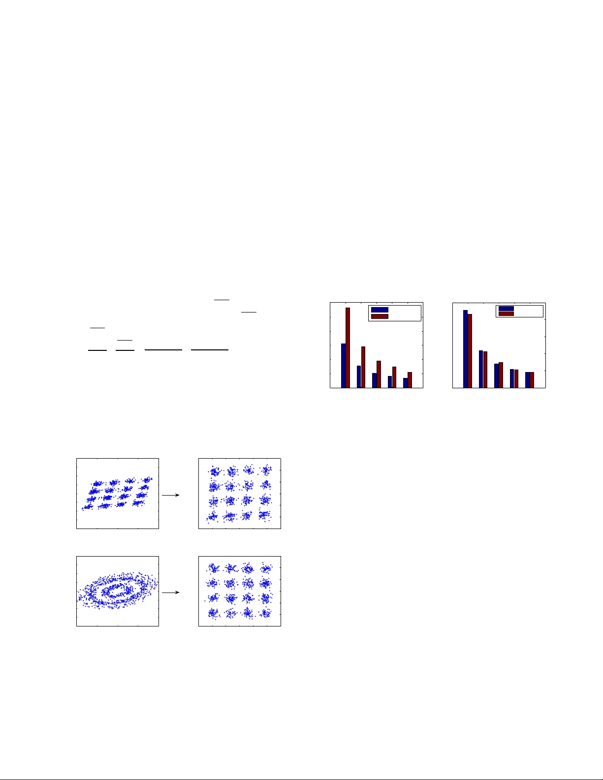
Blind Estimation Algorithms for I/Q Imbalance in Direct Do wn-con v ersion Recei vers Peiyang Song ∗ † , Nan Zhang ∗ , Hang Zhang † and Fengkui Gong ∗ ∗ State Ke y Laboratory of ISN, Xidian University , Xi’an 710071, China † Science and T echnology on Communication Networks Laboratory , Shijiazhuang, China Email: pysong@stu.xidian.edu.cn, nzhang@xidian.edu.cn, 80090385@qq.com, fkgong@xidian.edu.cn Abstract —As known, r eceivers with in-phase and quadrature- phase (I/Q) down con version, especially direct-con version archi- tectures, always suffer from I/Q imbalance. I/Q imbalance is caused by amplitude and phase mismatch between I/Q paths. The performance degradation resulting from I/Q imbalance can not be mitigated with simply higher signal to noise ratio (SNR). Thus, I/Q imbalance compensation in digital domain is critical. There are two main contributions in this paper . Firstly , we proposed a blind estimation algorithm for I/Q imbalance parameters based on joint first and second order statistics (FSS) which has a lower complexity than con ventional Gaussian maximum likelihood estimation (GMLE). This can be used for further precessing such as equalization in presence of r eceiver IQ imbalance. In addition, we find out the reason of error floor in con ventional I/Q imbalance compensation method based on conjugate signal model (CSM). The proposed joint first order statistics and conjugate signal model (FSCSM) compensation algorithm can reach the ideal bit error rate (BER) performance. Index T erms —I/Q imbalance, blind estimation algorithm, first and second order statistics, conjugate signal model I . I N T RO D U C T I O N W ith increasingly demanding requirements for low-cost and lo w-po wer wireless recei vers, I/Q imbalance problem has attracted more attention in both industrial and academic communities. I/Q imbalance is caused by amplitude and phase mismatch between in-phase and quadrature-phase branches in analog front-end, which is unav oidable in practical imple- mentation. It always leads to serious performance degradation in receivers, especially those with low-cost radio frequency front-end (e.g. direct conv ersion architecture). This distortion, unfortunately , can not be mitigated by simply improving SNR. Hence, dealing with I/Q imbalance in digital domain becomes critical, especially for communications with large modulation order . Most literatures so far focus on data-aided estimation al- gorithms, such as least mean squares (LMS) [1], decision- directed (DD) [2], the e xpectation maximization (EM) [3], maximum likelihood (ML) [4], minimum mean squared error (MMSE) [5], etc. More recently , [6] describes an iterati ve I/Q compensation algorithm using both the training symbols and data symbols. Estimation by known symbols usually achieves a rapid conv ergence. Ho wever , the pilot symbols can also result in low spectral efficiency . This problem has become particularly sev ere as the spectrum resources are increasingly valuable. A fe w ef fecti ve blind algorithms can also be found for I/Q imbalance estimation. [7], for the first time, introduces the blind source separation (BSS) into I/Q imbalance estimation. The advanced BSS technology , like joint approximative diago- nalization of eigenmatrix (J ADE) algorithm [8], is an efficient approach to correct I/Q imbalance, whereas it always suffers from significantly higher complexity and sev ere performance degradation when interfered by frequency offset. [9] treats the I/Q imbalance problem as a conjugate signal model (CSM), where the observed signal is a linear combination of the desired signal and its complex conjugate. Howe ver , the algorithm always suffers from error floor which is especially sev ere in high order modulation. In addition, [10] and [11] deriv e estimated v alues of amplitude and phase mismatch by approximating quadrature amplitude modulation (QAM) symbols as tw o-dimensional Gaussian variables. The estimated parameters are used for equalization in presence of receiv er I/Q imbalance. Especially , [12] Addresses the compensation of transmitter I/Q imbalances and carrier frequency of fset (CFO) for uplink single-carrier interlea ved frequency-division multiple-access (SC-IFDMA) systems, which is of greater interest for the 5G networks. Throughout the letter, we define the notation as follows. W e use bold-face upper case letters like X to denote matrices, bold-face lower case letters like x to denote column vectors, and light-face italic letters like x to denote scalers. x i is the i th element of vector x . x i is the i th column vector of matrix X . The complex conjugate of a complex x is represented as x ∗ . I is the identity matrix. <{·} and ={·} denote the real and imaginary part of complex numbers, respectively . E [ · ] represents the expectation. [ · ] T and [ · ] H denote the transpose and conjugate transpose operations, respecti vely . ˆ x (or ˆ X ) is the estimated value of x (or X ). I I . I / Q I M B A L A N C E S Y S T E M M O D E L Mathematical model of I/Q imbalance has been established and widely used [1]–[14]. In this section, we consider the transmission of baseband signals over a flat-frequency noisy channel and I/Q imbalance in direct conv ersion receivers. Bandpass signal is giv en by x RF ( t ) = I ( t ) cos (2 π f c t ) − Q ( t ) sin (2 π f c t ) , (1) where f c is the carrier frequency , I ( t ) is the in-phase compo- nent of baseband signal and Q ( t ) is the quadrature-phase one. The receiv ed signal can be written as r ( t ) = x RF ( t ) + ω RF ( t ) = r c ( t ) cos (2 π f c t ) − r s ( t ) sin (2 π f c t ) , (2) where ω RF ( t ) is real-valued additive white Gaussian noise (A WGN). r c ( t ) and r s ( t ) are equiv alent baseband signals which contain transmitted signals and the noise. In direct con version architecture, do wn con version is realized by multi- plying receiv ed signal r RF ( t ) by local carrier and then passing the result through a low-pass filter . As described before, the in- phase local oscillator (LO) signal z LO,c ( t ) and the quadrature- phase one z LO,s ( t ) alw ays exhibit both amplitude and phase mismatch, i.e. z LO,c ( t ) = 2(1 + α ) cos (2 π f c t + θ ) , (3a) z LO,s ( t ) = − 2(1 − α ) sin (2 π f c t − θ ) , (3b) where α and θ are amplitude and phase imbalance parameters, respectiv ely . It is worth noting that amplitude mismatches in different branches do not need to be exactly equal. The symbol α is used to make the formula more symmetrical. Thus, the final output baseband signal influenced by I/Q imbalance in receiv er can be written as y c ( t ) = LP F { z LO,c ( t ) r ( t ) } = (1 + α ) cos ( θ ) r c ( t ) | {z } sig nal + (1 + α ) sin ( θ ) r s ( t ) | {z } interf er ence , (4a) y s ( t ) = LP F { z LO,s ( t ) r ( t ) } = (1 − α ) sin ( θ ) r c ( t ) | {z } interf er ence + (1 − α ) cos ( θ ) r s ( t ) | {z } sig nal , (4b) where LP F {·} accounts for lo w-pass filter . y c ( t ) and y s ( t ) are baseband signals of I/Q paths. As can be seen from (4a) and (4b), when ideal LO is taken into consideration (i.e. α = 0 and θ = 0 ), receivers can successfully recover the original baseband signals as y c ( t ) = r c ( t ) and y s ( t ) = r s ( t ) . But in practice, when amplitude and phase imbalance occur, each of these two branches will be interfered by the other . (4a) and (4b) can be expressed by y ( t ) = [ y c ( t ) y s ( t )] T as y ( t ) = (1 + α ) cos ( θ ) (1 + α ) sin ( θ ) (1 − α ) sin ( θ ) (1 − α ) cos ( θ ) | {z } Γ r c ( t ) r s ( t ) . (5) Fig. 1 is the block diagram of this system model. LO LPF LPF x RF ( t ) r ( t ) z LO , c ( t ) z LO , s ( t ) y c ( t ) y s ( t ) A WG N w RF ( t ) Fig. 1. I/Q imbalance system model with real signals The model can be derived by the complex env elope [15] of real signal as well. Receiv ed signal r ( t ) can be gi ven as r ( t ) = < e r ( t ) e j 2 πf c t = 1 2 e r ( t ) e j 2 πf c t + e r ∗ ( t ) e − j 2 πf c t , (6) where e r ( t ) = r c ( t ) + j r s ( t ) is the complex en velope of receiv ed signals r ( t ) . Here, local carrier generated by LO can be written as e z LO ( t ) = 2 K 1 e − j 2 πf c t + K 2 e j 2 πf c t , (7) where K 1 = [(1 − α ) e j θ + (1 + α ) e − j θ ] / 2 , (8a) K 2 = [(1 + α ) e j θ − (1 − α ) e − j θ ] / 2 . (8b) Equiv alent complex signal after do wn con version can be giv en as e y ( t ) = LP F { r ( t ) e z LO ( t ) } = K 1 e r ( t ) | {z } sig nal + K 2 e r ∗ ( t ) | {z } interf er ence , (9) which is shown in Fig. 2. ( • ) * r ( t ) ~ y ( t ) A W G N w R F ( t ) ~ K 1 K 2 x R F ( t ) ~ ~ L P F Fig. 2. I/Q imbalance system model with equiv alent complex en ve- lope, where ( · ) ∗ denotes conjugate value. As can be seen from (9), when ideal LO is implemented, K 1 = 1 and K 2 = 0 . Baseband signal can be accurately recov ered without interference. If α and θ can not be ignored, the entire complex baseband signal will be interfered by the conjugate v alue of itself. Obviously , (9) is equiv alent to (4a) and (4b), i.e. y c ( t ) = <{ e y ( t ) } and y s ( t ) = ={ e y ( t ) } . (10) Then, we consider the QAM modulation and assume the in-phase and quadrature-phase components of the transmitted signal as I ( t ) = X ` a ` ψ ( t − `T ) , (11a) Q ( t ) = X ` b ` ψ ( t − `T ) , (11b) where, a ` and b ` belong to the QAM alphabet. ψ ( t ) is a square-root raised-cosine pulse, and T is the symbol period. The discrete-time in-phase and quadrature-phase components after down-con version and matched filtering can be written as y c,k = y c ( k T ) = (1 + α )[( a k + n c,k ) cos ( θ ) + ( b k + n s,k ) sin ( θ )] , (12a) y s,k = y s ( k T ) = (1 − α )[( a k + n c,k ) sin ( θ ) + ( b k + n s,k ) cos ( θ )] , (12b) where n c,k and n s,k , which uncorrelate with each other , are the samples of zero-mean real-valued Gaussian random variables with variance σ 2 n / 2 . I I I . P RO P O S E D J O I N T FI R S T A N D S E C O N D O R D E R S T A T I S T I C S ( F S S ) A L G O R I T H M Firstly , α and θ are set as the trial values of I/Q imbalance parameters. [10] proposed an estimation algorithm for α and θ by Gaussian maximum likelihood. The estimated parameters are used for equalization in presence of I/Q imbalance. Here, we propose a simpler algorithm for estimation of α and θ . It is easy to break (12a) and (12b) into Y = y c y s = 1 + α 0 0 1 − α | {z } Ψ cos ( θ ) sin ( θ ) sin ( θ ) cos ( θ ) r c r s | {z } Ω , (13) where r c,k = a k + n c,k and r s,k = b k + n s,k are samples of r c ( t ) and r s ( t ) which contain both QAM symbols and noise. (13) can be written as Y = Γ R , where R = [ r c , r s ] T . When α and θ ha ve been estimated, original signal can be recovered by R = Γ − 1 Y . W e use C R , C Ω and C Y represent cov ariance matrix of R , Ω and Y respectively . W ith E [ Ω k ] = [0 , 0] T , C Ω can be giv en as (14) (see the bottom of this page). Then, we assume that the receiv ed signals before down con version are circular symmetry , i.e. E [( r c,k + j r s,k ) 2 ] = 0 , which can be further written as E [ r 2 c,k ] = E [ r 2 s,k ] and E [ r c,k r s,k ] = 0 . W e set P r = 2 E [ r 2 c,k ] = 2 E [ r s,k ] 2 as the average po wer of receiv ed symbols. C R and C Ω can be written as C R = 1 2 P r I , (15a) C Ω = 1 2 P r 1 sin (2 θ ) sin (2 θ ) 1 , (15b) which re veals that phase mismatch θ will not change the av erage power (i.e. the variance) of receiv ed symbols of each branch. Similar to C Ω , C Y can be written as C Y = E [ ΨΩΩ T Ψ T ] = E [ Ψ C Ω Ψ T ] = 1 2 P r (1 + α ) 2 (1 − α 2 ) sin (2 θ ) (1 − α 2 ) sin (2 θ ) (1 − α ) 2 . (16) T o av oid power measurement, we gi ve a calculation of P r by baseband signal y s and y c . Resulting from the i.i.d . property of a k and b k (also n c,k and n s,k ), it is obvious that η = E [ | ( a k + n c,k ) cos ( θ ) + ( b k + n s,k ) sin ( θ ) | ] = E [ | ( a k + n c,k ) sin ( θ ) + ( b k + n s,k ) cos ( θ ) | ] . (17) Thus, relationship between α and receiv ed symbols can be deriv ed by (12a) and (12b) as E [ | y c,k | ] = (1 + α ) η and E [ | y s,k | ] = (1 − α ) η . (18) Then, we replace the statistical av erage by actual receiv ed symbols. And (18) can be written as 1 + α 1 − α = P N k =1 | y c,k | P N k =1 | y s,k | , (19) where α can be easily calculated by recei ved symbols. Also, we giv e the expression of θ from (16) as 1 2 (1 − α 2 ) P r sin (2 θ ) = E [ y c,k y s,k ] = E [ y s,k y c,k ] . (20) Then, we replace the statistical av erage by actual receiv ed symbols. And (20) can be written as 1 2 (1 − α 2 ) P r sin (2 θ ) = 1 N X N k =1 ( y c,k y s,k ) , (21) where P r can be obtained from (16) by recei ved symbols and calculated α as P r = 1 N " P N k =1 y 2 c,k (1 + α ) 2 + P N k =1 y 2 s,k (1 − α ) 2 # . (22) At last, α and θ can be written as α = P N k =1 | y c,k | − P N k =1 | y s,k | P N k =1 | y c,k | + P N k =1 | y s,k | , (23a) θ = 1 2 arcsin 2(1 − α 2 ) ρ cs (1 − α ) 2 ρ c + (1 + α ) 2 ρ s , (23b) where ρ cs = P N k =1 ( y c,k y s,k ) , ρ c = P N k =1 y 2 c,k and ρ s = P N k =1 y 2 s,k . As known, frequency offset does not change the circular symmetry property of receiv ed signal. Hence, the proposed algorithm can achieve a strong robustness to frequency offset. I V . P R O P O S E D J O I N T FI R S T O R D E R S TA T I S T I C S A N D C O N J U G A T E S I G NA L M O D E L ( F S C S M ) A L G O R I T H M Firstly , we give a brief introduction of con ventional CSM algorithm. The blind I/Q imbalance estimation is addressed in [9] with conjugate signal model, i.e. e Y = e y e y ∗ = K 1 K 2 K ∗ 2 K ∗ 1 e r e r ∗ = K e R . (24) Assuming that the target signal e r is circular or proper , the target here is to find a matrix W to whiten or decorrelate the components of e r as e z = W e Y = W K e R = T e R , (25) where T is the equiv alent system matrix. When perfect estima- tion is taken into consideration, T ≈ I . W can be calculated as W = U Λ − 1 / 2 U H , (26) C Ω = E ΩΩ T = cos 2 ( θ ) E [ r 2 c,k ] + sin 2 ( θ ) E [ r 2 s,k ] sin ( θ ) cos ( θ )( E [ r 2 c,k ] + E [ r 2 s,k ]) sin ( θ ) cos ( θ )( E [ r 2 c,k ] + E [ r 2 s,k ]) sin 2 ( θ ) E [ r 2 c,k ] + cos 2 ( θ ) E [ r 2 s,k ] (14) where U and Λ are calculated by eigenv alue decomposition of C e Y , i.e. C e Y = E ( e Y e Y H ) = U Λ U H . (27) Compared to earlier BSS technology , CSM algorithm has a much lower complexity . Howe ver , its performance seems not to be reliable enough. In practical, we find that CSM algorithm always suffers from a certain error floor , which is especially se vere in high order modulations. A large number of simulations rev ealed that the error floor usually mitigates as the amplitude mismatch α reduces. When α is not taken into consideration, BER performance of CSM algorithm can be improv ed to ideal bound. (13) has proved that the influence of α and θ on impaired signals is independent. Thus, one possible solution to eliminate the error floor is compensating amplitude mismatch in ad- vance. Our proposed FSCSM algorithm add a pre-processing module before con ventional CSM method. The pre-processing can be giv en as Y 0 = y 0 c y 0 s = ˆ Ψ − 1 Y = ˆ Ψ − 1 ΨΩ = 1 1+ ˆ α 0 0 1 1 − ˆ α y c y s = 1+ α 1+ ˆ α 0 0 1 − α 1 − ˆ α | {z } Ψ 0 cos ( θ ) sin ( θ ) sin ( θ ) cos ( θ ) r c r s | {z } Ω , (28) where ˆ α is the estimated value of amplitude mismatch cal- culated by (23a). Ψ 0 = ˆ Ψ − 1 Ψ is the remaining amplitude mismatch matrix. When accurate estimation of α is performed, Ψ 0 ≈ I and Y 0 ≈ Ω . Then, the equiv alent complex baseband signal for CSM is Y 0 = [ e y 0 , e y 0 ∗ ] T , where e y 0 = y 0 c + j y 0 s . −2 −1 0 1 2 −2 −1.5 −1 −0.5 0 0.5 1 1.5 2 (a) In−phase Quadrature−phase −1.5 −1 −0.5 0 0.5 1 1.5 −1.5 −1 −0.5 0 0.5 1 1.5 In−phase Quadrature−phase −2 −1 0 1 2 −2 −1.5 −1 −0.5 0 0.5 1 1.5 2 (b) In−phase Quadrature−phase −1.5 −1 −0.5 0 0.5 1 1.5 −1.5 −1 −0.5 0 0.5 1 1.5 In−phase Quadrature−phase Fig. 3. Constellation comparison pre- and post- FSCSM algorithm. (a) signal is impaired by I/Q imbalance. (b) signal is impaired by both I/Q imbalance and frequency offset. The ef fect of proposed FSCSM algorithm can be shown in Fig. 3. Signals impaired by I/Q imbalance can be perfectly compensated. Frequency of fset will be completely reserved and wait for further processing. Here we consume that the frequency offset is kno wn and has been fully correct after our FSCSM module. Further performance analysis will be giv en in Section V. V . N U M E R I C A L R E S U LTS In this section, we assess the performance and robustness of our proposed algorithms. T able I shows the operations required for GMLE and proposed FSS. As can be seen, compared to GMLE, our proposed FSS estimation is free of complicated square root operations. Also, less additions and multiplications are required. Additional bit shift and absolute value operations introduced by proposed FSS are relativ ely easy for implementation. Fig. 4 reports the mean square error of estimated α and θ achie ved by GMLE and FSS versus the number of receiv ed 16-QAM symbols N , for SNR=18dB. Estimation results of both algorithms are quite close which means the accuracy degradation of proposed FSS caused by simplification is slight enough. 100 200 300 400 500 0 0.2 0.4 0.6 0.8 1 1.2 x 10 −3 N MSE of α 100 200 300 400 500 0 0.5 1 1.5 2 2.5 x 10 −3 N MSE of θ GMLE [11] proposed FSS GMLE [11] proposed FSS Fig. 4. Mean square error (MSE) of estimated α and θ achieved by GMLE and proposed FSS Fig. 5 reports the con vergence of different algorithms in 16-QAM modulation with SNR=18dB. I/Q imbalance is set as α = 0 . 2 and θ = 10 ◦ . ∆ f is the normalized CFO. T o ignore the effect of frequency offset compensation algorithms on the BER performance, we assume that ∆ f is kno wn at receiv er and is perfectly compensated after I/Q imbalance compensation. Simulation shows that our proposed FSCSM algorithm performs a fast BER performance con vergence. The BER can be eventually upgraded to A WGN bound (i.e. BER of ideal receiv er without I/Q imbalance). Moreov er , when frequency offset is taken into consideration, BER performance of both the proposed algorithms does not degrade. Fig. 6 compares the performance of con ventional CSM with proposed FSCSM blind algorithm in 16-QAM, 64-QAM and 256-QAM, respecti vely . Parameters are set as α = 0 . 3 , θ = 10 ◦ and ∆ f = 0 . And N is large enough to guarantee that the BER performance has con verged. As can be seen, for con ventional CSM algorithm, the degradation of performance can not be mitigated by simply increase N . Our proposed FSCSM algorithm solves this problem without knowledge of an y other additional information and improv e the BER performance to A WGN bound. T ABLE I O P E R A T I O N N U M B E R R E Q U I R E D F O R G M L E A N D P R OP O S E D F S S A L G OR I T H M S Algorithm Square Root Multiplication Addition Absolute V alue of Real Number Bit Shift Di vision Arcsin GMLE [11] 3 3 N + 2 3 N − 1 0 0 3 1 proposed FSS 0 6 2 N + 4 2 N 2 3 1 500 1000 1500 10 −4 10 −3 10 −2 10 −1 10 0 N (a) BER 0 500 1000 1500 10 −4 10 −3 10 −2 10 −1 10 0 N (b) BER JADE [7] [8] CSM [9] proposed FSCSM AWGN bound JADE [7] [8] CSM [9] proposed FSCSM AWGN bound Fig. 5. Con ver gence of different blind algorithms in 16-QAM, for SNR=18dB. (a) ∆ f = 0 ; (b) ∆ f = 0 . 01 15 20 25 30 35 10 −4 10 −3 10 −2 10 −1 SNR (dB) BER AWGN bound CSM proposed FSCSM 64−QAM 256−QAM 16−QAM Fig. 6. Performance of conv entional CSM and proposed FSCSM algorithm in different QAMs V I . C O N C L U S I O N This letter has addressed the I/Q imbalance problem in single-carrier direct conv ersion receiv ers. T wo blind estima- tion and compensation algorithms hav e been put forward. The proposed FSS algorithm achiev es less complexity than con ventional GMLE estimation with slight enough perfor- mance degradation. In addition, the reason of error floor in con ventional CSM algorithm is found out. Our proposed FSCSM algorithm can eliminate the error floor of CSM and achiev e ideal BER performance. It is worth noting that the proposed two algorithms both perform a strong rob ustness to frequency of fset, which makes it work well before frequency offset estimation algorithms. Furthermore, both the proposed algorithms are not sensitiv e to modulation order . Our results show that they also perform well with 4096-QAM and 256- APSK. A C K N O W L E D G E M E N T This work is supported in part by joint fund of ministry of education of China (6141A02022338) and the opening project of science and technology on communication networks laboratory (KX162600027). R E F E R E N C E S [1] A. T arighat, R. Bagheri, and A. H. Sayed, “Compensation schemes and performance analysis of IQ imbalances in OFDM recei vers, ” IEEE T rans. Signal Process. , vol. 53, no. 8, pp. 3257–3268, 2005. [2] S. Tra verso, M. Ariaudo, I. Fijalkow , J.-l. Gautier, and C. Lereau, “Decision-directed channel estimation and high I/Q imbalance compen- sation in OFDM receivers, ” IEEE T rans. Commun. , vol. 57, no. 5, 2009. [3] M. Marey , M. Samir, and O. A. Dobre, “EM-based joint channel estima- tion and IQ imbalances for OFDM systems, ” IEEE T rans. Br oadcast. , vol. 58, no. 1, pp. 106–113, 2012. [4] M. Marey , M. Samir, and M. H. Ahmed, “Joint estimation of transmitter and receiv er IQ imbalance with ML detection for Alamouti OFDM systems, ” IEEE T rans. V eh. T echnol. , vol. 62, no. 6, pp. 2847–2853, 2013. [5] X. Cheng, Z. Luo, and S. Li, “Joint estimation for I/Q imbalance and multipath channel in millimeter-wav e SC-FDE systems, ” IEEE Tr ans. V eh. T echnol. , vol. 65, no. 9, pp. 6901–6912, 2016. [6] X. Zhang, H. Li, W . Liu, and J. Qiao, “Iterativ e IQ imbalance compensa- tion receiver for single carrier transmission, ” IEEE T rans. V eh. T echnol. , vol. 66, no. 9, pp. 8238–8248, 2017. [7] M. V alkama, M. Renfors, and V . Koi vunen, “ Advanced methods for I/Q imbalance compensation in communication receiv ers, ” IEEE T rans. Signal Pr ocess. , vol. 49, no. 10, pp. 2335–2344, 2001. [8] J.-F . Cardoso, “High-order contrasts for independent component analy- sis, ” Neural computation , vol. 11, no. 1, pp. 157–192, 1999. [9] M. V alkama, M. Renfors, and V . Koi vunen, “Blind signal estimation in conjugate signal models with application to I/Q imbalance compensa- tion, ” IEEE Signal Process. Lett. , vol. 12, no. 11, pp. 733–736, 2005. [10] D. Maltera and F . Sterle, “ML estimation of receiver IQ imbalance pa- rameters, ” in Proc. IEEE International W aveform Diversity and Design Confer ence , 2007, pp. 160–164. [11] D. Mattera, L. Paura, and F . Sterle, “MMSE WL equalizer in presence of receiv er IQ imbalance, ” IEEE T ransactions on Signal Pr ocessing , vol. 56, no. 4, pp. 1735–1740, 2008. [12] D. Darsena, G. Gelli, and F . V erde, “Joint blind channel shortening and compensation of transmitter I/Q imbalances and CFOs for uplink SC- IFDMA systems, ” Physical Communication , vol. 11, pp. 25–35, 2014. [13] F . Gu, S. W ang, J. W ei, and W . W ang, “Higher-order circularity based I/Q imbalance compensation in direct-con version receivers, ” in Pr oc. IEEE V ehicular T echnology Conference , 2016, pp. 1–6. [14] L. J. W ong, W . C. Headley , and A. J. Michaels, “Estimation of transmit- ter I/Q imbalance using con volutional neural networks, ” in Computing and Communication W orkshop and Confer ence (CCWC), 2018 IEEE 8th Annual . IEEE, 2018, pp. 948–955. [15] A. Goldsmith, W ir eless Communications . Cambridge University Press, 2005.
Original Paper
Loading high-quality paper...
Comments & Academic Discussion
Loading comments...
Leave a Comment