RF-Based Direction Finding of UAVs Using DNN
This paper presents a sparse denoising autoencoder (SDAE)-based deep neural network (DNN) for the direction finding (DF) of small unmanned aerial vehicles (UAVs). It is motivated by the practical challenges associated with classical DF algorithms suc…
Authors: Samith Abeywickrama, Lahiru Jayasinghe, Hua Fu
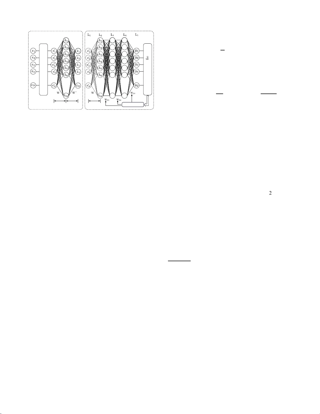
RF-based Directi on Finding of U A Vs Using DNN Samith Abeywickrama ∗† , Lahiru Jayas inghe † , Hua Fu † , Subash ini Nissanka † , and Chau Y uen † † Singapore Uni versity of T e c hnology and Design, S ingapore ∗ National Univ ersity of Singap o re, Singapore Email: samith@u.nus. edu , { aruna jayasinghe,hu a fu,yu enchau } @sutd.ed u.sg Abstract —This paper presents a sparse denoising autoencoder (SD AE)-based deep neural network (DNN) f or the directio n finding (DF) of small unmanned aerial vehicles (U A Vs). It is motiv ated by the practical challenges associated with classical DF algorithms such as MUSIC a nd ESPRIT . The proposed DF scheme is practical an d lo w-complex in th e sense that a p hase synchronization mechanism, an antenn a calib ration mechani sm, and the analytical model of the ant en na radiation pattern ar e not essential. Al so, the proposed DF method can be implemented using a single-channel RF r eceiver . The paper v alidates the proposed method experimentall y as well. Index T erms —Drone surv eill ance, direction finding, U A V tracking I . I N T RO D U C T I O N The use of civilian d rones h as increased drama tica lly in recent ye a r s. Likewise, drones are fast gain ing popula r ity around the world [1 – 5]. Howe ver , drone use in a pro b lematic manner h as stirred public concer ns. For exam p le, in January 2015 a drone crashed at the White House [ 6], raising co ncerns about security risks to the g overnm ent building; in March 2 016 a Lufthansa jet came within 200 feet of co lliding with a dron e near L os Angeles In ternational Airpor t [ 7]; and dro nes have been accused of being used to violate the priv a cy and even carry crimina l activities [8]. Th ese ev ents giv e am ple self- evident examples tha t developing a surveillance system for suspect d rones is of param ount importance. The a uthors of [ 9] sou ght to detect a d r one using Radio Frequency (RF) as it can w ork day and night and at all weather con d itions. Mo st of the commercial dro n es comm u- nicate frequently with their controller s, and the downlink, i.e. , video sign al and telemetry signals (flight speed, position, altitude, and b attery le vel), between the d rone and its co ntroller is always p r esent. T o this end, this paper presents a dro n e surveillance system, b y eavesdropping on the commu nication between a drone and its gr ound contr oller . The system can estimate dron e’ s dire c tion (or bearing) by processing the data transmitted fr om the drone to its controller using a sing le channel wireless receiver . Theref ore, no dedicated transmitter is requ ired at the surveillance system. RF based d irection finding (DF) tech n iques have been well studied, and the classical high-r e solution techn iq ues such as The support of NSFC 61750110 529 and SUTD-MIT Internation al Design Center is gratefully ackno wledged. The first two autho rs contrib uted equally . MUSIC [10] and ESPRIT [11] are con sidered to b e the most po pular algo rithms. Howe ver , MUSIC and ESPRIT are inherently mu lti-channel techniqu es b ecause those algorith ms require a snap shot o bservation. This means, th e base-band data from all ante n na eleme n ts should be extracted simulta- neously so that a data corr elation matrix can be f ormulated . Therefo re, multiple channels shou ld be cohere n t. Howe ver , in most receivers, th e dig ital down co n verter (DDC) cha in uses a coordin ate rotation d igital compu ter (CORDIC), wh ich has a random start-up p osition on power up. The CORDIC therefore creates a random p hase each time when the chan nels o f the receiver are initialized, but r emains co nstant throu ghout the operation [1 2]. The r efore, calibrating th is start-up phase values of ea c h RF cha nnel becom es necessary to realize a coher ent multi-chan nel receiv er . Clearly , this increases the ha r dware complexity and the power consumption . Most of the civilian dron es u se W iFi-like OFDM fo r their commun ication. They ar e usually unknown, wideband, and transmitted in b u rst-mode. Such signal characteristics pose challenges with classical DF techniques. Howe ver , if on ly the signal power measuremen ts are utilized, performin g DF is practically feasible e ven with such signals [13 – 16]. In [16], signal power measur e ments that are obtained from a switched beam ante n na array are utilized to e stima te the d irection of a W iFi transmitter . As the actu al radiation pattern of the antenna is v ital f or th ese metho ds, still it bou nds with some practical challenges. Ther efore, we prop o se a p r actical and a low- complex drone DF method in this pa p er , and our co ntributions can be summar iz e d as fallows. T o the best of authors’ kn owledge there has not b een any other method th at inv olves d eep neura l network in the context of dr o ne DF . W e focu s on a system wh ich com- prises a direc tional antenn a arr ay h a ving N antennas, and a single channel receiver . By proce ssing the signals that are transmitted from the dron e to its grou nd con tr oller , the single ch a n nel receiver measu r es the r eceiv ed signal power at th e each an tenna using a RF switching mech anism. Then , the obtained power v alu es are fed to the propo sed spar se denoising auto encoder (SD AE)-based deep neur a l n etwork (DNN). More pr e cisely , the fir st hidden laye r of the network extracts a r o bust spa rse r epresentation o f the received power values. Th en, th e rest of the network utilizes th is sparse representatio n to classify the dire c tion of the drone signal. It should be noted that a phase synchronizatio n mech anism, . . . . . . . . . . . . . . . . . . . . . . . . . . . . . . Data Preprocessing Softmax Classi er Single Channel SDR Single-pole-N-throw Antenna Switc h N-element Directional Antenna Arra y Encoder SDAE-DNN Fig. 1. The System Model. an antenna gain calibratio n mech a nism, and the analytical model o f the antenn a radiation p attern a re no t essential for this single ch annel implem entation. The paper validates the propo sed m ethod experimentally through a software defined radio (SDR) imp lementation in con junction with T ensorFlow [17]. Furthe rmore, suc h an exper imental validation for drone DF is not com mon in the literature, and can be highlighted as another con tribution of this paper . The paper o rganization is as follows. The system mod el is presented in Section II. Sectio n III d iscusses the proposed deep architecture . Th en, in Section IV, we validate the propo sed method using experimental results. Section V concludes the paper . T o prom ote repro ducible research , the cod es for gen erating most of th e results in th e pape r are made av ailable on the website: http s://github.com/LahiruJayasinghe/DeepDOA. I I . S Y S T E M M O D E L W e con sider a system which consists of a single channel receiver , and a cir cular antenna array eq uipped with N dir e c - tion antennas, see Fig . 1. T he an tenna array is con nected to the receiver u sing a non- reflectiv e Single- Pole-N-Throw (SPNT) RF switch. The switching period is T s . Suppo se that a far- field dron e signal imp in ges on th e antenna array with azimuth angle θ ∈ [0 2 π ) . T h e receiv ed signal at the n − th antenna element can be g i ven as r n ( k ) = a n ( θ ) s ( k ) + n n ( k ) , (1) where k is the sample ind ex, a n ( θ ) is the n − th antenn a response vector for the azimuth an gle θ , s ( k ) is the dro ne transmitted signa l as it arrives at the antenn a array , n n ( k ) is circularly symmetr ic, indepen dent and iden tically distributed, complex additive white Gaussian no ise (A WGN) with zero mean and variance σ 2 , and n ∈ { 1 , · · · , N } . Here, a n ( θ ) follows the for m o f a n ( θ ) = G n ( θ ) e j 2 π λ β n ( θ ) , (2) where G n ( θ ) is the real numbered an tenna gain for the azimuth angle θ , λ is the signa l wav elength, and β n ( θ ) = d co s " 2 π ( n − 1 ) N − θ # , (3) where d is the radius o f the circular a ntenna array [18]. Since we consider a p ractical DF meth od in this pape r , s ( k ) and a n ( θ ) ar e assum e d to be unkn own. Therefo re, our objective is to recover the azim u th angle θ , while the parameters s ( k ) and a n ( θ ) ar e unkn own. W e fo cus on a power measur ements b ased appro ach. T o this end, the ensem ble averaged received signal power at the n − th antenna elemen t can be given as P n = E h | r n ( k ) | 2 i = E h a n ( θ ) s ( k ) + n n ( k ) a n ( θ ) s ( k ) + n n ( k ) ∗ i = | a n ( θ ) | 2 E h | s ( k ) | 2 i + E h | n n ( k ) | 2 i = G 2 n ( θ ) P s + σ 2 , (4) where G 2 n ( θ ) = | a n ( θ ) | 2 , P s = E h | s ( k ) | 2 i , σ 2 = E h | n n ( k ) | 2 i , and E[ · ] den o tes the expectation operator . Here, (4) follows from the fact that s ( k ) and n n ( k ) are indep endent an d uncorr elated, i.e. , E[ s ( k ) n ∗ n ( n )] = E[ s ∗ ( k ) n n ( n )] = 0 . It can be ob served that the received p ower values at the a n tenna elements n i and n j , where i, j ∈ { 1 , · · · , N } and i 6 = j , are not id entical, since G 2 i ( θ ) 6 = G 2 j ( θ ) . W e h a ve this prop erty thanks to the gain variation of the d irectional antenna a rray in [0 2 π ) . Th erefore, it is d e sira ble to ha ve an un d erlying relationship (or a p attern) between { P n } N n =1 and θ . The proposed method is as fo llows . The receiver sequ en- tially acti vates one an tenna elemen t at a time u sin g the SPNT RF switch, an d mea su res the cor respondin g recei ved power value. Dur in g the a c tivation of n − th anten na, P n is measured, whe r e n ∈ { 1 , · · · , N } . A single switching cycle is equiv alent to N activ ations, starting fro m the first anten n a to the N − th antenn a. Let p = [ P 1 , · · · , P N ] ⊤ denote the power measuremen ts corresp onding to a sing le switching cycle. As it is d epicted in Fig. 1, x = [ x 1 , · · · , x N ] ⊤ is obtained during the prep rocessing stage, wher e x n = P n P N i =1 P i . (5) This means, x n is the ratio between P n and th e sum mation of all p ower values within the same switching cycle. In the next section, we d iscuss how the pro p osed network recovers θ fro m x . Data Corruption Encoder Decoder . . . . . . . . . . . . . . . . . . . . . . . . . . . . . . . . . . Softmax Classi er . . . . . . . . . . Cross-Entrop y (a) SDAE T raining Phase (b) DNN T raining Phase Encoder Fig. 2. Trainin g Phases. I I I . S DA E - D N N A R C H I T E C T U R E The propo sed deep ar chitecture co mprises a trained SDAE and a traine d DNN, followed by a fully-co nnected softmax classifier layer, see Fig. 1. Durin g the training ph ase of the SD AE (Fig. 2-(a) ), the prepro cessed received power values { x n } N n =1 are assigned to th e input u nits. Therefo re, the n umber of neu r ons in the input lay er is eq u al to the number of elemen ts N in the dir ectional anten na array . Then, th e values of the hidden layer units a re calculated a s h = f ( W f c ( x ) + b e ) , (6) and ou tput layer values are calculated as ˆ x = f ( W ⊤ h + b d ) , (7) where f ( · ) is non-linear activ ation fu nction that ope rates element-wise on its argument, W ∈ R M × N denotes the encoder weight matrix, b e = [ b e 1 , . . . , b e M ] ⊤ and b d = [ b d 1 , . . . , b d N ] ⊤ denote th e bias vectors, and f c ( · ) is a stochas- tic corru p ter which add s no ise accor ding to some noise model to its in put, i.e. , x ′ = f c ( x ) , wher e x ′ = h x ′ 1 , . . . , x ′ N i ⊤ . In (6), f c is n o n-determ inistic, since it cor rupts the same set of received power values { x n } N n =1 in different ways ev ery time { x n } N n =1 is p assed thr o ugh it. W ⊤ is th e deco der weight matrix, wh ich ensures that the outpu t layer reco nstructs the input as p recisely as possible ( W ⊤ is the m a trix tra n spose o f W ). Here, w e particularly target on reconstructing the in put received power values at the o utput layer o f the SD AE. T o this end, the parameters of SDAE ( W , b e , an d b d ) are o ptimized such that the reco nstruction error is minim ized, while it sub jecting to a spar sity con stra in t. Th is sparsity constraint encoura g es the sparse acti vation of the hidd en layer units. Ther efore, the cost func tion ca n be given as L ( W , b e , b d ) = T X i =1 ( ˆ x i − x i ) 2 + β M X m =1 KL( ρ || ρ m ) , (8) where T is the size of the trainin g data set, β is a hyp er parameter 1 , ρ is the sparsity p arameter, ρ m = 1 T T X i =1 h m ( x i ) is the average activ atio n level of the m - th hidden unit wher e h m ( x i ) denotes the activation of the m − th un it for the input x i , an d KL( ρ || ρ m ) = ρ log ρ ρ m + (1 − ρ ) log 1 − ρ 1 − ρ m (9) is the Kullback-Leibler (KL) d ivergence [19]. Fro m (9), it can be observed that KL( ρ || ρ m ) = 0 , if ρ m = ρ , and otherwise it increases mono tonically as ρ m div erges from ρ . T yp ically , ρ is a very small value close to zer o. Th erefore, when the cost function (8) is minimiz e d, the parame ter ρ e n forces { ρ m } M m =1 to be close to zero, while the dominant neuron s th at rep r esent specific features stay non - zero. Now , the decoder is discard ed, and th e tra ined encod er is connected to the DN N as a fully connected layer . Next, the DNN trainin g phase is commen ced. As Fig. 2- (b) de p icts, DNN co mprises three fully conne c ted h id den layers, i.e. , L 2 , L 3 , and L 4 , and a softmax layer [20] for the task of classification. Since L 2 is an elem ent of the trained encoder, it uses the same activation function f . Hidden lay ers L 3 and L 4 use Rectified liner Unit (ReLU) [21 – 23] as their activ ation fun ction. Again, noise corrup ted r eceiv ed power values n x ′ n o N n =1 are the train ing inputs. Now , data need to be labelled into Q classes due to the use of softmax classifier, where the la b el is the d irection of the d rone signal com ing from. Therefo re, the learning strategy is sup ervised in this training phase. Since, W is the pre-tr ained enco der weigh t matrix, it will not b e o p timized ag ain. Th erefore, only the weight matrices W D1 , W D2 , and W D3 are o ptimized d uring this trainin g phase. Remark 1: It should be n oted that the incomin g d rone signal with direction θ occup ies a cer ta in isolated po int in the angle domain of [0 2 π ) . Therefor e, θ is sparse in the spatial domain, and this spar sity can be exploited to estimate θ . Here, we use this sparse p roperty , and it can be summa r ized as f ollows. In the cost fun c tion (8), the squared err or is calcu lated b etween the non- corrupted power values and th e r econstructed power values, while the noise-co rrupted power v alues are fed to the network. This c o st fun ction is sub ject to a sp arsity co n straint as well. Th erefore, ev en when the system o p erates in a n o isy en vironm e n t, the first hid den layer (or W ) of the network extracts a r o bust sparse representatio n of the in put power values. Th en, th e rest of the network utilizes th is sparse representatio n to classify (or estimate) θ . In th e n ext section, we will validate our propo sed method using experim ental re sults. 1 β operates as the trade-of f paramete r betwee n the squared error and KL( ρ || ρ m ) , and its value can be empiricall y decided during the training process. T ABLE I C O N F U S I O N M A T R I X W H E N T H E P R O P O S E D N E T W O R K I S U S E D . 0 0 45 0 90 0 135 0 180 0 225 0 270 0 315 0 0 0 95 1 1 0 3 0 0 0 45 0 1 97 0 0 1 1 0 0 90 0 1 1 98 0 0 0 0 0 135 0 0 0 0 100 0 0 0 0 180 0 3 3 0 0 92 2 0 0 225 0 0 0 4 0 1 95 0 0 270 0 0 0 3 0 0 1 95 1 315 0 0 0 0 0 0 0 1 99 I V . E X P E R I M E N TA L V A L I DAT I O N Our experimen tal setup com prises a SDR (USRP B210), and a f our element sector antenna, which is a variant of the antenna implemented in [2 4]. W e use o nly a sin g le RF receiving channel of the SDR. Ther efore, the SDR is connected to the antenn a using a non-reflective Single-Pole-4- Throw (SP4T) RF switch. DJI Phantom 3 is considered as the target dro ne throu g hout the experimen t. The d rone downlink channels occupy the b andwidth from 2.4 0 1 GH z to 2.481 GHz, each has 10 MHz bandwidth OFDM signal. This OFDM signal transmitted by th e dr one provides the main sou rce to per form the DF task. Fig. 3-(a) rep resents the environment that we used for the training data co llection. This is a large g round with an open ar e a . Also, ther e was negligible RF in terference on the 2.401 GHz - 2.4 8 1 GHz rang e. T o simplify the experiment, we vir tu ally divided the area into eight octan ts, see Fig. 3- (b). Each octan t is considered as one direction d uring th e experiment. F or example, the first octant is consid e red as 0 degrees directio n, while the second octant is considered as 45 degrees direction , and so on. Th erefore, when the drone is flying, its direction is indicate d b y its correspo n ding o ctant. In th e train e d network, L 5 − th layer has eigh t neu rons (we have eight classes fo r the directio n classification, or, Q = 8 ) and L 1 − th layer ha s fou r neuro ns (the antenna ar ray has four elements, or, N = 4 ). The hidd en lay ers L 2 , L 3 , and L 4 have 200 , 12 , and 12 neu rons, resp e cti vely . These values hav e been empirically decid ed durin g the trainin g process. After the training phase, the ev alu ation is d one in a d ifferent en vironm e n t. Now , the frequen cy spectru m (2 .401 GHz - 2.481 GHz) suffers from W iFi and bluetooth interferen ces. T o this en d, two exper iments have been car ried out. First, we ev alua ted the pr oposed deep arch itecture, and its conf usion matrix is given in th e T able I. Next, we co n sidered a baseline method, where only a con ventional DNN is implemented without the L 2 layer (oth er lay ers h a ve same numb er of nodes). Its confusion matr ix is given in th e T a b le II. Note that the confusion m atries represent th e per centage (%) values. It c an be observed that the prop osed deep architecture is certainly T ABLE II C O N F U S I O N M A T R I X W H E N O N LY T H E D N N I S U S E D . 0 0 45 0 90 0 135 0 180 0 225 0 270 0 315 0 0 0 94 5 1 0 0 0 0 0 45 0 10 88 1 0 0 1 0 0 90 0 4 1 88 1 3 0 0 3 135 0 0 6 1 93 0 0 0 0 180 0 30 4 3 0 60 2 0 1 225 0 1 0 4 0 2 91 0 2 270 0 0 0 1 0 2 1 94 2 315 0 0 0 0 0 3 0 0 97 (a) Training Field (b) Directio n Configuration Fig. 3. The T raining Field and The Direction Configurati on. robust, and it outperf orms the baseline metho d. Since our imple m entation doe s n ot u se multiple RF chan nels and any inf o rmation abou t the antenna radiation pattern, it is not desirable to compare our results with conv entional technique s. T h erefore, we om it such simulatio n/experimental results. Further intere sting experimen tal ev aluations a n d in- sights will be pre sen ted in fu tu re extensions of this work. V . C O N C L U S I O N This pap er has propo sed a novel DF method to b e used in a d rone surveillance system. The system comprises a single channel receiver and a directional antenna array . The receiver sequen tially activ ates each an tenna in the arr ay , and measures the received p ower values. The power m easurements correspo n ding to each switchin g cycle are fed to the pro- posed dee p network . Then, it per forms DF b y exploitin g the sparsity prop erty of the incoming dr one sign al, and the gain variation property of the d ir ectional antenna array . The paper has validated the p roposed m ethod experimen ta lly . Also, it has be en pr oven th at a ph a se synchr onization mechanism, an antenna gain calibration m e c hanism, and the an alytical mod e l of the an tenna radiation pattern are not essential for this single channel implementatio n. In future the scheme will be applied to portable, SDR-based prototyp e design [9] and field test and experiment. R E F E R E N C E S [1] Y . Sun, H. Fu, S. Abeywic krama, L. Jayasinghe, C. Y uen, and J. Chen, “Drone classification and localiz ation using micro-dopple r signature with lo w-frequenc y signal, ” T o appear in IEEE International Confer ence on Communication Systems , 2018. [2] Q. W u, Y . Zeng, and R. Zhang, “Joint trajecto ry and communication design for multi-U A V enabled wirel ess networks, ” IEEE T rans. W ir eless Commun. , vol. 17, no. 3, pp. 2109–2121, 2018. [3] Q. W u and R. Zhang, “Common throughput maximiza tion in UA V- enable d OFDMA systems with delay conside ration, ” T o appear in IE EE T rans. Commun. , 2018. [4] Q. Wu, J. Xu, and R. Zhang, “Capacity charact eriza tion of UA V-enabled two-use r broad cast channel, ” T o appear in IEEE J. Sel. Areas Commun. , 2018. [5] Q. W u, L. Liu, and R. Zhang, “Fundament al trad eof fs in communicati on and trajector y design for UA V-enabled wirele ss netw ork, ” Submitt ed to IEEE T rans. W irele ss Commun. , 2018. [6] B. J ansen, “Drone crash at white house rev eals security risks. ” [online] https:/ /www .usatoday .com/story/ne ws/2015/01/26/ , 2015. [Accessed on 26 November 2017]. [7] J. Serna, “Luft hansa jet and drone nea rly collide near lax. ” [onl ine] www .latimes.com/loca l/la no w/la- me- ln- drone- n ear- miss- lax- 20160318 , 2016. [Accessed on 26 Nov ember 2017]. [8] A. Morrow , “Couple accuses neighbor of stalk ing with drone. ” [online ] https:/ /www .suasnews.com/ 2014/12/ , 2014. [Accessed on 26 Nove mber 2017]. [9] H. Fu, S. Abeywic krama, L. Zhang, and C. Y uen, “Low comple xity portabl e passiv e drone surveill ance via SDR-based signal processing , ” IEEE Commun. Mag . , vol. 56, pp. 112–118, Apr . 2018. [10] R. Schmidt, “Multiple emitter location and signal parameter estimat ion, ” IEEE T rans. A ntennas and Pr opagation , v ol. 34, pp. 276–280, Mar . 1986. [11] R. Ray and T . Kailath, “ESPRIT-estimation of signal parameters via rotati onal in vari ance tech niques, ” IEEE T rans. A coustic s, Speech, Signal Pr ocessing , vol. 37, pp. 984–995, Jul. 1989. [12] J. va n der Merwe, J. Malan, F . Maasdorp , and W . D. Plessis, “Multi- channe l softwa re defined radio experimen tal e v aluat ion and analysis, ” in Pr oc. Instituto T ecnolog ico de A er onautica (IT A ) , Sep. 2014. [13] H. Fu, S. Abeywickrama , and C. Y uen, “ A robust phase-ambiguity- immune doa estimati on s cheme for ante nna array , ” T o appear in IEEE Internati onal Confer ence on Communicat ion Systems , 2018. [14] S. Maddio, M. Passafiume , A. Cidronali, and G. Manes, “ A closed-form formula for RSSI-based doa estimation with switched beam ante nnas, ” in Proc. 2015 Europe an Radar Confer ence , Sep. 2015. [15] R. P ¨ ohlmann, S. Zhang, T . Jost, and A. Dammann, “Powe r-Ba sed Directi on-of-Arri val Estimation Using a Single Multi -Mode Antenna, ” ArXiv e-prints , Jun. 2017. [16] S. Maddio, M. Passafiume, A. Cidronali, and G. Manes, “ A scalable dis- trib uted position ing system augmenting wifi tec hnology , ” in Pr oc. IEEE Internati onal Confer ence on Indoor P ositioning and Indoor Navigat ion , Oct. 2013. [17] M. Abadi and A. Agarw al, “T ensorflow: Large-sca le machin e learning on heterogeneou s distrib uted systems, ” ArXiv e-prints , Mar . 2016. [18] B. R. Jackson, S. Rajan, B. Liao, and S. W ang, “Directi on of arri val estimati on using directi ve antennas in uniform circular arrays, ” IEE E T rans. Antennas and P r opagation , vo l. 63, pp. 736–747, Feb . 2015. [19] S. Kull back and R. Leibler , “On information and sufficien cy , ” The Annals of Mathemati cal Statistics , vol. 22, pp. 79–86, Mar . 1951. [20] C. Bishop, P attern R eco gnitio n and Machine Learning . Springer-V erla g, 2006. [21] K. Hara, D. Saito, and H. Shouno, “ Analysis of function of rectified linea r unit used in deep learning, ” in P r oc. IEEE Internation al J oint Confer ence on Neural Netwo rks , Jul. 2015. [22] L. Jayasinghe, N. W ijerathne, and C. Y uen, “ A deep learning approach for classificat ion of cleanline ss in restrooms, ” T o appear in Pr oc. IEE E Internati onal Conf er ence on Intellig ent and Advanced Systems , Aug. 2018. [23] L. Jaya singhe, T . Samarasin ghe, C. Y uen, and S. S. Ge, “T emporal con volutio nal memory netwo rks for remaining useful life estimat ion of industria l machine ry , ” T o appear in IEEE International Conf er ence on Industrial T ech nolog y , 2019. [24] L. Y ang, Z . Shen, W . Wu, and J. D. Z hang, “ A four -elemen t array of wideband lo w-profile H-Plane horns, ” IE EE Tr ans. V ehicul ar T echnol- ogy , vol. 64, pp. 4356–4359, Sep. 2015.
Original Paper
Loading high-quality paper...
Comments & Academic Discussion
Loading comments...
Leave a Comment