Universal Computer aided design for electrical machines
Electrical machines are devices that change either mechanical or electrical energy to the other and also can alternate the voltage levels of an alternating current. The need for electrical machines cannot be overemphasized since they are used in vari…
Authors: Aravind Vaithilingam Chockalingam, Ikujuni Grace Olasehinde, Rozita Teymourzadeh
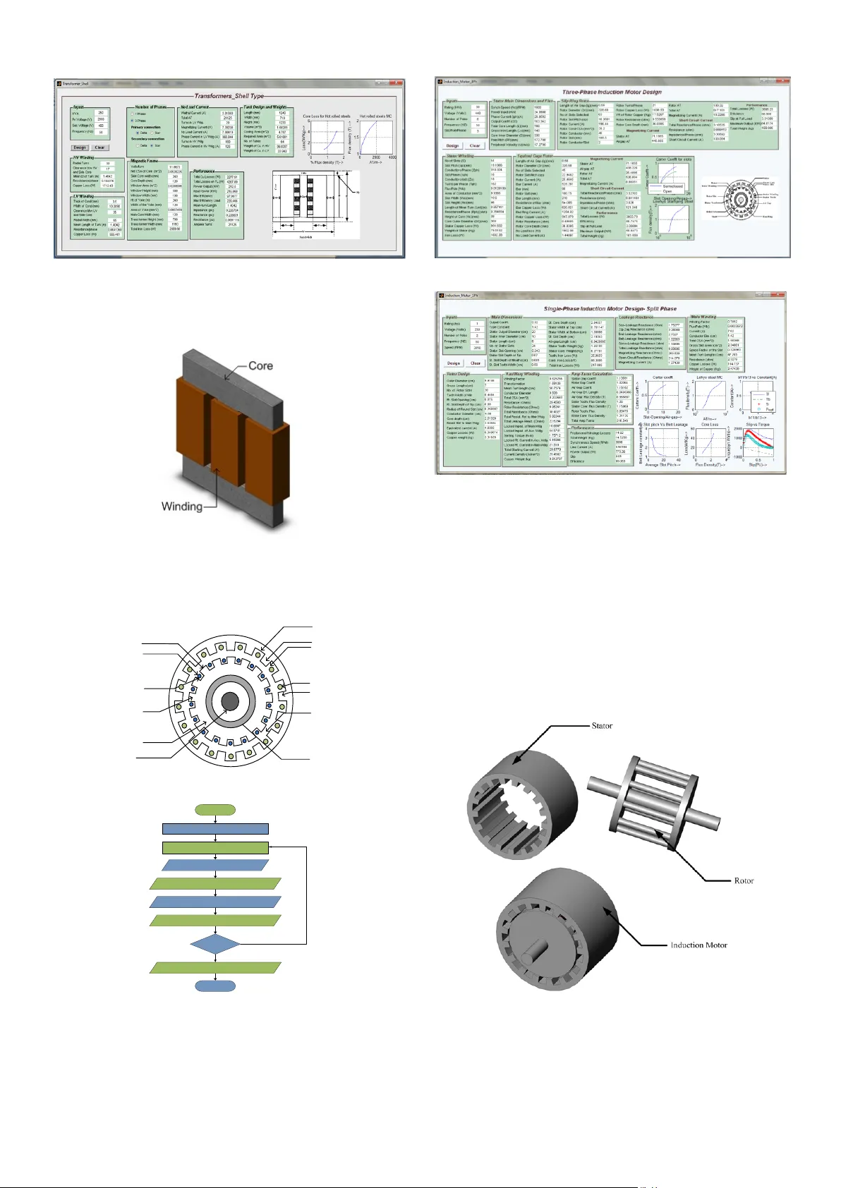
Universal Computer Aided Design for Electrical Machines 1 Aravind Vaithilingam C hockalingam, 2 Ikujuni Grace Olase hinde , 3 Rozita Teymo urzadeh Department of Electrical and Electronic Engineering Faculty of Engineering, UCSI University Kuala Lumpur, Malaysia Abstract — Electrical machines are devices that change eit her mechanical or electrical energy to the other and als o can alternate the voltage levels of an alternating current. The need for electrical machines cannot be overemphasized since they a re used in various a pplications in the w orld today. Its design is to meet the specifications as stated by the user and this design has to be an econo mical one. The design therefore revolves around designing the machine to meet the stipulated perform ance required, the cost available and the lasti ng life of the m achine. This w ork aims to eli m inate the tediousness involved in the manual hand calculations of d esigning the machines by m aking use of a graphical user interface and using iterations in situations where the data would have been a ssumed. I. I NTRODUCTI ON The d esign of motor i n gener al is a complex pro cedure and hence req uires a n eas y and understandable design method and tool f or th e designer. C AD de sign for this w ork looks into the design of DC machine, i nduction machines, sync hronous machines, transfor mers, Rotary SR M and the i nductance profile of SRM[1]. The induction motor is divided i nto the design of three pha se and sin gle phase induction m otor with each ha ving its own GUI. S ynchronous m otor is divided into salient and round ro tor type and the trans former is d ivided into the shell and cor e t ype. T he designs have bee n made with consideration to t he performance of the machine. Ot her limitations s uch as cost a nd insulating material have not being taken into consideration. The design o f electrical machines [2], [3] has looked considerab le in to the d esign of v arious machines. The reluctance machine desig n works on the inductance profile and d esign of the rotar y SRM [1] , [4] , [5 ]. II . D ESIGN T OO L The analysis and synthesis way of designing electrical machines have b een used in t he design of t he machines. T he synthesis method is used for DC machine, AC machine, a nd transformers. The analysis method h as been used for the design of switched reluctance method [1] . T here is a general toolbox interface th at introd uces the user to the de sign of each electrical machine. T his is as sho wn in the fig.1 This introd uctory GUI makes use of radio buttons t hat lin k s the designer to the various machine design GUI p ages. Fig. 1: Introductory GUI The m aterials used for the design o f electrical machines greatly depend on the hysteres is loop of the machines. Various materials have been used for the design of this toolbox and it is as shown in the fi g . 2 . 10 100 1000 10000 100000 1000000 0.0 0.5 1.0 1.5 2.0 2.5 3.0 3.5 Flux density (T) AT/m M22 M19 Lohys 42 quality cast -steel Fig . 2 : Magnet ization curves The machine speci fications for each machine design G UI include the follo wing: The ratings of the machine such as the voltage, KVA, peak current, speed, nu mber of poles. For some of t he motor design, t he req uired outer surface para meters o f t he machine are required suc h as the total diameter and len gth of the machine. For SRM, stator and rotor pole arc , length of air gap required and active or passive element o f the linear SRM. Number of phases for the machine. III . MACHINE DESIGN Start Input machine specifications as per the machine to be designed Define input values to be assumed as per machine designed Main dimensions of machine Objective function achieved? Stop Change parameters Winding design parameters Performance Analysis CAD design Yes No Fig. 2: Generalized machine design f lowchart Fig .3 is a generalised design procedure for electrical machines. The analysis on ho w to design reluctance machine is ha s b een extensive ly do ne by [1], [4] , [5]. The design o f t he other electrical machines ha s being done by [2], [3]. The design proce dure looks into the design o f the main dimensions, field windings, No lo ad ca lculations, perfor mance characteristics and others. For all machines the main criteria for th e design is getting t he output co efficient. T he output coefficient is gotten as (1) Where P is the o utput o f the machine in KVA, D is the diameter of armature (m) a nd L is the gross le ngth o f armat ure (m), and N is the speed of the machine in RPM. Other relevant co nsiderations are that o f the magnetic and electric loadings and are specified as follo ws. , Wb Where B av = specific magnetic loading (Wb/m 2 ), D is diameter of the ar mature (m) a nd L is the len gth of t he armature ( m) and P is the number of poles. The specific magnetic load ing , (2) Total electr ic loading; , A Where I z .Z is the total electric loading, a c is the specific electric loading in A/m. The specific electric load ing, (3) IV . R ESULTS T RANSFO RMERS Transformers are divided into shell and core t ype transformers. Although shell t ype tran sformers ar e hard ly used, they are still i n used in small cap acity machines. B oth types of transfor mers have b eing designed . T he GUI enables the user to be able to select the co re type, number of p hases and the winding required. 2 a a a Ww Ww W H Hw Yoke Core Hy 10 core shell Yoke Core Ww D W Hw H Hy a 10 core transformer Fig. 3: Transformers CS Start Main dimensions of magnetic frame Input specifications Core and winding design No load current parameters Tank design with cooling tubes Performance calculations Performance ? Assumed variables End Yes CAD Fig. 4: Transformer flowchart Fig. 5: Core type GUI result Fig. 6 : shell ty pe GUI result For the G UI desi gn, provisio ns are made so that t he desig ner can pick if the type of core required, number of phases and windings to be used. Fig. 7 : Transfo rmer CAD I NDUCTIO N MOTORS The design GUI f or th e induction motor has been divided i nto single phase and three pha se GUI. Stator Stator Core Stator Slot Stator Winding Stator Tooth Air Gap End Ring Rotor Rotor Winding Rotor Slot Rotor Tooth Rotor Core Shaft Fig. 8 : Induction motor CS Start Main dimensions Input Specifications Rotor and winding design Amp-Turns evaluations Performance evaluations Performance ? Assumed variables such as choice of loadings End Yes CAD No Fig. 9 : IM design flo wchart Fig. 10 : Three phase IM GUI result Fig. 11 : Single phase IM GUI result The slip of induction motor matters a lot as it greatl y a ffects the torq ue o f the motor. The slip is the difference bet ween t he synchronous speed and the actual speed. T he need for slip is because an ind uction motor does not generate voltage when the rotor is running at a synchronous speed to that of the magnetic field. T his is the reason why a much d ifference in the slip, yields a large torque val ue. T he grap h as seen fro m the GUI shows that with increase in the slip of the machine, the torque is greatly increased until it gets to a value where the slow spee d in moveme nt o f t he ro tor is not s trong enough to cut across the magnetic field thereby resulti ng in a r eductio n in the torque produced. Fig. 12 : Squirrel cage IM CAD S YNCHRONOU S MACHI NES Stator Stator Tooth Stator Slot Air Gap Yoke Field Pole Shaft Rotor N N S S Fig. 13 : Synchronous motor CS Start Stator design Input specifications Rotor design Performance evaluations Performance ? Assumed variables such as choice of loadings End Yes CAD No Fig. 14 : Synchronous design flowcha rt Fig. 15 : Salient pole GUI res ult Fig. 16 : Round rotor GUI result The synchronous m achine GUI shows the plots of the field winding d epth, core losses vs. flux density, carter’s coefficient for the slots and open circuit c haracteristics of t he machine. The op en circuit characteristics tes t is taken wh en the generator is operating without load, running at synchrono us speed and the field current is increa sed fro m zer o to maximum. As seen fro m the graph in t he GUIs’, the cur ve is almost per fectly li near until so me saturation i s seen at high field currents. This is because the reluctance of the motor at an unsaturated iron fra me is far less than that o f the air gap thereby all mmf see m to pass through the air gap. As the iron gets saturated, the relucta nce increases rat her slowl y. Fig. 17 : Salient pole CAD DC MACHINE Magnetic flux Yoke Field Pole Pole shoe Commutator Armature Shaft Interpole Air gap Field winding Fig. 18 : DC machine CS Start Selection of number of poles Input specifications Armature design Performance ? Assumed variables such as choice of loadings End Yes CAD No Change assumed variables Field system design Commutator and brushes Performance evaluations Fig. 19 : DC machine flowcha rt Fig. 20 : DC machine GUI re sult Fig. 21 : DC machine CAD SWITCHED RELUCTANCE MOT OR Fig. 22 : SRM CS Start Machine Specifications – ( Po, Nr, Ip,V ) Design Outputs -( Do, hs, hr, Dsh, Tavg, etc) Input Parameters – ( D, L, lg , etc.) Tavg >= Treq Cost Analysis End No Yes Fig. 23 : SRM design flo wchart Fig. 24 : Rotary SRM design GUI result The SRM d esign G UI as sho wn abo ve sho ws the torque, height o f rotor and stator, back iron thickness, pole width, turns per phase, aligned and unaligned inductance and t he average air gap power. If t he average tor que generated d oes not g ive the req uired output, the user is r equired to c hange some inputs para meters such as the stator and rotor pole arc. This will help move the aver age torq ue closer to the required torque. When this is achieved, the motor can then be said to have been designed. Fig. 25 : SRM inductance pro file result The inductance profile is a grap h of the relatio nship between the inductance and the ro tor position. T he inductance profile shows four distinct regions. For the example S RM, t he motor is at a fully al igned position whe n its angle is 30° while 0° is when the m otor is at a fully unaligned position. The inductance profile results shown ar e that of the unaligned inductance, ali gned inductanc e, tor que, graphical analysis of some o f the perfor mance of the motor and the intermediate position inductance. The results as shown in t he GUI below, shows the i nductance for each flux path, the mag netic flu x density ass umed for that flux pat h a nd the reluctance f or the fl ux p ath. FP in the figure indicates flux pat h while the number in front indicates the number of flux p ath. B indicates magnetic flux densit y assumed for that path and R indicates the reluctance o f t he motor at that path. Fig. 26 : SRM CAD V. C ONCL USION A generalised tool box for optimisation of computer ai ded design for electrical machines ha s been b uilt successf ully. T he SRM design has bee n verifie d by using a nalytical a nd cyc lic integration method. [5 ], [ 2]. Others have been verified by using manual calc ulations. Altho ugh these m achines have being desig ned, this may not b e the optimum desig n because it does not put into consideration the cost o f the machine, available materials to b e used, huma n labour available, temperature rise and o ther constraints. VI . A CKNOWL EDGMENT The authors wish to record CERVI E, UCSI University fo r supporting this research work. R EFERENCES [1] Krishnan, R., “Switched Reluctance Mo tor Drives: Modeling, Simulation, An alysis, Design, a nd Applications”, CRC Press, 2 001 [2] Aravind C.V, Ka mala K. C. (2 003). Design of electrical apparatus. Chennai: Charulatha publications [3] K.M. Vishnu Murthy (20 08). Computer Aided Design of Electrical Mach ines. Hyderabad : BS Publications [4 ] Praveen V., Design of Switched Reluctance Motors and Develop ment of a U niversal Controller for Switched Reluctance and Permanent Magnet Brushless DC Motor Drives, 200 1, pp. 1- 104. [5] Aravind CV, Samuel Bright., Design of reluctance motors for lo w sp eed applications, Bachelor’ s d egree Thesis, May2011
Original Paper
Loading high-quality paper...
Comments & Academic Discussion
Loading comments...
Leave a Comment