Sparse Multiband Signal Acquisition Receiver with Co-prime Sampling
Cognitive radio (CR) requires spectrum sensing over a broad frequency band. One of the crucial tasks in CR is to sample wideband signal at high sampling rate. In this paper, we propose an acquisition receiver with co-prime sampling technique for wide…
Authors: Yijiu Zhao, Shuangman Xiao
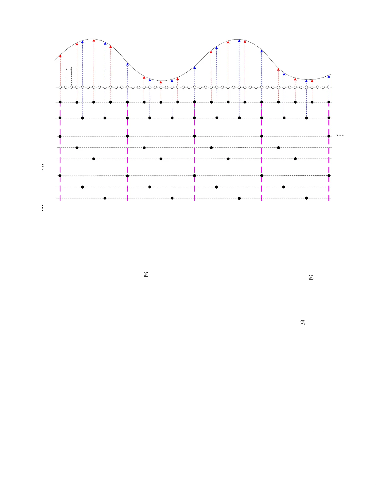
1 Abstract — Cognitive ra dio (CR) r equires sp ectrum sensing o ver a broad frequency band. One of the crucial tasks i n CR is to sample wideband signal at high samp ling rate. In t his paper, w e propose an acquisition rece iver with co-prime sampling technique for w ideband sparse signals, which occupy a s mall part of band range. In this proposed acquisition receiver, we use two low spee d analog- to -digital converters (A DCs) to c apture a common sparse multiband signal, w hose band loca tions are unknown. The two ADCs are synchronously clocked at co-pri me s ampling rates. The obtained samples are re-s equenced into a g roup of uniform sequences with lo w rate. We deriv e the mathematical m odel for the receiver in the freq uency domain a nd present its signal reconstruction algor ithm. Compared to the existing sub-Nyquist sampling te chniques, such as multi-coset samp ling and modulated wideband co nverter, the proposed approach has a simple syst em architecture and can b e im plemented w ith o nly two sam plers. Experimental results are repo rted to de monstra te the feasibility and advantage of the proposed model. For sparse multiband signal with unknow n spectral support, the proposed system requires a sampling rate much lower than Nyquist rate, while produces satisfactory reconstruction . Index Terms — Co -prime sampling , cognitive radio, multi-coset sampling, compressed sensing , spectrum sensin g. I. I NTRODUCTI ON N wireless co mmunication, wide spectral band is divided into narrowband slices. B efore being trans mitted in those spectral slices, baseband signal is m odulated by high carrier frequency. The increasing demand fro m new wireless communication users has be come a cruc ial is sue recen tly. However, studies [1], [2] have shown that this over -crowded spectrum is usuall y underutilized. A lthough co gnitive radio (CR) would allo w secondar y users to use the licensed spectral slices when t he cor responding pr imary user s are not ac tive [3], CR typically monitors the spectru m b ased on the Nyquist sampling theorem and requires high sam pling rate. The Ny q uist rates o f signals ar e high a nd may e xceed the specifications of best co mm ercial analog - to -di gital converters ( ADCs). ADC has become a bo ttleneck of high spee d acquisition system. In CR, signals can be described as the union o f a small Manuscript re ceived xx. xx, 2018. This w ork is supporte d by t he Na tional Natural Science F oundation o f China (Grant No. 6167111 4 ). Y. Zhao , and S. Xiao a re w i th the School of Automation Engi neering, University of Electronic Science and Technology of China, Chengdu 611731 , China (e-mail: y i jiuzhao@uestc.edu. cn; shuangma nxiao@hotmail.co m ). number of narro wband tran smissions over a wide band range. Consequently, signal spectrum is o ften sparse and ca n be modeled as sparse multiband signal. For such sparse multiband signal, it ma y be reconstructed from sub -Nyquist samples i n a more intelligent way. Multi-coset sa mpling (MCS) is a non-unifor m p eriodic sub-Nyquist sampling method [4], [5] for sparse multiband signal. MCS consists of a bank of ADCs clocked at th e sam e rate but w it h di fferent ph ase delays to facilitate concurrent sampling of the w ideband signal . The performance of MCS hinges upon the accurate clock p hase delays, which is co mplex and costly. On the other hand, the number o f ADCs is proportional to the n umber of t ransmissions. Compared to MCS , multi-rate sa mpling (MRS) [6 ] needs less channels. Most of MR S's c hannels could operate at sub-Nyqu ist rate, while the sampled spectr um should be unaliased i n at least o ne of the channels. Co -prime sampling [7 ], [8] was pro posed to esti mate directions- of -arrival (DOA) in the spatial do main. I n t he DOA estimation, co -pri me array can increase the d egree o f freed om and improve the est imation ac curacy . In [9], a sa mpling model with t hree cha nnels w as proposed to estimate the frequencies o f multiple sinusoids. The three c hannels w ork at sub -Nyquist rate, whose undersampling ratios are pairwise co -prime. I t is an efficient approac h for harmonic sparse signal sampling. Spar se fast Fourier transform (sFFT) [ 10 ] , [ 11 ] algorithm provides a low bound for number o f sam ples. Specifically, to achieve the bound, the coefficients of sig nal need to be p seudo-randomly permuted. sFFT requires custo m ADCs that can rando mly sub-sample the signal with inter-sample spacing as small as the inverse of the signal ba ndwidth. Compressed sensing (CS) is an emerging alter native approac h for the acquisition of sparse signals [ 12 ], [ 13 ]. For spectral sparse signal, t he i dea of CS is t hat t he spect ral information is muc h smaller than its ba ndwidth, and si gnal can be reconstructed from its low dimensional samples. Employing random de modulation tech nique, Kirolos et al . [ 14 ], [ 15 ] developed an analog- to -information co nverter ( AIC) to realize sub-Nyquist r ate sampli ng o f wideband s ignal u sing CS reconstruction. For wideband harmonic sparse signal, AIC has been shown a n effective sampling method. While AIC does not work for sparse multiband signal that i s widel y used in CR . Eldar et al . [ 16 ], [ 17 ] developed a modulated wideband converter (MWC). In particular, MWC could be treated as multiple AIC samplers concurrently, and its channels is pr oportional to the number o f sparsel y al located narr ow band s in the signal spectru m . MW C works for not only harmonic Sparse Multiband Signal Acquisition Receiver with Co-prime Sampling Yijiu Zhao, Memb er, IEEE , and Shuangman Xiao I 2 sparse signal but also sp arse multiband signal. To accomplish sub-Nyquist sam pling , both AIC and MWC need to modulate the wideband signal wi th the pseudorandom pulse seque nces at the N yquist rate. O ther CS based sa mpling technique s ar e also proposed to improve the sa mpling rate [ 18 ], [ 19 ]. Random equivalent sa mpling (RES) [ 20 ], [ 21 ] is a non-uniform sa mpling technique which is widely used in instrumentation applications. RES has a sim ple architecture and only requires a single ADC clo cked at sub -Nyquist rate. In order to produce a s uccessful reconstruction, multiple RES acquisitions need to be run. Moreover, there sh ould be a unique reference point in each RES acq uisition, and a time - to -digital converter circuitr y should be used to measure the trigger time interval. Compared w it h u niform sampling techniques, RES takes considerably longer sampling time. Previously [ 22 ], [ 23 ], CS theory is incorporated into RES technique to enhance the RES signal rec onstruction. It has been tested that much fewer samples are required in RES signal reco nstruction. Co mbine random triggering and random demodulation tec hniques [ 24 ], the bandwidth of ADC is avo ided. However, RES (or r andom triggering) based non -unifor m sampling technique s require multiple acquisitions, which are not app licable for CR. Non-unifor m sampling clock phase also in troduces error in reconstructed wavefor m. In this work, we propo se a sub-Nyquist acquisition receiver based on co -prime sampling technique. D ifferent from conventional co-prime sampling approaches [7 -9] (they f ocus on DOA a nd harmonic spectral estimation ), we consider t he sparse mu ltiband signal. In the proposed approach, signals do not need to be pre-pro cessed as random modulated based methods (such as AIC a nd MWC). In the previous work [ 25 ], two co-prime samplers are a synchronously clocked, a time- to -digital converter circ uitry is required to measure the phase dela y, a nd it wo uld deg rade the per formance o f syste m. In this propo sed sampling model, a common sparse multiband signal is unifor mly and s ynchronously sampled b y only two low speed ADCs ( much smaller number of channels than MCS and MRS). These two ADCs are clocked at co -prime sampling rates (hereafter, the proposed model is referred to SCS : synchronous co-pri me sa mpling). After o ne acquisition, samples are re-sequenced into a group of lo w speed of sampling sequences. We derive the mathematic al expression for SCS, which ca n be used to blindly reco nstruct signal. In co mparison to the popular sub-Nyquist sam pling approac hes, such as e.g. MCS, MWC, RE S, the proposed SCS has simple architect ure. The remaining o f this pap er is o rganized as follows. In section II, we first introduce the sparse multiband si gnal m o del. In Section III W e propose synchronous co -prime sampling model and give the comparison to other related works. Numerical simulatio n results are reported and d iscussed in Section VI, followed b y conclusion in Section V. II. P ROBL EM F ORMULATI ON A sparse multiband signal is a b andlimited, square-integrable , continuous time signal which consists o f a relatively small number of narro w f requency bands over a bo ard spectrum range . Fig. 1 dep icts an exa mple of the sp ectrum of a sp arse multiband signal. Consider a continuous-ti me sparse multiband signal x ( t ) , which is real-valued and s quare-integrable, and with t he Fourier transform (FT ) 2 ( ) ( ) d j ft X f x t e t . (1) Denote by f N yq = 1/ T the Nyquist rate of x ( t ), signal is bandlimited to [ 1/ (2 T ), 1/ (2 T ) ]. Let i b e t he i th ac tive sub-band where X ( f ) 0, whose carrier frequency is f i . The spectral occupation ratio m ay be d efined as R = ( )/|[ ]| where ( ) is the Lebesgue measure of , and |[ ]| = f N yq . Since x ( t ) is spectrum sparse, R << 1 should be satisfied. In CR applications, the locations of the si gnal sub-bands are unknown in advance, signal sho uld be blindly reconstructed. III. S UB -N YQUIST C O - PRIME S AMPLING A. System Model Fig. 2 shows a n illustrativ e sche me of SCS. SCS syste m consists of t wo sampling channels ( ADC1 and ADC2), which uniformly digitize a common inp ut signal. T wo ADCs are synchronously cloc ked at sub-Nyqui st rates. Suppose t he sampling interva ls of two ADCs are L 1 T and L 2 T resp ectively. To qualify sub-Nyquist sampling, we require the integer L 1 and L 2 are much bigger than 1. Moreover, L 1 and L 2 are r equired to be relative co -prime integers. Deno te by L t he least co mmon multiple of L 1 and L 2 , and L = L 1 L 2 . The average sampling rate is ( L 1 + L 2 )/( LT ). Fig. 3 illustrates an exa mple of principle o f SCS, where L 1 = 3 and L 2 = 4 are relative co-prime i ntegers. In Fig. 3, “ Nyquist samples ” i s the digital version o f signal with Nyquist rate that is to be reconstructed. Let x 1 [ n ] and x 2 [ n ] denote the samples x ( t ) x 1 [ n ] ADC1 undersamples by L 1 ADC2 undersamples by L 2 L 1 T L 2 T x 2 [ n ] Fig. 2. Scheme of co-prime sampling. f f 1 f 2 f K - f 1 - f 2 - f K 0 f Nyq /2 -f Nyq /2 Fig. 1. Spectrum-sparse multiband signal. 3 captured b y ADC1 and ADC2. Since ADCs are synchronousl y clocked, x 1 [ n ] and x 2 [ n ] could be treated as under -samples from Nyquist grids, and the y can be expressed as 11 22 [ ] ( ), [ ] ( ), x n x nL T n x n x nL T , (2) where T is the base sa mpling perio d. We group L consecutive N yquist grids in a block. Deno te by L d the greatest common divisor of L 1 and L 2 . There are L d identical sample (samples) from ADC1 and ADC2 in each block. Since the sampling rates of SCS are co -prime, L d = 1, and there is o nly one identical sa mple in each block. If L 1 a nd L 2 are not co -prime, L d would b e greater than 1. A s a res ult, S CS generates more valid samples with low average sa mpling rate. In each block, d enote by C 1 and C 2 the time sta mps that describe the indexes o f sa mples ob tained b y ADC1 and ADC2 respectively. The set s C 1 and C 2 are referred to as the sampling patterns where 11 1 1 2 | : 0 ,1 , ..., 1 ii C c c L i i L , (3) and 22 2 2 1 | : 0 ,1 , ..., 1 ii C c c L i i L . (4) Ob viously, SCS can obtains M ( M = L 1 + L 2 1) different non-uniform samples in eac h block, and their indexes are described by sam pling pattern C = C 1 C 2 . We could construct M uniform sampling sequences, which pick one sample from each block, and the index i s given by C . There are L 2 samples in each b lock fro m ADC1, and then L 2 uniform sampling sequence s can be constructed 1 1 ( ), [] oth erw ise 0, i i c n x nLT c T xn , (5) and L 1 sampling sequences co nstructed from samples obtain ed by ADC2 2 2 ( ), [] oth erw ise 0, i i c n x nLT c T xn . (6) For sampling seque nce 1 [] i c xn , its discrete -time Fo urier transform (DTFT ) 1 2 i j fLT c Xe can be directly calculated: 11 2 1 /2 1 / 2 1 [ ] exp 2 exp 2 1 exp 2 ii j fLT cc n i n L i lL X e x n j fnLT x nLT c T j fnLT ll X f j c T f LT LT LT , (7) where L is assumed to be an even num ber and i {0, 1, ..., L 2 T Nyquist samples block #1 block #2 1 0 [] c xn 1 2 [] c xn 2 0 [] c xn 2 1 [] c xn 1 [] xn 2 [] xn block #3 block #4 2 2 [] c xn 1 1 [] c xn Fig. 3. An illustration of co-prime sampling. 4 1}. Because x ( t ) is assumed to be bandlimited to , we have finite summatio n limits in the last equation in (7). Since 1 2 i j fLT c Xe is periodic with period 1/( LT ), w e can choose only one period of 1 2 i j fLT c Xe . Here we restrict f 0 , and 0 1 0, LT . (8) For odd L , in (7), the range of l should be [ ( L 1)/2, ( L 1)/2], and 0 = [ 1/(2 LT ), 1/(2 LT )]. Define 1 2 i j fLT c Ye as: 11 2 1 2 /2 1 / 2 1 exp 2 1 exp 2 ii j fLT j fLT i cc L i lL Y e j fc T X e ll X f j c LT LT L , (9) where f 0 . Denote b y 1 [] i c yn the inverse DTFT o f 1 2 i j fLT c Ye . Clearly, 1 [] i c yn is the shifted version of 1 [] i c xn , which is right shifted b y 1 i cT . Similarly, we define seque nce 2 [] i c yn , and its DTFT can be expressed as: 22 2 2 2 /2 2 / 2 1 exp 2 1 exp 2 ii j fLT j fLT i cc L i lL Y e j fc T X e ll X f j c LT LT L , (10) where f 0 . Since s amples i ndexed by 1 0 c and 2 0 c are identical, we require i {1, . .., L 1 1} in (10). We arrange 1 2 i j fLT c Ye and 2 2 i j fLT c Ye in a vector y ( f ). Denote by y i ( f ) the i th entry of y ( f ), and it can be written as: 1 2 1 2 2 2 2 2 0 i iL j fLT c i j fLT c Y e i L f Y e L i M y . (1 1) Define matrix as: 2 1 2 , 2 12 1 exp 2 0 1 exp 2 l i il l iL K j c i L LT L K j c L i M LT L , (12 ) where l = 0, . .., L 1, and K l = L /2 + 1 + l . Combine (9) and ( 10), we have vector -matrix form as ff yx f 0 , ( 13 ) and the l th entry of x ( f ) has the following expres sion l l K f X f LT x . ( 14 ) Obviously, X ( f ) is partitioned into L spectral s lices with equal width of 1/( LT ) that are the entries o f x ( f ). A ccording to (9) a nd (10), y i ( f ) is also given by 1 2 2 1 2 12 2 22 12 ex p 2 ex p 2 i iL j fLT i c i j fLT iL c j fc T X e i L f j fc T X e L i M y . (15) Although, the ab ove anal ysis is about the real-valued sig nal, the results are also app licable to complex-valued signals. B. Signal Reconstruction Eq n. ( 13 ) ties the FT o f unknown signal a nd sampling sequences in the freq uency do main. To reconstruct sig nal x ( t ), we must first solve pr oblem ( 13 ) . However, M < L , ( 13 ) is an under d etermined problem. Fortunatel y, x ( f ) is sparse, and most of entries of x ( f ) are zeros. T he task o f sup port estima tion is to identify which entries of x ( f ) contain active bands. Supp ort estimation could be realized by exa mining the covarianc e matrix of the SCS seq uences. And the support could be teased out using multiple signal cl assification (MU SIC) algorit hm [26]. Let S denote the index set that m arks the locatio ns of the nonzero entr ies o f x ( f ). x ( f ) is | S |-sparse. In order to solve ( 13 ), we require that | S | < M . Suppor t estim a tion means to f ind S , and problem ( 13 ) can be r ewritten as S S ff yx , (16) where S denotes sub matrix composed of the co lumns of indexed b y S , and vector x S ( f ) contains the non-zero entrie s of x ( f ) indexed by S . Consider the M M covaria nce matrix of y ( f ), 0 0 d d H f H H f H f f f f f f y x R y y xx R , ( 17 ) where R x is the co variance matri x of x ( f ), and H denotes Hermitian transpose. Sin ce x ( f ) is | S |-sparse, only | S | of co lumns and rows of R x will be nonzero, and R y can be reduced as H SS S yx RR . ( 18 ) No te from ( 12 ), has full ra nk. Co nsequently, its s ub-mat rix S also has full rank, and rank( S ) = | S | ( M > | S | is assumed). If rank( [R x ] S ) = | S |, then ( 18 ) im plies rank ( R y ) = | S | (pr oof is given 5 in Appendix A). Consider the ei gen-deco mposition of R y . Let r and n denote the diagonal matrices containing | S | nonzero and M | S | zero eigenvalues respectively, and U r and U n are associated eigenvectors matrices. The eigen-deco mposition may be expressed as , H r r rn H n n H r r r O O y U R U U U UU . ( 19 ) The columns of U r span the sa me space a s that of the columns of R y , a nd range( R y ) = ran ge( U r ). Similarly, ( 18 ) implies range( R y ) = range( S ), and we have range( U r ) = range( S ). Therefore, the colu mns of indexed b y S should lie in t he space spanned b y the columns of U r . Denote by r U P the projection matrix of the space spanned by th e columns of U r . : r H rr U P U U . If the c olumn index i S , then the proj ection r i U P will have significant l 2 nor m, 2 2 rr ik i S k S UU PP , (20) and HH HH i r r i k r r k i S k S U U U U . (21) Based on (21 ), the support of x ( f ) ca n be estimated. Because | S | < M is assumed, (16) is an over determined problem. Once the suppo rt is obtained, (1 6) can be solved, † 1 S S HH S S S ff f xy y , ( 22 ) where † denotes pseudoinver se. C. Comparison to the Rela ted Works Multi-coset sampling ( MCS ) [2 7]: MCS is a selection of certain sa mples fro m N yquist grid s. Denote b y x ( nT ) t he sampling sequence on Ny quist grid s. Let P be a positive i nteger, and the set D = 1 0 {} p ii d be the sampli ng patter n with 0 d 0 d p 1 P 1. MCS consists of p uniform seq uences, w ith the i th sequence defined b y [ ] ( ) , i di x n x nP T d T n . ( 23 ) In reconstruction stage, p sampling sequences are used. Therefore, the average sampling rate is p /( PT ). Generally, p << P , the average sa mpling rate is much lower than N yquist rate. Fig. 4 depicts the scheme o f MCS. It consists of p samplers, and p is proportional to num ber of active signal s ub -bands. The large number o f sampling channels makes MCS dif ficult to be implemented. Modulated wideb and co nverter ( M WC ) [ 17 ]: MWC is a sub-Nyquist sampling model based on rando m demod ulation technique, as shown in Fi g. 5. Signal i s fed i nto a ban k of modulators, a nd it is modulated by a group of high rate pseudorando m sequences, which smear the signal spectrum across the entire spectrums. Then, the m odulated signals are low pass filtered and uniformly sampled using a bank of ADCs clocked at lo w rate. Finally, the signal is reco nstructed using orthogonal matc hing pursuit (OMP) [ 28 ], [29] based algorith m (In [ 17 ], it is also called continuous- to - finite algorithm) . MWC s ystem can be used to sample the sparse multiba nd signal at sub-Nyquist rate. Similar to MCS, MW C requires multiple sampling c hannels to stably reconstruct signal, and roughly N sampling c hannels need to be designed, 2 8 l og / 4 N K Q K , ( 24 ) where K is the n umber of pair o f active s ignal sub-bands, and Q is the number o f spectral slices. Moreo ver, The pseudorandom • • • • • • • • clock: 1 / ( PT ) x ( t ) d 0 T ADC 0 ADC i ADC p 1 • d i T d p 1 T 0 [] d xn [] i d xn 1 [] p d xn Fig. 4. Block diagram of MCS. x ( t ) nT s y 0 [ n ] nT s y i [ n ] nT s y M 1 [ n ] p 0 ( t ) p i ( t ) p M 1 ( t ) • • • • • • y 0 ( t ) y i ( t ) y M 1 ( t ) Fig. 5. Block diagram of MWC. 6 sequence sho uld be clock ed at the N yquist rate. I mplementation of such a pseudorando m sequence generato r would be nontrivial and costl y. SCS, MCS, and MW C are all b ased on synchronous sampling, the sampling p hase need to be ac curately controlled . However, due to non-ideal circuit implementations, the mismatches of offset, gain, and sampling phase amon g the channels e xist. I n practical ap plications, t hese mismatches will degrade the system perfor mance and shou ld be calibrated . Generally, sampling phase are more difficult to detect and calibrate than the offset and gain mismatc hes. For SCS and MCS, the y can be treated as spec ial ca ses o f time interleaved sampling (TIS) technique (SCS and MCS have fe wer channels than T IS). There are many works ha ve been prop osed to calibrate the sampling p hase [ 30 - 32 ], and the sa mpling p hase calibration is be yond the scope of our work. Table I presents the comparison between SCS, MCS and MWC. Obviously, SCS is m ore amenable to implementation. Although SCS and MCS m ay be subj ect to ADC bandwidth, the track-and-hold can be adopted to meet this challe nge. IV. N UMERICAL E XPERIMENTS In th is section, Several numerical experiments are performed to investigate the prop osed SCS system. A. Setup An interesting application of S CS is sparse multiband s ignal, whose b and locations are u nkno wn a priori . I n t he exper iments, the test signal is defined as 1 sin c co s 2 K i i i i i i i x t E B B t t f t t , ( 25 ) where K is the number of active pairs of bands, E i is the energ y coefficient, B i is the bandwidth of the i th sub-band, t i is the time offset with respect to t = 0, and f i is the carrier frequency. In all experiments, t i is randomly chosen in [ 1, 10] n s, B i is randomly chosen in [ 20 , 50 ] MHz, and E i is randomly chosen in [1 , 10]. The equivalent sampling rate of reconstructed signal is f N yq = 10 GHz. The values of co-prime numbers L 1 and L 2 are set as 6 and 17, then the sam pling rates of SCS AD Cs are f 1 = f N yq /6 and f 2 = f N yq /17 respectivel y. The average sa mpling rate is f avg 2.25 GHz , which is much lower than f N yq . According to t he abo ve setting, signal spectr um is p artitioned into L = 10 2 spectral slices w ith bandwidth of 98 M Hz . I n or der to limit si gnal bandwidth to f N yq , w e require that f i + B i /2 f N yq /2 . Therefore, f i is randomly chosen in [ B i /2, ( f N yq B i )/2]. Since f i is randomly c hosen, the sub-band m a y be divided into two spectral slices. For real-value d signal x ( t ) with K = 3 active pairs of bands, th ere would be at most 12 non-zero entries in x ( f ). Signal- to -noise ratio (SNR) defined belo w is u sed as a m etric to compare the quality o f the reconstructed analog waveform : 2 10 # 2 || || 20 log || || SNR x xx . ( 26 ) Where x is the original signal , and x # is the reconstructed signal vector. B. Experimental Resu lts In this experiment, we investigate the feasibility of proposed (a) (b) Fig. 6 . Com parisons o f reconstructed wa veforms (a) and spectru ms (b). 0 0 .5 1 1.5 2 x 10 -6 -2 0 2 x 10 4 Sec ond s Magn itude Orig inal s igna l 0 0 .5 1 1.5 2 x 10 -6 -2 0 2 x 10 4 Sec ond s Magn itude Re const ruct ed si gn al 0 1 2 3 4 5 x 10 9 0 2 4 6 x 10 6 Four i er S pectrum (orig inal s igna l) Hz Magn itude 0 1 2 3 4 5 x 10 9 0 2 4 6 x 10 6 Four i er S pectrum (reconstruct ed s igna l) Hz Magn itude TABLE I C OMPARISON B ETWEEN SCS, MCS AND MWC Sampling approach MCS MWC SCS Work for sparse multiband signal Yes Yes Yes Power consumption More More Less Architecture complexity Complex Complex Simple Implementation area Large Large Sm all Average sampling rate Low Low Low Subject to mismatch of sampling phase Yes Yes Yes 7 sampling techniq ue. The test sig nal is noise -free, whic h is uniformly sampled usi ng SCS system. Samples are re -sequenced based on (5) and (6). Sig nal is reco nstructed from only 10 sampling sequences. Reconstructed w aveforms and spectrums are s hown in Fig . 6(a) and Fig. 6(b) respectively. The reconstructed signal ach ieves an SNR = 56.8 dB. Obviously, the feasibility of SCS is d emonstrated. Generally, more sampling sequences ca n pro duce a reconstruction w ith higher accurac y. I n thi s experiment, we consider the reconstruction p erformance w it h respect to the number of sampling seq uences that are used in the reconstruction stage. Since both MCS and MWC are applicable to sparse multiband signal, we evaluate their reco nstructions. For range o f 10 to 19 sampling seq uences in incre ment of 1 sequence are tested , 200 r andom trials are performed for ea ch specific number. Average SN R of reconstructio n for noise-fr ee signal with different numbers of sampling sequences is depicted in Fig. 7. Clearly, SCS outperfor ms MCS and M WC. Although the principles of SCS and MCS are si milar, the patterns of selected sampli ng sequen ces of SCS may be m ore evenly distributed in the blo ck. Therefore, the rec onstruction of SCS is with higher accurac y. MWC is based on CS theory, and it can compress signal in the sampling stage. However, more sampling sequences are requi red to reconstruct signal with a desired accuracy . It is clea r that after the number of sa mpling sequences i ncreases beyond 16, MWC reconstruction yields SNRs close to MCS and SCS reconstructions. On t he other hand, for MCS an d MWC models, number of sequences means the number of sa mplers, and s ystem architec tures are co mplex. However, SCS only requ ires two samplers, and its potential hardware implementation is simple. The advantage of SC S is demonstrated. In practical application, th e s ignal may be corrupted by noise, or the noise m a y be introduced in the sam pling stage. W e consider more practical situation that the white Gaussian noise is added in th e test signal, and the noise energy is scaled so that the test signal has a desired S NR. The input signal with SNR over the range of 5 to 50 dB in increment of 5 dB are tested. 2 00 random trials ar e perfor med for each specific SNR value . Signal is reco nstructed from 14 sampling sequences, and the average SNR of recon struction is sho wn in Fi g. 8. Clearl y, the proposed SCS is robust a gainst additive white Gaussian noise . MCS and SCS ha ve si milar per formance. When th e i nput SN Rs are within the range [10, 4 0] dB, MW C o utperforms MCS and SCS. V. C ONCLUSION In this pap er, an ac quisition receiver based on synchronous co -prime sampling technique is pr oposed. In the proposed SCS system, o nly t wo sa mplers are req uired, which ar e synchronously and uniformly clocked at sub-N yquist sampling rates. Specially, the two sampling rate s are relatively co-pri me. Two samplers dig itize a co mmon signal, and SCS only performs one acquisition before reconstruction. T he obtained samples ar e re-sequenced to a group o f lo w speed uniform sequences. W e ha ve derived an explic it equat ion bet ween SCS sampling sequences a nd unknown signal in the frequenc y domain. Compared to the co nventional sub -Nyquist sampling techniques, such as M CS and MW C, the pro posed SCS model not o nly has the benefits o f lo w sampling rate, but also is with simple system architecture. The prop osed approach has b een tested using synthetic sparse multiband si gnal with satisfactory results. Appendix A Rank Analysis for R y : Consider rank( R y ), we have following expression m in , H SS S H SS S rank rank rank rank yx x RR R . ( 27 ) Similarly, m in , HH SS SS ra n k ra n k ra n k xx RR . ( 28 ) Fig. 7 . Re construction with different numbers of sampling sequences. 10 11 12 13 14 15 16 17 18 19 20 25 30 35 40 45 50 55 60 Nu mber of s ampling s equ enc es SNR of reconst ruct ion (d B) SCS reconstruct ion MCS reconst ruct ion MW C reconst ructi on Fig. 8 . Re construction with diffe rent SNRs of input signal. 10 20 30 40 50 -1 0 0 10 20 30 40 50 60 I nput S NR (dB) SNR of reconst ructi on (dB) SCS re c on s truct ion MCS reconst ruct ion MW C reconst ru c tion 8 Because S ra n k = | S | and S ra n k x R = | S |, we have ra nk y R | S |. ( 29 ) According to Frobenius ineq uation, H SS S H SS S S S ran k rank ran k ran k rank yx x x x RR R R R . ( 30 ) On the other hand, || | | | | | | || S S S SS S S S S S rank ran k rank ran k r ank S xx x R I R I I R I ( 31 ) and || | | | | | | || HH S S S SS H S S S S S rank rank rank ra nk rank S xx x R R I R I I I ( 32 ) where I | S | R | S | | S | is the identit y m a trix. Therefore, ( 30 ) can be rewritten as || ra nk S y R . ( 33 ) Combine ( 29 ) and ( 33 ), we can ob tain that || r an k S y R . R EFERENCES [1] P. Ko lodzy and I. Av oidance, “Spectrum policy task force,” Federal Commun. Co mm., Washington, DC, Rep. ET Docket, no. 02 -135, 2002. [2] UK Office of Co mmunications (Ofcom), “ State ment on Cognitive Access to In terleaved Spectrum,” Jul. 2009. [Online]. Available: http://stakeholders.ofcom.org.uk/binaries/ consultations/cognitive/statement/statement.pdf [3] S. H. Ahm ad, M. Liu, T. Javidi, Q. Zh ao, and B . Krish namachari, “Optimality of my opic sensin g in m ulti-chann el opportunistic access,” IEEE Trans. Inform. Th eory , vol. 55, no. 9, pp. 4040-4050, 2009. [4] A. Lopez-P arrado, and J. Velasco-Medin a, “ Cooperative Wideband Spectrum Sensing Based on Sub -Nyquist Sparse Fast Fourier Transf orm ,” IEEE Trans. Circuits S ys. I, Exp. Briefs , v ol. 63, no. 1, pp. 39-43, 2016. [5] R. V enkataramani, and Y. Bresler, “ Optimal sub -Nyquist nonuniform s ampling and recon struction for multiband signals ,” IEEE Trans. S ignal Pro cess. , vol. 49, no. 10, pp. 2301-2313, 20 01. [6] N. Tzou, D. Bhatta, B. Muldrey Jr., T. Moon, X. Wang, H. Choi, and A . Chatterjee, “Low Co st Sp arse M ultiband Signal Characterization Usin g Asynchronous Multi -Rate Sampling: Algorithms and Hardware,” Journ al of Electronic Testi ng , vol. 31, no. 1, pp. 85-98, 2015. [7] P. P al, and P. P . Vaidyanathan, “Coprime sampling and the music algorithm ,” Digital Si gnal Pro cessing Workshop and IEEE Signal Processing Education Workshop IEEE, pp. 289-294, 2011. [8] P. P al, and P. P. Vai dyanathan, “Correlatio n -aware techn iques for sparse sup port recovery ,” IEEE Statistical Signal Processing Workshop (SSP), pp. 53 - 56 , 2012. [9] S . Huang, H . Zhang, H . Sun, L. Yu, and L. Chen, “Frequency estimation of multiple sin usoids with three sub-Nyquist c hannels ,” Signal Processing, vol. 139, pp. 96 -101, 2017. [10] H. Hassanieh, P. Indy k, D. Katabi, and E. P rice, “ Simple and practical algorith m for sparse Fo urier transform ,” Acm-Siam Symposium on Discrete Algorithm s. Society for Industrial and Applied Mathematics, pp. 1183-1194, 2012. [11] P. Indyk, and M. Kapralov, “Sam p le -Opti mal Fou rier Sampling in Any Con stant Dimension,” Foun dations of Compute r Science IEEE, pp. 514-523, 2014. [12] D. Donoho , “ Co mpressed sensing ,” IEEE Trans. Inform. T heory , vol. 52 , no. 4 , pp. 1289-1306 , 2006. [13] E. Candè s, J. Romberg, and T. Tao , “ Robu st uncertainty principles: Exact signal reconstruction from highly incomplete frequency in formation ,” IEEE Trans. Inform. Theory , vol. 52 , no. 2, pp. 489-509 , 2006. [14] S. Kirolos, J. Laska, M. Wakin, M. Duarte, D. Baron, T. Ra gheb, Y. Massoud, and R. Baraniuk, “Analog - to -information conversion via rando m dem odulation ,” in Proc. IEEE Dallas Circuits Syst. Workshop(DCAS), Da llas, TX, pp. 71 -74, Oct. 2006. [15] J. A . Tropp, J. N. Laska, M. F. Duarte, J. K. Rom berg, and R. G. Baraniuk , “ Beyond Nyquist: Efficient sampling o f sparse bandlimited signals ,” IEEE Trans. Inform. Theory , vol. 56 , no. 1, pp. 520- 544 , 2010. [16] M. Mishali, Y. C. Eld ar, O. Dounaevsky, and E. Shoshan , “ Xampling: analog to digital at sub-Nyquist rates ,” IET Circuit s, Devices & Systems , vol. 5, no. 1, pp. 8- 20 , 2011. [17] M. Mishali, and Y. C. Eldar, “ From theory to practice: sub-Nyquist sampling of sparse wideband analo g signals ,” IEEE Journal of Selected Topics in Signal Pr ocessing , vol. 4, no. 2, pp. 375 -391, 2010. [18] F. Bonavolonta, M. D. Apuzzo, A. Liccardo, and M. Vadursi, “ New Approach Based on Compressive Sa mpling for Sample Rate Enhancement in DASs for Low-Cost Sensing Nodes ,” Sensors , vol. 14 , no. 10 , pp. 18915-18940, 2014. [19] T. Haqu e, R. T. Yazicigil, K. J. L. Pan, J. Wright, and P. R. Kinget, “Theory and Design o f a Quadrature Analog- to -Information Converter for Energy-Efficient Wideband Spectrum Sensing,” IEEE Trans. Circuits Syst. I: Reg. Papers, vol. 62, no. 2, pp. 527-535, 2015. [20] R. A. Witte, “ Sample rate an d display rate in digitizin g oscilloscopes ,” Hewlett-Packward Journal , vol. 43, no. 1, pp . 18 -19, 19 92 . [21] P eter J. Pupalaikis, “ Random Interleaved Sampling, ” 2009, [Online] . Av ailable: h ttp://cdn.teledynelecroy.com/files/ whitepapers/wp_ris_102203.pdf [22] Y. Zhao, Y. H. Hu, and H. Wang , “Enhanced random equivalent sampling based on compresse d sensing, ” IEEE Trans. Instrum. Meas ., vol. 61, no. 3, pp. 579-586 , 2012. [23] Y. Zhao, L. Wang, H. Wang, and C. Liu , “Minimum rate sampling and spectrum blind reco nstruction in random eq uivalent s ampling,” Circuits Systems and S ignal Pro cessing , vol. 34, no. 8, pp. 2667-2680, 201 5. [24] Y. Zhao, Y. H. Hu, and J . Liu , “ Random Triggering-Based Sub-Nyquist Sam pling System for Sparse M ultiband Signal ,” IEEE Trans. Instrum. Meas ., vol. 66, no.7, pp. 1789-1797, 2017. [25] Y. Zhao, and S. Man , “ Sparse multiband signal spectrum se nsing with asynchronous coprime sampli ng ,” Cluster computing , pp 1-10, 2018. 9 [26] P. Feng, and Y. Bresler, “ Spectrum -blind m inimum-rate sampling and reconstru ction of m u ltiband signals,” IEEE In t. Conf. on Acoustics, Speech, and Signal Processing (ICASSP), vol. 3, Atlanta, GA, pp. 1689-1692 , 1996. [27] M. Mishali, and Y. C. El dar, “ Blind m ultiband signal reconstruction: compressed sensin g for analog signal ,” IEEE Trans. Signal Process ., vol. 57, no. 3, pp. 993-1009, 2009. [28] J. A . T ropp , “ Algorithms f or simultaneous sparse approxim ation. Part II: Greedy pursuit, ” S ignal Pr o cess . ( Special Issue on Sparse Approximations in Signa l and Image Processing ), vol. 86 , no. 3 , pp. 572- 588 , 2006. [29] J. A . Tropp, and A. C. Gilbert , “ Signal recovery fro m partial information via orthogonal matching p ursuit, ” IEEE Trans. Inform. Theory , vol. 53 , no. 12, pp. 4655-4666 , 2007. [30] S. M. Jamal, D. Hu , M. P . Singh, P . J. Hurst, and S. H. Lew i s, “Calibration of Sample -Time Erro r in a Two-Channel Time-Interleaved Analog- to - Digital Con verter,” IEEE Trans. on Circuits & Systems I Regular Papers , vol. 51, no. 1 , pp. 130-139, 2004. [31] B. T. Re yes, R. M. Sa nchez, A. L . Pola, and M. R. Hueda, “Design and Experim ental Evaluation of a Time - Interleaved ADC Calibration Algorithm for Application in High-Speed Communication Systems,” IEEE Trans. on Circuits & Systems I Regular Papers , vol. 64, no. 5 , pp. 1019-1030, 2017. [32] H. W. Kang, H. K. Hong, S. P ark, K. J. Kim, K. H. Ahn, and S. T. Ryu, “A Sign -Equality-Base d Backgrou nd Timing-Mismatch Calibration Algorithm for Time- Interleaved ADCs ,” IEEE Trans. on Circuits & Systems II Express Briefs , vol. 63, no. 6, pp. 518 -522, 2016.
Original Paper
Loading high-quality paper...
Comments & Academic Discussion
Loading comments...
Leave a Comment