Segmented Successive Cancellation List Polar Decoding with Tailored CRC
As the first error correction codes provably achieving the symmetric capacity of binary-input discrete memory-less channels (B-DMCs), polar codes have been recently chosen by 3GPP for eMBB control channel. Among existing algorithms, CRC-aided success…
Authors: Huayi Zhou (1, 2, 3)
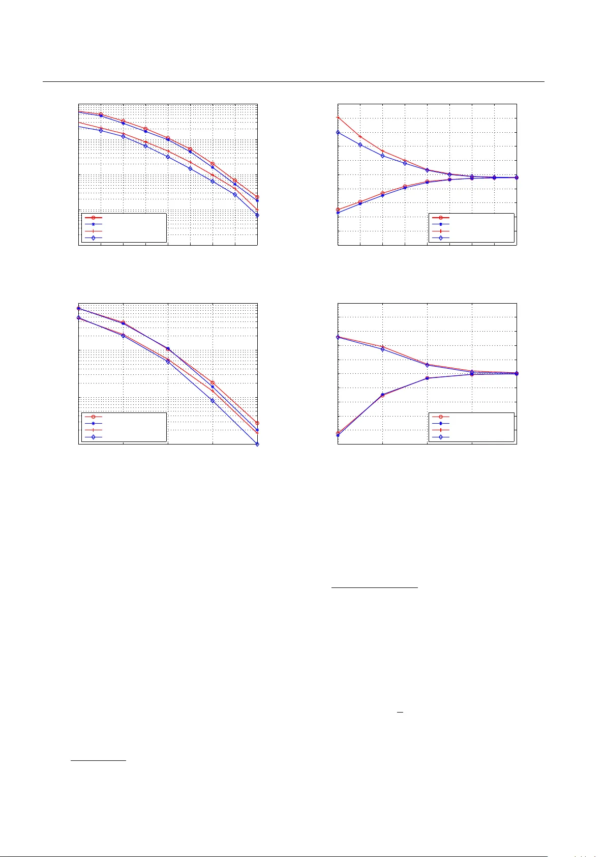
Journal of xxx man uscript No. (will b e inserted b y the editor) Segmen ted Successiv e Cancellation List P olar Deco ding with T ailored CR C Hua yi Zhou · Xiao Liang · Liping Li · Zaic hen Zhang · Xiaoh u Y ou · Ch uan Zhang ∗ Received: October 00, 2017 / Accepted: date Abstract As the first error correction codes pro v ably ac hieving the symmetric capacity of binary-input dis- crete memory-less c hannels (B-DMCs), p olar co des hav e b een recen tly c hosen b y 3GPP for eMBB control chan- nel. Among existing algorithms, CR C-aided successiv e cancellation list (CA-SCL) deco ding is fav orable due to its go o d p erformance, where CR C is placed at the end of the deco ding and helps to eliminate the inv alid can- didates b efore final selection. How ever, the go o d per- formance is obtained with a complexit y increase that is linear in list size L . In this pap er, the tailored CRC- aided SCL (TCA-SCL) deco ding is prop osed to balance p erformance and complexity . Analysis on ho w to c ho ose the prop er CR C for a giv en segmen t is prop osed with the help of virtual tr ansform and virtual length . F or fur- ther p erformance impro v ement, h ybrid automatic re- p eat request (HARQ) scheme is incorp orated. Numeri- cal results ha v e shown that, with the similar complex- it y as the state-of-the-art, the prop osed TCA-SCL and HAR Q-TCA-SCL schemes ac hieve 0 . 1 dB and 0 . 25 dB p erformance gain at frame error rate FER = 10 − 2 , re- sp ectiv ely . Finally , an efficien t TCA-SCL deco der is im- plemen ted with FPGA demonstrating its adv an tages o ver CA-SCL deco der. Hua yi Zhou · Xiao Liang · Zaichen Zhang · Xiaohu Y ou · Ch uan Zhang ∗ Lab of Efficient Arc hitectures for Digital-communication and Signal-processi ng (LEADS), National Mobile Communications Research Lab oratory , Southeast Universit y , Nanjing, China E-mail: { hyzhou, xiao liang, zczhang, xhyu, chzha ng } @seu.edu.cn ∗ corresponding author Liping Li Key Laboratory of Intelligen t Computing and Signal Process- ing of the MoE, Anhui Universit y , Hefei, China E-mail: liping li@ahu.edu.cn Keyw ords P olar codes · segmented CA-SCL · tailored CR C · HARQ · VLSI 1 Introduction P olar codes, prop osed by Arık an [1, 2], are considered as a breakthrough of co ding theory . It is shown that p olar co des can prov ably ac hieve the symmetric capac- it y of binary-input discrete memory-less c hannels (B- DMCs) [2]. Besides the capacity ac hieving p erformance, the asset of p olar co ding compared to the state-of-the- art (SO A) is its corresponding lo w-complexity deco ding algorithms. Therefore, p olar co des hav e b een adopted b y 3GPP for eMBB control channels. Though linear programming (LP) decoder [3], suc- cessiv e cancellation (SC) deco der, and b elief propaga- tion (BP) decoder [4, 5] hav e been prop osed for p olar co des, their p erformance is not comparable with maxi- m um lik eliho o d (ML) decoder. Th us, the breadth-first SC deco der named SC list (SCL) deco der, was pro- p osed b y [6, 7]. Cyclic redundancy c hec k (CR C), widely adopted for error detection, has b een pro v ed as a sim- ple and effective enabler for further performance im- pro vemen t with resp ect to SCL deco der. Numerical re- sults ha ve shown that, CRC-aided SCL (CA-SCL) de- co der [8] ac hiev es at least no w orse p erformance than the SOA turb o and low-densit y parity-c hec k (LDPC) deco ders [9]. Usually , CR C is placed at the end of de- co ding to eliminate in v alid candidates b efore final de- cision. The disadv an tages are: 1) Though has b etter p erformance than SCL decoder, CA-SCL deco der still suffers from time and space complexit y regarding the list size L . 2) F or in termediate candidates which ha v e already gone wrong, no early elimination could b e tak en 2 Hua yi Zhou et al. in time un til the deco ding end is reached, and the com- putation afterw ard is in v ain. T o address the complexit y and redundancy , [10] pro- p osed a segmented CA-SCL (SCA-SCL) deco der. A t the same time, [11] indep enden tly prop osed a parti- tioned CA-SCL (PSCL) deco der, whic h is similar as the SCA-SCL decoder but with a different partition metho d. Both deco ders divide code bits into segments and insert CR C bits in betw een, to rule out in v alid can- didates p er segment rather than to wait until the de- co ding ends. Thus, they can reduce redundancy while k eeping comparable p erformance as CA-SCL deco ders. Ho wev er, existing deco ders usually apply the same CRC length to the same nu mber of information or co de bits. Though conv enien t, those straigh tforw ard sc hemes fail to take the co de construction into consideration. It is not clear whether the existing uniform partition sc hemes are optimal and whether b etter p erformance can b e ac hieved with the same num b er of CRC bits. T o our b est knowledge, no existing literature has discussed the CR C distribution for SCA-SCL decoding, and its hardw are implemen tation. Analysing the CRC requiremen t by unequal-length segments and introduc- ing concepts of virtual tr ansform and virtual length , this paper dev otes itself in figuring out a tailored CA- SCL (TCA-SCL) deco ding of improv ed p erformance and low er complexity than SO A. An HARQ-TCA-SCL deco ding is prop osed for further p erformance improv e- men t. Contributions of this paper are: 1) Efficient CR C distribution is prop osed for the first time, showing p er- formance adv antage ov er SO A. 2) This pap er does not limit itself to specific deco der design, but prop oses a formal TCA methodology , whic h can b e readily applied to any existing SCA-SCL deco ders. 3) The efficient im- plemen tation methodology is also prop osed and verified with FPGA implemen tations. The remainder of the pap er is organized as follows. Section 2 reviews the preliminaries. Section 3 analyzes the SCA-SCL deco ders for p ossible refinemen t. The TCA- SCL deco ding is given in Section 4. The HAR Q-TCA- SCL deco ding is given in Section 5. Section 6 gives the p erformance and complexit y analysis of the prop osed deco ding sc hemes. Section 7 proposes a hardw are ar- c hitecture for TCA-SCL deco ding. FPGA implementa- tions are given in the same section. Finally , Section 8 concludes the en tire pap er. 2 Preliminaries 2.A P olar Co des Denote the input alphab et, output alphab et, and tran- sition probabilities of a B-DMC by X , Y , and W ( y | x ). With blo ck length N = 2 n , the information vector, en- co ded v ector, and received vector are u N 1 = ( u 1 , ..., u N ), x N 1 = ( x 1 , ..., x N ), and y N 1 = ( y 1 , ..., y N ). The p olar en- co ding is giv en by x N 1 = u N 1 G N = u N 1 B N F ⊗ n , (1) where G N and B N are the generation matrix and bit- rev ersal p ermutation matrix resp ectively , and F = [ 1 0 1 1 ]. T ransmitting channels b etw een x N 1 and y N 1 are W ( i ) N ( y N 1 , u i − 1 1 | u i ), deriv ed by chann el combining W N ( y N 1 | x N 1 ) = W N ( y N 1 | u N 1 G N ) (2) and c hannel splitting W ( i ) N ( y N 1 , u i − 1 1 | u i ) = P u N i +1 1 2 N − 1 W N ( y N 1 | x N 1 ) , i = 1 , ..., N . (3) Define I ( W ) as the symmetric capacit y . F or B-DMC W and δ ∈ (0 , 1), W ( i ) N p olarizes: as N go es to infin- it y via pow ers of 2, I ( W ( i ) N ) ∈ (1 − δ, 1] approac hes I ( W ) and I ( W ( i ) N ) ∈ [0 , δ ) approaches (1 − I ( W )). In ( N , K ) codes, the K most reliable c hannels with indices in information set A are chosen to transmit the K in- formation bits in u N 1 ; whereas the others, with indices in frozen set A c , transmit the ( N − K ) frozen bits. 2.B SC and SCL P olar Deco ders The SC p olar deco ding tree is a full binary tree. Fig. 1 sho ws a toy example for N = 8. F or eac h node at the n -th level, t w o p ossible choices are 0 and 1. Each set consisting of all the leaf no des is asso ciated with a unique estimated co deword ˆ u N 1 = ( ˆ u 1 , ˆ u 2 , ..., ˆ u N ). If i ∈ A c , ˆ u i = 0. Otherwise, the SC deco der computes its log-lik eliho o d ratio (LLR): L ( i ) N ( y N 1 , ˆ u i − 1 1 ) = log W ( i ) N ( y N 1 , ˆ u i − 1 1 | u i = 0) W ( i ) N ( y N 1 , ˆ u i − 1 1 | u i = 1) , (4) and generates its decision as ˆ u i = ( 0 , if L ( i ) N ( y N 1 , ˆ u i − 1 1 ) ≥ 0; 1 , otherwise . (5) The LLR up dating is conducted based on the tw o equations listed in Eq. (6). max ∗ denotes the Jacobi logarithm: max ∗ ( x 1 , x 2 ) ∆ = ln( e x 1 + e x 2 ) = max( x 1 , x 2 ) + ln(1 + e −| x 1 − x 2 | ) . (7) This recursive pro cess starts from each (sub-)tree’s ro ot and alw ays tra v erses the left branch before the righ t (Fig. 1). When the leaf level is reached, hard de- cision is made and returned to the paren t no de. As a greedy search algorithm, SC deco ding keeps only one path based on step-wise decision, with com- plexit y of O ( N log N ). How ev er, this single-candidate Segmented Successiv e Cancellation List Polar Deco ding with T ailored CRC 3 L (2 i − 1) N ( y N 1 , ˆ u 2 i − 2 1 | u 2 i − 1 ) = max ∗ ( L ( i ) N/ 2 ( y N/ 2 1 , ˆ u 2 i − 2 1 ,o ⊕ ˆ u 2 i − 2 1 ,e | u 2 i − 1 ) + L ( i ) N/ 2 ( y N N/ 2+1 , ˆ u 2 i − 2 1 ,e | 0) , L ( i ) N/ 2 ( y N/ 2 1 , ˆ u 2 i − 2 1 ,o ⊕ ˆ u 2 i − 2 1 ,e | ¯ u 2 i − 1 ) + L ( i ) N/ 2 ( y N N/ 2+1 , ˆ u 2 i − 2 1 ,e | 1)) , L (2 i ) N ( y N 1 , ˆ u 2 i − 1 1 | u 2 i ) = L ( i ) N/ 2 ( y N/ 2 1 , ˆ u 2 i − 2 1 ,o ⊕ ˆ u 2 i − 2 1 ,e | u 2 i − 1 ⊕ u 2 i ) + L ( i ) N/ 2 ( y N N/ 2+1 , ˆ u 2 i − 2 1 ,e | u 2 i ) . (6) Level 1 Level 2 Level 3 L N (2 i -1) L N (2 i ) L N /2 (2 i ) u 2 i -1 u 2 i u Level 0 Fig. 1 T ree illustration of SC deco ding process. metho d only guarantees the lo cal optimalit y , and will p ossibly result in incorrect result. T o this end, the SCL deco ding, which keeps a list of L surviv als, w as pro- p osed by [6, 7] indep endently . Fig. 2 illustrates the dif- ference b etw een SC and SCL algorithms. The complex- it y of SCL deco der is O ( LN log N ). At the i -th step, if i ∈ A , the SCL deco der splits each current path into t wo paths with b oth ˆ u i = 0 and ˆ u i = 1. Out of the 2 L paths, only the L b est ones are kept. Finally , the deco der chooses the b est path at the end of decoding pro cess. SC list deco ding ( L =2) SC decodi ng ...... ...... ...... 0 1 1 0 0 1 0 1 1 0 0 1 1 0 1 0 0 1 Fig. 2 SC deco ding and SCL deco ding with L = 2. CRC K = k + m Polar Encoder N bits W SCL De-CRC Failure Otherwise CA-S C L De coder k bits At least one path pass Output Fig. 3 CA-SCL p olar deco ding. 2.C CA-SCL P olar Deco der F or further impro vemen t, CA-SCL decoder introduces CR C as a detection to ol at the end of deco ding [8]. Il- lustrated in Fig. 3, CRC detector helps to decide which candidates are p ossibly correct b efore metric compar- ison. Here, m denotes the n um b er of CRC bits. The CR C-passed candidate with the largest metric v alue is c hosen as the final result. If no candidate passes the CR C detection, a deco ding failure is claimed. 3 Segmented CA-SCL Decoding Schemes In this section, we first introduce t wo SCA-SCL decod- ing schemes, then prop ose a refined version. Without loss of generality , the (1024 , 512) code [2] is emplo y ed as a running example, whose p olarization is in Fig. 4. Here W is a BEC with erasure probabilit y = 0 . 5, I ( W ( i ) N ) is computed b y: I ( W (2 i − 1) N ) = I ( W ( i ) N/ 2 ) 2 , I ( W (2 i ) N ) = 2 I ( W ( i ) N/ 2 ) − I ( W ( i ) N/ 2 ) 2 ; (8) with I ( W (1) ) = 1 − . The blue stars in Fig. 4 denote the information bits, whereas the red p oints denote the frozen bits. 1 256 512 768 1024 Channel index 0 0.1 0.2 0.3 0.4 0.5 0.6 0.7 0.8 0.9 1 Symmetric capacity Frozen bits Information bits Fig. 4 Channel p olarization for a BEC with = 0 . 5 . 3.A Comparison of Differen t Segmented Schemes T o the authors’ b est knowledge, there are t w o segmen ted CR C-aided SCL metho ds. The PSCL scheme prop osed 4 Hua yi Zhou et al. in [11] aims to reduce memory consumption, and ap- plies uniform partitions to co de bits for implemen ta- tion conv enience. The hardw are reduction comes at the cost of some p erformance loss compared to the con v en- tional CA-SCL algorithm and alw ays forces the n umber of candidate paths to 1 after each CR C. The SCA-SCL sc heme prop osed in [10] aims to reduce b oth the time and space complexity . Uniform segmen ts are applied to information bits and CR C is employ ed as a to ol to elim- inate deco ding redundancy without harming the perfor- mance. PSC L : u n i fo r m p a r ti ti o n o f c o d e b i ts T 1 T 2 T 3 T 4 SC A - SC L : u n i fo r m p a r ti ti o n o f i n fo r m a ti o n b i ts S 1 S 2 S 3 S 4 D i s tr i b u ti o n o f c o d e b i ts D i s tr i b u ti o n o f c o d e b i ts F r o z e n b i t s F r o z e n b i t s I n f o r m a t i o n b i t s I n f o r m a t i o n b i t s F r o z e n b i t s I n f o r m a t i o n b i t s F r o z e n b i t s I n f o r m a t i o n b i t s Fig. 5 Different segmented deco ding sc hemes with P = 4. Let P denote the n umber of segmen ts. F or PSCL deco der, the index set of Segment- i is T i (1 ≤ i ≤ P ). | · | denotes the cardinalit y of one set. W e hav e X P i =1 | T i | = N , and | T i | = N /P . (9) F or SCA-SCL deco der, the index set of Segment- i is S i (1 ≤ i ≤ P ). we hav e X P i =1 | S i | = N , and | S i ∩ A| = K/P . (10) One simple example of P = 4 is illustrated in Fig. 5. Theoretically , b oth sc hemes are similar but differ in the partition metho ds. PSCL deco ding employs uni- form co de bit partition, whic h is implementation friendly . Ho wev er, since only one candidate can survive after eac h CRC, small p erformance degradation is exp ected, esp ecially in low SNR region. SCA-SCL decoding em- plo ys uniform information bit partition, whic h can k eep the p erformance as CA-SCL deco ding while successfully reducing the space and time complexity . This adv antage comes from the deco ding flexibility . How ever, the flexi- bilit y will make the implementation more complicated. 3.B PSCL with Early T ermination The first observ ation is that, b oth schemes apply the same CR C to the uniformly partitioned segments. With- out lo oking into the symmetric capacity of each binary c hannel, this straightforw ard sc heme ma y not be opti- mal. The second observ ation is that b oth schemes ha ve their o wn merits, it would b e smarter to merge them together. In other w ords, it is estimated that we can prop ose a new approach which is b oth implementation friendly and adaptiv e. One simple mixture of b oth schemes is to in tro duce early termination to PSCL deco ding. Ho wev er, this sim- ple com bination may not b e reasonable in certain cases. Fig. 6 giv es an example with P = 4. Sho wn in Fig. 7, for the (1024 , 512) code with m = 32, the information lengths of four segments are 20, 123, 156, and 245, re- sp ectiv ely . If uniform CR C bits are employ ed, the first segmen t has | T 0 1 | = | T 1 | − | C 1 | = 12 information bits and the last segment has | T 0 4 | = | T 4 | − | C 4 | = 237 in- formation bits. It is unreasonable to use the same 8-bit CR C to b oth the 12-bit and 237-bit segments. T o this end, the TCA-SCL deco ding is prop osed in the follow- ing section. 4 CA-SCL Deco ding with T ailored CRC In this section, we first discuss how to measure the requiremen t of CRC bits for differen t segments. Then the concepts of virtual transform and virtual length are in tro duced. A visualization method of p olarized chan- nel’s symmetric capacity is also prop osed. The detailed TCA-SCL decoding is finally proposed. It should b e noted that though the TCA-SCL deco ding is based on uniform partition of co de bits, it can b e readily applied to other uniform or non uniform partition schemes. 4.A Requiremen t of CRC Length for Polar Co des Assume a total of m CRC bits are a v ailable and are divided into P segments C 1 , C 2 , . . . , C P . It may not b e suitable to set | C 1 | = | C 2 | = . . . = | C P | for P segments with differen t lengths. Ho w to measure the requiremen t of the CRC length for each segment is critical. T o the authors’ best knowledge, no literature has addressed this sp ecific problem. T o maintain the same error detec- tion capability in the situation of indep enden t c hannels, it is concluded that longer sequence requires more CR C bits [12]. How ever, this conclusion do es not suit p olar co des b ecause the reliabilit y of differen t c hannels are differen t. A reasonable measurement on requirement of CR C length should tak e b oth sequence length and sym- metric capacity in to account. In the following, concepts of virtual transform and virtual length are prop osed to this end. 4.B Virtual T ransform and Virtual Length Including CRC bits, we alwa ys pic k the K + m most reliable bits out of N based on the symmetric capacity Segmented Successiv e Cancellation List Polar Deco ding with T ailored CRC 5 k bits PSCL Decodin g with Early Te r min ation K = k + m Polar Encoder N bits W Segme nt SCL De-CRC Failure Pass Output Segme nt SCL De-CRC Pass Segment SCL De-CRC Pass Segme nt SCL De-CRC Pass En-CRC Segmented by code bits Fail Fail Fail Fail Fig. 6 PSCL deco ding with early termination. T ' 1 C 1 T ' 2 C 2 T ' 4 C 3 T ' 3 C 4 T 1 T 2 T 3 T 4 Fig. 7 The CRC allo cation of PSCL ( N = 1024, K = 512). I ( W ( i ) N ) with i ∈ A 0 . A 0 is the new information set including CRC bits, and |A 0 | = K + m . Calculate ¯ I as follo ws: ¯ I = 1 K + m X i ∈A 0 I ( W ( i ) N ) . (11) Definition 1 Virtual T r ansform T o op er ate the vir- tual tr ansform, we first c alculate I 0 ( i ) : I 0 ( i ) = ¯ I /I ( W ( i ) N ) . (12) The virtual value of the channel is J ( i ) = 1 + ( I 0 ( i ) − 1) 2(1 − ¯ I ) , if I 0 ( i ) ≥ 1; 1 − (1 − I 0 ( i )) 2(1 − ¯ I ) , if I 0 ( i ) < 1 . (13) Definition 2 Virtual L ength The summation of J ( i ) in the k -th se gment is its virtual length: v l k = X i ∈{ T k ∩A 0 } J ( i ) . (14) The CR C allo cation is given by | C 1 | : . . . : | C P | = adjust m × v l 1 P P i =1 v l i , . . . , m × v l P P P i =1 v l i ! , (15) where adjust( · ) is a function whic h adjusts the allo- cation results to near in tegers and takes the follow- ing steps: 1) find an unmarked k which has minim um | R OUND( m × v l k P P i =1 v l i ) − m × v l k P P i =1 v l i | , then mark k and set | C k | = R OUND( m × v l k P P i =1 v l i ); 2) rep eat step 1) for ( P − 2) times; 3) Assume the left unmarked index is k 0 . Set | C k 0 | = m − P i 6 = k 0 | C i | , where 1 ≤ i ≤ P . 4.C Visualization of Channel Symmetric Capacit y Before we give more details of the prop osed TCA-SCL deco ding, one visualization metho d of symmetric ca- pacit y is prop osed for easy understanding and illustra- tion. In this visualization, the gradien t colors from iri- descence are used to demonstrate the symmetric ca- pacit y of eac h channel. According to the legend, the more symmetric capacit y approac hing 1 (0), the more batho c hromic (hypsochromic) it will be. Fig. 8(a) sho ws the visualization for p olar co des with N = 64. Example 1 F or (1024 , 512) p olar c o des with 32 CRC bits, visualization of c o de bits is given in Fig. 8(b). The visualization of 512 information bits is given in Fig. 8(c). F or TCA-SCL de c o ding, set P = 4 . A c c or d- ing to Definition 2, the r atio of virtual lengths is: v l 1 : v l 2 : v l 3 : v l 4 = 3 . 54 : 9 . 84 : 10 . 91 : 7 . 70 , (16) which is il lustr ate d by Fig. 8(d). Then the CR C al lo c a- tion is obtaine d ac c or ding to Eq. (15): | C 1 | : | C 2 | : | C 3 | : | C 4 | = 3 : 10 : 11 : 8 . (17) The r efine d CRC al lo c ation b ase d on virtual length is given in Fig. 8(e). Remark 1 Gener al ly sp e aking, the hypso chr omic p art in the visualization chart mainly c ontributes to the vir- tual length. The mor e hypso chr omic se gment r e quir es mor e CR C bits. This refined SCA-SCL deco ding based on virtual length is named TCA-SCL decoding. Details of TCA- SCL deco ding is giv en as follo ws. The corresp onding p erformance and implemen tation are discussed in Sec- tion 6 and Section 7. 4.D T ailored CA-SCL Deco ding The detailed tailored CA-SCL deco ding is given in this subsection. F or TCA-SCL enco ding, we set P segments 6 Hua yi Zhou et al. (a) Visualization of symmetric capacity for co de bits ( N = 64). (b) Visualization of symmetric capacity for co de bits ( N = 1024). (c) Visualization of symmetric capacity for information bits ( N = 1024, K = 512). 10 3 11 8 (d) F our segments of information bits with virtual lengths ( N = 1024, K = 512). T ' 1 C 1 T ' 2 C 2 T ' 4 C 3 T ' 3 C 4 T 1 T 3 T 4 T 2 (e) The CRC allo cation of TCA-SCL ( N = 1024, K = 512). Fig. 8 Visualization illustration of symmetric capacity . and perform the virtual transform to obtain the cor- resp onding virtual lengths. Then w e allocate the CRC bits according to the ratio of virtual lengths b efore p o- lar enco ding. Here, addCR C( · ) is function which p erforms Eq. (15). F unction encoder( · ) performs con ven tional polar encod- ing. F or TCA-SCL deco ding, SCL decoding with early termination is p erformed as follows. Here, the function SCL 0 ( · ) is the SCL deco ding for Segment- j . Define U i as the the output paths set of SCL( · ) in i -th segmen t. Define passCRC( · ) as the function whic h chec ks if at least one path of U i can pass the CRC. If one or more than one path can pass the CR C, the path with the largest metric of them is c hosen to refresh ˆ u N 1 . 5 TCA-SCL Deco ding with HARQ Besides early termination, the prop osed TCA-SCL de- co ding can also w ork in a HARQ w a y when segmented CR C fails. HAR Q has been widely used in dela y insensi- tiv e comm unication systems for a capacit y-approac hing throughput [13–15]. Recen tly , HARQ has been consid- ered for p olar deco ding. [16] in tro duced a HARQ scheme Algorithm 1 TCA-SCL Polar Enco ding Input: u N 1 , I ( W ( i ) N ), N , K , m , P . 1: Set P segments; 2: ¯ I = 1 K + m P i ∈A 0 I ( W ( i ) N ); 3: for i = 1; i < = N ; i + + do 4: I 0 ( i ) = ¯ I /I ( W ( i ) N ); 5: if I 0 ( i ) ≥ 1 then 6: J ( i ) = 1 + ( I 0 ( i ) − 1) 2(1 − ¯ I ) ; 7: else 8: J ( i ) = 1 − (1 − I 0 ( i )) 2(1 − ¯ I ) ; 9: end if 10: end for 11: for k = 1; k < = P ; k + + do 12: v l k = P i ∈{ T k ∩A 0 } J ( i ); 13: end for 14: addCR C( u N 1 , v l 1 , v l 2 , .., v l P ); 15: x N 1 = enco der( u N 1 ). Output: x N 1 . based on a class of rate-compatible polar codes con- structed b y performing punctures and repetitions us- ing punctured p olar co ding [17]. An incremen tal redun- Segmented Successiv e Cancellation List Polar Deco ding with T ailored CRC 7 Algorithm 2 TCA-SCL Polar Deco ding Input: y N 1 , N , P , L . 1: for i = 1; i < = P ; i + + do 2: U i = SCL 0 ( y N 1 , i, L ); 3: if passCR C( U i ) = false then 4: break ; 5: end if 6: refresh ˆ u N 1 b y the surviv al path in U i ; 7: end for Output: ˆ u N 1 . dancy HARQ (IR-HAR Q) sc heme via puncturing and extending of p olar co des is prop osed in [18]. Both al- gorithms use punctured patterns to suit differen t rates. Ho wev er, puncturing causes a p erformance loss and needs h ybrid decoding schemes to remedy it with high com- plexit y . And IR-HARQ sc heme needs to retransmit frozen bits one b y one after transmitting K information bits. Therefore, the deco ding complexit y of IR-HARQ is O ( N 2 log N ), whic h is high for a large N . T o ov ercome this issue, w e give a HARQ-TCA-SCL sc heme based on TCA-SCL deco ding. When a segmen t deco ding failure o ccurs, the system resends the sp ecific segmen t and merges the new information bits with the old ones by maximum ratio combining (MR C). F or dif- feren t segmen ts sharing the same SNR, decoder can ap- ply linear sup erp osition to obtain the av erage v alue. As the n umber of segment retransmission go es up, the noise p o wer conv erge to zero, which helps to impro ve the p erformance effectiv ely . Segm ent SCL De-C RC i = i +1 Pass HARQ-TCA-SCL decoding i ุ T No Failur e Next segme nt Finish decoding Outpu t Yes Retra nsmit and com bine K = k + m Polar Encoder N bits W k bits En-CRC Segme nted by tota l bits No Yes Fail Fig. 9 Prop osed HAR Q-TCA-SCL decoding scheme. The prop osed HAR Q-TCA-SCL scheme is illustrated in Fig. 9. Let i denotes the current num ber of times a transmission attempted, T denotes the maximum re- transmission times, and j ( ≤ P ) denotes the current p osition of the segments. The details of HARQ-TCA- SCL sc heme are listed as follows: W e initialize i = 1 for the HARQ-TCA-SCL de- co ding, then p erform the SCL decoding for Segment- j (function SCL 0 ( · )) and obtain CRC results on eac h sur- viv al path at the end of segmen t SCL deco ding. If at least one path can pass CR C, we sav e the path with the Algorithm 3 HARQ-TCA-SCL Polar Deco ding Input: y N 1 , T , P , L 1: i = 1; 2: for j = 1 to P do 3: mark = false; 4: while i < T and mark = false do 5: U j = SCL 0 ( y N 1 , j, L ); 6: mark = passCRC( U j ); 7: if mark = false then 8: i = i + 1; 9: Retransmit and combine Segment- j ; 10: end if 11: end while 12: if mark = false then 13: break ; 14: end if 15: refresh ˆ u N 1 b y the surviv al path in U j ; 16: end for Output: ˆ u N 1 highest probabilit y and mo ve to the next segmen t. Oth- erwise, we update i to i + 1, com bine Segmen t- j with the retransmitted part and the old ones, redo the TCA- SCL decoding. Algorithm terminates with a deco ding failure if i = T . 6 Performance and Complexit y Analysis 6.A P erformance Analysis In this subsection, p erformance comparison b etw een differen t algorithms is given with binary-input addi- tiv e white Gaussian noise c hannels (BI-A W GNCs). Dif- feren t code lengths, rates, and partition schemes are considered: for Fig. 10(a), w e ha ve N = 64, K = 36, m = 8, and P = 2; for Fig. 10(b), w e ha ve N = 1024, K = 512, m = 32, and P = 4. The information set A is selected according to [2, 19]. W e use corresp onding hex v alue to represen t CR C p olynomial. F or example, a CRC-4 detector with p olynomial g ( D ) = D 4 + D + 1 is described as CR C-4 (0x9) in this pap er (the ‘+1’ is implicit in the hex v alue). F or (64 , 36) co de, w e set 2 copies of CR C-4 (0x9) for (HAR Q-)PSCL scheme, and CR C-5 (0x12) and CR C-3 (0x5) for (HARQ-)TCA-SCL sc heme. F or (1024 , 512) co de, w e set 4 copies of CRC-8 (0xA6) for (HARQ-)PSCL sc heme, and CRC-3 (0x5), CR C-10 (0x327), CR C-11 (0x583), and CRC-8 (0xA6) for (HAR Q-)TCA-SCL scheme. All the CRC detectors are with the b est CRC generation polynomial suggested b y [12]. According to Fig. 10, compared with the PSCL sc heme, the prop osed TCA-SCL sc heme has a 0 . 1 dB p erfor- 8 Hua yi Zhou et al. 1 1.5 2 2.5 3 3.5 4 4.5 5 10 −4 10 −3 10 −2 10 −1 10 0 E b / N 0 (dB) FER PSCL TCA−SCL HARQ−PSCL ( T = 3) HARQ−TCA−SCL ( T = 3) (a) ( N = 64, K = 36, m = 8, P = 2) 1 1.5 2 2.5 3 10 −3 10 −2 10 −1 10 0 E b / N 0 (dB) FER PSCL TCA−SCL HARQ−PSCL ( T = 3) HARQ−TCA−SCL ( T = 3) (b) ( N = 1024, K = 512, m = 32, P = 4) Fig. 10 FER comparison of (HARQ-)TCA-SCL and (HARQ-)PSCL sc hemes. mance gain when FER = 10 − 2 for both (64 , 36) and (1024 , 512) co des. The HARQ-TCA-SCL ( T = 3) scheme in tro duces a 0 . 25 dB and 0 . 13 dB gain o v er the HARQ- PSCL scheme when frame error rate FER = 10 − 2 for (64 , 36) and (1024 , 512) co des, resp ectiv ely . 6.B Complexit y Analysis Define the pro duct of the actual deco ding length and list size as the av erage list size. Since the av erage com- putational complexity is prop ortional to the a v erage list size, here we analyze the av erage list sizes of TCA-SCL and HARQ-TCA-SCL decoders denoted b y ¯ L T and ¯ L H , resp ectiv ely . Assume the total frame num b er is F , and the decoder ends at the P i -th segmen t of the i -th frame. F or the TCA-SCL deco der, ¯ L T can b e calculated as ¯ L T = L × P F i =1 P i P × F . (18) 1 1.5 2 2.5 3 3.5 4 4.5 5 1 1.2 1.4 1.6 1.8 2 2.2 2.4 2.6 2.8 3 Average List Size E b / N 0 (dB) PSCL TCA−SCL HARQ−PSCL ( T = 3) HARQ−TCA−SCL ( T = 3) (a) ( N = 64, K = 36, m = 8, P = 2) 1 1.5 2 2.5 3 1 1.2 1.4 1.6 1.8 2 2.2 2.4 2.6 2.8 3 Average List Size E b / N 0 (dB) PSCL TCA−SCL HARQ−PSCL ( T = 3) HARQ−TCA−SCL ( T = 3) (b) ( N = 1024, K = 512, m = 32, P = 4) Fig. 11 Average list sizes of (HARQ-)TCA-SCL and (HARQ-)PSCL sc hemes. Supp ose the i -th frame is retransmitted R i times (0 ≤ R i ≤ T ). F or the HARQ-TCA-SCL deco der, ¯ L H is cal- culated as ¯ L H = L × P F i =1 ( P i + R i ) P × F . (19) F or low SNR, thanks to the early termination ¯ L T is small due to high error rate. On the other hand, a larger num b er of retransmissions leads to a higher ¯ L H for HAR Q-TCA-SCL decoder. As SNR increases, ¯ L T and ¯ L H con verge to L : 1) TCA-SCL deco der is more lik ely to finish the deco ding pro cess, and 2) the retrans- mission time of HARQ-TCA-SCL deco der conv erges to 0. It should b e noted that, according to Eq. (18) and (19) 0 ≤ ¯ L H − ¯ L T ≤ L P T . Sho wn in Fig. 11, (HAR Q-)TCA-SCL sc heme has the same complexity as (HARQ-)PSCL scheme. The HAR Q-TCA-SCL scheme has 50 . 3% and 38 . 5% higher complexit y than the PSCL scheme at SNR = 1 . 5 dB Segmented Successiv e Cancellation List Polar Deco ding with T ailored CRC 9 for (64 , 36) and (1024 , 512) co des, resp ectively . As SNR go es up, the complexity of HAR Q-TCA-SCL scheme tends to be as same as the PSCL scheme asymptotically with b etter p erformance. 7 Efficient TCA-SCL Decoder Architectures T o facilitate the application of the prop osed TCA-SCL deco der, efficient arc hitectures and FPGA implementa- tions are prop osed in this section and are also giv en to demonstrate its merits. Since hardware consump- tion and decoding latency are tw o main concerns of SCL family deco der, the prop osed arc hitecture aims to ac hieve a go o d balance in b etw een. The HARQ-TCA- SCL deco der can also b e designed similarly . 7.A Hardw are Consumption Analysis 7.A.1 F ul l Mo dule TCA-SCL Ar chite ctur e In this subsection, a full module TCA-SCL arc hitecture is prop osed, which is mainly based on the conv entional folded SC architecture proposed in [20]. The arc hitec- ture for full mo dule TCA-SCL deco der is illustrated in Fig. 12. It divides all mixed no de mo dules (MNs) in to n = log 2 N stages, and eac h MN implements t wo t yp es of calculations mentioned in Eq. (6). According to the conclusions in [20], for an N -bit SC decoder, ( N − 1) MNs are required. F or an N -bit CA-SCL de- co der, L ( N − 1) MNs are emplo yed. Theorem 1 F or one P -se gmente d TCA-SCL de c o der with list L , the total numb er of MNs is MN total = N − L + ( L − 1) N P . (20) Pr o of F or the giv en deco der, its MNs can b e catego- rized in to t wo parts. The first part includes Stages 1 to log 2 P . The second part includes Stages (log 2 P + 1) to n . It should b e noted that since N is p o wer of 2, log 2 P is alw ays an integer. Since each segment outputs only one candidate, the first part ob eys SC deco ding rule, and list size L is not necessary . The num ber of MNs is MN 1 = P log 2 P i =1 N / 2 i − 1 = N − N P . (21) The second part ob eys CA-SCL deco ding rule with- out considering the fine-gain sc heduling. The num b er of MNs is MN 2 = L P n i =log 2 P +1 N / 2 i − 1 = L ( N P − 1) . (22) Since the memory blo ck corresp onds to MNs, the memory complexit y is as follows Corollary 1 Assume the quantization length for the LLR message is q , the memory bits r e quir e d ar e mem total = q × MN total = q N − L + ( L − 1) N P . (23) The list core (LC) mo dule in Fig. 12 mainly imple- men ts the sorting op eration. In order to reduce b oth the sorting latency and complexit y , the efficient distributed sorting (DS) prop osed in [21] is emplo yed here. 7.A.2 F olde d Mo dule TCA-SCL Ar chite ctur e Thanks to the early termination scheme, the prop osed full mo dule arc hitecture for TCA-SCL deco ding is mem- ory efficient compared to conv en tional CA-SCL deco d- ing. Ho wev er, the hardware utilization ratio (HUR) of MNs is very lo w. Borrowing the fine-folding idea pro- p osed in [21, 22], this pap er then prop oses the folded mo dule TCA-SCL architecture for higher HUR. W e set up a sub-deco der with (2 d n/ 2 e − 1) L MNs for Stage 1 to d n/ 2 e . Stage ( d n/ 2 e + 1) to n can also b e im- plemen ted by this sub-deco der in a time-multiplexing manner. Fig. 13 giv es an example of a even n , Stage 1 and Stage n/ 2 + 1, Stage 2 and Stage n/ 2 + 2, ..., Stage n/ 2 and Stage n are time-multiplexing. If n is o dd, Stage 1 and Stage ( n + 1) / 2 + 1, Stage 2 and Stage ( n + 1) / 2 + 2, ..., Stage ( n + 1) / 2 − 1 and Stage n are time-m ultiplexing, and Stage ( n + 1) / 2 uses the last stage alone. Parameter j in Fig. 13 denotes the cur- ren t folding order. How ev er, the characteristics in Sec- tion 7.A.1 which helps to reduce the complexity of the first log 2 P stages could not b e employ ed here, b ecause folding tec hnique is based on uniform hardware. The complexit y is Theorem 2 F or one folde d mo dule TCA-SCL de c o der with list L , the total numb er of MNs is MN total = (2 d n/ 2 e − 1) L. (24) Pr o of When implementing Stage 1 to d n/ 2 e , all the in- put and output multiplexers choose mo de ‘0’. 2 d n/ 2 e +1 executions are required to output 2 d n/ 2 e +1 L LLRs for Stage d n/ 2 e . F or P -segmented deco der, if log 2 P ≥ d n/ 2 e , (2 d n/ 2 e − 1)( L − 1) MNs are idle during this deco d- ing stage. Otherwise, according to Eq. (21), (2 d n/ 2 e − 2 d n/ 2 e P )( L − 1) MNs are idle. Therefore, (2 d n/ 2 e − 1) L MNs are sufficien t. When implementing Stage ( d n/ 2 e + 1) to n , all the input and output multiplexers choose mo de ‘1’. Since 2 d n/ 2 e +1 L LLRs b ecome the input of the sub-deco der, no MN is idle during this stage. Therefore, the total n umber of MNs is (2 d n/ 2 e − 1) L . Theorem 3 Assume the quantization length for the LLR message is q , the memory bits r e quir e d by the folde d 10 Hua yi Zhou et al. M N I I U S U M M N I I Stag e 2 Stag e n -1 Stag e n ˆ - i u 2 1 ˆ i u 2 ... ... MN M N I MN M N I MN LC U S U M U SUM M N I I MN M N I I MN Stag e 3 ... ... MN MN MN MN MN MN MN MN MN MN ... MN MN Stag e 1 Update M N I I CRC1 M N I I CRC2 M N I I CRC P Memory Update C MN Mixed Node LC List Core Multiplexer Comparator C CRC CRC detector L Parallel Modules U S U M U S U M (1) 1 1 ( ) L y (1) 1 2 ( ) L y (1) 1 3 ( ) L y (1) 1 4 ( ) L y (1) 1 3 ( ) N L y - (1) 1 2 ( ) N L y - (1) 1 1 ( ) N L y - (1) 1 ( ) N L y ... 0 1 0 1 P -1 0 1 0 1 ... P -1 ... ... Fig. 12 Architecture for full module TCA-SCL deco der. 1 0 1 0 M N I I U S U M M N I I Stag e 1 or Stag e n /2+1 Stag e n /2-1 or Stag e n -1 Stag e n /2 or Stag e n ˆ - i u 2 1 ˆ i u 2 MN LC Mixed Node List Core ... ... MN M N I MN M N I MN LC U S U M U SUM M N I I MN M N I I MN Stag e 2 or Stag e n /2+2 ... ... U S U M U S U M L Parallel Modules Update M N I I CRC1 M N I I CRC2 M N I I CRC P Memory Update Multiplexer CRC CRC detector C C Comparator M N I MN M N I MN 1 0 M N I I LLR 0 1 0 1 0 1 0 1 0 1 0 1 0 1 0 1 0 1 0 1 0 1 0 1 M N I MN M N I MN 0 1 0 1 0 1 0 1 0 1 0 1 0 1 0 1 0 1 0 1 0 1 0 1 (1) 1 ( 1) 1 ( ) j N L y - + (1) 1 ( 1) 2 ( ) j N L y - + (1) 1 ( 1) 3 ( ) j N L y - + (1) 1 ( 1) 4 ( ) j N L y - + (1) 1 3 ( ) j N L y - (1) 1 2 ( ) j N L y - (1) 1 1 ( ) j N L y - (1) 1 ( ) j N L y ... LLR LLR message 0 1 0 1 0 1 0 1 P -1 ... P -1 ... ... Fig. 13 Architecture for folded TCA-SCL deco der ( n is even). T able 1 Implemen tation Analysis for Different Schemes Sc hemes Mixed no de # Memory (bit) Latency (clo ck cycles) LLRs Outputs CA-SCL ( N − 1) L 2046 ( N − 1) Lq 2046 q ( K + m ) L 1088 T CA TCA-SCL (SF) N − L + ( L − 1) N P 1278 ( N − L + ( L − 1) N P ) q 1278 q ( K + m ) L 1088 T CA + ( T 1 + ... + T ( P − 1) ) L TCA-SCL (DF) N − L + ( L − 1) N P 1278 ( N − L + ( L − 1) N P ) q 1278 q 2( K + m ) L 2176 T CA + P log 2 P − 2 P + 2 FTCA-SCL (SF) ( √ N − 1) L 62 ( N − L + ( L − 1) N P ) q 1278 q ( K + m ) L 1088 T CA + F + ( T 1 + ... + T ( P − 1) ) L FTCA-SCL (DF) ( √ N − 1) L 62 ( N − L + ( L − 1) N P ) q 1278 q 2( K + m ) L 2176 T CA + F + P log 2 P − 2 P + 2 mo dule TCA-SCL ar chite ctur e is mem total = q N − L + ( L − 1) N P . Pr o of The folded design only reduces the complexit y of MNs. How ever, the memory complexit y stays the same as the full mo dule TCA-SCL arc hitecture. T able 2 gives FPGA results in accordance with Theo- rem 3. 7.B Timing Analysis 7.B.1 Single F r ame Scheme As Fig. 12 sho wn, the decoding pro cess for TCA-SCL has the following steps: 1) In Segmen t j , MNs complete the main deco ding in Eq. (6). The 2 L LLRs corresp ond to ˆ u i for eac h path. 2) 2 L LLRs are input to the LC mo dule. DS metho d [21] is employ ed to select the b est L paths. 3) The memory is up dated and partial sum v ector ˆ u sum is calculated for ˆ u i +1 . 4) W e repeat the ab o ve steps to get the L paths for ˆ u ( N P j − 1) 1 . Then, ˆ u N P j is directly chosen as ‘0’ or ‘1’ for each path without de- co ding. After that, we input information bits in ˆ u N P j N P ( j − 1) for 2 L paths to CRC j to pick up the only path for Seg- men t j + 1. CRC is implemented with linear feedback shift register (LFSR) [23], and determines the coeffi- cien t of xor . Shown in Fig. 12, P CRC mo dules are emplo yed. It should b e noted that here CRC j tak es care of 2 L paths in serial manner. Admittedly , designers can pro cess 2 L with parallel CRCs. Considering the simple Segmented Successiv e Cancellation List Polar Deco ding with T ailored CRC 11 SE G1 S E G2 BL O CK1 BL O CK2 SE G1 SE G2 F r a m e 1 F r a m e 2 C R C c loc k c yc l e s Dyna m ic TC A -S C L de c oding c lock c yc les (a) TCA-SCL p olar deco der with SF scheme. SE G3 Dyna m ic TC A -S C L de c oding c lock c yc les C R C c loc k c yc l e s SE G4 BL O CK1 BL O CK2 F r a m e 1 SE G2 SE G3 SE G 4 F r a m e 2 (b) TCA-SCL p olar deco der with DF scheme. Fig. 14 Timing analysis for TCA-SCL p olar deco der with SF and DF schemes. CR C and its short pro cessing time, serial manner is emplo yed here. The sc heduling of this single frame (SF) sc heme is sho wn in Fig. 14(a). The latency of SF TCA-SCL de- co der is Theorem 4 Assume the latency of CA-SCL is T CA clo ck cycles. The latency for CRC i is T i . F or one SF P - se gmente d TCA-SCL de c o der with list L , the de c o ding latency is T SF = T CA + 2 L ( T 1 + ... + T ( P − 1) ) . (25) Pr o of After c hecking all 2 L paths of Segment i , the deco der selects one path and b egins to deco de Segment ( i + 1). In SF sc heme, segmented CR C scheme increases latency for serial c hecking of Segment i T crc i = 2 LT i . (26) In SF scheme, c hecking Segment P of F rame 1 and deco ding Segmen t 1 of F rame 2 can b e done at the same time. Since the chec king time is shorter than deco ding time, the latency increase is T inc = 2 L X P − 1 i =1 T i . (27) No w the pro of is immediate. F olded mo dule TCA-SCL deco der can also work in the prop osed SF sc heme. Corollary 2 Assume the folding te chnique intr o duc es F extr a clo ck cycles p er fr ame, the latency of SF folde d mo dule TCA-SCL de c o der is T SF = T CA + F + 2 L ( T 1 + ... + T ( P − 1) ) . (28) 7.B.2 Double F r ame Scheme SF decoding in troduces 2 L ( T 1 + ... + T ( P − 1) ) extra clo ck cycles p er frame. During CRC detection, all MNs are idle and HUR is therefore low. T o this end, the double frame (DF) sc heme is prop osed. The main idea of DF is shown in Fig. 14(b). Two frames are deco ded simultaneously in an interlea ved manner: when F rame 1 chec ks (decodes) its Segment i , F rame 2 deco des (chec ks) its Segment i ( i − 1). Since b oth frames share the same architecture, every time a new segment is deco ded, all LLRs in memory b elong to the other frame. If we keep the decoding latency of eac h frame the same as CA-SCL deco der, Stage 1 to (log 2 P − 1) need an extra memory blo ck of q ( N 2 + N 4 + ... + 2 N P ) bits to sav e LLRs, which is not appreciated by hardw are design. If no extra memory is av ailable, each new segment b egins its deco ding with Stage 1. In this w ay , DF sc heme still requires a memory blo c k of q N − L + ( L − 1) N P bits with slightly increased la- tency . F or DF full mo dule TCA-SCL deco der: Theorem 5 F or one DF P -se gmente d TCA-SCL de- c o der with list L , the de c o ding latency is T DF = T CA + P log 2 P − 2 P + 2 . (29) Pr o of F or the interlea ved manner in Fig. 14(b), the la- tency of eac h segment is T seg i = max { T dec i , T crc i } , (30) where T dec i denotes the SCL deco ding latency for Seg- men t i , which includes SC deco ding and DS. According 12 Hua yi Zhou et al. to [21], the DS latency for Segment i is appro ximately 2 LT i , therefore T dec i > 2 LT i . (31) Since T crc i = 2 LT i T DF = X P i =1 T seg i = X P i =1 T dec i . (32) It is b elieved that there are 2 i segmen ts, whic h could calculate from Stage ( i + 1), now calculates from Stage 1 and in tro duce latency of i · 2 i . Therefore, the decoding increased latency is T inc = X log 2 P − 1 i =1 i · 2 i = P log 2 P − 2 P + 2 . (33) No w the pro of is immediate. F olded mo dule TCA-SCL deco der can also work in the prop osed DF sc heme with the following latency . Corollary 3 Assume the folding te chnique intr o duc es F extr a clo ck cycles p er fr ame, the latency of DF folde d mo dule TCA-SCL de c o der is T DF = T CA + F + P log 2 P − 2 P + 2 . (34) T able 1 shows comparison betw een fiv e differen t sc hemes: CA-SCL deco der, SF (DF) full mo dule TCA-SCL de- co ders, and SF (DF) folded mo dule TCA-SCL deco ders. According to Section 4.C, CR C allo cation is ( | C 1 | , | C 2 | , | C 3 | , | C 4 | ) = (3 , 10 , 11 , 8). Data in red sho w the example of N = 1024, K = 512, P = 4, and L = 2. 7.C FPGA Implemen tation Results T o better demonstrate the adv an tages of the prop osed TCA-SCL decoders, FPGA implemen tations based on Altera Stratix V are given as well. T o b e in accordance with T able 2, fiv e decoders hav e b een implemen ted. The same parameters as the aforementioned example are emplo yed here: N = 1024, K = 512, m = 32, P = 4, and L = 2. All the five deco ders employ the same LLR quan tization scheme of 1 sign bit, 6 integer bits, and 1 decimal bit. In Fig. 15, the FER performance compar- ison of floating SC and quantized-SC with q = 8 bits indicates the v alidity of the quantized scheme. The implemen tation results are compared in terms of adaptive logic mo dules (ALMs), registers, and mem- ory bits. It is shown that, compared to the CA-SCL de- co der, TCA-SCL (SF or DF) decoder can ac hieve 18 . 8% or 15 . 0% ALM reduction. F or further ALM reduction, with the help of folding technique, FTCA-SCL (SF or DF) deco der consumes 40 . 11% or 42 . 9% ALMs com- pared to TCA-SCL (SF or DF) with slightly increased latency , as analyzed in [22]. It is also observed that the 1 1.5 2 2.5 3 10 −3 10 −2 10 −1 10 0 E b / N 0 (dB) FER Floating SC Quantized−SC (8 bits) Fig. 15 P erformance comparison regarding quantization ( N = 1024, K = 512). ALMs’ reduction is not that m uch as the reduction of MNs listed in T able 1. This is b ecause T able 1 do es not consider the comparison part, which in tro duces ma jor part of ALMs consumption and sta ys the same b etw een differen t architectures. F or implementation con venience, here memory has b een employ ed b y both folded decoders. Therefore, w e consider the sum of registers and memory bits as the total memory consumption. It is observed TCA-SCL (SF or DF) deco der requires 77 . 03% or 82 . 1% memory compared to the CA-SCL deco der. Also, the introduc- tion of folding technique does not affect the memory cost, which has b een indicated by Theorem 3. Compar- ing FTCA-SCL (DF) decoder and FTCA-SCL (SF) de- co der, when DF sc heme is employ ed, the latency can b e reduced 15 . 90% at the cost of 11 . 99% increased ALMs. F or the latency issue, since the critical paths of all designs are determined by the critical path of the same SC deco ding kernel, we b elieve it is safe to compare in term of clock n umber. It is sho wn that the segmented CR C dec oders will introduce more latency due to more serial CRC op erations. Second, the DF scheme is more time efficien t. Third, the folded v ersions come at the cost of higher latency . In general, the prop osed four architecture of DC- SCL deco ding can reduce the hardw are consumption compared to CA-SCL deco der. Designers can choose the suitable one according to differen t application re- quiremen ts. 8 Conclusions In this pap er, a segmented SCL p olar decoding with tai- lored CR C is proposed. Metho d on ho w to c ho ose the prop er CR C for a giv en segment is prop osed with help Segmented Successiv e Cancellation List Polar Deco ding with T ailored CRC 13 T able 2 FPGA Implemen tation Results for Different Sch emes Sc hemes ALMs Registers Memory Latency CA-SCL 102 , 847 20 , 064 0 2655 TCA-SCL (SF) 83 , 529 15 , 456 0 3253 TCA-SCL (DF) 87 , 454 16 , 480 0 2657 FTCA-SCL (SF) 33 , 502 5 , 515 11 , 264 3749 FTCA-SCL (DF) 37 , 518 6 , 558 11 , 264 3153 of concepts of virtual transform and virtual length. Nu- merical results hav e shown that the prop osed TCA-SCL deco der can ac hieve b etter p erformance and lo wer com- plexit y than con v entional CA-SCL deco der. Thanks to the more reasonable CRC partition sc heme, the TCA- SCL deco der can also outperform the PSCL deco der. F or further p erformance improv ement, HAR Q-TCA-SCL sc heme is prop osed at the cost of increased complex- it y . Efficient architectures and FPGA implementations are also prop osed for a go o d balance b etw een hardware consumption and deco ding latency . References 1. E. Arık an and E. T elatar, “On the rate of channel p olarization,” in Pr o c. IEEE International Sym- p osium on Information The ory (ISIT) , 2009, pp. 1493–1495. 2. E. Arık an, “Channel p olarization: A metho d for constructing capacit y-achieving co des for sym- metric binary-input memoryless c hannels,” IEEE T r ans. Inf. The ory , v ol. 55, no. 7, pp. 3051–3073, July . 2009. 3. N. Go ela, S. B. Korada, and M. Gastpar, “On LP deco ding of polar codes,” in Pr o c. IEEE Informa- tion The ory Workshop (ITW) , 2010, pp. 1–5. 4. E. Arık an, “A p erformance comparison of p olar co des and Reed-Muller co des,” IEEE Commun. L ett. , vol. 12, no. 6, pp. 447–449, June. 2008. 5. N. Hussami, S. B. Korada, and R. Urbanke, “Per- formance of polar codes for channel and source co d- ing,” in Pr o c. IEEE International Symp osium on Information The ory (ISIT) , 2009, pp. 1488–1492. 6. I. T al and A. V ardy , “List deco ding of polar codes,” in Pr o c. IEEE International Symp osium on Infor- mation The ory Pr o c e e dings (ISIT) , 2011, pp. 1–5. 7. K. Chen, K. Niu, and J. Lin, “List successiv e can- cellation deco ding of p olar co des,” Ele ctr onics L et- ters , v ol. 48, no. 9, pp. 500–501, April 2012. 8. K. Niu and K. Chen, “CRC-Aided deco ding of p o- lar co des,” IEEE Commun. L ett. , v ol. 16, no. 10, pp. 1668–1671, 2012. 9. E. Arık an, “Polar Coding for 5G Wireless?” June 2015, In vited T alk of In ternational W orkshop on P olar Co de. 10. H. Zhou, C. Zhang, W. Song, S. Xu, and X. Y ou, “Segmen ted CRC-Aided SC list polar decoding,” in Pr o c. IEEE V ehicular T e chnolo gy Confer enc e (VTC) , 2016, pp. 1–5. 11. S. A. Hashe mi, A. Balatsouk asstimming, P . Gi- ard, C. Thib eault, and W. J. Gross, “Parti- tioned successiv e-cancellation list decoding of polar co des,” in Pr o c. IEEE International Confer enc e on A c oustics, Sp e e ch and Signal Pr o c essing (ICASSP) , 2016, pp. 957–960. 12. P . Ko opman and T. Chakrav art y , “Cyclic redun- dancy co de (CRC) p olynomial selection for em- b edded net w orks,” in Pr o c. Annual IEEE/IFIP In- ternational Confer enc e on Dep endable Systems and Networks (DSN) , 2004, pp. 145–154. 13. J. Hagenauer, “Rate-compatible punctured con v o- lutional co des (RCPC co des) and their applica- tions,” IEEE T r ans. Commun. , vol. 36, no. 4, pp. 389–400, 1988. 14. D. N. Ro witch and L. B. Milstein, “On the per- formance of hybrid FEC/AR Q systems using rate compatible punctured turb o (R CPT) codes,” IEEE T r ans. Commun. , vol. 48, no. 6, pp. 948–959, 2000. 15. G. Y ue, X. W ang, and M. Madihian, “Design of rate-compatible irregular rep eat accumulate co des,” IEEE T r ans. Commun. , v ol. 55, no. 6, pp. 1153–1163, 2007. 16. K. Chen, K. Niu, and J. Lin, “A h ybrid ARQ sc heme based on p olar co des,” IEEE Commun. L ett. , vol. 17, no. 10, pp. 1996–1999, 2013. 17. K. Niu, K. Chen, and J. Lin, “Beyond turbo co des: Rate-compatible punctured polar co des,” in Pr o c. IEEE International Confer enc e on Communic a- tions (ICC) , 2013, pp. 3423–3427. 18. H. Sab er and I. Marsland, “An incremental redun- dancy hybrid ARQ scheme via puncturing and ex- tending of polar co des,” IEEE T r ans. Commun. , v ol. 63, no. 11, pp. 3964–3973, 2015. 19. I. T al and A. V ardy , “How to construct p olar co des,” IEEE T r ans. Inf. The ory , v ol. 59, no. 10, pp. 6562–6582, 2011. 20. C. Zhang, B. Y uan, and K. K. Parhi, “Reduced- Latency SC polar deco der arc hitectures,” in Pr o c. IEEE International Confer enc e on Communic a- tions (ICC) , 2011, pp. 3471–3475. 21. X. Liang, J. Y ang, C. Zhang, W. Song, and X. Y ou, “Hardw are efficient and low-latency CA- 14 Hua yi Zhou et al. SCL deco der based on distributed sorting,” in Pr o c. IEEE Glob al Communic ations Confer enc e (GLOBECOM) , Dec 2016, pp. 1–6. 22. X. Liang, C. Zhang, S. Zhang, and X. Y ou, “Hardw are-Efficient folded SC p olar deco der based on k -segment decomp osition,” in Pr o c. IEEE Asia Pacific Confer enc e on Cir cuits and Systems (APC- CAS) , Oct 2016, pp. 1–4. 23. S. Lin and D. J. Costello, “Error control coding,” Principles of Mobile Communic ation , v ol. 44, no. 2, pp. 607 – 610, 2004.
Original Paper
Loading high-quality paper...
Comments & Academic Discussion
Loading comments...
Leave a Comment