Complex-Valued Symbol Transmissions in Filter Bank Multicarrier Systems using Filter Deconvolution
Transmission of complex-valued symbols using filter bank multicarrier systems has been an issue due to the self-interference between the transmitted symbols both in the time and frequency domain (so-called intrinsic interference). In this paper, we p…
Authors: Adnan Zafar, Mahmoud Abdullahi, Lei Zhang
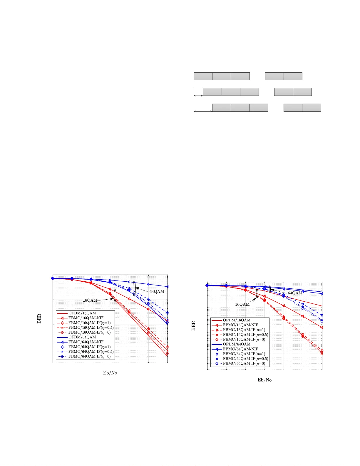
1 Comple x-V alued Symbol T ransmissions in Filter Bank Multicar rier Systems using Filter Decon v olution Adnan Zafar , Mahmoud Abdu llahi, Lei Z hang, Sohail T aheri, Pei Xiao and Muhamma d Ali Imran Abstract —T ransmission of complex-va lued symbols using fil- ter bank multicarrier systems has b een an issue du e to the self-interference b etween the t ransmitt ed symbols both in the time and frequency domain (so-called in trinsic i n terference). In th is p aper , we propose a nove l low-complexity interference- free filter bank multicarrier system wi t h QAM modulation (FBMC/QAM) using filter decon volution. The propose d method is b ased on inv ersion of the prototype filters which completely remo ves the intrinsic interference at the receiv er and allows the u se of complex-valued signaling. The interference terms in FBMC/QAM with and without th e proposed system ar e analyzed and compar ed in terms of mean square error (M S E). It is shown with theoretical and simulation results that th e proposed method cancels the in trinsic interference and impro ves the output signal to in terference p lus n oise ratio (SINR) at the expense of slight enhancement of residual interferences caused b y multip ath channel. The complexity of the pro posed system is also analyzed along with perfo rmance evaluation in an asynchronous multi- service scenario. It is shown that the proposed FBMC/QAM system with filter decon volution outperforms t he con ventional OFDM system. Index terms – FBMC, intrinsic interferen ce, interf erence analysis, filter deconv olution , inv erse filter I . I N T RO D U C T I O N I ncreasing demand s fo r hig her data rates in mob ile com muni- cation and 5 G application r e q uiremen ts su ch as Inter net o f Things (IoT), Gigabit wir eless connectivity , and tactile inter net present an ultimate challen ge to provide a unif orm service experience to users [1], [ 2]. T o this end, the new physical layer sho u ld provide two im portant featu res. First, variably ag - gregation of n on-adja c ent band s to acq uire higher bandwidths for data transmission [3]. Second , suppor tin g asynchrono us transmissions, re d ucing signalin g overhead and hand ling spo- radic traffic gener ating devices such as IoT d evices [ 4]. Th e features necessitate a n ew wa veform which provides very lo w out of ban d radiation (OoBR), as well as imm unity against synchro n ization errors. As orthog onal f r equency division multip lexing ( OFDM) is unable to satisfy the new physical layer requirem ents, se veral wa veforms have been introd uced as a p otential replac ement for it. Filter ba n k mu lticarrier with offset quad r ature amplitu d e A.Zafar , M.Abdullahi, S.T ahe ri and P .Xiao are with Institute for Communi- catio n Systems (ICS), Uni versit y of Surrey , Guildford, UK. Emails: { a.zaf ar , m.abdullahi , s.taheri, p.xiao } @surre y .ac.uk. A. Zafar is also affilia ted with Institut e of Space T echnology , Islamabad, Pakista n. L.Zhang and M.A.Imran are with School of Engineering , Uni versit y of Glasgo w , Glasgo w , UK. Email: { le i.zhang, muham- mad.imran } @gla sgow .ac.uk modulatio n (FBMC/OQAM) is one of the promising candi- dates which provide very low OoBR, as well as imm unity against syn chron ization errors, th anks to its per -subcar rier filtering [5]. The ma in drawback in FBMC/OQAM is that it relaxes the orthogo nality con dition to r eal field to utilize a well-localized filter in time and freq uency , an d m aintain trans- mission at the Nyquist rate [6]. Th is is becau se accor ding to Balian-Low th eorem [6]– [8], the r e is no way to utilize a well- localized p rototyp e filter in both time an d fre quency , a lo ng with maintaining orthog onality and transmitting at Nyqu ist rate. Thu s, relaxing th e orth ogon ality condition (OQAM mod- ulation) can g uarantee the o ther two factors. Consequ ently , the transmitted real symbols in this system are contaminate d with imagin ary interferen c e ter m s (intrinsic inter ference) at the receiver . The intrin sic interf erence is th e ma in issue for FBMC/OQAM tr ansceivers. First of all, in high ly disper si ve channels, th e system will not perfor m proper ly with single- tap eq ualization [ 9]. Second ly , m ultiple-inp ut-multiple- output (MIMO) a p plications su c h as m aximum likelihoo d detectio n [10], a nd th e Alamouti space-time block coding [1 1] are not directly applicab le to th e system. Finally , due to intrinsic interferen ce, chann el estimation process in FBMC/OQAM is not as straigh tforward as OFDM systems. T o facilitate ch annel estimation, it is nec e ssary for the tran sceiv er to perfo rm furth er pilot processing or waste part of the transmit resou rces [1 2], [13]. The idea behin d FBMC with QAM mod ulation is to reach a quasi-o r thogon al signal while maintainin g p e r-subcarrier filtering. Th ere ar e two ty pes of th is system in the literature. T ype I which was introduced in [14 ], uses two d ifferent prototy p e filters for odd and even subcarriers to mitig a te intrinsic interfer ence. One of th e pro posed filters in [ 14] suffers from very p o or OoBR which was enhan ced in [ 1 5] and [16]. T ype II of FBMC/QAM introdu ced in [15] uses an optimized prototy p e filter for all subcarriers. The adv antage of T ype II is that the OoBR rapidly decays to the desired level within on e subcarrier spacing, which is an imposed constraint on the cut- off frequen cy of the p rototyp e filter stated in [17]. This method is also k n own as filter b ank based OFDM (FB-OFDM) in [ 18]. Nev ertheless, the filter d e sig n in this typ e of system is q uite critical in order to achieve an acceptab le level of ortho gonality , while keep ing the N y quist proper ty in the time doma in . In this paper, we target at the filter design for type II of FBMC/QAM systems d ue to its mentioned advantage. T o mitigate the energy of intrin sic interfer ence in this system, a re- medial system is requir e d which is known as inver se system in 2 the gen e ral context of linear systems theory [19]. The inverse system, is cascaded with the m ulticarrier filtering , and th u s yields a replica of th e tr ansmitted symbo ls without interfere n ce terms, after channel equalization. Since the in verse system countera c ts the effect of multicarr ier filterin g, the process is called deco n volutio n . In this process, the transmitted symb o ls are separated fro m the filterin g characteristics of the system. W e pro pose this novel in ter ference- free FBMC system based on in version of the pro totype filters. T he advantage of this system is that it can retain the positiv e featur e s of FBMC and OFDM at the sam e time e.g . the channel estimatio n and equalization can be perf ormed in a straightforward way as in OFDM together with other advantages tha t can be achieved in FBMC systems, such as lo w OoBR and robustness to synchro n ization errors. The main contributions in th is work can be itemized as fo llows • A matrix mode l of the QAM ba sed FBMC system is presented in th e presence of additive no ise and multipath channel. Th e interf erence terms at the receiver d ue to channel distortions and th e intrinsic behavior of the transceiver model are also derived. • An inverse filter matrix b ased o n proto type filters is then introd uced at the receiver to cancel the effects of intrinsic inter f erence in th e FBMC/QAM system. It has been shown with theor e tica l analysis that the introdu ction of inverse filter completely rem oves the in trinsic inter fer- ence. • The inter ference terms inc lu ding th e on es introdu ced by the multipath channel are analyzed in terms of mean square error ( MSE) with and without the in verse filter . It is also shown that the interference can cellation p ro- cess significan tly improves the system outp u t signal to interferen ce plus noise ratio (SINR). • Complexity a nalysis of th e FBMC/QAM system with and without th e in verse filter is also presented. It is shown that the receiver complexity in both cases have the same up per bound s. The r est o f th is p aper is organized as follows. The system model of the FBMC/QAM system with an d with out interf er- ence cancellation, as well as the d eriv ation o f the interference terms are pr ovided in Sec. II. T he interfe r ence an d complexity analysis a r e p resented in Sec. I II and IV respectively . In Sec. V , the prop osed system is then ev aluated for an asynchro nous multi-service scenario an d th e perform ance is com p ared with conv ention a l OFDM system. Fina lly , th e con clusions a r e drawn in Sec. VI . Notations: V ec to rs an d m atrices are d enoted by lower - case and uppercase bold letters. {·} H , {·} T , {·} ∗ stand for the Hermitian con jugate, tra n spose and conjug ate opera tio n, respectively . E { A } de n otes the expectation operatio n of A . F an d F H represents the power nor malized N point discrete Fourier tr ansform (DFT) a n d in verse D FT (IDFT) matrices. I m × m refers to m dimensio n identity m atrix an d for some cases the sub scr ipt will be dr o pped for simplification whenever no ambiguity arises. k A k 2 n means taking the n th diagona l element of matrix k A k 2 = AA H . W e use ∗ as a linear conv olution oper ator . T r { A } d e notes the trace of matrix A . I I . F B M C / Q A M S Y S T E M In th is sectio n we define the FBMC/QAM sy stem in matrix form which will be sub sequently used to prop ose an inverse system based on proto type filters to cancel the ef fect of intrinsic interferen ce. A. System Model The system m odel is divided into tran smit p rocessing, multipath channel a nd receive processing blocks as follows 1) T ransmit Pr ocessing: The FBMC/QAM system f o llows a block ba sed p rocessing approach wher e ea ch block con - tains M FBMC/QAM symbo ls and each symb ol h as N subcarriers in the frequen cy domain i.e. each block is rep- resented a s S = [ s 0 , s 1 , · · · , s M − 1 ] ∈ C N × M where s m = [ s m, 0 , s m, 1 , · · · , s m,N − 1 ] T ∈ C N × 1 . Hen ce, the total num ber of QAM symbols transmitted in on e FBMC/QAM block is M N . Fur thermor e, the power o f the m odulated symbol s m,n is repr esented as δ 2 i.e., E {k s m,n k 2 } = δ 2 . Th e block diag ram for b o th transmitter an d receiver of FBMC/QAM is shown in Fig 1. Accord ing to Fig. 1, th e signal s m is passed thro ugh Channel Fig. 1 : Block diagram of FBMC/QAM system an N p oint IDFT p rocessor and can be expressed as b = [ b 0 ; b 1 ; · · · ; b M − 1 ] = [ F H s 0 ; F H s 1 ; · · · ; F H s M − 1 ] ∈ C M N × 1 . (1) 2) Pr oto type F ilter / F ilter Matrix: The signal th en passes throug h a prototyp e filter w . I t ha s been repor ted that a well- designed p rototyp e filter with moder a te leng th ( e.g., overlap- ping factor K = 4 ∼ 6) incurs negligible interference [20]. T o generalize our deriv ation, let us supp o se the filter overlapp ing factor is K , so the total length of the p rototyp e filter is K N i.e., w = [ w 0 , w 1 , · · · , w K − 1 ] = [ w 0 , w 0 , · · · , w K N − 1 ] ∈ R 1 × K N . I n general, the prototy pe filters are linearly conv olved with the input signal but to represent the com plete system in matrix form we hav e to present the filtering process in matrix form as well. The multiplication of th e filter matrix with the input vector is equiv alent to the required linear conv olution process. The prototy pe filter matr ix P ∈ R ( K + M − 1) N × M N is therefor e defined as P = W 0 0 0 · · · 0 W 1 W 0 0 · · · 0 . . . W 1 W 0 · · · 0 W K − 1 . . . W 1 · · · 0 0 W K − 1 . . . · · · W 0 0 0 W K − 1 · · · W 1 . . . . . . . . . . . . . . . 0 0 0 · · · W K − 1 , (2) 3 where W k = diag ( w k ) ∈ R N × N for k = 0 , 1 , 2 , · · · , K − 1 and w k = [ w kN , w kN +1 , · · · , w kN + N − 1 ] ∈ R 1 × N . T he output of the filter matrix P is form ed as o = Pb ∈ C ( K + M − 1) × 1 . (3) The outpu t of the filter i.e., o has ( K − 1) N mo re sam ples due to the linear conv olution pr ocess. 3) Channel Impu lse Response: W e assume the system operates over a slowly-varying fading channe l i.e., q uasi-static fading channel. I n such a scen ario, we can assume that the duration o f ea c h of the transmitted data b lock is smaller than the cohe r ence time o f the chann e l, th erefore th e rando m fading coefficients stay c o nstant over the du ration o f each b lock [21]. In this case, we d efine the m ultipath channel as a L -tap c h annel impulse resp onse (CIR) with th e l th -tap power being ρ 2 l . It is also assum e d th at the average power remain s constan t durin g the tr ansmission of the whole block. Let us define the CIR h as h = [ h 0 , h 1 , · · · , h L − 1 ] T = [ ρ 0 z 0 , ρ 1 z 1 , · · · , ρ L − 1 z L − 1 ] T , (4) where h l defines th e l th tap in the time d omain CIR and the complex ran dom variable z l with complex G a u ssian distribu- tion as C N (0 , 1) re p resents the m ultipath fading factor o f the l th tap o f the quasi-static rayleigh fading chann el. 4) P assing thr ough th e Chann el: Th e sig nal o after the prototy p e filtering is then passed throu gh the chann el h . The received signal is now represented as r = h ∗ o + n , (5) where n is Gaussian no ise with each elem ent having zero mean and variance σ 2 . T o r epresent the conv olution pr ocess giv en in (5) as matrix multiplication, we fir st defin e the l th tap multipath fading factor z l in a diagonal matrix form as follows: Z l = z l × I ( K + M − 1) N × ( K + M − 1) N . (6) The defin ition of Z l implies that each FBMC/QAM sy m bol in a block experiences the same channel. W ith all these definitions we can refor m (5) as r = L − 1 X l =0 ρ l Z l o ↓ l + o I B I + n , (7) where o I B I = P L − 1 l =0 ρ l Z l r B ,l is the inter-block interf er- ence (IBI) caused b y cha n nel multipath effect with r B ,l = [ r p,l ; 0 [( M + K − l ) N − l ] × 1 ] and r p,l ∈ C l × 1 is the interfering signal fro m the previous FBMC/QAM block. When guard time is lon ger than the ch annel dura tion, we h av e r B ,l = 0 and co nsequently , o I B I = 0 . In (7), o ↓ l represents l - sample delayed version o f o with z e ro paddin g in the fro nt and is represented as o ↓ l = [ 0 l × 1 ; o q,l ] . Where o q,l represents the first ( K + M − 1) N − l elements of o . From ( 3) we can write o ↓ l = P ↓ l b , where P ↓ l = [ 0 l × M N ; P q,l ] . Here P q,l is the first ( K + M − 1) N − l rows of P . W e can thu s refo r m ( 7) as follows: r = L − 1 X l =0 ρ l Z l P ↓ l b + o I B I + n . (8) Eq (8) in d icates that as a result of chann el m ultipath effect, the original P is rep la c ed by d isto r ted filter m atrix P ↓ l . In ord e r to demonstra te th e r elationship of the distor tion an d the multipath effect on the FBMC/QAM system, we first intro d uce a block diagona l exchanging matrix X l ∈ R M N × M N as follows: X l = X sub,l 0 · · · 0 0 X sub,l · · · 0 . . . . . . . . . . . . 0 0 · · · X sub,l ∈ R M N × M N , (9) with X sub,l = 0 l × ( N − l ) I l × l I ( N − l ) × ( N − l ) 0 ( N − l ) × l ∈ R N × N . (10) As X T l X l = I , we have o ↓ l = P ↓ l b = P ↓ l X T l X l b = P ↓ l e b ↓ l e . (11) The matr ix X T l and X l are used to exchang e the locations o f elements o f P ↓ l and b r e sp ectiv ely , such that P ↓ l e = P ↓ l X T l and b ↓ l e = X l b . By multiplying the matrix X l with b , the last l symbols of its each sub -vector b m will be moved to the front, i.e. b ↓ l e,m = [ b m,N − l · · · , b m,N − 1 , b m, 0 , · · · , b m,N − l − 1 ] T . (12) Like wise, ¯ b ↓ l e = [ b ↓ l e, 0 ; b ↓ l e, 1 ; · · · ; b ↓ l e,M − 1 ] ∈ C M N × 1 . (13) The effect is similar wh en m ultiplying X T l with P ↓ l . X T l only changes the elements locatio n in P ↓ l . Sub stituting (11) into (8) yields r = L − 1 X l =0 ρ l Z l P ↓ l e b ↓ l e + o I B I + n . (14) It can be observed that the non zero e lements of P ↓ l e and P a re very clo se i.e. the nonzer o elem ents of P ↓ l e are o nly delayed by l elements as comp ared to th e elem e n ts in P . If the no n -zero i th row and k th column element of P is w n , then the element of P ↓ l e at the same locatio n will b e w n + l . Since N ≫ L , the difference between w n and w n + l is very small as the adjacent e le m ents of the prototype filter are close to each oth e r . In or der to show the interferenc e caused by the multipath on the filter distortio n , we defin e P ↓ l e as follows: P ↓ l e = P + ∆ P ↓ l . (15) Eq (14) c an thus be written as r = L − 1 X l =0 ρ l Z l Pb ↓ l e + o f d + o I B I + n , (16) where o f d = P L − 1 l =0 ρ l Z l ∆ P ↓ l b ↓ l e is the inter ference caused by the filter distortion due to chann el multipath effect. 4 G = K − 1 X i =0 W i W i K − 1 X i =1 W i W i − 1 · · · K − 1 X i = K − 1 W i W i − K +1 0 · · · 0 K − 1 X i =1 W i − 1 W i K − 1 X i =0 W i W i · · · K − 1 X i = K − 2 W i W i − K +2 K − 1 X i = K − 1 W i W i − K +1 . . . 0 . . . . . . . . . . . . . . . . . . . . . K − 1 X i = K − 1 W i − K +1 W i K − 1 X i = K − 2 W i − K +2 W i · · · K − 1 X i =0 W i W i K − 1 X i =1 W i W i − 1 · · · 0 0 K − 1 X i = K − 1 W i − K +1 W i · · · K − 1 X i =1 W i − 1 W i K − 1 X i =0 W i W i · · · K − 1 X i = K − 1 W i − K +1 W i . . . . . . . . . . . . . . . . . . . . . 0 0 · · · 0 K − 1 X i = K − 1 W i − K +1 W i · · · K − 1 X i =0 W i W i (17) 5) Receive Pr ocessing: The received sign al r is first passed throug h th e recei ve filter bank, repre sented by th e matrix P H . The output of the receive filter b ank becom es x = P H r , = G L − 1 X l =0 ρ l Z l b ↓ l e + P H ( o f d + o I B I + n ) . (18) where G = P H P ∈ R M N × M N is th e autoco rrelation matr ix and has a stru cture as sh own in (17) with each elem ent being a diagon al sub -matrix of size N × N . W e will now analyze the FBMC/QAM system performance with and without an in verse filter at the receiver . B. Case 1: FBMC/QAM withou t inver se filter The FBMC/QAM system is affected b y in trinsic interfer- ence introdu ced by the transmit and receive filters. Th ese in ter- ference terms can significantly limit the system perf ormanc e. In this sub - section, we will derive these in terference term s to analyze their impact on the system perf ormance . 1) DFT Pr ocessing of the filter ed signa l: The signal vector at the outp ut of the receive filter matrix, i.e., P H is rep- resented as x = [ x 0 , x 1 , · · · , x M N − 1 ] T ∈ C M N × 1 and is then passed thr ough a serial to p arallel conv erter to split the vector into M segments each of which h as N elements to perfor m N - point DFT . The m th segment of the vector x is repr esents as x m = [ x mN , x mN +1 , · · · , ¯ x mN + N − 1 ] T ∈ C N × 1 for m ∈ 0 , 1 , · · · , M − 1 . T h e signal is now repre- sented as x = [ x 0 , x 1 , · · · , x M − 1 ] ∈ C N × M where x m = [ x m, 0 , x m, 1 , · · · , x m,N − 1 ] T ∈ C N × 1 . The signal vector after DFT is represented as follows y m = F x m ∈ C N × 1 , = F M − 1 X i =0 G m,i L − 1 X l =0 ρ l z l b ↓ l e,i + F P H m ( o f d + o I B I + n ) , (19) where G m,i is the m th row and i th column sub- matrices of G . W e can show that ch annel cir c ular con volution pr op- erty ho lds in (19) and that the channel coefficients an d the transmitted signal s i for i = 0 , 1 , ..., M can be written as point-wise m ultiplication for m in th e frequen cy dom a in. W e can write P L − 1 l =0 ρ l z l b ↓ l e,i = H cir b i in (19), wh ere the m atrix H cir = [ h ↓ l 0 , h ↓ l 1 , · · · , h ↓ l L − 1 ] being a N × N cir culant matrix. In gener a l, an N × N circulant matrix is fully defined b y its first N × 1 vector . In our case, H cir is deter mined by [ h 0 , h 1 , · · · , h L − 1 , 0 ( N − L ) × 1 ] T ∈ C N × 1 i.e., H cir = h 0 0 · · · 0 h L − 1 · · · h 1 . . . h 0 . . . . . . . . . . . . . . . h L − 2 . . . . . . . . . . . . 0 h L − 1 h L − 1 h L − 2 · · · h 0 0 · · · . . . 0 h L − 1 . . . . . . h 0 · · · 0 . . . . . . . . . . . . . . . . . . . . . 0 · · · · · · h L − 1 h L − 2 · · · h 0 , (20 ) Also by introdu cing F H F = I in (19), we obtain y m = F M − 1 X i =0 G m,i F H F H cir F H F b i + F P H m ( o f d + o I B I + n ) . (21) Using th e circu lar co n volution pro perty (p p.129 -130) [22], we can write F H cir F H = C , wher e C is the f requen cy domain channel coefficients in diago nal m atrix form and is given as C = diag [ C 0 , C 1 , · · · , C N − 1 ] ∈ C N × N . The n th block diagona l elem ent in the frequen cy re sp onse of th e c h annel can be repr esented as C n = P L − 1 l =0 h l e − j 2 π N nl , 0 ≤ n ≤ N . Also F ( b i ) denotes th e DFT pr o cessing of b i and accordin g to (1), we have F ( b i ) = s i , by substituting it into (21) we get y m = M − 1 X i =0 Q m,i Cs i + F P H m ( o f d + o I B I + n ) , ( 2 2) where Q m,i = F G m,i F H has th e following pro p erty Q m,i = I + ∆ Q m,m for i = m ∆ Q m,i for i 6 = m , (23) 5 Note that ∆ Q ∈ C M N × M N denotes the interference co - efficient matrix that d etermines the magnitud e o f intr insic interferen ce in th e received sign al block. Using (23), we can write (22) as follows y m = ( I + ∆ Q mm ) Cs m + M − 1 X i =0 ,i 6 = m ∆ Q m,i Cs i + F P H m ( o f d + o I B I + n ) , = Cs m + ∆ Q mm Cs m + M − 1 X i =0 ,i 6 = m ∆ Q m,i Cs i + F P H m ( o f d + o I B I + n ) . (24) 2) Channel Equalization: W e represent one tap channel equalizer as a diag onal matrix E and is applied to the signal y m as follows ˆ s m = Ey m , = ECs m + E ∆ Q mm Cs m + E M − 1 X i =0 ,i 6 = m ∆ Q m,i Cs i + E F P H m ( o f d + o I B I + n ) , (25) Let us now assume E to b e either ZF or MMSE i.e. the two most pop u lar linear channe l equ alizers. E = C H ( CC H + ν σ 2 /δ 2 I ) − 1 , (26) where ν = 0 for ZF wh ile ν = 1 is for M M SE. W e can now write (25) as ˆ s m = β s m + E ∆ Q mm Cs m + M − 1 X i =0 ,i 6 = m E ∆ Q m,i Cs i + E F P H m ( o f d + o I B I + n ) , (27) where β = EC is a diagon al m a trix with its n th diagona l element being defined as β n = E n C n = | E n | 2 | E n | 2 + ν σ 2 /δ 2 , (28) The estimated signal ˆ s m can now be expressed as follows ˆ s m = s m |{z} Desired Signal + ( I − β ) s m | {z } MMSE E s timation Bias + E ∆ Q mm Cs m | {z } ICI + M − 1 X i =0 ,i 6 = m E ∆ Q m,i Cs i | {z } ISI + E F P H m o f d | {z } Filter Dis tortion by Multipath + E F P H m o I B I | {z } IBI by Multipath + E F P H m n | {z } Noise . (29) Note that the estimatio n bias error ( I − β ) is an effect of compromising th e in terferen c e an d noise of the MMSE equalizer . Howe ver , ( I − β ) = 0 wh en the ZF recei ver is used. C. Case 2: FBMC/QAM with in verse filter W e can see from (29) that the transmitted signal s m is accompan ied b y ICI and ISI (in tr insic interfere n ce) terms along with interferences c aused by the multipath channel and the noise. W e can overcome the in trinsic in terferenc e by introd ucing an in verse filter matrix R at the rece i ver as shown in Fig. 2 . Let the inverse filter matrix be defin ed as Channel Fig. 2: Block diagram of FBMC/QAM system with In verse Filter the inv erse of th e auto correlatio n matrix G defined in (1 7) i.e. R = G − 1 ∈ R M N × M N . Since the auto correlation ma trix G is a b and diagonal matrix, the inverse of the band diagona l matrix will result in a spa r se matrix that con sists of diagona l sub-matrices as shown in Fig. 3. Th e sparse stru c tu re of the in verse filter can lead to a low co mplex d econv olution pro cess at the receiv er . It sho uld be no ted that each off diagon al sub- matrix in R has negligible middle N / 2 d iagonal elements represented as dotted section s in Fig. 3. An ar bitrary numb er of elements in the ran g e o f [0 , N / 2 ] can be r e placed h e re by zero to red u ce the co mplexity . Let the elemen ts of the dotted section considered in the comp lexity analysis be defined as η i.e. , if η = 0 , a ll N/ 2 diagonal ele m ents are con sidered, η = 0 . 5 represent N / 4 d iagonal elements in the range of [3 N / 8 , 5 N / 8] are considered , whereas η = 1 m eans none of the mid dle N / 2 diagona l elemen ts are con sidered in the co mplexity ana ly sis giv en in Sec. IV . . . . . . . . . . . . . . . . . . . . . . . . . . . . . . . . . . . . . . . . . . . N N N MN MN N/4 N/ 2 Fig. 3: Structure of inv erse filter m atrix R 6 Using (1 8), th e output of the in verse filter matrix R at th e receiver side ca n b e written as f ollows v m = M − 1 X i =0 U m,i L − 1 X l =0 ρ l z l b ↓ l e,i + R m P H m ( o f d + o I B I + n ) , (3 0) where R m ∈ C N × M N is the m th row of sub-matrices of matrix R , while U m,i = P M − 1 j =0 R m,j G j,i ∈ R N × N and has the following prop e r ty U m,i = I N × N for i = m 0 for i 6 = m , (31) Eq. (30) can now be written as f ollows v m = L − 1 X l =0 ρ l z l b ↓ l e,m + R m P H m ( o f d + o I B I + n ) . ( 32) 1) DFT Pr ocessing of th e filter ed signal: The signal after DFT processing is now represen ted as follows y m = Cs m + F R m P H m ( o f d + o I B I + n ) . (33) where Cs m = F P L − 1 l =0 ρ l z l b ↓ l e,m . 2) Channel Equalizatio n : The estimated symb o l ˆ s m after equalization can be expressed a s follows ˆ s m = Ey m , = β s m + E F R m P H m ( o f d + o I B I + n ) , (34) where β = EC is a diago nal matrix with its n th diagona l element rep resented as (2 8). The estimated signal ˆ s m can now be expressed as f ollows: ˆ s m = s m |{z} Desired Signal + ( I − β ) s m | {z } MMSE E s timation Bias + E F R m P H m o f d | {z } Filter Dis tortion by Multipath + E F R m P H m o I B I | {z } IBI by Multipath + E F R m P H m n | {z } Noise . (35) As we can see from (35) th at the transmitted signal s m is free from ICI and ISI terms as compared to the case with no in verse filter . Howe ver , the use of inverse filter matr ix R enhances the inter ferences caused by the multipath channel and no ise as shown in (35). There f ore, in what follows, we will in vestigate the interf erence an d noise power to analyze the usefuln ess of inv erse filter m atrix at the receiver . I I I . I N T E R F E R E N C E A N A L Y S I S Although the use of inverse filter matrix removes ISI and ICI, h owe ver , the interfer ence cau sed by the m ultipath ch annel and noise is en hanced due to the use of inverse filter matrix R . T herefor e we need to inv estigate the interf erence and no ise power enha n cement d ue to th e in verse filter at the r eceiver . This provide s d eep insigh ts and useful gu idelines for receiver design in the FBMC/QAM system. A. Interfer ence / no ise po wer in ca se of n o inver se fi lter As we can see from (2 9) that in c a se of n o inverse filter , the estimated symbo l is acc o mpanied with MM SE estimation bias, inte r ference terms like ICI, ISI, filter d istortion an d IBI due to multipath chann el and noise i.e., ˆ s m = s m |{z} Desired Signal + ψ r esd,m | {z } MMSE E s timation Bias + ψ I C I ,m | {z } ICI + ψ I S I ,m | {z } ISI + ψ f d,m | {z } Filter Dis tortion by Multipath + ψ I B I ,m | {z } IBI by Multipath + ψ noise,m | {z } Noise . (36) The MSE of the n -th mod ulation symb ol estima tio n in the m -th FBMC/QAM symbo l can be derived as γ tot,m,n = E || ˆ s m,n − s m,n || 2 = E k ψ r esd,m k 2 n + k ψ I C I ,m k 2 n + k ψ I S I ,m k 2 n + k ψ f d,m k 2 n + k ψ I B I ,m k 2 n + k ψ noise,m k 2 n . (3 7) 1) MSE of signal estimation bias: Th e desired signa l estimation bias is caused by the MMSE receiv er since it minimizes the MSE between the transmitted and recei ved signal. This leads to r esidual interferen ce in the estimated signal. Fr om ( 37) an d (2 9), we can write the variance of the signal estimation bias as γ r esd,m,n = E k ψ r esd,m k 2 n = E {k ( I − β ) s m k 2 n } = δ 2 ( I − β n ) 2 , (38) As E {k s m,n k 2 } = δ 2 and ac c ording to (28), β n = | C n | 2 | C n | 2 + ν σ 2 /δ 2 . Substituting β n in (38) yield s γ r esd,m,n = δ 2 ( I − β n ) 2 = δ 2 ( I − 2 β n + β 2 n ] , = δ 2 h I − 2 | C n | 2 | C n | 2 + ν σ 2 /δ 2 + | C n | 4 ( | C n | 2 + ν σ 2 /δ 2 ) 2 i , = δ 2 ν 2 σ 4 ( δ 2 | C n | 2 + ν σ 2 ) 2 . (39) Apparen tly , wh en the ZF receiver is adopted, γ r esd,m,n = 0 since ν = 0 . Howe ver , the Z F eq ualization leads to noise enhancem ent unlike MMSE r e c eiv ers. 2) MSE of ICI: W e can write the variance of the ICI from (37) and (29) as γ I C I ,m = E k ψ I C I ,m k 2 = E k E ∆ Q mm Cs m k 2 , = E [ E ∆ Q mm Cs m s H m C H ∆ Q H m,m E H ] , (40) As E {k s m,n k 2 } = δ 2 and fr om (2 3), we kn ow that ∆ Q m,m = Q m,m − I for i = m , we c a n thu s reform ulate the above equatio n as γ I C I ,m = δ 2 E ∆ { Q m,m − I } CC H ∆ { Q m,m − I } H E H , = δ 2 EQ m,m CC H Q H m,m E H − EQ m,m CC H E H − ECC H Q H m,m E H + ECC H E H , (41) T ak ing the n th diagona l element of (41), we have γ I C I ,m,n = δ 2 k EQ m,m CC H Q H m,m E H k n − k EQ m,m CC H E H k n − k ECC H Q H m,m E H k n + k ECC H E H k n , = δ 2 | E n | 2 | C n | 2 k Q m,m Q H m,m k n − | E n | 2 | C n | 2 k Q m,m k n − | E n | 2 | C n | 2 k Q H m,m k n + | E n | 2 | C n | 2 , = | E n | 2 | C n | 2 α I C I ,n . (42) 7 where α I C I ,n = k δ 2 Q m,m Q H m,m − Q m,m − Q H m,m + I N × N k n . 3) MSE of ISI: W e can write the variance o f the ISI f rom (37) and (29) as γ I S I ,m = E k ψ I S I ,m k 2 = E k M − 1 X i =0 ,i 6 = m E ∆ Q m,i Cs i k 2 , = E [ M − 1 X i =0 ,i 6 = m E ∆ Q m,i Cs i s H i C H ∆ Q H m,i E H ] , (43) As E {k s m,n k 2 } = δ 2 and from (23), we know that ∆ Q m,i = Q m,i for i 6 = m , we can thus wr ite the above equation as γ I S I ,m = δ 2 M − 1 X i =0 ,i 6 = m EQ m,i CC H Q H m,i E H , (4 4) T ak ing the n th diagona l element of (44), we obtain γ I S I ,m, n = δ 2 k M − 1 X i =0 ,i 6 = m EQ m,i CC H Q H m,i E H k n , = δ 2 | E n | 2 | C n | 2 α I S I ,n . (45) where α I S I ,n = k M − 1 X i =0 ,i 6 = m Q m,i Q H m,i k n . 4) MSE of Filter Distortion due to multipath channel: W e can write the variance of th e in terference cau sed by filter distortion due to multipath chann e l fro m (37) and (2 9) a s γ f d,m = E k ψ f d,m k 2 = E k E F P H m o f d k 2 , = E [ E F P H m o f d o H f d P m F H E H ] , = E F P H m E [ o f d o H f d ] P m F H E H , = E F P H m α f d P m F H E H , (46) Using (16), we can deter m ine α f d = E [ o f d o H f d ] as follows α f d = E hn L − 1 X l =0 ρ l Z l ∆ P ↓ l b ↓ l e o { L − 1 X l =0 ρ l Z l ∆ P ↓ l b ↓ l e o H i , = L − 1 X l =0 ρ 2 l E [ Z l ∆ P ↓ l b ↓ l e b ↓ lH e ∆ P ↓ lH Z H l ] , (47) From (4) and (6), E { Z l Z H l } = 1 sinc e z l ∈ C N (0 , 1) also we know that E { b ↓ l e b ↓ lH e } = δ 2 , consequ ently α f d = δ 2 L − 1 X l =0 ρ 2 l T r { ∆ P ↓ l ∆ P ↓ lH } , = δ 2 L − 1 X l =0 ρ 2 l T ↓ l , (48) where T ↓ l = Tr [∆ P ↓ l ∆ P ↓ lH ] . Sin ce T ↓ l is a scalar value, therefor e α f d is also a scalar value. Now substitutin g (48) into (46), yields γ f d,m = α f d E F P H m P m F H E H , (49) By taking the n th diagona l element of γ f d,m , we h ave γ f d,m,n = α f d k E F P H m P m F H E H k n , = α f d | E n | 2 . (50) where kF P H m P m F H k n = k I N × N k n . 5) MSE of IBI: Let u s consider the case when we have inter-block interfe r ence due to the lack of g uard time. W e can write the variance of the interferenc e caused by I BI from (37) and (29) as γ I B I ,m = E k ψ I B I ,m k 2 = E k E F P H m o I B I k 2 , = E [ E F P H m o I B I o H I B I P m F H E H ] , = E F P H m E [ o I B I o H I B I ] P m F H E H , = E F P H m α I B I P m F H E H , (51) where α I B I = E [ o I B I o H I B I ] , n ow using (7), we can determin e α I B I as α I B I = E hn L − 1 X l =0 ρ l Z l y B ,l on L − 1 X l =0 ρ l Z l y B ,l o H i , = E h L − 1 X l =0 ρ 2 l Z l E { y B ,l y H B ,l } Z H l i , (52) Since Z l has a complex Ga u ssian d istribution i.e. C N (0 , 1) and also Z l and y B ,l are u ncorrelate d , we can write th e above equation as follows α I B I = L − 1 X l =0 ρ 2 l E { y B ,l y H B ,l } , (53) E { y B ,l y H B ,l } is dep e ndent on the signal type of the last bock, where we assume it is also oc c upied by an FBMC symbo l with th e same power , then we have E { y B ,l y H B ,l } = E k P ( l ) b last k 2 = Tr P ( l ) E { b last b H last } P H ( l ) , = δ 2 T r P ( l ) P H ( l ) = δ 2 T r P cor r ( l ) ] , = δ 2 P cor r ( l ) , (54) where P ( l ) = [ P ( last − l ) ; 0 ( M + K − 1) N − l × M N ] in which P ( last − l ) contains th e last l -th rows o f P also b last is the symbol (after IDFT) in the last block and that E { b last b H last } = δ 2 I . Substituting (54) in (53), we o b tain α I B I = δ 2 L − 1 X l =0 ρ 2 l P cor r ( l ) , (55) Since P cor r ( l ) is a scalar value, th erefore α I B I is also a scala r value. Substituting it into (51), yields γ I B I ,m = α I B I E F P H m P m F H E H , (56) By taking the n th diagona l element of γ I B I ,m , we derive th e MSE due to IBI as γ I B I ,m,n = α I B I k E F P H m P m F H E H k n , = α I B I | E n | 2 . (57) where k F P H m P m F H k n = k I N × N k n . I f w e furthe r notice that the elements of P ( last − l ) are very small and co ntains the last l rows of matr ix W K − 1 . Th erefore , P cor r ( l ) will be a diag onal matrix with first l -th diag onal elements be- ing the square of the last l -th elements of filter w i.e., w 2 K N − l , w 2 K N − l +1 , ..., w 2 K N − 1 . W e can therefor e represent P cor r ( l ) as follows P cor r ( l ) = diag [ w 2 K N − l , w 2 K N − l +1 , ..., w 2 K N − 1 , 0 ( K + M − 1) N − l ] (58) 8 Using (58), we can have the following app r oximation γ I B I ,m,n ≈ δ 2 | E n | 2 L − 1 X l =0 ρ 2 l l − 1 X k =0 w 2 K N − 1 − k . (59 ) 6) MSE o f Noise: W e can write the variance of the noise from ( 37) and (29) as γ noise,m = E k ψ noise,m k 2 = E k E F P H m n k 2 , = E [ E F P H m nn H P m F H E H ] , = σ 2 E F P H m P m F H E H , (60) where E { nn H } = E k n k 2 = σ 2 since n is Ga ussian noise with each element having zero mean and variance σ 2 . T akin g the n th diagona l element o f (60), we have γ noise,m,n = σ 2 k E F P H m P m F H E H k n = σ 2 | E n | 2 . (6 1) where kF P H m P m F H k n = k I N × N k n . B. Interfer ence / no ise po wer in ca se of inver se filter As c an b e seen from (35) th at with the in verse filter , th e estimated symbol is accompan ied with MMSE estimation b ias, filter distor tion and IBI d u e to chann el m ultipath effect and noise i.e., ˆ s m = s m |{z} Desired Signal + ψ r esd,m | {z } MMSE E s timation Bias + ψ f d,m | {z } Filter Dis tortion by Multipath + ψ I B I ,m | {z } IBI by Multipath + ψ noise,m | {z } Noise . ( 62) Similar to ( 37), we can wr ite the MSE of the n -th mod u- lation symb ol estimation in the m -th FBMC/QAM symbol as follows γ tot,m,n = E || ˆ s m,n − s m,n || 2 = E k ψ r esd,m k 2 n + k ψ f d,m k 2 n + k ψ I B I ,m k 2 n + k ψ noise,m k 2 n . (63) 1) MSE of sign al estimation b ias: This residual in te r ference caused by the MMSE equalize r is same as ( 39) sin c e it is indepen d ent fro m the effect o f inv erse filter m atrix R . Hence, the interfer ence power of the MMSE estimatio n b iased is γ r esd,m,n = E k ψ r esd,m k 2 n = δ 2 ν 2 σ 4 ( δ 2 | C n | 2 + ν σ 2 ) 2 . (64) 2) MSE of F ilter Distortion due to multip ath channel: Fro m (63) and (35), the variance of interfer ence caused by filter distortion due to ch a n nel multipath effect in case of inverse filter is as γ f d,m = E k ψ f d,m k 2 = E k E F R m P H m o f d k 2 , = E [ E F R m P H m o f d o H f d P m R H m F H E H ] , = E F R m P H m E [ o f d o H f d ] P m R H m F H E H , = E F R m P H m α f d P m R H m F H E H , (65) From (48), we know α f d = E [ o f d o H f d ] = δ 2 L − 1 X l =0 ρ 2 l T ↓ l , ( 66) where T ↓ l = T r [∆ P ↓ l ∆ P ↓ lH ] . Sin ce T ↓ l is a scalar v alue, therefor e α f d is also a scalar value. Now substituting (66) into (65), yields γ f d,m = α f d E F R m P H m P m R H m F H E H , (67) By taking the n th diagona l element of γ f d,m , we obtain γ f d,m,n = α f d k E F R m P H m P m R H m F H E H k n , = α f d | E n | 2 ζ m,n . (68) where kF R m P H m P m R H m F H k n = ζ m,n k I N × N k n . 3) MSE of IBI: Let u s consider the case when we have inter-block interferen ce due to the lack of gu ard time. Fro m (63) and (3 5), we can write the variance of th e interfer e nce caused by IBI in case of inv erse filter as γ I B I ,m = E k ψ I B I ,m k 2 = E k E F R m P H m o I B I k 2 , = E [ E F R m P H m o I B I o H I B I P m R H m F H E H ] , = E F R m P H m E [ o I B I o H I B I ] P m R H m F H E H , = E F R m P H m α I B I P m R H m F H E H , (69 ) From (55), we already know α I B I = δ 2 L − 1 X l =0 ρ 2 l P cor r ( l ) , (70) Since P cor r ( l ) is a scalar value, th erefore α I B I is also a scala r value. Substituting (70) into (69), yield s γ I B I ,m = α I B I E F R m P H m P m R H m F H E H , ( 7 1) By taking the n th diagona l element of γ I B I ,m , we derive th e MSE of IBI as γ I B I ,m,n = α I B I k E F R m P H m P m R H m F H E H k n , = α I B I | E n | 2 ζ m,n . (72) where kF R m P H m P m R H m F H k n = ζ m,n k I N × N k n . 4) MSE of Noise: From (63) and (35), the variance of no ise in ca se o f inv erse filter as γ noise,m = E k ψ noise,m k 2 = E k E F R m P H m n k 2 , = E [ E F R m P H m nn H P m R H m F H E H ] , (73 ) As E { nn H } = E k n k 2 = σ 2 since n is Gaussian noise with each element h aving ze ro mean and variance σ 2 . T aking the n th diagona l element of (73), we obtain γ noise,m,n = σ 2 k E F R m P H m P m R H m F H E H k n , = σ 2 | E n | 2 ζ m,n . (74) where kF R m P H m P m R H m F H k n = ζ m,n k I N × N k n . Note that the ζ m,n is th e noise / interferen ce en hanceme n t factor which is introdu ced wh en we use an inverse filter m atrix at the receiver . The noise/interf erence enhancement factor per subcarrier pe r sym bol ( ζ m,n / subcarrier / sy m bol) is presen ted in Fig. 4. I t can be seen that the noise en hancem e nt factor is constant fo r every sub carrier in each symbol and its effect is maximum for the symb ols in the m id dle of the FBMC/QAM data block as shown in Fig. 4a. Howev er, the impact is not significant since the av erage enh ancemen t factor in a bloc k is 1.32 as can be seen fro m Fig. 4b. 9 0 5 10 15 0 10 20 30 40 50 60 1.15 1.2 1.25 1.3 1.35 1.4 (a) ζ m,n / subcarrier / symbol 0 5 10 15 1.1 1.15 1.2 1.25 1.3 1.35 1.4 1.45 1.15 1.2 1.25 1.3 1.35 1.4 (b) ζ m,n / symbol Fig. 4: Noise/In terferen ce enhan cement factor ζ m,n for N = 64 and M = 14 I V . C O M P L E X I T Y A N A LYS I S In this section we have pr esented the c o mplexity analysis of the FBMC/QAM system with and without in verse filter at the receiver . The objective is to deter mine if ther e is a significan t increase in the complexity of the system with th e intro duction of the in verse filter matrix at th e receiver . T ypically th e complexity of a system is me asured by the nu mber of floating point opera tio ns ( FLOPS), we howe ver , only focu s on the number o f real mu ltip lications in our comp lexity analysis. Since we hav e already presented the FBMC/QAM transmitter and receiver processes in matrix multiplication for m in Section II, w e hav e a dopted the naive matrix multiplicatio n algo rithm [23] to perfo rm the comp lexity analysis. A. Comple xity ana lysis in case of no invers e filter T o determ ine the complexity of the FBMC/QAM system without in verse filter , we hav e to lo ok at th e structure of the system as shown in Fig. 1. 1) T ransmitter Complexity: Since our mo del follows a block based processing app roach, the inp ut to th e system is a vector o f size M N . Each QAM symb ol in the FBMC/QAM transmitter requ ir es an N -point IDFT op eration. The most effi- cient FFT algor ithm i.e. split-r adix require s N log 2 N − 3 N + 4 real m ultiplications [24], [ 25]. T he comp lex vector b at the output of the IDFT processor is then pro cessed throu gh the transmit filter matrix P . Since, the structure of P is sparse as shown in (2), the numbe r of real multip lica tio ns inv olved in filtering operatio n is determ ined as P M N k =1 P k b k = 2 M N K per blo ck. Where P k is the numbe r of n onzero elements in the k th column of matrix P , and b k is th e number of nonzero elements in the k th row of vector b . The total number of real multiplications inv olved in the tran sm itter per complex-valued symbol is C Tx = N l og 2 N + (2 K − 3) N + 4 . (7 5) 2) Receiver Complexity: I t can be seen from Fig. 1, the transmitted sign al o , afte r passing th rough the ch an- nel, is receiv ed by the recei ver as a complex vector r and is pro cessed by the receiver filter . Using the naive matrix multiplicatio n algo rithm , the number o f real multiplications in volved in this stage is 2 M N K p er block. Af- ter serial to parallel co nversion, each symb ol is processed by a 256 512 1024 2048 0 2 4 6 8 10 12 10 4 Fig. 5: Complexity compar ison of FBMC/QAM with and without in verse filter fo r K = 5 an d M = 14 N p oint DFT op eration resulting in N l og 2 N − 3 N + 4 real mu l- tiplications for processing one sym bol. The com plex-valued symbols after the D FT processing are th e n equalized using E as defined in (2 6). The eq ualization process requ ires 4 M N real m u ltiplications to estimate o ne tr ansmitted FBMC/QAM block. Hence, the total number of real multiplicatio ns per complex symbol in the case o f no in verse filter ( NIF ) a t the receiver is C N I F Rx = N l og 2 N + (2 K + 1) N + 4 . (76) B. Comple xity a nalysis in case of in verse filter The transmitter complexity in this case is the same as (75) since inverse filter only in c reases the co mplexity of the receiver . Th e total num ber of real m ultiplications pe r sym b ol in ca se o f inv erse filter ( I F ) at the receiv er is C I F Rx = C N I F Rx + C R . (77) where C R = 2 M N − η N ( M − 1) is the n umber of addition al real multiplicatio ns per sym bol introdu ced by the inverse filter and depend s on the value o f η as d efined in Sec. II-C. It can be seen fr o m (7 7) that the complexity of the receiv er with in verse filter ( C I F Rx ) d e pends o n the b lock size ( M ). Hence, the addition al complexity will be higher for large block size. The complexity in term s of r eal multiplications per sy mbol with an d withou t the in verse filter is pr esented in Fig. 5. I t is worth mentio n ing that the worst case o r the upp er bound o f the receiver comp lexity i.e., Big– O is O ( N l og 2 N ) 1 for both cases an d can be d etermined b y dropp ing the lower order terms and the constant multipliers in (76) and (77). V . S I M U L A T I O N R E S U LT S In this section we pr esent th e simulation results for MSE and ou tput SINR of the FBMC/QAM system with and witho ut 1 Although matrix inv ersion has a general complexity of O ( N 3 ) which can significantl y increase the complexity of the recei ver . Ho wev er , since the coef ficient s in the autocorrela tion matrix G are constant, we can calculat e the in ve rse filt er matri x R = G − 1 ∈ R M N × M N of f-line. 10 10 20 30 40 50 60 70 80 -160 -140 -120 -100 -80 -60 -40 -20 0 (a) Indi vidual MSE 10 20 30 40 50 60 70 80 -11.5 -11 -10.5 -10 -9.5 -9 -8.5 -8 -7.5 -7 (b) Composite MSE 10 20 30 40 50 60 70 80 7.5 8 8.5 9 9.5 10 10.5 11 11.5 (c) SNR Vs SINR Fig. 6: Perform a n ce of FBMC/QAM without Inverse Filter 10 20 30 40 50 60 70 80 -350 -300 -250 -200 -150 -100 -50 0 (a) Indi vidual MSE Componen ts 10 20 30 40 50 60 70 80 -35 -30 -25 -20 -15 -10 -5 (b) Composite MSE 10 20 30 40 50 60 70 80 5 10 15 20 25 30 35 (c) SNR Vs SINR Fig. 7: Perform a n ce of FBMC/QAM with Inverse Filter in verse filter along with the BER performan ce in case of synchro n ous and asynch ronou s m ulti-service scen arios. A. MSE and ou tput SI NR The per forman ce in term s of MSE and ou tput SINR in a FBMC/QAM system without and with the in verse filter at the receiver can be observed from Fig. 6 and Fig. 7 r espectively . The in dividual MSE sources like noise, r esidue f rom the equalization , IBI, ISI, ICI and filter d istortion in the two cases are shown in Fig. 6 a and Fig. 7 a respe ctiv ely . It can be seen that with o ut inv erse filter , the contribution of ICI and ISI (intrinsic inte r ference) is qu ite significant i.e. ar ound -1 6.5dB and -13 dB r espectiv ely . Howe ver , with th e use of inverse filter the intrinsic inte r ference beco mes n egligib le i.e. , ISI is around -310d B and ICI cann o t be even displayed on the same scale. The interference cau sed by the multip ath effect includ es filter distor tio n and IBI which c o ntributes around -3 2.5dB and -45dB respecti vely in case of no in verse filter . Howe ver , th e se values incr e a se to around -31.5d B and -43 .5dB respe c ti vely with th e use of in verse filter . T he increase in interference is due to th e enhanc e m ent factor ζ m,n introdu c ed by the use of in verse filter matr ix at the receiver as discussed in Sec. III-B. The overall MSE per forman ce of FBMC/QAM system without and with the in verse filter are shown in Fig . 6b and Fig. 7b r espectively . It can be observed that withou t th e in verse filter , the system beco mes interference limited beyond SNR=30dB and the MSE is arou nd -11. 2 dB. Howe ver , the use of inverse filter improves the system p erform ance and these values b e come 50dB and -31dB respectively . T he output SINR of the system also im p roves with the use of in verse filter as can be seen from the Fig. 6c and Fig. 7c. It can also be con firmed that th e in te r ference terms in the system model give in (29) and (35) com pletely matches with th e simulation results, wh ich verifies the acc u racy of the derived analytical model. 10 20 30 40 50 60 70 80 -80 -70 -60 -50 -40 -30 -20 -10 0 Fig. 8 : Noise & Interfer ence Enhan cement The noise and interfe r ence ( γ I B I and γ f d ) enhancem e nt due to the use of inverse filter ( IF ) is illustrated in Fig. 8. It can be seen th at the enhan cement is very small co mpared to the no inverse filter case ( NIF ) . The inter ference enh ancement is therefor e negligib le in co mparison to the level o f perfo rmance 11 improvement achieved with th e u se of in verse filter . B. BER P erformance The coded results (conv olution al co de with code rate 1/2 and generator polyno mials d efined as [133, 1 71]) for the BER perfor mance o f FBMC/QAM system with and without inverse filter are presented for synchron ous and asynchron ous multi- user tr ansmissions. W e have considered a mu lti-user (mu lti- service) tra n smission scenario sinc e next generation wireless systems are expe c te d to provide a fle xible framework fo r heteroge n eous serv ices. In such a case, services like mobile broadb and (MBB), Internet of th ings (IoT), u ltra reliable commun ication (URC) may coexist in adjace n t sub-bands. T o evaluate the perform a nce of FBMC/QAM system w ith multi-service tr ansmission, we segregate the whole b andwidth into three consecutive sub-bands, each for different user (ser- vices). The BER perform ance of the FBMC/QAM system with and withou t inverse filtering fo r syn chrono us segregated spectrum is shown in Fig. 9 . W e ha ve used conventional OFDM as a b a seline scheme to compar e the per forman ce of the FBMC/QAM system with and without in verse filter . For a fair compar ison between the two systems, the SNR loss, du e to the cyclic prefix (overhead) in OFDM, mu st be considered . For this reason , we have calcu lated the noise power for bo th systems as discussed in [2 6]. It can be seen from Fig. 9 that with out in verse filter (FBMC/QAM-NIF), the FBMC/QAM system has po o r perfor mance compared to co n ventional OFDM system due to the pr esence of in- trinsic interference . Since, FBMC/QAM with in verse filter (FBMC/QAM-IF) can cancel th e intrinsic in terference at the receiver , the system can p rovide comp arable p e rforman ce to the conventional OFDM system as shown in Fig. 9. 4 6 8 10 12 14 16 10 -6 10 -4 10 -2 10 0 Fig. 9: BER performanc e of OFDM and FBMC/QAM system with synchr onous sub-ban ds Howe ver , it is likely th a t the adjacent sub -band s in a multi-service transmission are out of syn c since simple IoT devices in future wireless n etworks may only hav e coarse synchro n ization. Thus it is very desirable fo r the system to be robust ag ainst asynchron ism betwee n adjacent sub-b ands. T o ev aluate the perfo rmance of FBMC/QAM und e r a synchro n ous sub-ban d s, we hav e considered the tim ing offset between two adjacent sub-b a nd transmissions to be 5 0 % of the sym b ol interval as shown in Fig 10. Since the second su b-band . . . . . . . . . User 1 User 2 User 3 T/2 T Symbol 1 Symbol 2 Symbol 3 Symbol M-1 Symbol M Fig. 10: Asynchr onou s user streams transmission suffers interfer ence fr o m the first and third sub- band, it is ap prop r iate to inv estigate the BER performa nce of the second sub -band user . In case of mu lti-service asyn- chrono us tra nsmission, the BER perf o rmance of FBMC/QAM with an d without inverse filter is shown in Fig. 11. It can be seen that in case of asyn c h rono u s multi-serv ice transmission, FBMC/QAM with inverse filter significantly o utperf o rms the the co n ventional OFDM system. W e can a lso observe the impact of neglecting the diag o nal elements in matrix R on the system BER per f ormanc e. It can be seen f rom Fig. 9 and Fig. 11 that for η = 0 the BER pe rforma n ce is better than η = 1 sin c e we are u sing all th e diagona l elements in the inverse filter matrix. Howe ver , the complexity of system is lower for η = 1 as neglecting midd le N / 2 ele m ents in the off-diago nal sub- matrices of R leads to less addition al real multiplications. It is th erefore a trade-off between the complexity a nd the system BER perfor mance i.e., a hig h er value of η leads to lower co mplexity as well as worse BER perfor m ance. Whereas a lo wer value o f η lea d s to higher complexity as well as be tter BER perf ormanc e. In 4 6 8 10 12 14 16 10 -6 10 -4 10 -2 10 0 Fig. 11: BER perfor mance of OFDM and FBMC/QAM system with asy nchron ous sub-ban ds the light of a ll the results, the improved perfor m ance of FBMC/QAM comp a red to co n ventional OFDM systems alo n g with its go od o ut-of-b and leakage p erforma nce, robustness to asynchro nous mu lti-service transmissions and ab ility to have 12 flexible sched u ling on subcarrier level makes it a suitable candidate for next generation wireless applications, e sp ecially for massiv e machine type commun ications. V I . C O N C L U S I O N W e ha ve proposed a novel low-complexity interferenc e - free FBMC/QAM system based on matrix inversion of th e prototy p e filter s that mitigates the intrinsic interferen ce in a FBMC/QAM system. The proposed system enables the use of complex-valued symbol tran smission, while maintaining per subcarrier based filtering. T he propo sed system is based on a compact matrix mo del of the FBMC/QAM system, which also laid the g r ound for a n in-depth analysis of the interfe rences affecting the system when oper ating in a m ultipath environ- ment. T he inter ference term s due to channel distor tions and the intrinsic beh avior o f the tran scei ver mo del h av e been de riv ed in d etail and ana ly zed in term s of MSE with and without the in verse filter . It was shown throu g h the the oretical and simulation results that inverse filtering significantly redu ces the in terference in FBMC/QAM system at the expense of slight enh ancement in IBI, interfe rence due to filter disto r- tion caused b y multip ath channel and n oise. The co m plexity analysis of the system with and without the in verse filter is also provided which shows that complexity in both cases have the same u pper bou nds. Th e perform ance of the sy stem is then evaluated for synchro nous and asynch ronou s multi- service scenarios. Sim u lation re sult shows that FBMC/QAM with in verse filter ca n p rovide comparable performanc e to the conv ention a l OFDM system in case of synchr onou s mu lti- service transmission while it ou tperfor ms OFDM in the asyn - chrono us c ase. The improved per forman ce of the prop osed FBMC/QAM system makes it high ly su itable for n ext gen- eration wireless app lications, especially for m a ssi ve m achine type commu n ications. R E F E R E N C E S [1] G. Wunde r , P . Jung, M. Kasparic k, T . Wil d, F . Schaich, Y . Che n, S. T . Brink, I. Gaspar , N. Michai low , A. Festag, L. Mendes, N. Cassiau, D. Kten as, M. Dryjanski, S. Piet rzyk, B. Eged, P . V ago, and F . W ied- mann, “5gno w: non-orth ogonal, asynchronous wav eforms for future mobile appl ication s, ” IEEE Communic ations Magazine , vol. 52, no. 2, pp. 97–105, February 2014. [2] L. Zhang, A. Ijaz , P . Xiao, A. Quddus, and R. T af azolli, “Subba nd fil- tered multi-carrier s ystems for multi-servic e wirele ss communica tions, ” IEEE T ransactio ns on W ir eless Communication s , vol. 16, no. 3, pp. 1893–1907, March 2017. [3] H. Bogucka, P . Kryszkiewi cz, and A. Kliks, “Dynamic spectrum aggre- gation for future 5g communica tions, ” IEEE Communi cations Magazine , vol. 53, no. 5, pp. 35–43, May 2015. [4] D. Ma ttera, M. T anda, and M. B ellanger , “ Analysi s of an FBMC/OQAM scheme for asynchronou s access in wireless communic ations, ” E URASIP J ournal on Advances in Signal Pr ocessin g , vol . 2015, no. 1, pp. 1–22, 2015. [5] Y . Y uan and X. Zhao, “ 5G: V ision , scenari os and enabling te chnologie s, ” ZTE Communicati ons , vol. 13, no. 1, pp. 3–10, Mar ch 2015. [6] A. Sa hin, I. Guven c, and H. Arslan, “ A survey o n multicarri er communi- catio ns: Prototype filters, lat tice structures, and implementa tion aspects, ” Communicat ions Survey s T utorials, IEEE , v ol. 16, no. 3, pp. 1312–13 38, March 2014. [7] I. Daubechie s, “The wa velet transform, time-frequ ency localizat ion and signal analysis, ” IEEE T ransact ions on Information Theory , vol. 36, no. 5, pp. 961–1005, Sep 1990. [8] J. J. Benedetto, C. Heil, and D. F . W alnut, “Dif ferentia tion and the Balia n-Low theorem, ” Journal of F ourier Analysis and Applications , vol. 1, pp. 355–402, 1995. [9] L. Zhang, P . Xiao, A. Zafar , A. Quddus, and R. T afazolli , “FBMC system: An insight analysis on double dispersi ve channel impact, ” IEEE T ran sactions on V ehicul ar T ech nology , vol. 66, no. 5, pp. 3942–3956, May 2017. [10] R. Zakaria and D. Le Ruye t, “On spatial data multi plexi ng ove r coded filter-bank multicarrier with ML detecti on, ” P erson al Indoor and Mobile Radio Communications (PIMRC), 2011 IEEE 22nd Interna tional Symposium on , pp. 1391–1395, Sept 2011. [11] C. L ´ el ´ e, P . Siohan, and R. Legouable , “The Alamouti scheme with CDMA-OFDM/OQAM, ” EURASIP J ournal on Advanc es in Signal Pr ocessing , vol. 2010, pp. 2:1–2:11, Jan. 2010. [12] S . T aheri, M. Ghoraishi, P . Xiao, and L . Z hang, “Effici ent implementa- tion of filter ban k m ultic arrier syste ms using circular fast con volut ion, ” IEEE Access , vol. 5, pp. 2855–2869, 2017. [13] S . T aheri, M. Ghorai shi, P . Xiao, A. Cao, and Y . Gao, “Eval uation of preamble based channe l estimatio n for MIMO-FBMC systems, ” ZTE Communicat ions , vol . 14, no. 4, pp. 3–10, Oct 2016. [14] H. Nam, M. Choi, C. Kim, D. Hong, and S. Choi, “ A ne w filter -bank multica rrier system for QAM signa l transmission an d recept ion, ” 2014 IEEE Internati onal Confer ence on Communications (ICC) , pp. 5227– 5232, June 2014. [15] Y . H. Y un, C. Kim, K. Kim, Z. Ho, B. Lee, and J. Y . Seol, “ A ne w wav eform enabling enhanced QAM-FBMC systems, ” 2015 IE EE 16th Internation al W orkshop on Signal Proce ssing A dvances in W ir eless Communicat ions (SP A WC) , pp. 116–120, June 2015. [16] C. Kim, K. Kim, Y . H. Y un, Z . Ho, B. Lee, and J. Y . Seol , “QAM-FBMC : A ne w multi-carrier syste m for post-OFDM wireless communications, ” 2015 IEE E Global Communications Confer ence (GLOB ECOM) , pp. 1– 6, Dec 2015. [17] M. G. Bellanger , “Speci fication and design of a prototy pe filter for filter bank based multicar rier transmission, ” 2001 IEE E Internatio nal Confer ence on Acoustics, Speech, and Signal P r ocessing . Pr oceedings (Cat. No.01CH37221) , vol. 4, pp. 2417–2420 v ol.4, 2001. [18] X. Y u, Y . Guanghui, Y . Xiao, Y . Zhen, X. Jun, and G. Bo, “FB-OFDM: A novel multicarri er scheme for 5G, ” 2016 Europe an Confer ence on Network s and Communicat ions (EuCNC) , pp. 271–276, June 2016. [19] J . G. Proakis and D. K. Manola kis, Digital Signal Pr ocessing (4th Edition) . Upper Saddle Riv er , NJ, USA: Prentice-Hal l, Inc., 2006 . [20] M. Sche llmann, Z. Zhao, H. Lin, P . Siohan, N. Ra jathe v a, V . L ueck en, and A. Ishaque, “FBMC-based ai r interface for 5G mobile: Challenges and proposed solutions, ” 9th International Confer ence on Cogni tive R a- dio Oriented W ir eless Networks and Communication s (CRO WNCOM) , pp. 102–107, June 2014. [21] D. T se and P . V iswa nath, Fundamentals of wirel ess communication . Cambridge uni versit y press, 2005. [22] S . Sesia, LTE - the UMTS long term evolution : fr om theory to practi ce . Chiche ster: W ile y , 2011. [23] R. Y uster and U. Zw ick, “Fast s parse matrix multiplic ation, ” A CM T ran sactions on A lgorithms (T ALG) , vol. 1, no. 1, pp. 2–13, 2005. [24] R. Gerzaguet, N. Bartzoudis, L. G. Baltar , V . Berg, J.-B. Dor ´ e , D. Kt ´ e nas, O. Font-Bach, X. Mest re, M. Payar ´ o, M. F ¨ arber , and K. Roth, “ The 5G candi date wav eform race: a co mparison of comple xity and performance, ” EURASIP Journal on W ire less Communication s and Network ing , vol. 2017, no. 1, p. 13, J an 2017. [Online]. A vaila ble: https:/ /doi.org/1 0.1186/s13638- 016- 0792- 0 [25] L . Zhang, A. Ijaz, P . Xiao, and R. T af azolli , “Multi -service system: An enable r of flexi ble 5g air interf ace, ” IEEE Communic ations Magazine , vol. 55, no. 10, pp. 152–159, OCTOBER 2017. [26] A. Zafar , M. A. Imran, P . Xia o, A. Cao, and Y . Gao, “Performance e v alu- ation and comparison of dif ferent m ultica rrier modulati on schemes, ” in Computer Aided Modelling and Design of Communicat ion Links and Network s (CAMAD), 2015 IEEE 20th Int ernational W orkshop on , Sept 2015, pp. 49–53.
Original Paper
Loading high-quality paper...
Comments & Academic Discussion
Loading comments...
Leave a Comment