Nobody but You: Sensor Selection for Voltage Regulation in Smart Grid
The increasing availability of distributed energy resources (DERs) and sensors in smart grid, as well as overlaying communication network, provides substantial potential benefits for improving the power system's reliability. In this paper, the proble…
Authors: Rukun Mao, Husheng Li
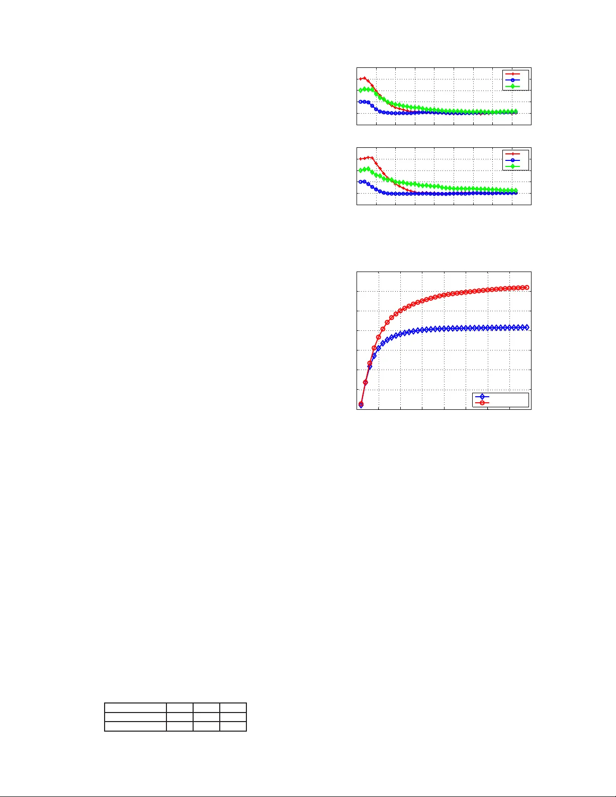
Nobody But Y ou: Sensor Selecti on for V olta ge Re gulation in Smart Grid Rukun Mao and Hushe ng Li Departmen t of Electrical Eng ineering and Computer Scienc e The University of T ennessee at Knox ville Email: { rmao,h usheng } @eecs.u tk.edu Abstract —The increasing a vailability of distributed e nergy resour ces (DE Rs) and sensors i n smart grid, as well as overlay ing communication network, prov ides su bstantial potential benefits fo r imp ro ving the power system’s reliability . In this paper , the problem of sensor selection is stu died f or the MA C layer design of wireless sen sor networks f or regulating t he voltages in smart grid. The framework of hybrid dynamical system is proposed, using Kalman fi lter f or voltage state estimation and LQR feedb ack control fo r voltage adjustment . The approach to obtain the optimal sensor selection sequence is stud ied. A sub- optimal sequence is obtained by applying the sliding wi ndo w algorithm . Simulation results show that the proposed sensor selection strategy achieves a 40% performance gain over t he baseline algorithm of t he round-robin sensor polli ng. I . I N T RO D U C T I O N A N D M OT I V A T I O N Ordinary electric al grids in many cou ntries ar e undergoin g a rev olutionary chan ge of ev olving to smart grid s, which are characterized b y a tw o-way flow of e lectricity and informa tion and will be capable of monitorin g everything in the grid [ 2]. By bringing in a variety o f Distrib uted Energy Resources (DERs), in particular renewable sources such as solar pan els and wind turb ines, smar t g rid addresses both globe warming and emergency resilience issues. In this p aper we stud y the wir eless commu nication pr o tocol design for r e gulating the vo ltages in smart grid which has a shar ed co mmunication channe l a mong co ntr ol center , vo ltage sensors and DERs . Th e feasibility of DE R for regulatin g voltage has bee n well re ported in the literature, such as [6] . As shown in Fig. 1, m ultiple sen sors monitor the voltage states at { V a , V b , . . . } and report the states to the v oltage control center . Based on all rec ei ved rep orts, the control center estimates the voltage states. If the estimate d voltage state is d e viated from a preset desired value, the control center coordinates all a v ailable DERs to regulate voltage. Th e arrival of ne w repor t from sensor trig gers the c ontrol c enter to perfor m an other rou nd of voltage state estimation and regulatin g. T he above iter ati ve voltage regu lating proce ss con tinues un til th e th e voltages ar e within a desired rang e. The motiv ation of ou r work is the in creasing a vailability of DERs, voltage sensors, and the overlayin g communic ation network in p ower networks [1]. Although the voltage regu- lation for power system stability h as been a critical problem under intensive study [ 4]–[7] , the new pro perties an d p otential benefits brought by these new facilities still need more ef fort to uncover . T ake the micr ogrid as an examp le [3], in which DERs Fig. 1: Distrib uted Energy Resources for V olta ge Control have demon strated their abilities of increasing p ower qu ality and reliab ility in pr actical systems; howev er , developing alter- native control strategies using next-g eneration information and commun ication technolo gy is still an open q uestion. Existing solutions for the voltage contr ol p roblem with DERs eithe r focus on an alyzing th e p ower system model or m ainly stu dy control method design, e.g., the Model Predic ti ve Contr ol (MPC) [ 4], [5] or PID contro ller [6], [7]. W e will f ocus on the MAC layer design of the wir eless sensor networks for the voltage r e gulation . When orthog onal commun ications are requir ed, i.e., on ly one tran smitter ca n access the c hannel at the same time a nd collisions in cur packet loss 1 , it is o f key imp ortance to stud y the p roblem of sensor selection. A simple solution is to use rou nd-ro bin sch eduling, i.e., the sensors take regular turns to report their measurements, regardless of the cu rrent voltage states. Howe ver , as will be seen later , a s ignificant perfo rmance gain over the simp le scheme will be achieved by manipu lating the senso rs in a system state aware mann er . Particularly , we will m odel the power grid as a hybr id system [8] [1 1], in which the power system is th e c ontinuou s subsystem while the comm unication system is the discrete sub system. The sensor selectio n will be co nsidered as th e switching of the system dynamics mode. Then, we apply a sliding win dow algorith m to optimiz e the sensor s election, or equi v alently , the system mode selection. T o our best knowledge, the re hav e not been any stud ies ap plying the hybrid system theory to the communication protoc ol design 1 It is straight forward to ext end to the case that multiple sensors can be schedule d simultaneously in smart grid. The remainder of the paper is organized as follo ws. In Section II, we in troduce the modelin g of p ower system with sensors reportin g th rough a shar ed comm unication channe l, as well as the form ulation o f the voltage co ntrol problem . In Section III, we describ e th e voltage co ntrol procedu res and the algor ithm for o ptimizing the sen sor selection in the MAC layer . An example application and its simulation results will be reported in Section IV. Th e con clusions are given in Section V. I I . S Y S T E M M O D E L A N D P RO B L E M F O R M U L AT I O N In th is section, we first introduce the system mo del, includ - ing th e power dyn amics, system co st an d commu nication sys- tem. Then, we for mulate the pro blem as three sub- problem s. A. P ower System Dyn amics W e use th e f ollowing d ifferential-algebraic equa tion (DAE) to describe our target p ower system, which is given b y ˙ x = f ( x , u , w ′ ) , w ′ ∼ N ( 0 , Q ′ ) , (1) where x ∈ R n is the system state r epresenting the voltages; u ∈ R m is the system c ontrol action; w ′ is the system process noise which is assumed to be zero-mean, Gaussian and white with covariance m atrix Q ′ . Sinc e the voltage is usually required to stay within a narrow rang e centered at a desired value, we assume that the function f can be well app roximated by its linearization in the neighb orhood o f desired voltage values. When voltage fluctuatio ns due to either fault in the sy stem or load chan ge, DERs are able to provid e comp ensation to regulate the voltages. Note that the action taken by a DER, say inc reasing its voltage, can a ffect all voltages in the system, more or less. Hence, a single DER as an individual actua tor cannot reduce th e voltage oscillation efficiently , as it d oes no t have the global info rmation o n the voltage state. T herefore , to enable the DERs to collaboratively regulate the power system voltages, we must first ob tain as mu ch in formation as p ossible about the overall voltage state, an d then assign the tasks of voltage adju stment to each DER acco rdingly . There exists a grou p of sensors, S 1 , . . . , S i , . . . , S N , m oni- toring v oltage change in the p ower system. Eac h is able to obtain a partial observ ation of the system with its u nique measuring functio n, which is given by y i = h i ( x , v ′ i ) , v ′ i ∼ N ( 0 , R ′ i ) , i = 1 , . . . , N , (2) where y i denotes the measurement obtained by sensor S i ; h i is the measuring func tion associated with S i ; v ′ i is the Gaussian measuremen t n oise with zero m ean and c ov ariance m atrix R ′ i . W e assume that v ′ i is in dependen t of th e system process noise w ′ . W ith the co ntrolled voltage staying close to pr eset desired value, we co nsider a discrete-time linearized mod el de ri ved from aforeme ntioned D AE. The time contin uous fun ctions f and h i are locally linearized aroun d d esired voltage x ∗ , which are giv en by x k = f ( x ∗ k − 1 , u ∗ k − 1 , 0 ) + A ( x k − 1 − x ∗ k − 1 ) + B ( u k − 1 − u ∗ k − 1 ) + F w ′ . (3) and y ik = h i ( x ∗ k , 0 ) + H ik ( x k − x ∗ k ) + G i v ′ i , i = 1 , . . . , N , (4) where A, B , F , H ik and G i are matrices deri ved from the Jaco- bian matrices of f an d h i ; x ∗ k − 1 = x ∗ k = x ∗ . Calculation of the Jacobian matrices an d discrete-c ontinuou s mod el conversion are standard proced ures [9] [10 ]. Since at the steady state, the voltages stay at desired values and the con trol action is not needed , we have u ∗ k − 1 = 0 an d f ( x ∗ k − 1 , u ∗ k − 1 , 0 ) = x ∗ , h i ( x ∗ k , 0 ) = y ∗ i . Substitute them into Eq. (3) and Eq.( 4) respectively , we h a ve x k = x ∗ + A ( x k − 1 − x ∗ ) + B u k − 1 + F w ′ , (5) and y ik = y ∗ i + H ik ( x k − x ∗ ) + G i v ′ i , i = 1 , . . . , N . (6) Letting ∆ x k = x k − x ∗ , ∆ y ik = y ik − y ∗ i , w = F w ′ and v i = G v ′ i , we obtain the voltage deviation based system equation (7) and the measurem ent equatio n (8), which are given by ∆ x k = A ∆ x k − 1 + B u k − 1 + w , w ∼ N ( 0 , Q ) , (7) ∆ y ik = H ik ∆ x k + v i , v i ∼ N ( 0 , R i ) , i = 1 , . . . , N , (8) where Q = F Q ′ F T , R i = G i R ′ i G T i . Q r epresents the power system uncertainties which may be due to variations in the power sy stem p arameters, the effects of non linearities and the dynamics that have not been inc luded in the p ower system model. R i reflects the u ncertainties of sensor i ’ s m easurement mainly b ecause o f noise. B. S ystem Cost W e define the time discretized cost fun ction for the system as a qu adratic function which p enalizes th e voltage d eviation and minimizes contro l cost, which is given by J = E ( k = K X k =1 (∆ x T k D ∆ x k + u T k E u k )) , (9) in which, k = 1 ∼ K is the entire voltage adjusting perio d. D and E are p ositi ve definite matrices wh ose weighting elem ents depend on power sy stem’ s penalties for voltage deviations at different buses and different DERs’ o perating c osts. C. Commu nication S ystem W e assume th at the sensors ca n rep ort their measuremen ts to the co ntrol center equippe d with a base station. The center can then compute the correspon ding actions and send them to the DERs. Due to the expen si ve cost of wired commu ni- cations, we assume that wireless commu nication technolo gies are employed. T o avoid the possible collisions, the r eports from the sensors are conv eyed in a polling manne r , i.e., the control cen ter schedules the tran smission of the sensors. For simplicity , we assume that on ly one sen sor can be sched uled in a tim e slot and it is straightfor ward to extend to the case of multiple schedu led sensor s. More over , we ig nore the commun ication details like modu lation and coding , as we ll as the transmission delay and packet drop s, thus foc using o n the sensor selection in the MAC layer . D. P r oblem F ormulation Our focus is to find an effectiv e alg orithm f or selecting the voltage senso rs. T o that e nd, thr ee subpr oblems hav e to be studied towards solving our problem o f timely regulating voltage with minimum oper ating cost: i) how to obtain th e optimal system state estimation with partial observation f rom chosen sen sors; ii) what co ntrol meth od should be applied based on the estimated system state; iii) which sensor to choose at each time slot and what is the selection cr iterion. I I I . O P T I M A L S E N S O R S E L E C T I O N S E Q U E N C E In this section, we pr esent o ur alg orithm o f sensor selection for the voltage con trol by emp loying the fr amew ork of hybrid dynamica l systems [11]. W e will first in troduce the th eory o f hybrid dynamical systems. Then, we will e xplain the algorithm of sensor selection. A. H ybrid Dyn amical System Hybrid d ynamical system (HDS) is a dyna mical system which consists o f both discrete and co ntinuous dynamics. While continuou s dynamics come from continuous subsystems of HDS, discrete dynamics are from the switching among these subsystems. Thus, the interaction b etween the d iscrete an d continuo us dynamics is the focu s of HDS study . One well known method of describ ing hybr id dynamical systems is using a set of or dinary d if ferential eq uations with the following format: ˙ x ( t ) = f i ( x ) (10) in which, x ( t ) ∈ R n is the system state; i = 1 , 2 , . . . , N is the switch ing sy stem m ode, an d f 1 , f 2 , . . . , f N are c ontinuou s function s determined by th e correspon ding subsystems in the HDS. Most dynamica l systems arou nd us are hy brid dyn amical systems. Espec ially with ad vancement of modern digital tech- nology , nu merous systems h a ve been equipped with com puter based controller with digital-sampling blocks, which ine vitably changes these systems into HDS. One examp le of such HDS is r obotic system. I t u ses camera o r oth er sensors to mo nitor surroun ding en vironme nt, and chooses the optimal operating mode accord ingly . Being a practical analysis model for a variety of mod ern systems, HDS h as receiv ed intensive studies in the literature [15] –[17]. B. S ensor S election Alg orithm The power voltage control system u nder our study belong s to an im portant class o f hyb rid dynam ical system called switching system, in which th e contin uous variables are the state variables of all continuo us time subsystems and the discrete variables are the indices of subsystems. Specifically , in our power sy stem, the continu ous variables are the voltage states wh ile the d iscrete variables are the in dices of the chosen sensors. W e use feedback contro l to regulate th e v oltage. Since at any g i ven time slot only on e senso r can repo rt, th e power system is alw ays und er p artial obser vations. T o perform the feedback contr ol, an estimatio n of overall voltage state has to be obtained first. The feedbac k contro l equation is given by u k = − L k × ˆ x k = − L k × g ( y ik ) , (11) where u k is the control input; L k is the feedback contro l matrix; ˆ x k = g ( y ik ) is the state estimation based on senso r i ’ s measuremen t y ik and previously received measuremen ts; g ( · ) is the estimation func tion. From (7), (8) and (1 1), we h av e ∆ x k +1 = A × ∆ x k − B × L k × g ( H ik ∆ x k + v i ) + w . ( 12) W ith Eq. (12), we revisit the th ree subpro blems ( section II-D) to be solved for ach ie ving our ultimate goal o f sensor selection in voltage contro l: i) function g ( · ) gives system state estima- tion; her e w e use Kalman filter; ii) feedback matrix L k rep- resents control method for which we adopt Linear Quad ratic Regulator (LQR); iii) H ik indicates the choice among different sensors. The following th ree subsections address these three individual problems. 1) Kalman F ilter for State Estimatio n: Th e Kalman filter is a set of ma thematical equ ations that provide an efficient r ecur- si ve co mputation al mean s to estimate th e state of a pro cess b y minimizing the mean squ are error [13]. The state estimation process has two main interactive procedu res: process update and measurem ent update whose math ematical expressions for our specific voltage co ntrol prob lem are Eq. (1 3) and Eq .(14) respectively , nam ely ∆ ˆ x − k = A ∆ ˆ x k − 1 + B u k − 1 , (13) and ∆ ˆ x k = ∆ ˆ x − k + K k ( y ik − H ik ∆ ˆ x − k ) , (14) in which ∆ ˆ x − k is the p reliminary voltage deviation estimation based on the system state dy namics in (7) with control inpu t applied; ∆ ˆ x k is the r efined voltage deviation e stimation a fter incorpo rating the correctio n p rovided by curr ent m easurement y ik ; K k is the Kalman gain matrix which can be calculate d beforeh and according to Eq. (15), nam ely K k = P − k H T ik ( H ik P − k H T ik + R i ) − 1 , (15) where P − k = AP k − 1 A T + Q is the predicted estimation co vari- ance which is iterativ ely updated by P k = ( I − K k H ik ) P − k . 2) LQR for F eedb ack Contr o l: W ith the latest state estima- tion available from Ka lman filterin g, we use Linear Quadratic Regulator (LQR) [14] to control the deviated voltage to the desired value. Being an effecti ve con trol meth od in solvin g problem with linear system model an d qu adratic cost fu nction, LQR is a good fit for voltage contr ol. I n fact, LQR, together with the Kalman filter, for ms a L inear Quadratic Gaussian (LQG) prob lem. By LQG separatio n principle [1 2], we are able to decouple the v oltage state estimation from LQR control and calcu late fee dback matrix L k in advance b y E q. (16), which avoids posing a substan tial compu tation burden on voltage con trol center . L k = ( E + B T M k B ) − 1 B T M k A, (16) in which A and B are system matrices in E q. (7); E is the control inpu t co st m atrix in the cost fu nction (9 ); M k is f ound iterativ ely backwards in time b y using the following equ ation: M k − 1 = D + A T ( M k − M k B ( E + B T M k B ) − 1 B T M k ) A, (17) with initial con dition M K = D , and D is th e voltage de viation cost matrix in the cost fu nction (9). 3) Sensor Selection: Now we face the key challen ge o f sensor selection. W e denote the sensor querying sequence by I = { i 1 , . . . , i k , . . . , i K } fo r k = 1 ∼ K , an d i k ∈ { 1 , . . . , N } . Since the measurement of th e curren t selected sensor , together with all previous sensor repo rts, determines the voltage control inp ut which in tur n deter mines the voltage states, th e system cost fun ction (9) becom es a fu nction o f I . Hence, o ur goal is to m inimize the overall cost by find ing an optimal sensor query ing sequence I , i.e ., min I { J ( I ) = E ( k = K X k =1 (∆ x T k D ∆ x k + u T k E u k )) } . (18) According to the s eparation principle of LQG problem, its optimal co ntrol is totally based on the accurate state estimation. Ther efore the optima l sensor quer ying sequence is the on e that can ac hiev e the minimu m voltage deviation estimation error . The estimation err or covariance is given by P k = E [(∆ x k − ∆ ˆ x k )(∆ x k − ∆ ˆ x k ) T ] . (19) From k = 1 to k = K , ou r goal consequ ently b ecomes finding the optima l (or near optimal) sensor query ing s equenc e I which m inimizes overall estimation err or , which can be written as min I { k = K X k =1 trace ( P k ) } . (20) By employin g Eq. (15) and the iter ati ve up dating p rocess for Kalman gain K k , the estimation error c ov ariance ev olves as follows: P k = [ I − P − k H T ik ( H ik P − k H T ik + R i ) − 1 H ik ] P − k , (21 ) P − k = AP k − 1 A T + Q. (22) The initial value P 0 can be an appr oximate on e which reflects estimation accuracy o f given ˆ x 0 . Starting from the selection of sensor at k = 1 until the voltage is ad justed to the de sired value at k = K , we have N choices in each step. Thu s, w e can g row a tree structur e f or all possible sensor qu erying sequences. T o find the op timal sequence, one straigh tforward but inefficient metho d is the brute for ce strate gy whic h traverses all sequen ces and selects the one with the minimum estimation error as required by (20). Fig. 2: Example Powe r System Model While it guaran tees to find the optim al sequ ence, the brute for ce str ate gy suf fers the e xponen tial inc rease of computational cost. W e seek a trade-off between the sub -optimality senso r sequence and reasonab le compu tation effort by adopting the sliding window algorithm [18]. Given a wind ow size d (steps), the a lgorithm proceeds as follows: 1) In itialization : start fr om roo t no de with time k = 1 . 2) T r aversal : a) Tra verse all the po ssible path s in the tree for the next d levels from the present no de; b) Id entify the optimal sensor sequ ence w ithin the d - window; c) Put the first sensor of the optimal sequence into the outp ut sensor sequence . 3) Slid ing the wind ow : a) If k = K then q uit, o therwise go to the next step; b) Use th e sensor which has just been selected as the new root; c) Upd ate time k = k + 1 ; d) Repeat the traversal step. In the alg orithm, th e wind ow size d is an adju stable par ameter determinin g the trade-o ff between th e sequen ce optimality an d computatio nal cost (or the speed of de cision m aking). Larger window size d results in a b etter sensor sequ ence but more computatio nal in tensity , and vice versa. As pointed out in [18], when we slide the window , the first d − 1 steps’ error covariances in the ne w window have alread y been calculated in the previous window and are av ailable for imm ediate use. Th is merit of the algor ithm con siderably red uces computational demand . I V . E X A M P L E A P P L I C AT I O N A N D S I M U L AT I O N R E S U LT S In this sectio n, we use an example application o f p ower voltage control ( Fig. 2) to dem onstrate the effecti veness of ou r propo sed sen sor selection strate gy . In this example application, three voltage contr olling/regulating DE Rs and three voltage monitorin g sensors are installed in the power system. The system m atrices in the power system equatio n (7) are g i ve by A = 1 . 03 0 0 0 1 . 02 0 0 0 1 . 05 , (23) and B = 0 . 6 0 . 1 0 . 2 0 . 1 0 . 7 0 . 15 0 . 2 0 . 15 0 . 8 . (24) Elements in A be ing larger than 1 means th at, without timely curbing voltage deviated from d esired value, the state in the system will keep de teriorating. B shows that action of any sing le DER affects the state of the entire power system and DERs’ con trol capa bilities a re co upled with one ano ther , though each DER ha s its own pr imary control area . The covariance matrice s o f the system pro cess noise w and the sensor measuremen t noise v are given by Q = 0 . 05 0 0 0 0 . 02 0 0 0 0 . 01 , (25) and R = 0 . 1 0 0 0 0 . 2 0 0 0 2 . (26) The n oise power at sensor 3 is set to b e m uch larger than those at the othe r two sensor s, becau se we want to show tha t our sen sor selection strategy is ab le to comp ensate the inferior condition by optimally allocatin g the sh ared co mmunication channel. W e also give voltage deviation pe nalty m atrix D and control inpu t (DER operatio n) co st matrix E in (9), which are giv en by D = 1 0 0 0 2 0 0 0 3 , and E = 5 0 0 0 5 0 0 0 5 . (27) W e set the initial voltage d e viation as ∆ x 0 = [3 0 , 10 , 20 ] T , and use two d ifferent methods to per form the sensor selection: one is using our proposed sensor selec tion strategy which returns the sensor q uerying seq uence b elow; the other is to use th e r ound- r ob in polling { 2 3 1 2 3 1 . . . } , and this m ethod is used as our baseline. T he sliding window size d is set as d = 5 . Sensor querying sequence: { 1 2 3 3 1 3 2 3 1 3 1 3 2 1 3 3 1 2 3 1 3 1 2 3 1 3 1 3 2 1 3 3 1 2 3 1 3 1 2 3 } T able I gi ves th e communication chan nel allocation statistics for all thr ee sensors. Sensor 3 r eceiv es the high est utilization percentag e of the channel, i.e., 45 % of channel accesses, wh ile sensor 1 and sensor 2 recei ve 35 % and 2 0% respectively . According to the noise covariance matrices Q and R , sen- sor 3 suffers the hig hest level of measu rement n oise wh ich Sensor S 1 S 2 S 3 Allocat ed Slots 14 8 18 Percent age 35% 20% 45% T ABLE I : Communicat ion Channe l Allocati on 0 5 10 15 20 25 30 35 40 45 −10 0 10 20 30 40 Voltage Derivation (V) Voltage Control with Sensor Selecting Strategy x1 x2 x3 0 5 10 15 20 25 30 35 40 45 −10 0 10 20 30 40 Discrete Time Voltage Derivation (V) Voltage Control without Sensor Selecting Strategy x1 x2 x3 Fig. 3: V oltage State Evolut ion. Controlled by sensor selection strategy , de viati on of voltag e is eliminated by the time k = 30 ; W ithout the strate gy , de viati on still exists after k = 40 . 0 5 10 15 20 25 30 35 40 2000 4000 6000 8000 10000 12000 14000 16000 Discrete Time Unit Cost Cost with strategy without strategy Fig. 4 : Cost Comparison. The method with sensor sele ction strategy reduces cost by approximately 40% compared with the method using roun d-r obin sensor polling is overwhelming comp ared with the other two’ s; thu s it is granted the highest utilization percentage. Sensor 1 has a lo wer measuremen t noise but hig her process n oise tha n sensor 2; consequen tly , sensor 1’ s combin ed noise effect gives it la rger channel utilization percentag e ( 35%) than sensor 2 receives (20%). Fig. 3 depicts the voltage state of the system d uring the control pro cess u sing both metho ds. Th e lower figu re uses the round -robin polling, and the upper figu re shows r esults u sing our proposed strate gy . Both method s successfu lly p ull the deviated voltage b ack to the desired value (deviation b ecomes zero), while ou r m ethod for ces th e voltage to co n verge faster, in p articular for voltage 3 (th e gr een line). Approac hing th e desire d voltage x ∗ faster results in less time staying de viated fro m x ∗ and thus reduces th e co st. Fig. 4 shows the costs for b oth voltage control methods. Our pro posed strategy outperform s the baseline of ro und-r obin algorithm by reducin g the cost by app roximately 40%. One of the key reasons that ou r sensor selection metho d is able to b eat the ro und-ro bin method is that ou r metho d achieves smaller voltage state estimation error , as dem on- 0 5 10 15 20 25 30 35 40 0.8 1 1.2 1.4 1.6 1.8 2 2.2 Discrete Time Voltage (V) Estimation Error of Voltage with strategy without strategy Fig. 5 : State Es timati on Error . 0 5 10 15 20 25 30 35 40 45 −5 0 5 10 15 20 25 30 35 Discrete Time Voltage Derivation (V) with strategy without strategy Fig. 6: V oltage State Tra nsition. r ound-r obin sensor polling results in moderate state fluctuation (the upper curve); volt age state controlled by sensor select ion strategy has s moother transition (the lower curv e). strated in Fig. 5. The mo re accurate state estimation of our propo sed algo rithm he lps the con trol center to timely use DERs to ad just voltage states and reduce th e state fluctuation . In Fig. 6, the voltage st ate contro lled b y the round- robin method, namely the u pper cur ve, has m oderate fluctu ation from time k = 5 to k = 25 ; while th e voltage state controlled by our sensor selection strategy , the lower cur ve, shows smo oth transition. Furth ermore, the voltage state with a smooth er transition like the one contro lled by our sensor selection strategy is mu ch m ore desired . V . C O N C L U S I O N A N D F U T U R E W O R K In this pap er , we ha ve treated the po wer system with sensors and shared com munication chan nel as a h ybrid d ynamical system, which switches its mode b y selecting dif ferent sensors. The app roach to obtain the optimal senso r q uerying sequen ce has b een an alyzed by minimizing overall system cost. Both LQR co ntrol and Kalman fi lter ha ve been applied for the control. A su b-optimal but compu tational efficient sliding window algo rithm has bee n a pplied and has been demonstrated to ach ie ve a 40 % p erforman ce ga in compar ed with the simple round -robin sensor polling baseline. W e did not consider mo re d etails of the commu nication system, e.g. , the d elay and packet drop r ate. In the futu re, we will study how th ese factors affect the system p erforman ce of voltage contr ol. More over , we assum e a base station is av ailable for the information pro cessing and com munication scheduling . In pr actical system like microgr id, it m ay be more desirable to eliminate the necessity of such a base station du e to its expen si ve cost. Hence , we will stud y the sensor sch eduling in a complete d ecentralized comm unication infrastructu re in smart grid. R E F E R E N C E S [1] A . V accaro, D. V il lacci , M. Osborne, J. Fitch, D. Cai; V . T erzija, “The role of cooperati v e sensor networks in wide area po wer systems communicat ion, ” Developmen ts in P owe r System P r otec tion (DPSP 2010) , pp.1-5, Mar . , 2010. [2] D epart ment of Energy’ s Office of Electrici ty Deli very and Energy Relia bility , “The s mart grid: an introduction, ” 2008. [3] N . Hatziar gyriou, H. Asano, R. Ira va ni and C. Marnay , “Microgrids: an overvie w of ongoing research, de ve lopment, and demonstration project s, ” IEEE P ower Energ y Mag . , vol. 5, pp. 78, 2007. [4] L . Jin, R. Kumar and N. Elia, “Model predicti ve cont rol-based real -time po wer system protection schemes, ” IEEE T rans. on P ower Systems , v ol. 25, no. 2, May , 2010. [5] M. A. Kashem and G. Ledwich, “Multiple distri bute d gener ators for distrib uted feeder volt age support, ” IEEE T rans. on Energ y Con version , vol. 20, no. 3, Sep., 2005. [6] H . K o, G. Y oon and W . Hong, “ Activ e use of DFIG-based vari able-spe ed wind-turbi ne for vol tage regul ation at a remote locat ion, ” IEEE T rans. on P ower Systems , vol. 22, no. 4, pp. 1916-1925, Nov . , 2007. [7] H . Li, F . Li, Y . Xu, D.T . Rizy and J.D. Kueck, “ Adapti ve volta ge con- trol with distrib uted energy resources: Algorithm, theoretica l analysis, simulatio n, and field test veri fication, ” IEEE T rans. on P ower Systems , vol. 25, no. 3, Aug., 2010. [8] J . Lunze and F . L . Lagarrigu e, edit, Handbook of Hybrid Systems Contr ol: Theory , T ools, Applications , Cambridge Univ ersity Press, 2009. [9] R. R. Negenborn, A.G. Beccu ti, T . Demiray , S. L eiren s, G. Damm, B. De Schutter and M. Morari, “Supervisory hybrid model predicti ve control for volt age stability of power networ ks, ” Procee dings of the 2007 American Contr ol Confer ence , Ne w Y ork, New Y ork, pp. 5444-5449, Jul. 2007. [10] L .S. Shieh, H. W ang, R.E. Y ates, “Discrete- continuo us model con ver- sion, ” Applied Mathematic al Mode lling , V ol.4, Issue 6, pp.449-455, Dec. 1980. [11] A. V . Savkin and R.J. Ev ans, Hybrid Dynami cal Systems: Contr oller and Sensor Switchin g Pr oblems, Boston, MA: Birkh ¨ a user , 2002. [12] L . Zhang, D. Hristu-V arsak elis, “LQG control under limited commu- nicat ion, ” Decision and Contro l, 2005 and 2005 Eur opean Contr ol Confer enc e. CDC-ECC ’05, 44th IEEE Confer ence on , pp. 185- 190, Dec. 2005. [13] G. W elch and G. Bishop, “ An introduc tion to the Kalman filter , ” T echnical Report TR 95-041 , Unive rsity of North Caroli na at Chapel Hill, 1995. [14] E . Sontag, Mathemati cal Contr ol Theory: Determin istic Finit e Dimen- sional Systems , second editi on, Springer , 1998. [15] G. Labinaz and M. M. Bayoumi and K. Rudie, “ A surve y of m odeli ng and contro l of hybrid systems, ” Annual Revi ews of Contr ol , vol. 21, pp. 79–92, 1997. [16] A. v an der Schaft and H. Schumacher . “Complementa rity m odelin g of hybrid systems, ” IEEE T ransact ions on Automatic Contr ol, 43(4):483- 490, 1998. [17] C. Seatz u, D. Corona, A. Gina and A. Bempord , “Opti mal control of continuous-ti me switched af fine systems, ” IEEE T ransacti ons On Automat ic Contr ol , vol. 51, no.5, May , 2006. [18] T . H. Chung, V . Gupta, B. Hassibi, J. Burdic k and R. M. Murray , “Schedul ing for distributed sensor netw orks with single sensor mea- surement per time step, ” Pr ocee dings of the 2004 IEE E Internation al Confer enc e on Roboti cs and Automatio n , Ne w Orlea ns, LA, Apr ., 2004.
Original Paper
Loading high-quality paper...
Comments & Academic Discussion
Loading comments...
Leave a Comment