L2 OSTC-CPM: Theory and design
The combination of space-time coding (STC) and continuous phase modulation (CPM) is an attractive field of research because both STC and CPM bring many advantages for wireless communications. Zhang and Fitz [1] were the first to apply this idea by co…
Authors: Matthias Hesse (I3S), Jerome Lebrun (I3S), Luc Deneire (I3S)
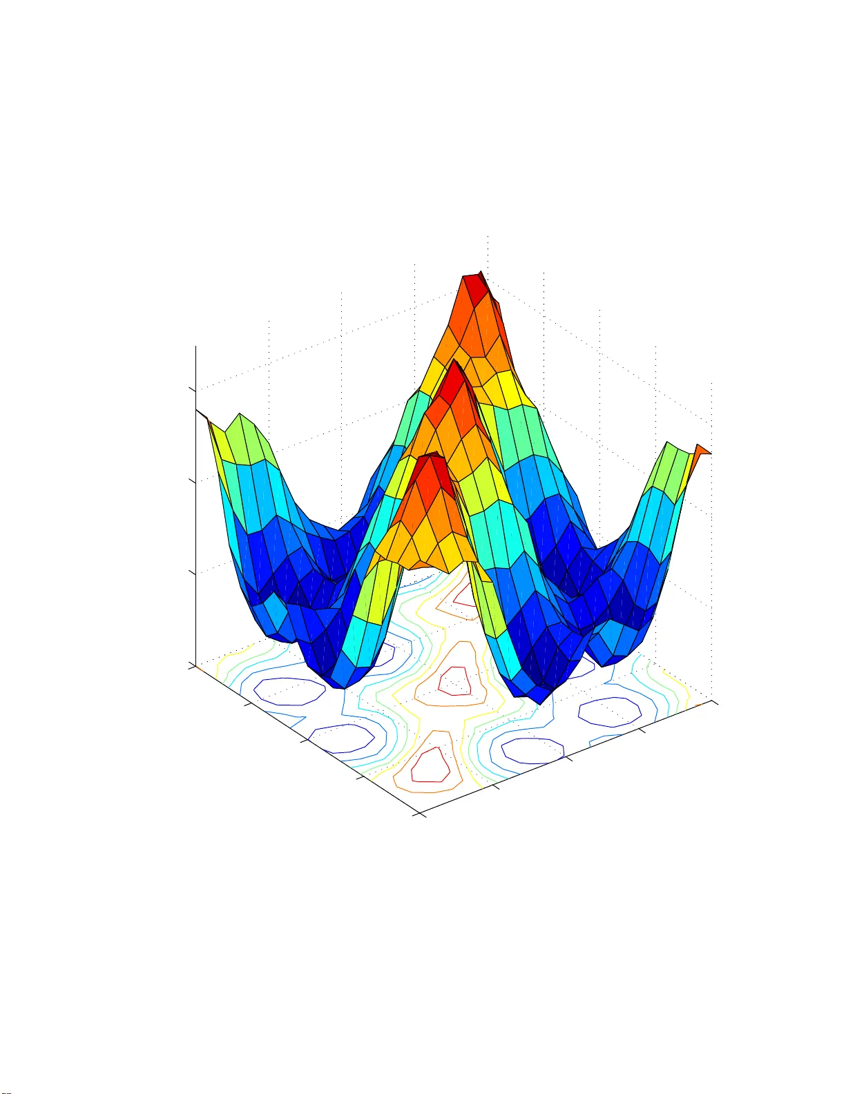
L2 OSTC-CPM: Theory and design Matthias Hesse ∗ , J ´ erˆ ome Lebrun and Luc D eneire Lab. I3S, CNRS, Unive rsit y of Nice, Sophia An tip olis, F rance E-Mail: { hesse,lebrun ,deneire } @i3s.unice.fr The combination of space-time co ding (STC) and contin uous phase mo dulation (CPM) is a n attractive field of resear ch bec ause bo th STC and CPM bring man y adv a n tages for wir eless comm unications. Zhang and Fitz [1] were the first to a pply this idea b y constr ucting a trellis based scheme. But for these co des the deco ding effort g rows exp onentially with the n um b er of transmitting an tennas. This w as circum ven ted by orthogonal co des intro duce d by W ang and Xia [2 ]. Unfortunately , based on Alamouti code [3], this design is r estricted to tw o antennas. How ev er, by relaxing the orthogona lit y condition, w e prov e here that it is p ossible to desig n L 2 -orthogo nal space- time co des which achiev e full rate and full diversit y with low deco ding effort. In part one, we generalize the tw o- antenna co de prop osed by W ang and Xia [2] from p oint wise to L 2 -orthogo nality and in part tw o we present the fir st L 2 -orthogo nal c o de for CP M with three an tennas. In this repo rt, we detail these r esults and fo cus on the prop erties of these codes . Of sp ecia l interest is the optimization of the bit error r ate whic h depends on the initial phase of the system. Our simulation r esults illustrate the systemic behavior of these co nditions. 1 P art one: Tw o an tennas case T o combine the high p ow er efficiency of Contin uous Phase Mo dulation (CPM) with either high spectra l efficiency or enhanced p erfor ma nce in low Signal to Noise c o nditions, some a uthors have prop osed to in tro duce CP M in a MIMO frame, b y using Spa c e Time Co des (STC). In this part, we addr ess the co de design pro blem of Space Time Blo ck Co des combined with CPM and introduce a new design cr iterion based on L 2 orthogo nalit y . This L 2 orthogo nalit y condition, with the help o f simplifying a ssumption, leads, in the 2x2 ca s e, to a new family of co des. These co des generalize the W ang and Xia code, which was based on point wise o rthogonality . Simulations indicate that the new co des achiev e full div ersity a nd a s light ly b etter coding gain. Mor e ov er, one of the co des can b e in terpreted as t wo antennas fed by tw o conv ent ional CPMs using the same data but with different alphab et sets. Insp e ction of these alphab et sets lead a lso to a simple ex planation of the (small) spectrum broadening of Space Time Co ded CP M. 1.1 In tro duction Since the pioneer work o f Alamouti [3] and T arokh [4], Space Time Co ding has been a fast growing field of research where numerous co ding schemes hav e be en intro duced. Several years later Zha ng and Fitz [1, 5] w ere the first to apply the idea of STC to contin uous phase modula tion (CP M) by cons tr ucting trellis co des. In [6] Za ji ´ c and St¨ uber derived conditions fo r par tia l resp onse STC- CPM to get full div ersity and optimal coding gain. A STC for noncoher en t detection based o n diagonal blo cks was intro duced by Silvester et al. [7]. The first orthogonal STC for CPM for full and partial resp onse was developed by W ang and Xia [8, 2]. The s cop e of this part is also the design of an or tho gonal STC for CPM. But unlik e W ang-Xia a prroach [2] whic h star ts from a QAM orthog onal Space- Time Code (e.g. Alamouti’s sc heme [3]) and mo dify it to achieve contin uous phases for the transmitted s ignals, w e show her e that a more ge neral L 2 condition is sufficient to ensure fast maximum lik eliho o d deco ding with full diversity . In the co nsidered system mo del (Fig. 1), the data sequence d j is defined over the signal co nstellation set Ω d = {− M + 1 , − M + 3 , . . . , M − 3 , M − 1 } (1) for an alphab e t with log 2 M bits. T o obtain the structure for a Space Time Blo ck Co de (STBC) this sequence is mapp ed to data matrice s D ( i ) with elemen ts d ( i ) mr , where m denotes the transmitting antenna, r the time slot in to a blo c k and ( i ) a parameter for pa r tial resp onse CPM. The data ma trices are then used to mo dulate the sending ma trix S ( t ) = s 11 ( t ) s 12 ( t ) s 21 ( t ) s 22 ( t ) . (2) ∗ The wo rk of Matthias Hesse is supported by a EU Marie-Cur i e F ello wship (EST-SIGNAL program : h ttp://est-signal.i3s.unice.fr) under con tract No MEST-CT-2005-021175. 1 Mapping d j d ( i ) 1 r d ( i ) 2 r Modulatio n s 1 r ( t ) s 2 r ( t ) ... ... ...dist... MLSE Detection ˆ d j y 1 ( t ) y n ( t ) y L r ( t ) Figure 1: Structure o f a MIMO Tx/Rx s ystem Each element is defined for (2 l + r − 1) T ≤ t ≤ (2 l + r ) T a s s mr ( t ) = r E s T e j 2 πφ mr ( t ) (3) where E s is the symbol energy and T the s y m b ol time. The phase φ mr ( t ) is defined in the conv en tional CPM ma nner [9] with an additional correction factor c mr ( t ) and is ther ewith given by φ mr ( t ) = θ m (2 l + r ) + h 2 l + r X i =2 l +1+ r − γ d ( i ) mr q ( t − ( i − 1) T ) + c mr ( t ) (4) where h = 2 m 0 /p with m 0 and p r elative primes is ca lled the mo dulation index. The phase s moo thing function q ( t ) has to b e a contin uous function with q ( t ) = 0 for t ≤ 0 and q ( t ) = 1 / 2 for t ≥ γ T . The memory length γ determines the leng th of q ( t ) a nd affects the sp ectral compactness. F or larg e γ we obtain a compact s pectr um but also a higher num ber o f p ossible phas e states which increases the deco ding effort. F or full resp onse CPM, we ha ve γ = 1 and for partial resp onse systems γ > 1. The c hoice of the cor rection factor c mr ( t ) in E q. (4) is along with the mapping of d j to D ( i ) , the k ey elemen t in the design of our coding scheme. It will b e detailed in Section 1.2. W e then define θ m (2 l + r ) in a mo st genera l wa y θ m (2 l + 3) = θ m (2 l + 2) + ξ (2 l + 2) = θ m (2 l + 1) + ξ (2 l + 1) + ξ (2 l + 2) . (5) The function ξ (2 l + r ) will be fully defined from the contribution c mr ( t ) to the phase memory θ m (2 l + r ). F or conv en tional CPM system, c mr ( t ) = 0 and we hav e ξ (2 l + 1) = h 2 d 2 l +1 − γ . The channel co efficients α mn are a ssumed to b e Rayleigh distributed and independent. Each coefficient α mn char- acterizes the fading b et ween the m th transmit (Tx) antenna and the n th receive (Rx) antenna wher e n = 1 , 2 , . . . , L r . F urthermore, the rece iv ed signals y n ( t ) = α mn s mr ( t ) + n ( t ) (6) are corrupted by a complex additive white Gaussian no ise n ( t ) with v ariance 1 / 2 p er dimension. A t the receiver, the detection is done on ea ch of the L r received signals separately . Therefore, in genera l, each co de blo ck S ( t ) has to be detected by blo ck. E.g. for a 2x2 blo c k, estimating the symbols ˆ d j implies co mputational complexity pr op o rtional to M 2 . Now, this complexity can b e reduced to 2 M b y intro ducing an orthogo nalit y prop erty as well as simplifying assumptions on the code. Criteria for suc h STBC are given in Section 1.2. In Section 1.3, the criteria are used to constr uct OSTBC for CPM. In Sectio n 1.4 we test the designed co de and compa re it with the STC from W ang and Xia [2]. Finally , some conclusions are drawn in Section 1.5. 1.2 Design Criteria The purp ose of the design is to a c hieve full diversity and a fast ma xim um likelihoo d deco ding while maintaining the con tinuit y of the signa l phases. This section sho ws how the need to p erform fast ML deco ding leads to the L 2 orthogo nalit y condition as well a s to simplifying assumptions, which can b e combined with the con tinuit y conditions. F or conv enience w e only co ns ider one Rx antenna and drop the index n in α mn . 1.2.1 F ast Maxim um Likeliho o d Deco ding Commonly , due to the trellis structure of CPM, the Viterbi alg orithm is used to per fo rm the ML demo dulatio n. O n blo c k l each state in the trellis has M 2 incoming branches a nd M 2 outgoing bra nc hes with a distance D l = (2 l +1) T Z 2 lT y ( t ) − 2 X m =1 α m s m 1 ( t ) 2 d t + (2 l +2) T Z (2 l +1) T y ( t ) − 2 X m =1 α m s m 2 ( t ) 2 d t. (7) 2 The num b er of bra nches r esults from the blo ckwise deco ding and the correla tion b et ween the sent symbols s 1 r ( t ) and s 2 r ( t ). A wa y to reduce the num ber of branches is to str ucturally deco r relate the signals sent by the t wo transmitting antennas, i.e. to put to zero the inter-antenna correla tion α 2 α ∗ 1 (2 l +1) T Z 2 lT s 21 ( t ) s ∗ 11 ( t ) d t + α 1 α ∗ 2 (2 l +1) T Z 2 lT s 11 ( t ) s ∗ 21 ( t ) d t + α 2 α ∗ 1 (2 l +2) T Z (2 l +1) T s 22 ( t ) s ∗ 12 ( t ) d t + α 1 α ∗ 2 (2 l +2) T Z (2 l +1) T s 12 ( t ) s ∗ 22 ( t ) d t = 0 . (8) Poin t wise or thogonality as defined in [2] is therefore a sufficient condition but not necessa ry . A less restrictive L 2 orthogo nalit y is a lso sufficient. F ro m Eq. (8), the distance giv en in Eq. (7) ca n then be simplified to D l = (2 l +1) T Z 2 lT f 11 ( t ) + f 21 ( t ) − | y ( t ) | 2 d t + (2 l +2) T Z (2 l +1) T f 12 ( t ) + f 22 ( t ) − | y ( t ) | 2 d t (9) with f mr ( t ) = | y ( t ) − α m s mr ( t ) | 2 . When each s mr ( t ) dep ends o nly on d 2 l +1 or d 2 l +2 the bra nc hes can b e s plit and calculated separately for d 2 l +1 and d 2 l +2 . The complexity of the ML decision is r educed to 2 M . The complexity for detecting tw o sym b ols is thus r educed from pM γ +1 to pM γ . The STC int ro duced by W ang and Xia [2] didn’t tak e full adv an tage of the orthogona l design s ince s mr ( t ) was dep ending on b oth d 2 l +1 and d 2 l +2 . The gain they obtained in [2 ] was then relying on other prop erties of CPM, e.g. so me restrictio ns put on q ( t ) and p . These restrictions may also be applied to our des ign co de, which would lead to additiona l complexity reduction. 1.2.2 Orthogonality Co ndition In this section w e sho w ho w L 2 orthogo nalit y for CPM, i.e. k S ( t ) k 2 L 2 = R (2 l +2) T 2 lT S ( t ) S H ( t ) d t = 2 I , can be obtained. As such, the correlation betw een the t w o trans mitting a n tennas p er co ding blo ck is canceled if (2 l +2) T Z 2 lT s 1 r ( t ) s ∗ 2 r ( t ) d t = (2 l +1) T Z 2 lT s 11 ( t ) s ∗ 21 ( t ) d t + (2 l +2) T Z (2 l +1) T s 12 ( t ) s ∗ 22 ( t ) d t = 0. (10) Replacing s mr ( t ) by the corre s po nding CPM sy mbo ls from Eq. (4), we g et (2 l +1) T Z 2 lT exp n j 2 π ˆ θ 1 (2 l + 1) + h 2 l +1 X i =2 l +2 − γ d ( i ) 1 , 1 q ( t − ( i − 1) T ) + c 1 , 1 ( t ) − θ 2 (2 l + 1) − h 2 l +2 X i =2 l +3 − γ d ( i ) 2 , 1 q ( t − ( i − 1) T ) − c 2 , 1 ( t ) ˜ o d t + (2 l +2) T Z (2 l +1) T exp n j 2 π ˆ θ 1 (2 l + 2) + h 2 l +2 X i =2 l +3 − γ d ( i ) 1 , 2 q ( t − ( i − 1) T ) + c 1 , 2 ( t ) − θ 2 (2 l + 2) − h 2 l +1 X i =2 l +2 − γ d ( i +1) 2 , 2 q ( t − iT ) − c 2 , 2 ( t ) ˜ d t o = 0 . (11) The pha se memory θ m (2 l + r ) is independent of time and has no t to b e considered for in tegratio n. Using Eq. (5) to replace phase memory θ m (2 l + 2) of the seco nd time slot, w e o btain (2 l +1) T Z 2 lT exp n j 2 π ˆ h 2 l +1 X i =2 l +2 − γ d ( i ) 1 , 1 q ( t − ( i − 1) T ) + c 1 , 1 ( t ) − h 2 l +1 X i =2 l +2 − γ d ( i ) 2 , 1 q ( t − ( i − 1) T ) − c 2 , 1 ( t ) ˜ o d t + exp n j 2 π ˆ ξ 1 (2 l + 1) − ξ 2 (2 l + 1) ˜ o · (2 l +1) T Z 2 lT exp n j 2 π ˆ h 2 l +1 X i =2 l +2 − γ d ( i +1) 1 , 2 q ( t − ( i − 1) T ) + c 1 , 2 ( t + T ) − h 2 l +1 X i =2 l +2 − γ d ( i +1) 2 , 2 q ( t − ( i − 1) T ) − c 2 , 2 ( t + T ) ˜ o d t = 0 . (12) 1.2.3 Simplifyi ng assum ptions T o simplify this expres sion, we factor Eq. (12) into a time indepe nden t and a time dep endent part. F or merging the t wo integrals to o ne time dep endent par t, we have to map d ( i ) m 2 to d ( i ) m 1 and c mr ( t ) to a different c m ′ r ′ ( t ). Consequently , for the data s ym b ols d ( i ) mr there exis t three pos sible wa ys o f mapping: • cr osswise m apping with d ( i ) 1 , 1 = d ( i ) 2 , 2 and d ( i ) 1 , 2 = d ( i ) 2 , 1 ; • r ep etitive mapping with d ( i ) 1 , 1 = d ( i ) 1 , 2 and d ( i ) 2 , 1 = d ( i ) 2 , 2 ; • p ar al lel mapping with d ( i ) 1 , 1 = d ( i ) 2 , 1 and d ( i ) 1 , 2 = d ( i ) 2 , 2 . 3 The same approa ch ca n be applied to c mr ( t ): • cr osswise m apping with c 11 ( t ) = − c 22 ( t − T ) and c 12 ( t ) = − c 21 ( t − T ); • r ep etitive mapping with c 11 ( t ) = c 12 ( t − T ) and c 21 ( t ) = c 22 ( t − T ); • p ar al lel mapping with c 11 ( t ) = c 21 ( t ) and c 12 ( t ) = c 22 ( t ). F or each c o m bination o f mappings, E q. (1 2) is now the pro duct of tw o fac to rs, one containing the integral and the other a time indep endent part. T o fulfill Eq. (12) it is sufficient if one factor is zero , na mely 1 + e j 2 π [ ξ 1 (2 l +1) − ξ 2 (2 l +1)] = 0, i.e. if k + 1 2 = ξ 1 (2 l + 1) − ξ 2 (2 l + 1) (13) with k ∈ N . W e thus get a very simple condition which o nly dep ends on ξ m (2 l + 1). 1.2.4 Con tin uity of Phase In this section w e determine the functions ξ m (2 l + 1) to ensure the phase co n tinuit y . Precisely , the phase of the CPM sym b ols has to be e q ual at all in tersections of symbo ls. F or a n a rbitrary blo ck l , it means that φ m 1 ((2 l + 1) T ) = φ m 2 ((2 l + 1) T ). Using Eq. (4), it results in ξ m (2 l + 1) = h 2 l +1 X i =2 l +2 − γ d ( i ) m, 1 q ((2 l + 2 − i ) T ) + c m, 1 ((2 l + 1) T ) − h 2 l +2 X i =2 l +3 − γ d ( i ) m 2 q ((2 l + 2 − i ) T ) − c m, 2 ((2 l + 1) T ). (14) F or the seco nd in tersection a t (2 l + 2) T , since φ m 2 ((2 l + 2) T ) = φ m 1 ((2 l + 2) T ), we get ξ m (2 l + 2) = h 2 l +2 X i =2 l +3 − γ d ( i ) m 2 q ((2 l + 3 − i ) T ) + c m 2 ((2 l + 2) T ) − h 2( l +1)+1 X i =2( l +1)+2 − γ d ( i ) m, 1 q ((2 l + 3 − i ) T ) − c m, 1 ((2 l + 2) T ). (15) Now, b y choosing one of the ma ppings detailed in Section 1.3, these equations can b e g r eatly simplified. Hence, we hav e all the to ols to construct our co de. 1.3 Orthogonal Space Time Co des In this section w e will hav e a closer lo ok at t w o co des constr ucted under the afore- men tioned conditions. 1.3.1 Existing Co de As a first example, we will giv e an alterna tiv e construction of the code given by W ang and Xia in [2]. Indeed, the po in twise orthogonality co ndition used by W ang and Xia is a spec ia l case o f the L 2 orthogo nalit y condition, hence, their ST-co de ca n b e obtained within our framework. F or the first a n tenna W ang and Xia use a con ven tional CPM with d ( i ) 1 r = d i for i = 2 l + r + 1 − γ , 2 l + r + 2 − γ , . . . , 2 l + r and c 1 r ( t ) = 0. The symbo ls o f the seco nd an tenna are mapped cr osswise to the first d ( i ) 21 = − d i +1 for i = 2 l + 2 − γ , 2 l + 3 − γ , . . . , 2 l + 1 a nd d ( i − 1) 22 = − d i − 1 for i = 2 l + 3 − γ , 2 l + 4 − γ , . . . , 2 l + 2. Using this cross mapping makes it difficult to co mpute ξ m (2 l + 1) since the CP M t ypical order of the data symbols is mixed. W ang and Xia circ umven t this by in tro ducing a nother correction factor for the second antenna c 2 r ( t ) = γ − 1 X i =0 ( h ( d 2 l +1 − i + d 2 l +2 − i ) + 1) q 0 ( t − (2 l + r − 1 − i ) T ) . (16) By first computing ξ m (2 l + 1) with Eq. (17) and then Eq. (13), we get the L 2 orthogo nalit y o f the W ang-Xia- STC. 1.3.2 P arallel Co de T o get a simpler co rrection factor as in [2], w e desig ned a new code based o n the p ar al lel structure whic h permits to maintain the co n ven tional CPM mapping for b oth a ntennas. Hence we cho ose the following mapping: d ( i ) m 1 = d ( i − 1) m 2 = d i for i = 2 l + r + 1 − γ , 2 l + r + 2 − γ , . . . , 2 l + r . Then, Eq. (14) and (15 ) can b e simplified in to ξ m (2 l + 1) = h 2 d 2 l +2 − γ + c m 1 ((2 l + 1 ) T ) − c m 2 ((2 l + 1 ) T ) ξ m (2 l + 2) = h 2 d 2 l +3 − γ + c m 2 ((2 l + 2 ) T ) − c m 1 ((2 l + 2 ) T ). (17) 4 P S f r a g r e p l a c e m e n t s E b / N 0 [dB] BER 3 T x , o ff P C 1 Tx 2 Tx, o ffPC 3 Tx, linPC 3 Tx, o ffPC 0 0 . 1 0 . 2 0 . 3 0 . 4 0 . 5 0 . 6 0 . 7 0 . 8 0 . 9 1 5 7.5 10 12.5 15 17.5 20 22.5 25 27.5 0 0 . 1 0 . 2 0 . 3 0 . 4 0 . 5 0 . 6 0 . 7 0 . 8 0 . 9 1 10 − 6 10 − 5 10 − 4 10 − 3 10 − 2 10 − 1 10 0 P S f r a g r e p l a c e m e n t s Normalized F requenzy f · T b Po wer 2 n d T x a n t . W a n g 1 st Tx ant. 2 nd Tx ant. 1 st Tx ant. W ang 2 nd Tx ant. W ang 1 st antenna 2 nd antenna 1 st antenna 0 0 . 1 0 . 2 0 . 3 0 . 4 0 . 5 0 . 6 0 . 7 0 . 8 0 . 9 1 -6 -4 -2 0 2 4 6 0 0 . 1 0 . 2 0 . 3 0 . 4 0 . 5 0 . 6 0 . 7 0 . 8 0 . 9 1 10 − 6 10 − 5 10 − 4 10 − 3 10 − 2 10 − 1 Figure 2: Left: Sim ulated BER for different num b ers of Tx and Rx antennas of the prop osed STC and of the W ang-Xia-STC; Right: Simulated psd for each Tx antenna of the prop osed STC (contin uous line) and the W ang-X ia-STC ( d ashed line) With this simplified functions, the orthog o nality condition only depends on the start and end v a lues of c mr ( t ), i.e. k + 1 2 = c 11 ((2 l + 1) T ) − c 12 ((2 l + 1) T ) − c 21 ((2 l + 1) T ) + c 22 ((2 l + 1) T ) . (18) T o merge the t wo integrals in Eq. (12), the mapping of d ( i ) mr is necessa ry but a ls o a n equality b etw een different c mr ( t ). F rom the three possible mappings , we choo se the r ep e at mapp ing beca use of the p ossibility to set c mr ( t ) to zero for one antenna. Hence we a re able to s end a conv entional CPM signa l on o ne antenna and a mo dified one on the s econd. Using Eq. (18) a nd the equalities for the mapping , w e can formulate the following condition k + 1 2 = c 12 (2 l T ) − c 12 ((2 l + 1) T ) − c 22 (2 l T ) + c 22 ((2 l + 1) T ) . (19) With c 11 ( t ) = c 12 ( t ) = 0 , we can take fo r c 21 ( t ) = c 22 ( t ) an y contin uous function which is zero at t = 0 and 1 / 2 at t = T . Another po ssibility is to c ho ose the co rrection fa ctor of the seco nd antenna with a structure similar to CPM mo dulation, i.e. c 2 r ( t ) = 2 l +1 X i =2 l +1 − γ q ( t − ( i − 1) T ) (20) for (2 l + r − 1) T ≤ t ≤ (2 l + r ) T . With this appr oach, the c o rrection factors can b e included in a classica l CP M mo dulation with constant offset of 1 /h . This o ffset may a lso b e expr e ssed as a mo dified alphab et for the second antenna Ω d 2 = {− M + 1 + 1 h , − M + 3 + 1 h , . . . , M − 3 + 1 h , M − 1 + 1 h } . (21) Consequently , this L 2 -orthogo nal desig n ma y b e seen as tw o conv en tional CPM designs with different alphabe t sets Ω d and Ω d 2 for each antenna. How ever, in this metho d, the constant offset to the phase may cause a shift in frequency . But as shown by our simulations in the next section, this shift is q uite mo derate. 1.4 Sim ulations In this sectio n we verify the prop osed algor ithm by simulations. Therefore a STC-2 REC-CPM-se nder with tw o transmitting antennas has been implemented in MA TLAB. F or the signal of the first antenna we use c o n ven tional Gray-co ded CPM with a mo dulation index h = 1 / 2 , the length of the phase resp onse function γ = 2 and a n alphab et size of M = 8. The sig nal of the second ant enna is mo dulated by a CPM with the same parameter s but a differen t alphab et Ω d 2 , corr esp onding to Eq. (21). The channel used is a frequency flat Rayleigh fading mo del with additive white Ga ussian noise. The fading co efficients α mn are constant for the duration o f a co de blo ck (block fading) and known a t receiver (coherent detection). The received signal y n ( t ) is de mo dulated by t wo filterbanks with pM 2 filters, which are used to ca lculate the cor relation betw een the r eceived and ca ndidate signa ls . Due to the o rthogonality of the antennas each filterba nk is indep endently 5 Mapping Modulatio n ... ... ...dist... MLSE Detection d j d ( l,i ) 1 ,r d ( l,i ) 2 ,r d ( l,i ) 3 ,r s 3 ,r ( t ) s 2 ,r ( t ) s 1 ,r ( t ) y 1 ,r ( t ) y L r ,r ( t ) y n,r ( t ) ˆ d j Figure 3: Structure o f a MIMO Tx/Rx s ystem applied to the corr esp o nding time slot k of the block co de. The cor relation is used as metric for the Viterbi alg orithm (V A) whic h has pM states a nd M paths le aving each state. In our s im ulation, the V A is truncated to a path memory of 10 co de blo cks, which means that w e get a deco ding delay of 2 · 10 T . F rom the sim ulation results given in Figure 2, we ca n reas onably a ssume that the prop osed co de achieves full diversit y . Indeed, the curves for the 2x1 and 2x2 sys tems resp ectively s how a slop e of 2 and 4. Moreover, the curve of the 2x1 s y stems follows the same slop e as the ST co de prop osed by W ang and Xia [2], which was prov ed to hav e full diversit y . Note a lso that the new co de pro vides a slightly b etter perfor mance. A main re ason of using CP M for STC is the sp ectral efficiency . Figure 2 show the simulated p ow er sp ectra l density (psd) for b oth Tx antennas of the prop osed ST c ode (contin uous line) a nd the ST co de pro po s ed by W ang and Xia [2]. The first antenna o f our approach uses a conv entional CPM sig na l and hence shows an equal psd. The sp ectrum of the seco nd a ntenna is s hifted due to adding an offset c mr ( t ) with a non z e ro mean. Minimizing the difference b etw een the t wo spectr a by shifting one , result in a phase difference of 0 . 375 mea s ured in normalized frequency f · T d , where T d = T / lo g 2 ( M ) is the bit sym b ol length. The fir st antenna of the W ang-Xia -algorithm has almost the same psd while the sp ectrum o f the second antenna is shifted by appr oximately 0 . 56 f · T d . T his means that the O STC b y W ang and Xia req uires a slightly lar ger bandwidth than our OSTC. 1.5 Conclusion to part one In applications where the p ow er efficiency is crucia l, combination o f Contin uous P ha se Modula tion and Space Time Co ding has the p otential to provide high sp ectral efficiency , thanks to spatial diversit y . T o addres s this power efficiency , ST co de design for CPM has to ensure b oth low co mplexit y deco ding and full diversit y . T o fulfill these requir emen ts, we ha ve pro pos ed a new L 2 orthogo nalit y condition. W e ha ve shown that this condition is s ufficien t to ac hieve low complexity ML deco ding a nd leads, with the help of simplifying assumption to a simple co de. Mor eov er, s imulations indicate that the co de mos t probably achiev es full diversity . In the next part o f this repo r t, we will concentrate on the desig n of o ther co des ba sed on L 2 orthogo nalit y and will show how to design full diversit y , full rate L 2 orthogo nal co des for 3 antennas. 2 P art t w o: Extension to more an tennas T o combine the power efficiency o f Contin uous P hase Mo dulation (CPM) with enhanced p erformance in fading envi- ronments, some authors ha ve sugges ted to use CPM in com bination with Space - Time Co des (STC). In part one, we hav e prop osed a CPM ST-co ding scheme bases on L 2 -orthogo nality for tw o trans mitting antennas. In this pa rt we ex- tend this approach to the three antenna case . W e analytica lly derive a fa mily o f co ding schemes which we ca ll Parallel Co de (P C). This co de family has full ra te a nd w e exp ect that the pro p os e d co ding scheme a ch ieves full diversit y . T his is confirmed by accompanying simulations. W e detail an example for the propos ed STC whic h c a n b e in terpreted as a conv en tional CPM scheme with different alphab et sets for the different transmit antennas which results in simpli- fied implementation. Thanks to L 2 -orthogo nality , the decoding complexit y , usually exp onentially prop ortional to the nu mber of transmitting ant ennas, is r e duced to linear co mplexit y . 2.1 In tro duction T o ov erco me the reduction of channel capacity caused by fading, T e latar [10], F oschini and Gans [11] describ ed in the late 90s the p otential gain of switchin g to m ultiple input multiple output (MIMO) systems. These r esults triggered many adv ances mostly c oncent rated on the co ding asp ects for transmitting antennas, e.g. Alamouti [3] and T aro kh et al. [4] for Spac e - Time Blo c k Co des (STBC) a nd also T aro k h et a l. [1 2] for Space-Time T r e llis Codes. Zhang and Fitz [1, 5] were the fir st to apply the idea o f STC to CP M by constructing trellis co des. In [7], Silvester et al. derived a diagonal blo ck spa c e -time co de which ena bles non- coherent detection. A condition fo r optimal co ding gain while sustaining full diversit y was also recently de r ived by Za ji ´ c and St ¨ ub er [6]. 6 Inspired by o r thogonal desig n co des, W ang and Xia intro duced in [8] the first or thogonal STC for tw o transmitting antennas and full re spo nse CPM and later in [2 ] for pa rtial resp onse. Their appr oach w as extended in [13] to construct a pseudo - orthogona l ST-co ded CPM for four ant ennas. T o avoid the structural limitation of ortho gonal design, we pro pos ed in [14] a STC CP M scheme based on L 2 orthogo nalit y for tw o antennas. Sufficien t co nditio ns for L 2 orthogo nalit y were describ ed, L 2 orthogo nal co des were intro duced and the simulation results display ed go o d per formance and full ra te. Here, motiv ated b y this results, we extend our previous work and g eneralize these co nditions for three transmitting an tenna. The main result of the three transmit antenna ca se, is that it can, unlik e the c odes based on orthog o nal design, achiev e full div ersity with a full rate co de: 1. the ful l rate prop ert y is one of the ma in a dv antage of using the L 2 norm criterio n, instea d o f mer e ly ex tending the cla s sical T arokh [4] orthogo na l des ign to the CPM ca s e. Indeed, in the cla ssical orthog onal desig n approa c h, which is based on o ptimal deco ding for linear mo dulations, the cr iter ion is expressed as the or tho gonality b etw een matrices o f element s, each of these elemen ts b eing a definite in tegral (usually the output of a matched filter). On the co n trar y , in the L 2 design a ppr oach used for non- line a r mo dulations, the pro duct in Eq . (29) is a definite int egra l itself, the integrand b eing the pr oduct o f t wo signa ls. T his allo ws more deg rees of freedom and ena bles the full rate pro per t y . 2. the full di v ersit y prop ert y can b e prov ed in a similar wa y to the classic al case , with the help of the extensions prop osed by Za ji ´ c and St ¨ ub er [6]. F urthermore, it should be p ointed out that the prop osed co ding scheme do es not limit any para meter of the CPM. It is applicable to full and partial res pons e CPM as well as to all mo dulation indexes. W e first give the system model for a multiple input m ultiple o utput (MIMO) s ystem with L t transmitting (Tx) antennas a nd L r receiving (Rx) an tennas (Fig. 3). L a ter on, we will use this general mo del to derive a L2-OSTC for CPM for L t = 3 . The emitted sig na ls s ( t ) are mixed b y a ch annel matrix A of dimensio n L r × L t . The elemen ts of A , α n,m , are Rayleigh dis tributed random v a r iables and c haracter iz e the fading betw een the n th Rx and the m th Tx antenna. The Tx signal is distur b ed b y complex additive white Gaus s ian noise (A W GN) with v aria nce o f 1 / 2 per dimension which is represented by a L r × L t matrix n ( t ). The received signal y ( t ) = As ( t ) + n ( t ) . (22) has the elements y n,r and the dimensio n L r × L t . W e gro up the tr ansmitted CPM signa ls into blo cks s ( t ) = s 1 , 1 ( t ) . . . s 1 ,L t ( t ) . . . s m,r ( t ) . . . s L t , 1 ( t ) . . . s L t ,L t ( t ) (23) similar to a ST blo ck co de with the difference that now the elements are functions of time and not cons tan t anymore. The elements o f E q. (23) are g iven by s m,r ( t ) = r E s L t T exp ( j 2 π φ m,r ( t )) (24) for ( L t l + r − 1) T ≤ t ≤ ( L t l + r ) T and m, r = 1 , 2 , . . . , L t . Here m represents the tr ansmitting a ntenna and r the relative time slo t in the block. The symbol energ y E s is no rmalized to the num ber of Tx antennas L t and the symbol length T . The contin uous phase φ m,r ( t ) = θ m ( L t l + r ) + h γ X i =1 d ( l,i ) m,r q ( t − i ′ T ) + c m,r ( t ) (25) is defined similarly to [9] with an additio na l correctio n factor c m,r ( t ) detailed in Section 2 .2.3. F urthermore, l is indexing the who le co de blo ck, i the ov erlapping s ym b ols for pa rtial resp onse and i ′ = L t l + r − i . With this extensive description of the s y m b ol d ( l,i ) m,r , we ar e a ble to define all p ossible mapping schemes (cp. Section 2 .2.2). The mo dulation index h = 2 m 0 /p is the quo tien t of tw o relative prime in tegers m 0 and p a nd the phase smo othing function q ( t ) has to be con tinuous for 0 ≤ t ≤ γ T , 0 for t ≤ 0 and 1 / 2 ≤ γ T . The memory leng th γ gives the num be r o f o verlapping symbols. T o maintain contin uit y of phase, we define the phase memo ry θ m ( L t l + r + 1) = θ m ( L t l + r ) + ξ m ( L t l + r ) (26) 7 in a general way . The function ξ ( L t l + r ) will b e fully defined in Section 2.2.3 from the con tribution of c mr ( t ). F or a conv en tional CPM system, we hav e c mr ( t ) = 0 and ξ (2 l + 1) = h 2 d 2 l +1 − γ . In Section 2.2, we der ive the L 2 conditions for a CPM with thr e e transmitting an tennas and introduce adequate mappings and a family of co rrection factors. In Sectio n 2 .3, we detail some pr op erties of the co de. In Section 2.4 , w e benchmark the co de by running so me s im ulations and finally , in Section 2.5, some c o nclusions are drawn. 2.2 P arallel Co des ( PC) for 3 an tennas 2.2.1 L 2 Orthogonality In this section w e des crib e how to enfor ce L 2 orthogo nalit y on CPM systems with three transmitting antennas. Similarly to [14], we impo se L 2 orthogo nalit y b y (3 l +3) T Z 3 lT s ( t ) s H ( t ) d t = E S I (27) where I is the 3 × 3 identit y ma trix. Hence the correlatio n b etw een tw o different Tx a ntennas s m,r ( t ) and s m ′ ,r ( t ) is canceled ov er a complete STC blo ck if (3 l +3) T Z 3 lT s m,r ( t ) s ∗ m ′ ,r ( t ) d t = 0 (28) with m 6 = m ′ . Now, by us ing Eq. (24) and (25) we get 0 = 3 X r =1 (3 l + r ) T Z (3 l + r − 1) T exp j 2 π · θ m (3 l + r ) + h γ X i =1 d ( l,i ) m,r q ( t − i ′ T ) + c m,r ( t ) − ( θ m ′ (3 l + r ) − h γ X i =1 d ( l,i ) m ′ ,r q ( t − i ′ T ) − c m ′ ,r ( t )) d t. (29) The phase memory θ m (3 l + r ) is time independent and therewith can be mo ved to a c o nstant fa c to r in front of the int egra ls. Similarly to [14], we introduce p ar al lel mapping ( d ( l,i ) m,r = d ( l,i ) m ′ ,r ) for the data symbols and r ep etitive mapp ing ( c m,r ( t ) = c m,r ′ ( t )) for the cor rection factors . The in tegral o n three time slots c an then b e merged into one time depe ndent factor. F ur ther more, we obta in a second, time independent factor from the phase memory . Now, by using Eq. (26) one ca n see that the co ndition from Eq. (29) is fulfilled if 0 = 1 + exp( j a 1 ) + exp( j a 1 ) exp( j a 2 ) (30) where a r = 2 π [ ξ m (3 l + r ) − ξ m ′ (3 l + r )] and we get − exp( − j a 1 ) = 1 + exp( j a 2 ). By splitting this equation in to imaginary and rea l parts, we have the follo wing tw o conditions: − 1 = co s( − a 1 ) + co s( a 2 ) (31) 0 = sin( − a 1 ) + sin( a 2 ) . (32) This system has , modulo 2 π , t wo pair s of solutions ( a 1 , a 2 ) ∈ { (2 π / 3 , 2 π / 3) , (4 π / 3 , 4 π / 3) } . (33) Hence L 2 orthogo nalit y is a c hieved if ξ m (3 l + r ) − ξ m ′ (3 l + r ) = 1 / 3 or ξ m (3 l + r ) − ξ m ′ (3 l + r ) = 2 / 3 for r = 1 , 2 and for all c o m binations of m and m ′ with m 6 = m ′ . I n order to de ter mine ξ m (3 l + r ), w e detail in the following s ection the exact mapping a nd the cor rection factor . 2.2.2 Mapping In this section we descr ibe the ma pping of the data sequence d j to the data symbols d ( l, 1) m,r of the blo ck co de (Fig. 4). T o obtain full rate each c o de blo ck hav e to include three new symbols from the data se quence. In general, the mapping of the three new sym b ols has no r estrictions. How ev er, to fix a mapping t w o criter ia a re considered: • mapping to simplify Eq. (2 9) • low complexity of function ξ m (3 l + r ). 8 d ( l, 2) 3 , 3 d ( l, 2) 2 , 3 r m i d ( l, 1) 1 , 1 d ( l, 1) 2 , 1 d ( l, 1) 3 , 1 d ( l, 1) 1 , 2 d ( l, 1) 2 , 2 d ( l, 1) 3 , 2 d ( l, 1) 1 , 3 d ( l, 1) 2 , 3 d ( l, 1) 3 , 3 d ( l, 2) 1 , 1 d ( l, 2) 1 , 3 d ( l, 2) 1 , 2 d 3 l +1 d 3 l +3 t d 3 l +2 d 3 l block of data symbo ls data sequence Figure 4: Mapping o f the data s e q uence to the data symbols The first criteria is a lready determined b y us ing p ar al lel mapp ing ( d ( l,i ) m,r = d ( l,i ) m ′ ,r ). Therewith the mapping for the m -dimension (Fig. 4) is fixed. F or the r emaining tw o dimensions we c ho ose a mapping s imilar to conv entional CPM. The subsequent data symbols in r -directio n are mapp ed to subsequen t symbols from the data sequence. Also similar to conv ent ional CPM we s hift this ma pping b y − i and obtain d ( l,i ) m,r = d 3 l + r − i +1 . (34) Eq. (35) and (36) s how the simplifica tio n of the function ξ m (3 l + r ). 2.2.3 Correction F actor The choice of the phase memo r y and there with of the function ξ m (3 l + r ) e ns ures the contin uity of phase. If φ m,r (( L t l + r ) T ) = φ m,r +1 (( L t l + r ) T ), we a lw ays obtain the desired contin uit y . Hence, ξ m ( L t l + r ) = h γ X i =1 d ( l,i ) m,r q ( iT ) + c m,r ((3 l + r ) T ) − h γ X i =1 d ( l,i ) m,r +1 q ( iT ) − c m,r +1 ((3 l + r ) T ) . (35) With a mapping similar to co n ven tional CP M (Section 2 .2.2) we ca n simplify the tw o sums to a sing le ter m and o btain for r = 1 , 2 ξ m (3 l + r ) = h 2 d 3 l + r − γ +1 + c m,r ((3 l + r ) T ) − c m,r +1 ((3 l + r ) T ) . (36) As the data sym bo ls are equal on ea c h antenna, the differe nc e b etw een t wo different ξ m (3 l + r ) do es not dep end on the da ta symbol d 3 l + r − γ +1 . Thus, when choosing p ar al lel mapping , L 2 orthogo nalit y only depends on the correction factor. T o fulfill E q. (3 0) for all a n tennas we take • for m = 1, m ′ = 2 a r = 2 π 3 = 2 π [ c 1 ,r ((3 l + r ) T ) − c 1 ,r +1 ((3 l + r ) T ) − c 2 ,r ((3 l + r ) T ) + c 2 ,r +1 ((3 l + r ) T )] , (37) • for m = 2, m ′ = 3 a r = 2 π 3 = 2 π [ c 2 ,r ((3 l + r ) T ) − c 2 ,r +1 ((3 l + r ) T ) − c 3 ,r ((3 l + r ) T ) + c 3 ,r +1 ((3 l + r ) T )] (38) • and for m = 1, m ′ = 3 we consequently g et a r = 4 π 3 = 2 π [ c 1 ,r ((3 l + r ) T ) − c 1 ,r +1 ((3 l + r ) T ) − c 3 ,r ((3 l + r ) T ) + c 3 ,r +1 ((3 l + r ) T )] . (39) The other three p oss ible combinations of m a nd m ′ with m 6 = m ′ lead o nly to a change of sign and we get a r = − 2 π / 3 , − 2 π / 3 , − 4 π / 3, resp ectively . Due to the modulo 2 π character of our co ndition, these are a lso v alid solutions. 9 F or simplicit y , we assume similar cor r ection fac to rs for each time slot r of one Tx antenna c m, 1 ( t ) = c m, 2 ( t ) = c m, 3 ( t ). Since Eq. (3 9) ar ises from Eq. (37) and (38), w e have tw o equa tions and three parameters: c 1 ,r ( t ), c 2 ,r ( t ) and c 3 ,r ( t ). Hence we define c 2 ,r ( t ) = 0 for r = 1 , 2 , 3 and w e get c 1 ,r ((3 l + r ) T ) − c 1 ,r +1 ((3 l + r ) T ) = 1 / 3 and c 3 ,r ((3 l + r ) T ) − c 3 ,r +1 ((3 l + r ) T ) = − 1 / 3 for r = 1 , 2. Co des fulfilling thes e conditions for m the family o f Parallel Co des (PC). W e will no w describ e some p ossible s olutions of this family . An ob vious so lutio n for the correction factor is obta ine d for a ll functions which are 0 for t = (3 l + r ) T and ± 1 / 3 for t = (3 l + r + 1) T , e.g. c 1 ,r ( t ) = − c 3 ,r ( t ) = 2 3 · t − (3 l + r ) T 2 T (40) for (3 l + r ) T ≤ t ≤ (3 l + r + 1) T . W e denote this solution as linear parallel co de (linPC). O f cours e, other choices are po ssible, e.g. based o n raised cosine (rcPC). Another way of defining the co rrection factor is c 1 ,r ( t ) = − c 3 ,r ( t ) = γ X i =1 2 3 q ( t − i ′ T ) (41) for (3 l + r ) T ≤ t ≤ (3 l + r + 1) T . In that ca se we ta ke adv ant age of the na tur al s tructure of CPM, i.e. in Eq. (35) all except one summands cancel down, similar to the terms with the data sy m b ols. This definition has the adv antage that we c a n merg e the corre c tion factor and the data sy m b ol in E q. (2 5) and we obta in tw o pseudo a lphabets shifted by an offset (offPC) for the first a nd thir d transmitting an tenna Ω d 1 = − M + 1 + 2 3 h , − M + 3 + 2 3 h , . . . , M − 1 + 2 3 h Ω d 3 = − M + 1 − 2 3 h , − M + 3 − 2 3 h , . . . , M − 1 − 2 3 h . Consequently , this L 2 -orthogo nal design ma y b e s e en as three c onv en tional CPM sig na ls with different alphab et sets Ω d , Ω d 1 and Ω d 3 for eac h a n tenna. In this method, the constant phase offsets introduce frequency shifts. But a s shown by the simulations in next s e ction, these shifts a re quite mo derate. 2.3 Prop erties of PC CPM 2.3.1 Deco ding The optimal r eceiver for the prop osed codes relies on the computation of a metric ov er complete ST blo cks follow ed by a maximum-likelihoo d sequence estimation (MLSE). Here, the metric is ev a luated using the L 2 norm D 1 = (3 l +3) T Z 3 lT y 1 ,r ( t ) − 3 X m =1 α 1 ,m s m,r ( t ) 2 d t. (42) F or co n venience, we us e here only one receiving antenna but the extension to more than one is straightforward. T he distance in E q. (42) is obtained for all pM γ + L t − 1 po ssible v ariations of s m,r ( t ) corr espo nding to the paths o f the trellis. The num b er of states ca n b e reduced in tw o wa ys. First, by using the orthogo nalit y prop erty o f the prop ose d co de, all cross - correlatio ns in E q . (42) are cance le d out and we obta in D 2 = 3 X m =0 3 X r =0 (3 l + r +1) T Z (3 l + r ) T y 1 ,r ( t ) − α 1 ,m s m,r ( t ) 2 d t. (43) W e o nly have to co nsider pM γ paths for every s m,r ( t ). The complex it y of computing the dis tance is ther ewith L 2 t pM γ which corr esp o nds to the necessary effort to deco de three symbols of three C P M signals. Second, by taking adv antage of the p ar al lel mapping w e are not forced to deco de blo ck-wise. W e can compute the distances symbol-wis e with D 3 = ( β +1) T Z β T y 1 ,r ( t ) − 3 X m =1 α 1 ,m s m,r ( t ) 2 d t (44) 10 P S f r a g r e p l a c e m e n t s θ 1 (0) θ 2 (0) BER 0 0 . 1 0 . 2 0 . 3 0 . 4 0 . 5 0 . 6 0 . 7 0 . 8 0 . 9 1 0 0.25 0.5 0.75 1 0 0 . 1 0 . 2 0 . 3 0 . 4 0 . 5 0 . 6 0 . 7 0 . 8 0 . 9 1 0 0.25 0.5 0.75 1 0.02 0.04 0.06 0.08 0.1 0 . 1 2 0 . 1 4 0 . 1 6 0 . 1 8 (a) offPC P S f r a g r e p l a c e m e n t s θ 1 (0) θ 2 (0) BER 0 0 . 1 0 . 2 0 . 3 0 . 4 0 . 5 0 . 6 0 . 7 0 . 8 0 . 9 1 0 0.25 0.5 0.75 1 0 0 . 1 0 . 2 0 . 3 0 . 4 0 . 5 0 . 6 0 . 7 0 . 8 0 . 9 1 0 0.25 0.5 0.75 1 0.02 0.04 0.06 0.08 0.1 0 . 1 2 0 . 1 4 0 . 1 6 0 . 1 8 0 . 2 (b) linPC Figure 5: Simulation results for the B E R with different initial phases θ i (0) with r = ( β mo d L T ) + 1. Similarly to co nven tional CPM, s m,r ( t ) has pM γ po ssible v alues which hav e to b e ev aluated for every a n tenna m . By doing that, we r e duce the paths of the trellis but, at the s ame time, we increase the num b er of transitions in the trellis. The num ber of paths ca n b e further r educed by using some sp ecial prop erties of CPM. There exist numerous efficient algo rithms fo r MLSE . Ho wev er, the efficiency of the detection algorithm is not in the primary scop e of this rep ort and will b e the sub ject of a nother up c oming pap er. 2.3.2 Div ersit y Sim ulations of the prop osed co de show a similar b ehavior as co des with full diversity . But, in co n trast to L 2 orthogo nal co de for t wo antennas [14], the div ersity of the three antenna co de dep ends o n the initial phase θ i (0) of each antenna i . Figure 5 shows the simulation results for θ 3 (0) = 0 and v arying θ 1 (0) a nd θ 2 (0). The bit er ror ra te (BER) clearly depe nds on the choice o f the initial phase. This effect is different for offset PC (Figure 5(a )) and linea r PC (Figure 5(b)). The shown sim ulation res ults are using 4-a rray CPM ( M = 4) at E b / N 0 = 13 dB . F urther simulation with M = 8 show no difference in the lo cation of the minimal BE R. Whereas the v arying mo dulation indexes h slightly change the po sition of the minima. 2.4 Sim ulations In this section we test the prop osed algo rithms by running MA TLAB simulations. More precisely , we b enchmark the offset pa rallel co de (offPC) for tw o a nd three Tx a n tennas a nd the linear parallel c o de (linPC) for three Tx antennas. F or a ll simulations we use a Gray-co ded CPM with a mo dulatio n index of 1 / 2, a n alphab et of 2 bits p er symbol ( M = 4) and a memor y length γ of 2. W e use a linear phase smo othing function q ( t ) (2REC). Corresp onding to section 2.3.2, we use θ 1 (0) = 0 . 75, θ 2 (0) = 15 and θ 3 (0) = 0 for linPC and θ 1 (0) = 0 . 45, θ 2 (0) = 0 . 1 and θ 3 (0) = 0 for offPC. The mo dulated signals are tr ansmitted ov er a frequency flat Rayleigh fading channel with complex additive white Gaussian noise. The fading co efficients α n,m are c onstant for the dur a tion of a co de block (blo ck fading) a nd known at the re c e iv er (coher en t detection). T o gua rantee a fair trea tmen t of s ing le and multi a n tenna sy stems the fading has to hav e a mean v alue of one. The received signal y n ( t ) is demo dulated by the metho ds in tro duced in Se c tion 2.3.1. Both req uire a pproximately the s ame computational effor t and achiev e the same pe r formance. The ev a luated distances ar e fed to the Viter bi algorithm (V A), which we use for MLSE. In these demo dulation methods, the trellis which is deco ded by the Viterbi algorithm has pM γ − 1 states and M paths leaving each state. In our simulations, the Viterbi algo rithm is truncated to a path memor y of 10 co de blo cks, which means that w e get a deco ding delay of 3 · 10 T . Figure 6 shows the s imulations results for one, tw o a nd three transmitting antennas. It ca n b e seen that full diversit y is probably achiev ed and that linPC and offPC per form equal well if the optimal initial pha se is chosen. 11 P S f r a g r e p l a c e m e n t s E b / N 0 [dB] BER 3 T x , o ff P C 1 Tx 2 Tx, offP C 3 Tx, linPC 3 Tx, offP C 0 0 . 1 0 . 2 0 . 3 0 . 4 0 . 5 0 . 6 0 . 7 0 . 8 0 . 9 1 5 7.5 10 12.5 15 17.5 20 22.5 25 27.5 0 0 . 1 0 . 2 0 . 3 0 . 4 0 . 5 0 . 6 0 . 7 0 . 8 0 . 9 1 10 − 6 10 − 5 10 − 4 10 − 3 10 − 2 10 − 1 10 0 P S f r a g r e p l a c e m e n t s Normalized frequenzy f · T b Po wer 3 r d T x a n t . 1 st Tx ant . 2 nd Tx ant . 3 rd Tx ant . 0 0 . 1 0 . 2 0 . 3 0 . 4 0 . 5 0 . 6 0 . 7 0 . 8 0 . 9 1 -6 -4 -2 0 2 4 6 0 0 . 1 0 . 2 0 . 3 0 . 4 0 . 5 0 . 6 0 . 7 0 . 8 0 . 9 1 10 − 6 10 − 5 10 − 4 10 − 3 10 − 2 10 − 1 Figure 6 : Left: Sim ulated bit e r ror ra te (BE R) ov er a Rayleigh fading c hannel; Right: Pow er s pectr a l density o f the linPC analyzed with the W elch algo rithm. A main rea son for using CPM for STC is the sp ectral efficiency . Figure 6 shows t he s im ulated p ow er spectral dens it y (psd) obtained by the analy s is of s m,r ( t ) with the W elch alg orithm. The ps d of the offPC ha s a negligible difference compared to the linPC. Consequently it is not plo tted in Figure 6. The second Tx antenna uses a conven tional CPM signal w itho ut cor rection facto r and hence s hows an equal psd. The spectr a of the other an tennas are shifted due to the a dditional offset c mr ( t ) with a non zer o mean. Minimizing the L 1 -norm of the differe nce b etw een the unshifted and shifted sp ectra result in a pha se difference of ± 0 . 19 measured in nor malized frequency f · T d , where T d = T / log 2 ( M ) is the bit symbol leng th. Compared to the frequency offset of 0 . 375 app earing for t wo L 2 -orthogo nal an tennas, the three antenna sy stem requires appr oximately the same bandwidth. 2.5 Conclusion to part t w o In this part, w e intro duce a new family of L 2 -orthogo nal STC for thr ee a n tennas. T he s e systems are based on CPM supplement ed by correctio n facto r s to ensure L 2 -orthogo nality . Structurally the pr opo sed co de family has full ra te a nd we exp ect full div ersity . F urthermor e, w e detail t w o simple representatives of the co de family (offPC, linPC), whe r e the offPC offers b etter p erformance and a very in tuitive representation. By analyz ing the p ow er sp ectral density , it is also s hown, that the extensio n o f the ba ndwidth, caused by the corr ection factor, is small. Ther efore the p ow er efficiency of CP M is main tained. General conclusion In this repo rt, we detail the construction and analyze the prop erties of L2 -orthogo nal STC- CPM for tw o and three transmitting antennas. These co des are attractive due to low-effort-deco ding and the few restrictions the co de-family set up on parameter s o f CPM. Also, the sim ulation r esults s how the impor tance o f optimizing the initial phases for an efficient desig n and an optimal use o f parallel co des. References [1] X. Zh ang and M. P . Fitz, “Space-time co ding for Rayleig h fading channels in CPM system,” Pr o c. 38th Annu. Al lerton Conf. Communic ation, Contr ol, and Computing , 2000. [2] D. W ang, G. W ang, and X.-G. Xia, “An orthogonal space-time co ded partial resp onse CPM system with fast deco ding for tw o transmit antennas,” IEEE T r ans. Wi r eless Commun. , vol. 4, no. 5, pp. 2410 – 2422, 2005. [3] S. M. Alamouti, “A simple transmit d iversit y technique for wireless communications,” IEEE J. Sel. Ar e as Commun. , vol. 16, no. 8, pp . 1451 – 1458, 1998. [4] V. T arokh, H. Jafarkhani, and A. R. Calderbank, “Space-time block co des from orthogonal d esigns,” IEEE T r ans. Inf. The ory , vol. 45, no. 5, pp. 1456 – 1567, 1999. 12 [5] X. Zh ang and M. P . Fitz, “Space-time code design with contin uous phase mo dulation,” IEEE J. Sel. Ar e as Commun. , vol. 21, no. 5, pp . 783 – 792, 2003. [6] A. Za ji´ c and G. St ¨ u b er, “A space-time co de design for partial-respon se CPM: Div ersit y order and coding gain,” I EEE ICC , 2007. [7] A.-M. Silvester, L. Lamp e, and R. Schober, “Diagonal space-time co de design for contin uous-phase mo dulation,” GLOBE- COM , 2006. [8] G. W ang and X.-G. Xia, “An orthogonal space-time cod ed CPM system with fast decoding for tw o transmit antennas,” IEEE T r ans. Inf. The ory , vol. 50, no. 3, pp. 486 – 493, 2004. [9] J.B. A nderson, T. Aulin, and C.-E. Sun db erg, Digi tal Phase Mo dulation , Plen um Press, 1986. [10] I. E. T elatar, “Capacit y of multi-an tenna gaussian channels,” Eur op e an T r ans. T ele c om mun. , vol. 10, p p . 585 – 595, 1999. [11] G. J. F oschini and M. J. Gans, “On limits of wireless communications in a fading environmen t when using multiple antennas,” Wir el. Pers. C ommun. , vol. 6, n o. 3, pp . 311–335 , 1998 . [12] V. T arokh , N. Seshadri, and A. R. Calderbank, “Space-time co des for high data rate wireless communicatio n: P erformance criterion and cod e construction,” I EEE T r ans. Inf. The ory , vol. 44, n o. 2, pp. 744 – 765, 1998. [13] G. W ang, W. Su, and X.-G. Xia, “Orthogonal-lik e space-time coded CPM system with fast deco d ing for three and four transmit antennas,” IEEE Glob e c om , pp. 3321 – 3325, 2003. [14] M. Hesse, J. Lebrun, and L. Deneire, “L2 orthogonal space time cod e for contin uouse phase modulation,” in Pr o c. IEEE ICC, ac c epte d f or public ation , 2008. 13 P S f r a g r e p l a c e m e n t s E b / N 0 [ d B ] B E R 3 T x ; l i n P C 1 T x ; O P C 2 T x ; O P C 3 T x ; O P C 3 T x ; l i n P C 0 0 . 1 0 . 2 0 . 3 0 . 4 0 . 5 0 . 6 0 . 7 0 . 8 0 . 9 1 5 7 . 5 1 0 1 2 . 5 1 5 1 7 . 5 2 0 2 2 . 5 2 5 2 7 . 5 0 0 . 1 0 . 2 0 . 3 0 . 4 0 . 5 0 . 6 0 . 7 0 . 8 0 . 9 1 1 0 − 6 1 0 − 5 1 0 − 4 1 0 − 3 1 0 − 2 1 0 − 1 1 0 0 P S f r a g r e p l a c e m e n t s E b / N 0 [ d B ] B E R 3 T x ; l i n P C 1 T x ; o ff P C 2 T x ; o ff P C 3 T x ; o ff P C 3 T x ; l i n P C 0 0 . 1 0 . 2 0 . 3 0 . 4 0 . 5 0 . 6 0 . 7 0 . 8 0 . 9 1 5 7 . 5 1 0 1 2 . 5 1 5 1 7 . 5 2 0 2 2 . 5 2 5 2 7 . 5 0 0 . 1 0 . 2 0 . 3 0 . 4 0 . 5 0 . 6 0 . 7 0 . 8 0 . 9 1 1 0 − 6 1 0 − 5 1 0 − 4 1 0 − 3 1 0 − 2 1 0 − 1 1 0 0 P S f r a g r e p l a c e m e n t s N o r m a l i z e d F r e q u e n c y ( π · r a d / s a m p l e ) P o w e r / f r e q u e n c y ( d B / r a d / s a m p l e ) 2 n d a n t e n n a 1 s t a n t e n n a 2 n d a n t e n n a 0 0 . 1 0 . 2 0 . 3 0 . 4 0 . 5 0 . 6 0 . 7 0 . 8 0 . 9 1 - 0 . 1 - 0 . 0 5 0 0 . 0 5 0 . 1 0 . 1 5 0 0 . 1 0 . 2 0 . 3 0 . 4 0 . 5 0 . 6 0 . 7 0 . 8 0 . 9 1 - 7 0 - 6 0 - 5 0 - 4 0 - 3 0 - 2 0 - 1 0 0 0.25 0.5 75 1 0 0.25 0.5 0.75 1 0 0.05 0.1 0.15 $ θ 2 (0)$ $ θ 1 (0)$ BER
Original Paper
Loading high-quality paper...
Comments & Academic Discussion
Loading comments...
Leave a Comment