Deterministic Modeling of Dynamic ISAC Channels in RF Digital Twin Environments
This paper introduces a methodology to calibrate Radio-Frequency Digital Twins (RF-DTs) for Integrated Sensing and Communication (ISAC) in dynamic wireless environments. The approach leverages high-resolution ray tracing in combination with wideband …
Authors: Cesar Montaner, Saúl Fenollosa, Andres Ortega
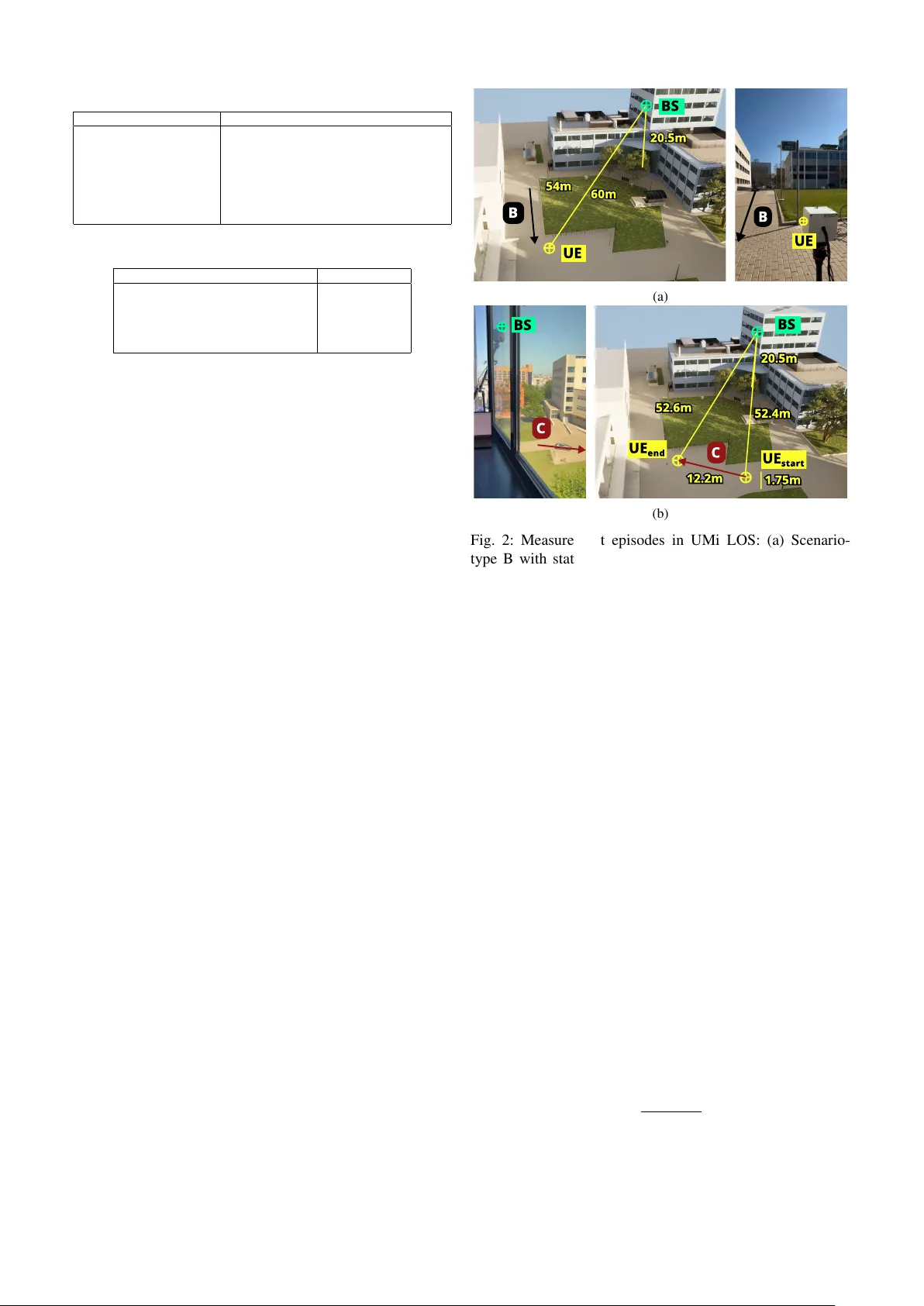
Deterministic Modeling of Dynamic ISA C Channels in RF Digital T win En vironments C ´ esar Montaner , Sa ´ ul Fenollosa, Andres Ortega, Hugo Beltr ´ an, Narcis Cardona iTEAM Resear ch Institute, Univer sitat P olit ` ecnica de V al ` encia cemoncar@iteam.upv .es, sjfenar g@upv .edu.es, alortort@iteam.upv .es, hbelsan@upv .edu.es, ncardona@iteam.upv .es Abstract —This paper intr oduces a methodology to calibrate Radio-Frequency Digital T wins (RF-DTs) for Integrated Sens- ing and Communication (ISA C) in dynamic wireless en viron- ments. The approach le verages high-resolution ray tracing in combination with wideband channel sounding to ensure consistency between simulated and measured pr opagation. The methodology is validated in urban scenarios featuring both mono-static and bi-static configurations, as well as moving user platforms and vehicles. Results show that the calibrated RF- DT r eproduces key propagation effects, including multipath evolution, dynamic scatterers, and Doppler -induced signatures, with close agreement to measurements. These findings confirm that accurate geometry , material modeling, antenna patterns, and diffuse scattering are essential for realistic high-frequency ISA C simulation. By bridging the gap between simulation and measurement, the pr oposed calibration framework provides a scalable tool for developing and evaluating ISA C algorithms in complex, time-varying envir onments envisioned for 6G. Index T erms —Digital T win, RF-DT , Dynamic ISA C, Channel Sounding, Ray-T racing, 6G Wireless Systems I . I N T RO D U C T I O N Integrated Sensing and Communication (ISAC) has emerged as a key paradigm for next-generation 6G systems, enabling wireless infrastructure to jointly support high-rate data transmission and en vironmental sensing [1]. Beyond spectrum reuse, ISA C pursues unified hardware and wa ve- form design to deliv er timely situational awareness for con- trol, automation, and safety-critical services. In this context, accurate channel models are essential, as they determine the fidelity of sensing/communication co-design and the reliability of data-dri ven algorithms. Ray-tracing (R T) and radio-frequency digital twins (RF-DTs) ha ve therefore gained traction for reproducing multipath propagation with high physical consistency [2]. Crucially , an RF-DT can generate and curate lar ge, labeled, and scenario-specific datasets under controlled interventions, thereby supplying the data needed to train and stress-test learning-based ISAC pipelines while supporting continual updates as en vironments ev olve. R T -based models have traditionally emphasized specular propagation in static scenes. This abstraction is insufficient for ISAC, which must learn from dynamic and variable en vironments where non-specular energy and motion carry discriminativ e information about objects and ev ents. In prac- tice, incorporating a diffuse–scattering abstraction is required to account for power that is not captured by a purely specular model at millimeter -wav e/sub-terahertz bands, while explicit mobility modeling is needed to reflect target- and platform-induced time v ariation. Experimental studies report that diffuse components can be a non-negligible share of receiv ed power in urban settings [3], motiv ating their inclu- sion alongside mobility within R T -based simulators [4]–[7]. Mode 1 Mode 3 Mode 4 Mode 5 Mode 2 Mono - sta tic sensing mode BS mono - sta tic sensing UE mono - sta tic sensing BSs bi- sta tic sensing UEs bi- sta tic sensing Do wnlink/uplink bi- sta tic sensing Bi- sta tic sensing mode (a) IS A C UE IS A C UE Mono - static channel Bi- static channel A B C IS A C BS IS A C SCA TTER ER (b) Fig. 1: Definition of ISA C Sensing Modes (a) and Channel Scenarios (b) Efficient implementations, such as directi ve/dif fuse scattering in Sionna R T , make this feasible at scale [8]. The present study adopts the ISA C mode/scenario tax- onomy of [9], observed in Fig. 1. Sensing modes are grouped into mono-static (transmitter and receiv er co- located; Modes 1–2) and bi-static (transmitter and re- ceiv er separated; Modes 3–5). Scenarios characterize mo- tion: (A) static transceivers and static channel elements, (B) static transceivers with moving elements, and (C) moving transceiv ers. Our focus is on realistic, dynamic operation, i.e., Scenarios B and C, with particular attention to User Equipment (UE) mono-static (Mode 2) and do wnlink/uplink Base Station (BS)–UE bi-static (Mode 5) sensing. This paper instantiates and validates a calibrated R T -based RF-DT for ISAC at 77–81 GHz tailored to Scenarios B/C and Modes 2/5 in Urban Microcell (UMi) settings. Giv en a geometrically consistent 3D representation of the scene and time-aligned trajectories for all moving entities, we: (i) perform synchronized wideband measurements with a chan- nel sounder over representative vehicle-mobility episodes; (ii) instantiate an R T simulation of the same episodes using the measured transceiv er states and tracked object kinemat- ics; and (iii) include material-parameterized directive/dif fuse scattering to account for non-specular paths. This enables a rigorous, phase-coherent comparison between simulation and ground-truth measurements ov er delay and Doppler, thereby assessing the extent to which a calibrated RF-DT can reproduce dynamic ISA C channels. The remainder of the paper is organized as follows. Sec- tion II details the methodology , cov ering the measurement campaign, scene geometry/kinematics acquisition, and R T configuration. Section III reports validation results against measurements across Modes 2/5 in Scenarios B/C. Sec- T ABLE I: Sensor Specifications Parameter V alue Center Frequency 79 GHz Bandwidth 4 GHz TX / RX Antennas 3 / 4 Peak Gain (per antenna) 10.5 dBi H / V Beamwidth (3 dB) ± 28 ◦ / ± 14 ◦ @ 78 GHz TX Po wer 12 dBm Noise Figure 14 dB (76–77 GHz), 15 dB (77–81 GHz) T ABLE II: Measurement Configuration Parameters Parameter V alue Ramp Duration ( T chirp ) 112.86 µ s Idle T ime ( T idle ) 13 µ s Chirp Slope ( S ) 35.44 MHz/ µ s I/Q Sampling Rate ( f s ) 18.75 MHz Max Range (Mono/Bi-static) ( R max ) 79.4 / 158.8 m tion IV discusses implications for ISA C system design and data-driv en sensing, and Section V concludes. I I . M E T H O D O L O G Y This section specifies a single, end-to-end procedure to instantiate and validate a calibrated R T -based RF-DT at 77–81 GHz for ISA C Modes 2/5 under dynamic UMi Scenarios B/C. The content is organized as follows: (i) measurement campaign and hardware; (ii) scenario design; (iii) scene/kinematics acquisition; (iv) R T configuration with directiv e/diffuse scattering; (v) dynamic channel representa- tion and delay–Doppler extraction; and (vi) alignment and comparison protocol consistent with the figures reported in the Results. The objectiv e is a like-for-lik e comparison between measured and simulated delay–Doppler signatures under realistic motion and non-specular propagation. A. Measur ement Campaign and Har dwar e A frequency-modulated continuous-wa ve (FMCW) sens- ing platform performs wideband E-band channel sounding using mutual-interference processing for bi-static character- ization [10], [11]. Each unit integrates three TX and four RX antennas; operation uses 4 GHz bandwidth centered at 79 GHz. Key radio specifications and experiment parameters are summarized in T ables I and II. The array layout af fords azimuthal cov erage suited to UMi links, while the 4 GHz bandwidth ensures fine range resolu- tion for separating nearby multipath components (MPCs) and enabling short-window Doppler estimation. B. Scenario Design (UMi LOS) Experiments were conducted on the Uni versitat Polit ` ecnica de V al ` encia campus (UMi, LOS). A BS node was placed at the fourth floor of Building 6D, illuminating the courtyard between buildings. T wo dynamic episodes were executed to realize Scenarios B/C and Modes 2/5: Configuration B (Scenario B; Modes 2/5). BS and UE are static; a Nissan Micra follows an approximately linear trajectory parallel to a facade. The BS points to the UE for a stable BS–UE link (Mode 5), and the UE boresight is oriented toward the vehicle path to enhance mono-static returns (Mode 2). Configuration C (Scenario C; Modes 2/5). The UE is roof- mounted on a mo ving KIA Xceed whose trajectory is roughly UE BS 20.5m 60m 54m B UE B (a) 20.5m 1.75m 12.2m 52.4m 52.6m UE e n d UE s t a r t B S C C B S (b) Fig. 2: Measurement episodes in UMi LOS: (a) Scenario- type B with static BS/UE and moving target; (b) Scenario- type C with moving UE platform. perpendicular to the BS boresight. Platform motion excites rich near-field interactions (e.g., bike racks, lamp posts) and strong far reflections from buildings. C. Scene and Kinematics Acquisition A metrically consistent 3 D model of the courtyard and sur - rounding facades is used to instantiate the RF-DT . Absolute transceiv er positions, boresights, and timing are logged per chirp. V ehicle trajectories are time-stamped and smoothed to enforce kinematic consistency , yielding time-aligned states for all moving entities required by the dynamic R T engine. D. RT Configuration with Dir ective/Diffuse Scattering Purely specular R T on lo w-polygon meshes underestimates power at mmW ave/sub-THz due to electromagnetic rough- ness; direct meshing at O ( λ/ 10) is infeasible at E-band [12]. Based on a three-le vel scattering abstraction, summarized in Fig. 3, a dif fuse scattering abstraction is therefore adopted in Sionna R T [8], splitting incident power into specular and diffuse components with conservation R 2 + S 2 = 1 , (1) where R is reflection reduction and S the scattering co- efficient. The diffuse lobe is directive around the specular direction, f s ( ˆ k s ) ∝ 1 + ˆ k T r ˆ k s 2 ! α s ( S ) , (2) with α s controlling lobe sharpness. Material-dependent S values, informed by empirical data [13], are assigned to typical urban surfaces (glass, concrete, metal, brick). The dS Tx Rx (a) ~λ/10 Tx Rx (b) Tx Rx (c) Fig. 3: Scattering abstraction: (a) physical scattering on rough surfaces; (b) micro-geometry discretization; (c) spec- ular reflection plus directiv e/diffuse lobe on macro facets. interaction order captures dominant specular plus first-order diffuse paths while av oiding path explosion [8]. Motion updates delays, angles, and Doppler at the chirp rate for Scenarios B/C. E. Dynamic Channel Representation and Delay–Doppler Extraction T o accurately model the time-varying characteristics of sensing channels in dynamic scenarios, the channel im- pulse response (CIR) is expressed as (3). Each multipath component n is characterized by a time-varying complex amplitude a n ( t ) , propagation delay τ n ( t ) , and a Doppler shift ν n ( t ) . This model is v alid both for real measurements and R T simulations, provided that the dynamic nature of the en vironment (e.g., moving scatterers or transcei vers) is properly captured. h ( t, τ ) = N X n =1 a n ( t ) δ ( τ − τ n ( t )) e j 2 πν n ( t ) t (3) T o obtain the Doppler-delay spectrum, H ( ν, τ ) , the Short- T ime Fourier T ransform (STFT) of the CIR is computed with respect to time over a window of duration T w , as defined in (4). H ( ν, τ ) = Z t 0 + T w t 0 h ( t, τ ) e − j 2 πν t dt (4) The key to simplifying the model is the assumption that in the short integration window T w , the parameters for each path are approximately constant, where a n ( t ) ≈ a n , τ n ( t ) ≈ τ n , and ν n ( t ) ≈ ν n . This leads to a locally stationary approximation of the channel impulse response. Applying these approximations, (5) is obtained by substituting (3) into (4). H ( ν, τ ) ≈ Z t 0 + T w t 0 N X n =1 a n δ ( τ − τ n ) e j 2 πν n t ! e − j 2 πν t dt ≈ N X n =1 Z t 0 + T w t 0 a n δ ( τ − τ n ) e j 2 πν n t e − j 2 πν t dt ≈ N X n =1 a n δ ( τ − τ n ) Z t 0 + T w t 0 e j 2 π ( ν n − ν ) t dt (5) The remaining integral is the Fourier transform of a complex exponential over a finite window . The magnitude of this integral is proportional to the sinc function: Z t 0 + T w t 0 e j 2 π ( ν n − ν ) t dt ∝ T w · sinc (( ν n − ν ) T w ) (6) This leads to the final expression for the Doppler-delay spectrum (7), where e j ϕ n is a complex phase term resulting from the integration bounds. H ( ν, τ ) ≈ N X n =1 a n e j ϕ n | {z } Complex Amplitude · δ ( τ − τ n ) | {z } Path Delay Impulse · T w · sinc (( ν n − ν ) T w ) | {z } Doppler Profile (7) The structure of (7) explains the output of a dynamic sensor-based system, justifying the beha vior observed in real- world measurements: • Path Delay Impulse : The δ ( τ − τ n ) term ensures that each multipath component appears as a sharp peak at its specific propagation delay τ n . • Doppler Profile : The sinc (( ν n − ν ) T w ) term describes the shape of the component in the Doppler domain. The sinc function is maximized when ν = ν n , meaning that each component’ s energy is concentrated in a peak centered at its true Doppler shift ν n . Static objects do not produce a Doppler shift ( ν n = 0 Hz), resulting in a central peak at zero frequency in the Doppler spectrum. In contrast, moving objects induce non- zero Doppler shifts ( ν n = 0 ), which appear as distinct peaks offset from the center , directly indicating their relative veloc- ities. This behavior enables comparison between measured Doppler-delay spectra (via FFT) and R T -predicted Doppler shifts, facilitating phase-aw are validation of the RF Digital T win in dynamic ISAC scenarios. F . Alignment and Comparison Pr otocol Processing mirrors the pipeline used to produce the figures in the Results, so that measurements and simulations are treated identically . T emporal alignment is performed at the chirp lev el using hardware timestamps, and delay alignment follows the measured FMCW timing model, enabling direct comparison of CIR delays without additional phase calibra- tion. Doppler information is extracted from short sequences of N = 128 consecutive chirps, defining T w = N T chirp + T idle , (8) with T chirp and T idle as in T able II. W ithin each window , motion manifests as the phase ev olution e j 2 πν n t of (7). The same windowing and DFT parameters are applied to both datasets. On the simulation side, the R T engine provides path delays and powers synchronized to the chirp grid; Doppler shifts ν n are computed from instantaneous radial velocities of the corresponding rays and used to modulate each path across the N chirps, yielding delay–Doppler spectra consistent with (7). Comparisons are then performed on power–delay profiles over time and on delay–Doppler maps computed on matched windows, emphasizing agreement of dominant components in delay , the stability of the ν ≈ 0 ridge from static scatterers, and the location of peaks associated with moving elements in Configurations B/C. Figures report side- by-side measured and simulated outputs with identical axes, windowing, and color scales. (a) (b) Fig. 4: Scenario B: PDPs for mono-static (a) and bi-static (b). T op: measurement; bottom: simulation. I I I . R E S U LT S This section ev aluates the calibrated RF-DT against mea- surements across Scenarios B/C and Modes 2/5. Results are organized by scenario, with emphasis on the agreement of power –delay structure, Doppler dynamics, and their rele- vance for ISA C operation. The analysis uses the aligned processing chain described in Section II, ensuring that mea- surements and simulations are directly comparable. A. Scenario B: Static T ransceivers with Moving V ehicle Scenario B considers static BS/UE nodes and a moving car . In the mono-static case (Fig. 4a), the approaching v ehicle creates a clear time-varying path that shifts in delay as the car mov es. This trajectory is consistently observed in both measurement and simulation, indicating that the calibrated RF-DT can correctly reproduce moving-tar get signatures. In the bi-static setup (Fig. 4b), distinct scatterers con- tribute: the LOS path, the vehicle, and reflections from building facades. Each appears as a separate MPC cluster , visible in both datasets. The R T faithfully reproduces their relativ e delays and temporal ev olution, which is critical for ISA C applications where distinguishing between static and dynamic reflectors underpins localization and tracking tasks. This confirms that the RF-DT can reproduce mixed en- vironments with both static and moving scatterers, ensur- ing that vehicle-induced signatures remain distinguishable against strong static multipath. B. Scenario C: Moving UE Platform Fig. 5a–5b report the Power Delay Profiles (PDPs) for Scenario C, where the UE moves on a vehicle platform. In the mono-static setup (Fig. 5a), both measurement and simu- lation exhibit multiple time-v arying MPCs. These trajectories arise from reflections of f nearby objects excited by the UE motion. The RF-DT not only reproduces the delays of these MPCs but also their temporal e volution, demonstrating that the inclusion of diffuse scattering and mobility-aw are ray updates is essential to match real-world dynamics. (a) (b) Fig. 5: Scenario C: PDPs for mono-static (a) and bi-static (b). T op: measurement; bottom: simulation. In the bi-static setup (Fig. 5b), the dominant path remains nearly constant in delay , consistent with the fixed BS–UE geometry . Secondary MPCs linked to en vironmental objects (e.g., facades, posts) appear at slightly varying delays, again well reproduced by the simulation. This validates the RF- DT’ s ability to capture the mixed static/dynamic structure typical of BS-to-UE sensing. These results highlight that the RF-DT accurately captures mobility-induced variations, not only in terms of path delays, but also in their temporal ev olution, which is essential for modeling realistic UE-side sensing scenarios. C. Doppler V alidation Beyond delay consistency , it is necessary to confirm whether the RF-DT captures the phase ev olution of multipath components within short observ ation windows, as modeled in (7). T o this end, Doppler-delay spectra is computed using N = 128 chirps in (8), corresponding to a temporal window of T w ≈ 16 ms. Fig. 6a–6b illustrate the results for Scenario B. In both measurement and simulation, a strong ridge centered at zero Doppler is visible, reflecting the contribution of static scat- terers such as walls and lamp posts. More importantly , both spectra show a distinct moving component at approximately 2 . 1 m/s and 62 ns delay , which corresponds to the trajectory of the vehicle. The ability of the RF-DT to reproduce this peak demonstrates that the simulator correctly maps object motions into Doppler shifts, as predicted by the theoretical model of (7). This capability is fundamental in ISA C settings, since Doppler diversity allows the system to discriminate moving tar gets from static clutter and to directly infer relati ve velocity . The close match between the simulated and measured Doppler-delay spectra indicates that the RF-DT preserves both amplitude and phase ev olution of dynamic multipath, making it suitable for velocity-a ware ISA C algorithm de vel- opment. −85 −80 −75 −70 −65 −60 Magnitude [dB] (a) −80 −75 −70 −65 −60 −55 −50 −45 −40 Magnitude [dB] (b) Fig. 6: Scenario B: Doppler-delay spectra from measurement (a) and simulation (b). I V . C O N C L U S I O N S This work has demonstrated that a calibrated RF-DT based on high-resolution ray tracing can accurately reproduce dy- namic ISA C channels in urban microcell en vironments. Com- parisons with measurements across ISA C Scenarios B and C, and under both mono-static and bi-static modes, showed that the simulator consistently captured multipath ev olution, delay variations from moving scatterers, and Doppler shifts. The close agreement between the simulated and measured power–delay profiles and Doppler–delay spectra confirms that the proposed framew ork provides a phase-aware and physically consistent representation of real-world propaga- tion. Beyond v alidation, these results highlight the conditions required for reliable RF-DT modeling: accurate 3D scene geometry , material-dependent scattering, realistic antenna patterns, and explicit handling of diffuse and dynamic contri- butions. By reproducing both static clutter and moving-tar get signatures, the RF-DT serves as a scalable surrogate for channel measurements, supporting the design of ISA C algo- rithms, benchmarking, and large-scale scenario exploration. In addition, the framework can be lev eraged to generate large and di verse datasets, enabling the training and e valuation of AI- and ML-based methods for sensing, communication, and joint processing. As such, the study bridges the gap between measurement-based characterization and simulation- based prototyping, facilitating robust sensing functionalities in future 6G networks. R E F E R E N C E S [1] S. Lu, F . Liu, Y . Li, K. Zhang, H. Huang, J. Zou, X. Li, Y . Dong, F . Dong, J. Zhu, Y . Xiong, W . Y uan, Y . Cui, and L. Hanzo, “Inte- grated sensing and communications: Recent advances and ten open challenges, ” IEEE Internet of Things Journal , vol. 11, no. 11, pp. 19 094–19 120, 2024. [2] J. Zhang, S. Xu, Z. Zhu, R. Y ang, C. Li, Y . Huang, and L. Y ang, “Digital-twin-enabled sensing channel estimation for 6g cell-free isac mimo system, ” in 2024 IEEE Wir eless Communications and Network- ing Confer ence (WCNC) , Dubai, UAE, 2024. [3] V . Degli-Esposti and H. Bertoni, “Evaluation of the role of diffuse scattering in urban microcellular propagation, ” in Gateway to 21st Century Communications V illage. VTC 1999-F all. IEEE VTS 50th V ehicular T echnology Conference (Cat. No.99CH36324) , vol. 3, 1999, pp. 1392–1396 vol.3. [4] J. Pascual-Garcia, M.-T . Martinez-Ingles, J.-M. M. Garcia-Pardo, J.-V . Rodriguez, and L. J. Ll ´ acer , “Using tuned diffuse scattering parameters in ray tracing channel modeling, ” in 2015 9th European Conference on Antennas and Pr opagation (EuCAP) , 2015, pp. 1–4. [5] S. Bakirtzis, T . Hashimoto, and C. D. Sarris, “Fdtd-based diffuse scattering and transmission models for ray tracing of millimeter- wav e communication systems, ” IEEE T ransactions on Antennas and Pr opagation , v ol. 69, no. 6, pp. 3389–3398, 2021. [6] Y . Y aman and P . Spasojevic, “ A ray-tracing intracluster model with diffuse scattering for mmwav e communications, ” IEEE Antennas and W ir eless Pr opagation Letters , vol. 20, no. 5, pp. 653–657, 2021. [7] F . Sheikh, D. Lessy , and T . Kaiser, “ A novel ray-tracing algorithm for non-specular diffuse scattered rays at terahertz frequencies, ” in 2018 F irst International W orkshop on Mobile T erahertz Systems (IWMTS) , 2018, pp. 1–6. [8] J. Hoydis, F . A. Aoudia, S. Cammerer, M. Nimier-Da vid, N. Binder, G. Marcus, and A. Keller , “Sionna rt: Differentiable ray tracing for radio propagation modeling, ” in 2023 IEEE Globecom W orkshops, GC Wkshps 2023 . Institute of Electrical and Electronics Engineers Inc., 2023, pp. 317–321. [9] W . Y ang, Y . Chen, Y . Zhang, Z. Y u, and M. Zhang, “Isac channel measurements and modeling methodology , ” in 2023 IEEE Globecom W orkshops (GC Wkshps) , 2023, pp. 1177–1181. [10] N. Cardona, J. S. Romero, W . Y ang, and J. Li, “Integrating the sensing and radio communications channel modelling from radar mutual interference, ” in ICASSP 2023 - 2023 IEEE International Confer ence on Acoustics, Speech and Signal Pr ocessing (ICASSP) , 2023, pp. 1–5. [11] A. Castilla, S. Fenollosa, M. Drozdowska, A. Lopez-Escudero, S. Mic ´ o-Rosa, and N. Cardona, “Novel approach to dual-channel estimation in integrated sensing and communications for 6g, ” in 2024 IEEE 35th International Symposium on P ersonal, Indoor and Mobile Radio Communications (PIMRC) , 2024, pp. 1–6. [12] A. T aflove, S. C. Hagness, and M. Piket-May , “Computational elec- tromagnetics: The finite-difference time-domain method, ” in The Elec- trical Engineering Handbook , W .-K. Chen, Ed. Burlington, MA: Elsevier Academic Press, 2004, ch. 9, pp. 629–670. [13] Y . Guo, T . Zhang, S. Sun, M. T ao, and R. Gao, “Measurement and analysis of scattering from building surfaces at millimeter-wav e frequency , ” in 2025 IEEE W ireless Communications and Networking Confer ence (WCNC) , 2025, pp. 1–6.
Original Paper
Loading high-quality paper...
Comments & Academic Discussion
Loading comments...
Leave a Comment