Performance Analysis of 5G RAN Slicing Deployment Options in Industry 4.0 Factories
This paper studies Radio Access Network (RAN) slicing strategies for 5G Industry~4.0 networks with ultra-reliable low-latency communication (uRLLC) requirements. We comparatively analyze four RAN slicing deployment options that differ in slice sharin…
Authors: Oscar Adamuz-Hinojosa, Abdelhilah Abdeselam, Pablo Muñoz
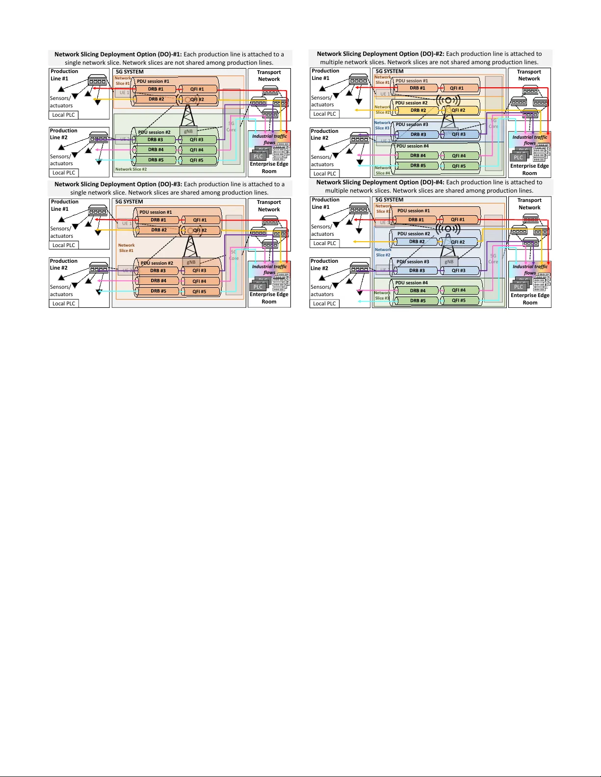
THIS IS AN A UTHOR-CREA TED POSTPRINT VERSION. Disclaimer: This work has been accepted for publication in the Joint Eur opean Conference on Networks and Communications & 6G Summit (EuCNC/6G Summit) , 2026. Copyright: © 2026 IEEE. Personal use of this material is permitted. Permission from IEEE must be obtained for all other uses, in an y current or future media, including reprinting/republishing this material for advertising or promotional purposes, creating new collectiv e works, for resale or redistribution to servers or lists, or reuse of an y copyrighted component of this work in other works. Performance Analysis of 5G RAN Slicing Deployment Options in Industry 4.0 F actories Oscar Adamuz-Hinojosa, Abdelhilah Abdeselam, Pablo Mu ˜ noz, Pablo Ameigeiras, Juan M. Lopez-Soler Department of Signal Theory , T elematics and Communications, Uni versity of Granada. Email: abdelhilah@correo.ugr .es, { oadamuz,pabloml,pameigeiras,juanma } @ugr .es Abstract —This paper studies Radio Access Network (RAN) slicing strategies for 5G Industry 4.0 netw orks with ultra- reliable low-latency communication (uRLLC) r equirements. W e comparatively analyze f our RAN slicing deployment options that differ in slice sharing and per-line or per -flow isolation. Unlike prior works that focus on management ar chitectures or resource allocation under a fixed slicing structure, this work addresses the design of RAN slicing deployment options in the presence of multiple production lines and heterogeneous industrial flows. An SNC-based analytical framework and a heuristic slice planner are used to evaluate these options in terms of per -flow delay guarantees and radio resour ce utilization. Results show that under resour ce scarcity only per -flow slicing prev ents delay violations by tightly matching resour ces to per -flow delay targets, while slice-sharing and hybrid deployments improv e aggregation efficiency at the cost of weaker protection f or the most delay- critical flows. Execution-time results confirm that the planner operates at Non-R T time scales, enabling its integration within O-RAN Non-RT RIC loops. Index T erms —5G, network slicing, Industry 4.0, uRLLC, stochastic network calculus, r esource allocation. I . I N T R O D U C T I O N Recent advances in 5th Generation (5G) are accelerating the adoption of wireless communications in Industry 4.0, enabling Industrial Internet of Things (IIoT), cyber-physical systems, and Real T ime (R T) automation [1]. Critical in- dustrial applications require deterministic ultra-Reliable Lo w Latency Communication (uRLLC) performance to ensure reliable operation of production lines, controllers, and sensors. Despite 5G uRLLC mechanisms such as flexible numerolo- gies, mini-slots, and grant-free access [2], strict latency and reliability guarantees remain challenging under wireless chan- nel variability and heterogeneous traffic. Under congestion, heavily loaded flows may impair others, and in industrial automation such timing violations directly affect production accuracy , including motion control, controller synchroniza- tion, and actuation. This highlights the need for performance isolation to protect delay-critical industrial processes under scarce radio resources. Network slicing has emerged as a key enabler of logical networks with tailored Quality of Service (QoS) require- ments [3]. By dedicating radio resources, slices can guarantee latency and reliability while isolating production-line traf fic, making them particularly relev ant for smart factories [4]. Howe ver , most existing works focus on architectures or re- source allocation algorithms, without systematically address- ing Radio Access Network (RAN) slicing-level deplo yment. In scenarios where multiple production lines demand hetero- geneous flows with di verse QoS requirements, the impact of RAN-lev el slicing decisions on isolation, delay guarantees, and resource efficienc y remains insufficiently understood. Literature Review . Prior studies on RAN slicing for indus- trial scenarios mainly focus on architectural frameworks, slice management, or resource allocation mechanisms. Rashid et al. [5] proposed slice descriptors to enhance reliability , while Perdig ˜ ao et al. [6] addressed automated slice management for factory en vironments. Other works in vestigated flexible slicing for heterogeneous traffic [7] or analyzed slicing ar- chitectures in edge federation and robotic systems [8], [9]. Complementary studies examined the limitations of current 5G releases for industrial traffic [10] and spectrum-level slicing strate gies with their trade-offs [11], while experimental platforms such as 5G-CLARITY demonstrated the feasibility of infrastructure-le vel slicing and multi-connecti vity in pri vate industrial networks [12]. Howe ver , they generally assume a predefined slicing structure and do not systematically charac- terize and assess alternati ve RAN slicing deployment options within a single factory , nor their impact on isolation, per-flo w delay guarantees, and radio resource utilization. Contributions . The above discussion exposes an open question: how should RAN slicing be instantiated in a factory to support heter ogeneous QoS requir ements acr oss multiple industrial flows? T o address this question, this paper makes the following contributions: C1 ) Identification and compar- ativ e analysis of multiple RAN slicing deployment options in industrial factories, clarifying their impact on isolation and per-flo w delay guarantees. C2 ) An Stochastic Network Calculus (SNC)-based analytical framew ork to derive per - flow delay bounds, adopted as a common basis for consistent comparison across deployment options. C3 ) A heuristic slice planner that allocates do wnlink radio resources to satisfy per- flow delay targets. Paper Organization . Section II introduces slicing options. Section III presents the traffic, resource, and channel models. Section IV -A details the SNC-based planner . Section V re- ports evaluation results. Section VI concludes the paper . I I . N E T W O R K S L I C I N G D E P L O Y M E N T O P T I O N S W e consider an industrial scenario within a single factory comprising multiple production lines served by a single 5G Base Station (BS). Each production line connects to the 5G UE 1 UE 2 5G C or e I nd us tri al tra f f i c f l ow s Ne tw o rk Sli c ing Deploy men t Op tio n ( DO) - #1 : E ach pr oduct i on l i ne i s a t t ached t o a si ng l e ne t w or k sl i ce . Ne t w or k sl i ce s ar e not sha r ed among pr oduct i on l i nes. 5G S Y S TEM gN B Q FI #1 PDU sessi on #1 Q FI #2 Netw o rk S l i ce #1 Q FI #3 PDU sessi on #2 Q FI #4 Q FI #5 T r an sp or t Ne t w or k Pr odu ct ion L ine # 1 Loc al P L C Pr odu ct ion L in e #2 Loc al P L C Sen so r s/ ac tu a t or s Sen so r s/ ac tu a t or s En t er pr is e E dg e R oom P LC P LC P LC Netw o rk S l i ce #2 U E 1 UE 2 5G C or e I nd us tri al tra f f i c f l ow s Ne tw o rk Sli c ing Deploy men t Op tio n ( DO) - #2 : E ach pr oduct i on l i ne i s a t t ached t o mult i pl e ne t w or k sl i ce s. Ne t w or k sl i ce s ar e not sha r ed among pr oduct i on l i nes. 5G S Y S TEM T r an sp or t Ne t w or k PDU sessi on #1 Netw o rk S l i ce #1 gNB Q FI #1 Netw o rk S l i ce #2 PDU sessi on #4 Q FI #4 QFI #5 Q FI #3 P DU se ssi on #3 Q FI #2 Pr odu ct ion L in e #1 Lo c al PL C Pr od u ct io n L in e # 2 Loc al P L C Sen so r s/ ac tu a t or s Sen so r s/ ac tu a t or s PDU sessi on #2 En t er pr is e E dg e R oom P LC P LC P LC Netw o rk S l i ce #3 Netw o rk S l i ce #4 U E 1 UE 2 5G C or e I nd us tri al tra f f i c f l ow s 5G S Y S TEM gNB Ne tw o rk Sli c ing Deploy men t Op tio n ( DO) - #3 : E ach pr oduct i on l i ne i s a t t ached t o a si ng l e ne t w or k sl i ce . Ne t w or k sl i ce s ar e sha r ed among pr oduct i on l i nes. Netw o rk S l i ce #1 Q FI #1 PDU sessi on #1 Q FI #2 Q FI #3 P DU se ssi on #2 Q FI #4 Q FI #5 Pr odu ct ion L in e #1 Loc al P L C Pr odu ct ion L in e #2 Loc al P L C T r an sp or t Ne t w or k En t er pr is e E dg e R oom P LC P LC P LC Sen so r s/ ac tu a t or s Sen so r s/ ac tu a t or s UE 1 UE 2 5G C or e I nd us tri al tra f f i c f l ow s Ne tw o rk Sli c ing Deploy men t Op tio n ( DO) - #4 : E ach pr oduct i on l i ne i s a t t ached t o mult i pl e ne t w or k sl i ce s. Ne t w or k sl i ce s ar e sha r ed among pr oduct i on l i nes. 5G S Y S TEM T r an sp or t Ne t w or k QFI #1 gN B PDU sessi on #1 Netw o rk S l i ce #1 PDU sessi on #4 Q FI #4 Q FI #5 Q FI #3 PDU sessi on #3 Q FI #2 Pr odu ct ion L in e #1 Loc al P L C Pr odu ct ion L in e #2 Loc al P L C Sen so r s/ ac tu a t or s Sen so r s/ ac tu a t or s P DU se ssi on #2 En t er pr is e E dg e R oom P LC P LC P LC Netw o rk S l i ce #2 Netw o rk S l i ce #3 Fig. 1. Network slicing deployment options in a 5G-based industrial network. W e assume production lines in a factory connect wirelessly to the 5G system, which then interfaces with the enterprise edge cloud through a transport network [13]. A Protocol Data Unit (PDU) session represents the logical connection established between an UE and the 5G core, Data Radio Bearers (DRBs) are radio-layer channels that transport the user traf fic, and QoS Flow Identifiers (QFIs) mark individual QoS flows within a PDU session, ensuring dif ferentiated treatment according to latency and reliability requirements. system through a single User Equipment (UE) that aggregates all traffic flows of that line. Prior studies identify multiple categories of industrial traffic, including control and synchronization flows, cyclic data exchanges, ev ent-triggered messages, robotic commu- nications, augmented-reality video, and configuration or di- agnostic traffic, each requiring differentiated performance guarantees [14]. While the number and types of flows per production line depend on the specific factory use case, our analysis does not assume any fixed traffic composition and instead considers a generic setting capable of accommodating heterogeneous traffic mixes. W e analyze four RAN slicing deplo yment options derived from two binary design dimensions: (i) whether slices are shar ed acr oss pr oduction lines , and (ii) whether slicing is performed at the pr oduction-line le vel . The resulting config- urations, obtained from the possible combinations of these di- mensions, are illustrated in Fig. 1. In practice, the appropriate deployment depends on traffic characteristics: heterogeneous and delay-critical flows require stronger isolation through finer-grained slicing, whereas more homogeneous or less stringent traffic can be efficiently supported through shared slices. Deployment Option (DO)-#1: One Slice per Produc- tion Line, No Inter -Line Sharing . Each production line is assigned a dedicated network slice that is not shared with other lines. Since each line is served by a single UE, the number of slices equals the number of production lines, and each UE establishes a single Protocol Data Unit (PDU) session carrying all flo ws of that line. Use case : This deployment provides inter -line isolation, ensuring that timing disturbances in one production line do not propagate to others. For example, a burst of ev ent-triggered alarms caused by a local fault remains confined within the slice of the affected line, preventing unintended degradation of control accuracy in neighboring production lines. Deployment Option (DO)-#2: Multiple Slices per Pro- duction Line, No Inter -Line Sharing . Each production line is attached to multiple network slices that are not shared with other lines, with each slice mapped to a distinct PDU session. While the most granular configuration assigns one slice per traffic flo w , a practical alternativ e groups flows by traffic category (e.g., cyclic control, video, best-effort, or diagnostics). Use case : W ithin a production line, deterministic closed-loop motion control can be isolated in a dedicated slice, while visual inspection or monitoring traffic is confined to another, prev enting delay inflation due to heterogeneous traffic and preserving the timing determinism required for accurate motion control. Deployment Option (DO)-#3: One Slice per Pr oduction Line, Shared across Pr oduction Lines . Each production line is associated with a single network slice, which may be shared with other lines. When multiple production lines share the same slice, the slice supports one PDU session per UE, resulting in multiple sessions anchored at the corresponding UEs. For instance, in Fig. 1, Production Lines #1 and #2 share a single slice comprising two PDU sessions, one per line. Use case : When several production lines generate homogeneous and non-critical traffic, slice sharing improves radio-resource efficienc y and scalability . Ho wever , this comes at the cost of weaker temporal isolation, which may degrade production accuracy if delay-critical traffic is inadv ertently aggregated. Deployment Option (DO)-#4: Multiple Slices per Pro- duction Line, with Shared Slices . Each production line is attached to multiple network slices, at least one of which is shared with other lines. Shared slices support one PDU session per UE, while the remaining slices remain dedicated to individual production lines. Use case : In hybrid deploy- ments, high-bandwidth video streams from inspection stations across multiple lines can be aggregated into a shared slice, whereas deterministic motion-control flows of robotic arms are confined to dedicated slices, preserving control precision while improving o verall radio-resource efficienc y . I I I . S Y S T E M M O D E L Let U denote the set of UEs, where each u ∈ U represents a production line. Each UE demands multiple traffic flows F , with each flo w f ∈ F characterized by a delay bound W f and a violation probability ε f , i.e., P [ w > W f ] ≤ ε f , where w denotes the radio-interface transmission delay . The subset F u ⊆ F collects the flows associated with UE u . The BS implements one of the slicing deployment options in Section II. The set of slices is denoted by S , and F s ⊆ F denotes the flows served by slice s ∈ S . Only latency and reliability constrained industrial traffic is considered. A. T raf fic Model Each flow f ∈ F is modeled as a Poisson packet arriv al process with average rate λ f . Packet sizes are denoted by d f ,i , where i ∈ N pkt f index es the set of possible sizes, and occur with probability p pkt f ,i , with P i ∈N pkt f p pkt f ,i = 1 . Flows aggregate packets with similar delay requirements and identical source–destination pairs, potentially originating from different applications or ev ents. The Poisson assumption is justified by traffic aggregation: although individual sources may follo w arbitrary distrib utions, the superposition of mul- tiple independent sources conv erges to a Poisson process according to the Palm–Khintchine theorem. B. Radio Resour ce Model Let N RB cell denote the total number of av ailable Resource Blocks (RBs) in the cell. The BS assigns N RB s RBs to each slice s ∈ S , subject to P s ∈S N RB s ≤ N RB cell . W ithin slice s , resources are distrib uted among its flo ws, with N RB f denoting the RB allocation of flow f ∈ F s , such that N RB s = P f ∈F s N RB f . For slices serving multiple flo ws, a Round Robin split is assumed without loss of generality , i.e., N RB f = N RB s / |F s | . Since the focus is on long-term delay guarantees, this static per-flo w allocation is adopted to simplify the analysis while preserving predictability and enabling delay-bound ev aluation. C. Channel Model The signal receiv ed by UE u on RB n is y u,n = q P tx u,n P pl u,n ˜ h u,n s u,n + n 0 , where s u,n has po wer P tx u,n , P pl u,n denotes the path loss, ˜ h u,n = h u,n e j v u,n models f ast fading, and n 0 is A WGN. The instantaneous Signal-to-Noise Ratio (SNR) at UE u on RB n is γ u,n = ¯ γ u,n | h u,n | 2 , with av erage ¯ γ u,n = P tx u,n P pl u,n / N 0 , where N 0 is the noise power . Since production lines are deplo yed at fix ed locations within the factory , ¯ γ u,n is assumed time-inv ariant. Moreover , the industrial cell operates on a carrier frequenc y different from neighboring public networks, so inter-cell interference in downlink is neglected. As the BS serves the factory from a single location and line-of-sight cannot be guaranteed due to machinery and metallic obstructions, fast fading is modeled as Rayleigh. Under this assumption, the instantaneous SNR follows an exponential distribution with Probability Density Function (PDF) f γ u ( γ ) = 1 ¯ γ u exp( − γ / ¯ γ u ) , which no longer depends on the RB index. Accordingly , the probability that UE u employs Modulation and Coding Scheme (MCS) m ∈ M is p u,m = R γ max m γ min m 1 ¯ γ u exp( − γ / ¯ γ u ) dγ , where M denotes the set of av ailable MCS lev els, each selected over its corresponding SNR range [ γ min m , γ max m ) . I V . N E T W O R K S L I C E P L A N N E R A. P acket Delay Modeling via Stoc hastic Network Calculus W e use SNC to derive per-flo w packet delay bounds. Let A f ( τ , t ) and S f ( τ , t ) denote the cumulative arriv al and service processes over ( τ , t ] for flow f ∈ F . SNC models them via probabilistic en velopes, P [ A f ( τ , t ) > α f ( τ , t )] ≤ ε A f and P [ S f ( τ , t ) < β f ( τ , t )] ≤ ε S f , where α f ( τ , t ) and β f ( τ , t ) are the arriv al and service en velopes, and ε A f and ε S f denote ov erflow and deficit probabilities. These en velopes are obtained from the statistical characterization of the underlying arriv al and service processes and capture traffic variability and wireless-service fluctuations, including packet-size randomness, traf fic intensity , and variations in the effecti ve RAN service rate. This probabilistic frame work enables robust delay provisioning under a tar get violation probability . The delay bound W f is giv en by the maximum horizontal de viation between α f ( τ , t ) and β f ( τ , t ) , assuming that the long-term service rate exceeds the arri val rate. Further details on SNC fundamentals can be found in [15], [16]. SNC Methodology . The estimation of the delay bound W f using SNC follows three main steps [15], [16]. 1) Moment Generating Functions (MGFs): The arri val and service processes A f ( τ , t ) and S f ( τ , t ) of each flow f ∈ F are first characterized by their MGFs. F or a random variable X , the MGF is defined as M X ( θ ) = E [ e θX ] , where θ > 0 is a tuneable parameter . 2) Exponential bounds: By applying Chernof f ’ s inequality , the cumulati ve arri val and service processes are respecti vely upper- and lower -bounded by affine en velopes α f ( τ , t ) and β f ( τ , t ) , parameterized by ( ρ A f , σ A f ) and ( ρ S f , σ S f ) . These parameters are obtained by fitting the corresponding MGFs to exponential bounds. 3) Delay bound derivation: Once the en velopes are defined, the delay bound W f is gi ven by the maximum horizontal deviation between α f and β f . In practice, it can be ex- pressed as W f = ( b A f + b S f ) / ( ρ S f − δ ) , where b A f = σ A f − ln( ε A f ) + ln(1 − exp( − θ δ )) /θ and b S f = σ S f − ln( ε S f ) + ln(1 − exp( − θ δ )) /θ are burst terms, and δ > 0 is a tuneable parameter . The stability condition ρ S f − δ > ρ A f + δ must hold, and ( θ , δ ) are optimized to minimize W f under the target violation probability ε f = ε A f + ε S f . In the following, we summarize the computation of the arriv al and service processes and the resulting delay bound, which are minor adaptations of v alidated SNC formula- tions [17], [18] and enable a consistent comparison across RAN slicing deployment options. Arrival Process f or a T raffic Flo w . Packet arriv als follo w a Poisson process with rate λ f , while packet sizes take discrete v alues { d f ,i } with Probability Mass Function (PMF) p pkt f ,i . Over the interval ( τ , t ] , the accumulated arriv als form a compound Poisson process with MGF M A f ( θ ) = exp λ f ( t − τ ) [ M L f ( θ ) − 1] , (1) where M L f ( θ ) = P i ∈N pkt f p pkt f ,i exp( θ d f ,i ) . This expression captures the variability induced by both random arrivals and packet-size fluctuations. The resulting af fine arri val en velope α f ( τ , t ) is characterized by ρ A f ( θ ) = λ f [ M L f ( θ ) − 1] /θ , σ A f ( θ ) = 0 . (2) Service Process for a T raffic Flow . In each Transmis- sion T ime Interval (TTI), the BS allocates N RB f RBs to flow f ∈ F . The number of bits served per RB equals N SC ∆ f t slot η , where N SC is the number of subcarriers per RB, ∆ f is the subcarrier spacing, t slot is the slot duration, and η is the spectral efficienc y selected by MCS adaptation. Let p f ,m = P { η = η m } denote the probability of using MCS m ∈ M , induced by the per-RB SNR distrib ution; since each flow f is associated with a specific UE u , p f ,m = p u,m if f belongs to u . The corresponding negati ve MGF of the per-RB service is M η ( − θ ) = P m ∈M p f ,m exp( − θ N SC ∆ f t slot η m ) , where ev aluation at − θ is standard in the e xponential domain of the service en velope. Assuming independence across RBs and TTIs, the cumulativ e service process S f ( τ , t ] has ne gativ e MGF M S f ( − θ ) = exp ln M C f ( − θ ) t − τ t slot , (3) with M C f ( − θ ) = P m ∈M p f ,m exp( − θ N SC ∆ f t slot η m ) N RB f , yielding ρ S f ( θ ) = − ln M C f ( − θ ) / ( θ t slot ) and σ S f ( θ ) = 0 . This formulation captures the variability of the wireless service across TTIs and allocated RBs due to random MCS selection induced by channel fading. Delay Bound for a T raffic Flow . The violation budget is ev enly split between arri val and service en velopes, i.e., ε A f = ε S f = ε f / 2 . Under this split and the en velope construction described abov e, the per-flo w delay bound is W f ( θ , δ ) = − 2 [ ln( ε f / 2)+ln ( 1 − e − θδ )] θ ( ρ S f ( θ ) − δ ) . The parameters ( θ , δ ) are obtained by solving min θ> 0 , δ> 0 W f ( θ , δ ) s.t. ρ S f ( θ ) − δ > ρ A f ( θ ) + δ, (4) which enforces the stability condition required for a finite delay bound. Problem (4) is non-conv ex in both the objective function and the feasible region, leading to multiple local minima and making exhausti ve search impractical. T o address this, we adapt the heuristic proposed in [18]. B. Pr oblem F ormulation For each flow f ∈ F , the delay bound W f is estimated using SNC (Section IV -A) and compared against its tar- get value W ob j f . W e define the normalized delay bound as W norm f = W f /W ob j f , and a flow is said to satisfy its QoS requirements if W norm f ≤ 1 . The RB allocation problem is formulated in Eq. (5). The optimization variables are the slice-level RB allocations { N RB s } s ∈S , which indirectly determine the per-flo w delay bounds. An auxiliary v ariable ζ captures the maximum nor- malized delay bound across all flows. The objecti ve is to find a slice-lev el allocation that maximizes ζ subject to per-flo w QoS and cell-capacity constraints: max { N RB s } , ζ ζ = max f ∈F W norm f s.t. ζ ≤ 1 , X s ∈S N RB s ≤ N RB cell . (5) The first constraint enforces compliance with the target delay bounds, while the second limits the total allocated RBs to the av ailable cell capacity . Maximizing ζ yields a margin-tight slice-lev el allocation, where radio resources are provisioned just sufficiently to satisfy all per-flo w delay requirements. C. Heuristic Solution The optimization problem is non-con vex and NP-hard, which precludes the use of e xact solution methods. T o address this, we propose a heuristic iterative algorithm structured into two phases, which progressiv ely improves the worst- case normalized delay while preserving feasibility through successiv e RB reallocations. Phase A. Delay Balancing. The algorithm starts from an equal RB allocation among slices. At each iteration, the flow with the highest normalized delay bound W norm f and the flow with the lowest W norm f belonging to a different slice are identified. These slices are denoted as the w orst and best slices, respecti vely . One RB is reallocated from the best slice to the worst slice, provided that the donor slice has more than one RB. After each reallocation, the per-flo w delay bounds W f , ∀ f ∈ F , are re-estimated using the SNC model. The reallocation is accepted only if it reduces the objecti ve v alue ζ in Eq. (5); otherwise, Phase A terminates. Since each iteration performs a single unitary RB reallocation and triggers a full recomputation of per-flo w delay bounds, and the number of admissible reallocations is upper -bounded by the total number of av ailable RBs, N RB cell , the computational complexity of Phase A is O ( N RB cell |F | ) . At con vergence, Phase A yields the minimum attainable worst-case normalized delay bound for the gi ven amount of radio resources. If the resulting allocation satisfies W norm f ≤ 1 for all flows, the algorithm proceeds to Phase B; otherwise, it terminates, as the av ailable spectrum is insufficient to meet all delay targets. Phase B. Resource Tightening. Phase B reduces the total number of allocated RBs while maintaining per-flo w delay feasibility . At each iteration, one RB is tentatively removed from each slice s with N RB s > 1 , and the resulting allocation is ev aluated by recomputing all per-flow delay bounds using the SNC model, assuming uniform intra-slice sharing. Among the feasible candidates, i.e., those for which the maximum normalized delay satisfies ζ ≤ 1 , the slice whose RB remo val yields the largest ζ is selected and the remov al is applied. This process is repeated until no further RB can be remov ed without violating delay constraints. Each iteration ev aluates up to |S | candidates, and at most N RB cell successful remov als are possible, resulting in a computational complexity of O ( N RB cell |S ||F | ) . Computational Complexity . Based on the abov e analysis, the worst-case computational complexity of the proposed heuristic is O ( N RB cell |S ||F | ) . In practice, the execution time is often lower , as either Phase A or Phase B may terminate early depending on the slicing configuration and the av ailable radio resources. D. W indow-Based Operation of the SNC-Based Slice Planner The proposed slice planner operates ov er a finite planning window , during which the statistical descriptors of traffic are assumed to be stationary . The ov erall operation time is partitioned into a sequence of planning windows W k = [ t k , t k + T w ) , k ≥ 0 , where T w denotes the windo w duration. W ithin each window W k , the planner computes a slice-level RB allocation based on a fixed set of traf fic statistics. For each traffic flow f ∈ F , the system behav- ior within window W k is characterized by the tuple ( λ ( k ) f , { p pkt , ( k ) f ,i } i ∈N pkt f , { p u,m } m ∈M ) , which determines the arriv al and service en velopes used by the SNC-based model to compute the per-flo w delay bound W ( k ) f . The stationarity assumption applies within a single planning window , while traffic statistics are allowed to evolv e across windows. In the considered industrial RAN scenario, UEs are static and associated with fixed production lines. As a result, the av erage SNR experienced by each UE , ¯ γ u , is assumed to remain constant o ver time. Consequently , the MCS selection PMF { p u,m } is also in variant across planning windows. In contrast, traf fic characteristics such as average arriv al rates or packet size distributions may change over time scales of minutes. These properties motiv ate a slice planning operation at a non-R T time scale. Accordingly , the proposed slice planner operates at the Non-R T RAN Intelligent Controller (RIC) within the Open Radio Access Network (O-RAN) architecture and may be implemented as an rApp [19], focusing on policy-dri ven, slice-lev el resource planning rather than R T radio resource adaptation. A window-based SNC-based control approach was previously introduced in [18] for near-R T per-user re- source allocation in public broadband networks without slic- ing. In contrast, the planner proposed in this paper adopts the SNC model dev eloped herein, operates at the Non-R T RIC, and extends the framework to slice-lev el resource planning tailored to industrial RAN scenarios. Under this windo w-based, Non-R T operation, the slice planning workflow proceeds as follo ws. Long-term traffic statistics are aggregated at the Non-R T RIC via the O1 interface, yielding estimates of λ ( k ) f and { p pkt , ( k ) f ,i } over W k . These statistics are used by an SNC-based slice planning rApp to compute per-flo w delay bounds and solve Eq. (5), obtaining the slice-level RB allocation { N RB , ( k ) s } s ∈S . The resulting allocation is translated into slice-lev el policies and con veyed to the near-R T RIC via the A1 interface. These policies are subsequently enforced through near-R T control actions delivered over the E2 interface to the Next generation NodeB (gNB), where they are applied by Distrib uted Unit (DU) MAC schedulers operating at the TTI scale. By iterating this procedure over successi ve planning win- dows, the slice planner periodically updates slice-lev el re- source allocations based on slowly varying traffic statistics, enabling long-term adaptation to changing operating condi- tions while preserving the SNC-based delay guarantees within each planning interval. V . P E R F O R M A N C E R E S U LT S A. Experimental Setup W e consider a single-cell industrial scenario with one centrally located BS serving three production lines placed at increasing distances, each demanding three downlink flows. This setup represents the minimum configuration required to illustrate all considered RAN slicing deployment options, including per-line isolation, slice sharing across production lines, and heterogeneous delay criticality among flows. The BS operates using 5G NR with subcarrier spacing ∆ f = 60 kHz and a carrier frequenc y of f c = 4 . 7 GHz. T wo band- width configurations are considered, corresponding to N RB cell ∈ { 65 , 135 } . The transmit power is set to P tx = 24 dBm and the thermal noise density to N 0 = − 174 dBm/Hz. Packets hav e a fixed size of L = 512 bits. Flow arri val rates, delay objecti ves, and distances to the BS are chosen to reflect representative industrial control traffic and are summarized in T able I. W e ev aluate five deployment options. In the baseline configuration (DO-#0), no slicing is applied and all flo ws are multiplexed within a single slice, S 1 = { f 1 , . . . , f 9 } . In DO-#1, one slice is assigned per production line, with S 1 = { f 1 , f 2 , f 3 } , S 2 = { f 4 , f 5 , f 6 } , and S 3 = { f 7 , f 8 , f 9 } . In DO-#2, one dedicated slice is assigned per flo w , i.e., S f = { f } for all f ∈ F . In DO-#3, flows associated with the first and second production lines, which e xhibit less restrictiv e delay bound requirements, are grouped into a shared slice T ABLE I P E R - U E T R A FFIC A N D Q O S R E QU I R E ME N T S . UE Flows λ f (pkt/s) W obj f (ms) Distance to BS (m) UE #1 f 1 , f 2 , f 3 2000, 3000, 1500 0.5, 0.5, 1.0 80 UE #2 f 4 , f 5 , f 6 5000, 6600, 4500 0.5, 0.5, 1.0 200 UE #3 f 7 , f 8 , f 9 9000, 11000, 8000 0.2, 0.2, 0.5 350 S 1 = { f 1 , . . . , f 6 } , while flows from the third production line, characterized by more stringent delay bound requirements, are assigned to a dedicated slice S 2 = { f 7 , f 8 , f 9 } . Finally , DO-#4 performs slicing based on delay bound requirements, grouping flo ws with W ob j f = 1 ms into S 1 = { f 3 , f 6 } , flo ws with W ob j f = 0 . 5 ms into S 2 = { f 1 , f 2 , f 4 , f 5 } , and assigning the most delay-critical flows to dedicated slices S 3 = { f 7 } , S 4 = { f 8 } , and S 5 = { f 9 } . The proposed slice planner has been implemented in a Python-based simulator . All experiments were executed on a machine equipped with 16 GB of RAM and a quad-core Intel Core i7-7700HQ processor running at 2.80 GHz. B. Comparison of Network Slicing Strate gies This section comparati vely ev aluates the considered RAN slicing deployment options under a common slice-planning framew ork, focusing on their impact on per-flo w delay guar - antees and radio resource utilization. T able II reports the resulting normalized delay bounds for all flows, T able III summarizes the slice-level RB allocations obtained after con vergence of the proposed planner , and Fig. 2 illustrates the trade-off between RB utilization and delay performance. Delay satisfaction. The impact of the slicing strategy on delay satisfaction is best analyzed by distinguishing between abundant and scarce bandwidth regimes. Under the 100 MHz configuration ( N RB cell = 135 ), all deployment options satisfy the per-flo w delay requirements, including the baseline with- out slicing (DO-#0). In this regime, flows f 7 and f 8 , which are characterized by the highest arri val rates and the most stringent delay objectiv es, consistently exhibit the largest normalized delay bounds across all deplo yment options, while still remaining below unity . Under radio resource scarcity ( N RB cell = 65 ), the influence of the slicing criterion becomes evident. The baseline configura- tion without slicing (DO-#0) exhibits se vere delay violations for flo ws f 7 and f 8 . Similar violations are observ ed in DO- #1, where isolation is enforced at the production-line level but flows with heterogeneous delay objecti ves still share the same slice. In particular, the violations originate in the slice associated with UE #3, which aggregates two highly delay- critical flows together with a third flow subject to a more relaxed delay bound, resulting in insufficient protection for the most stringent traf fic. DO-#2 provides the most robust delay performance under scarce bandwidth. By assigning one dedicated slice per flo w , the planner is able to closely match the allocated RBs to individual delay requirements, yielding the lowest worst-case normalized delay bounds and avoid- T ABLE II N O RM A L I ZE D D EL AY S W norm f F O R A L L FL O WS . Scenario ( N RB cell ) f 1 f 2 f 3 f 4 f 5 f 6 f 7 f 8 f 9 DO-#0 (65) 0.26 0.25 0.14 0.47 0.50 0.22 1.88 2.02 0.73 DO-#0 (135) 0.16 0.15 0.08 0.23 0.25 0.12 0.91 0.99 0.40 DO-#1 (65) 0.29 0.30 0.17 0.39 0.50 0.22 1.59 1.72 0.73 DO-#1 (135) 0.84 0.93 0.66 0.87 0.92 0.56 0.91 0.99 0.40 DO-#2 (65) 0.77 0.80 0.57 0.92 0.78 0.67 0.90 0.98 0.87 DO-#2 (135) 0.84 0.93 0.66 0.87 0.92 0.84 0.91 0.99 0.93 DO-#3 (65) 0.35 0.36 0.17 0.69 0.78 0.35 1.03 1.05 0.43 DO-#3 (135) 0.46 0.52 0.23 0.87 0.92 0.56 0.91 0.99 0.40 DO-#4 (65) 0.54 0.80 0.17 1.39 1.05 0.27 0.80 0.87 0.31 DO-#4 (135) 0.46 0.52 0.39 0.87 0.92 0.84 0.91 0.99 0.93 T ABLE III A L LO C A T E D R B S P E R S L I CE A F T ER A L GO R I T HM E X E CU T I O N . DO-#1 DO-#3 Slice 50 MHz 100 MHz Slice 50 MHz 100 MHz S1 { f 1 , f 2 , f 3 } 20 8 S1 { f 1 , . . . , f 6 } 33 29 S2 { f 4 , f 5 , f 6 } 22 14 S2 { f 7 , f 8 , f 9 } 32 41 S3 { f 7 , f 8 , f 9 } 23 41 T otal Allocated RBs 65 63 T otal Allocated RBs 65 70 DO-#2 DO-#4 Slice 50 MHz 100 MHz Slice 50 MHz 100 MHz S1 { f 1 } 3 3 S1 { f 3 , f 6 } 12 6 S2 { f 2 } 3 3 S2 { f 1 , f 2 , f 4 , f 5 } 14 20 S3 { f 3 } 2 2 S3 { f 7 } 13 14 S4 { f 4 } 4 5 S4 { f 8 } 13 14 S5 { f 5 } 5 5 S5 { f 9 } 13 7 S6 { f 6 } 3 3 S7 { f 7 } 12 14 S8 { f 8 } 12 14 S9 { f 9 } 6 7 T otal Allocated RBs 50 56 T otal Allocated RBs 65 61 ing violations across all flows. Slice-sharing configurations exhibit a dif ferentiated behavior . In DO-#3, delay violations persist for flows f 7 and f 8 ; howe ver , the corresponding normalized delay bounds remain close to unity , indicating that grouping flows according to relative delay criticality partially alleviates the impact of resource scarcity . In DO-#4, violations also occur under limited bandwidth, but they no longer affect the most delay-critical flows. Instead, the violations shift tow ards flows with intermediate delay objectives, reflecting the prioritization of stringent traffic within the slice-le vel resource allocation. Slice-level RB allocation. The slice-lev el RB allocations reported in T able III provide additional insight into how the different slicing strategies react to resource av ailability . Under spectrum scarcity ( N RB cell = 65 ), all deployment options except DO-#2 allocate the full available RBs. This indicates that, for these configurations, meeting the delay constraints requires exhausting the entire spectrum budget. In contrast, DO-#2 is able to reduce the total allocated resources to 50 RBs, indicating that per-flow slicing enables a tighter matching between allocated radio resources and indi vidual delay-bound constraints. When the av ailable bandwidth increases to N RB cell = 135 , the planner reduces the total number of allocated RBs in DO -#0 DO -#1 DO -#2 DO -#3 DO -#4 0.0 0.5 1.0 S l i c e R B u t i l i z a t i o n U R B s D i s t r i b u t i o n o f S l i c e R B U t i l i z a t i o n ( B W = 5 0 M H z ) Slice S1 S2 S3 S4 S5 S6 S7 S8 S9 DO -#0 DO -#1 DO -#2 DO -#3 DO -#4 0.0 0.5 1.0 S l i c e R B u t i l i z a t i o n U R B s D i s t r i b u t i o n o f S l i c e R B U t i l i z a t i o n ( B W = 1 0 0 M H z ) 0.0 0.1 0.2 0.3 0.4 0.5 0.6 0.7 Mean p 95 ( U RB s ) 0.2 0.3 0.4 0.5 0.6 0.7 0.8 0.9 1.0 1 | | ∑ f W norm f Delay Bound vs. RB Utilization 50 MHz 100 MHz DO-#0 DO-#1 DO-#2 DO-#3 DO-#4 Fig. 2. Slice-lev el RB utilization and delay–utilization trade-off across deployment options. W e report, for each deployment option, the mean 95th percentile of slice utilization and the av erage normalized delay bound across flows. all deployment options, reflecting the increased flexibility introduced by a larger spectrum budget. DO-#2 consistently achiev es the lo west total RB allocation, confirming that per- flow slicing allows the planner to precisely tune the slice bud- gets and av oid over -provisioning. The remaining deployment options allocate a larger fraction of the av ailable resources, as their slice definitions aggre gate multiple flo ws and therefore require higher slice-le vel b udgets to accommodate heteroge- neous traffic demands. Resource utilization vs delay bound. Fig. 2 illustrates the slice-lev el RB utilization and its relationship with de- lay bounds. Specifically , it represents, for each deploy- ment option, the av erage over slices of the 95th percentile of the utilization distrib ution, i.e., 1 |S | P s ∈S p 95 U RB s ( t ) , against the average normalized delay bound across flows, 1 |F | P f ∈F W norm f . In this representation, desirable operating points are those where slices make effecti ve use of the RBs assigned by the planner while operating close to the target delay bound. Under this criterion, the dif ferent deployment options exhibit clearly differentiated behaviors. DO-#2 consistently achieves operat- ing points closest to this regime under both bandwidth config- urations, as per-flo w slicing allows the planner to finely match the allocated RBs to indi vidual delay requirements. DO-#4 follows, since its delay-aware slicing structure isolates the most delay-critical flows while permitting limited aggregation among flo ws with comparable delay objectiv es, preserving a good balance between utilization and delay tightness. In DO-#3, grouping multiple flows with heterogeneous traf fic and delay characteristics within the same slice reduces the planner’ s ability to simultaneously achieve high utilization and tight delay operation. This effect is more pronounced in DO-#1, where all flo ws within a production line share a slice regardless of their delay objectives. Finally , DO-#0 exhibits the least fa vorable beha vior , as multiplexing all flo ws into a single slice prev ents ef fectiv e dif ferentiation. C. Execution T ime Analysis W e ev aluate the execution time of the proposed network slice planner by explicitly distinguishing between the two considered bandwidth configurations, N RB cell ∈ { 65 , 135 } . T able IV summarizes the conv ergence behavior and execution time of our solution. T ABLE IV E X EC U T I ON T I ME O F T H E N E T WO R K S L I C E P L A N NE R . Deployment Option N RB cell Phase A Phase B T otal Iterations Execution time (ms) DO-#0 65 (135) 1 (1) 0 (10) 1 (11) 149.1 (919.4) DO-#1 65 (135) 3 (2) 0 (72) 3 (74) 487.2 (15949.9) DO-#2 65 (135) 11 (2) 15 (79) 26 (81) 10821.9 (54587.8) DO-#3 65 (135) 1 (2) 0 (65) 1 (67) 304.1 (11147.7) DO-#4 65 (135) 2 (2) 0 (74) 2 (76) 595.1 (28851.0) Low-bandwidth regime ( N RB cell = 65 ). Most deployment options con verge in well below 1 s, with execution times between approximately 150 and 600 ms for DO-#0, DO-#1, DO-#3, and DO-#4. In these cases, the limited RB budget significantly constrains the number of feasible slice-level RB reallocations, thereby reducing the size of the search space explored by the planner and enabling con ver gence after only a few iterations. The main exception is DO-#2, where per- flow slicing induces a lar ger number of iterations, leading to an execution time on the order of 10 s. High-bandwidth regime ( N RB cell = 135 ). All deployment options exhibit a clear increase in the number of iterations and ex ecution time. In DO-#0, the increase remains moderate, with con vergence reached in 11 iterations and just under 1 s. In this case, Phase A is trivial and the e xecution time is dom- inated by Phase B, which progressiv ely removes RBs from the single slice while preserving equal per-flow allocation, until the minimum RB budget satisfying all delay bounds is obtained. DO-#1 and DO-#3 require between 65 and 74 iterations and execution times on the order of 10 – 16 s, as slice sharing across multiple flo ws and production lines leads to a large number of Phase B tightening steps. Finally , fine- grained slicing strategies such as DO-#2 and DO-#4 yield the highest ex ecution times, reaching se veral tens of seconds, since the larger RB budget combined with per-flo w or near per-flo w slice definitions substantially increases the number of feasibility-preserving RB removals performed in Phase B. D. Scalability Analysis W e e valuate the scalability of the proposed solution under N RB cell = 135 RBs, focusing on DO-#2, which represents the most computationally demanding configuration. Fig. 3 reports the ex ecution time as a function of the total number of flows |F | for different numbers of production lines. Flows are equally distrib uted across production lines, and each flo w in- herits the average SNR associated with its corresponding line. Production lines are placed at different distances from the BS, while traf fic flo ws are defined using a cyclic assignment ov er a set of representative arriv al rates and delay requirements defined in T able I. For |F | ≤ 18 , the execution time increases with |F | for all considered numbers of production lines, ranging from a few tens of seconds up to approximately 260 s. This increase is primarily driven by the higher computational cost of individual iterations. As discussed in Section IV -C, each iteration in both Phase A and Phase B requires a full 6 9 12 15 18 24 30 N u m b e r o f f l o w s ( | | ) 0 50 100 150 200 250 Ex ecution time (s) (bars) 0 20 40 60 80 100 120 T otal number of iterations (lines) 1 pr oduction lines 2 pr oduction lines 3 pr oduction lines 5 pr oduction lines Fig. 3. Execution time of the network slice planner as a function of the number of flows |F | and production lines. recomputation of per-flo w SNC-based delay bounds, whose cost scales linearly with |F | (and with |S | in Phase B), leading to longer per-iteration execution times as the number of flows grows. Additionally , the total number of iterations required for con vergence decreases with |F | . As the same pool of N RB cell RBs is shared among a larger number of flows, the number of admissible RB reallocations or remov als becomes more limited, causing the heuristic to con verge in fewer iterations. Despite this faster con vergence, the increase in per-iteration cost dominates, resulting in higher overall execution times. For a fixed number of flows, configurations with a larger number of production lines generally exhibit lo wer ex ecution times. In these cases, the increased heterogeneity in av erage SNR across production lines reduces the feasible region, causing Phase B to terminate after fewer tightening iterations. The highest ex ecution times are observed for |F | = 24 , where the heuristic remains close to feasibility and both Phase A and Phase B are ex ecuted for a non-negligible number of iterations, leading to a peak ex ecution time close to 300 s. In contrast, when radio resources are clearly insufficient to further reduce the objecti ve function, infeasibility is detected early , Phase A terminates after very few iterations with ζ > 1 , and Phase B is skipped. This explains the markedly lower execution times observed for some configurations with |F | = 24 and for all cases with |F | = 30 . The execution times range from a few tens of seconds to sev eral hundreds of seconds. Giv en that av erage traffic statistics evolv e on time scales on the order of minutes, these results support the feasibility of window-based network slice planning at the Non-R T RIC in the O-RAN architecture. V I . C O N C L U S I O N S A N D F U T U R E W O R K S This paper ev aluated four RAN slicing deployment options for 5G-based Industry 4.0 using a common SNC-based slice planning framew ork. The results show that per-flow slicing (DO-#2) is the only deployment option that consistently meets uRLLC latency tar gets under limited spectrum a vailability , whereas per-line (DO-#1), shared (DO-#3), and hybrid (DO- #4) deployments trade isolation for improv ed aggregation effi- ciency . The execution-time and scalability analysis indicates that the proposed planner operates at Non-R T time scales, with execution times ranging from sub-second to several tens of seconds, supporting its practical use for window-based slice planning in industrial O-RAN deployments. Future work will extend the frame work tow ards joint radio and Time- Sensitiv e Networking (TSN)-aware traffic coordination to support tightly synchronized industrial automation systems. A C K N O W L E D G M E N T This work is part of grant PID2022-137329OB-C43 funded by MICIU/AEI/ 10.13039/501100011033 and by ERDF/EU. R E F E R E N C E S [1] M. W ollschlaeger , T . Sauter , and J. Jasperneite, “The Future of Indus- trial Communication: Automation Networks in the Era of the Internet of Things and Industry 4.0, ” IEEE Ind. Electr on. Mag. , vol. 11, no. 1, pp. 17–27, 2017. [2] T .-K. Le, U. Salim, and F . Kaltenberger, “An Overvie w of Physical Layer Design for Ultra-Reliable Lo w-Latency Communications in 3GPP Releases 15, 16, and 17, ” IEEE Access , vol. 9, pp. 433–444, 2021. [3] O. Adamuz-Hinojosa, P . Mu ˜ noz, P . Ameigeiras, and J. M. Lopez-Soler , “Potential-Game-Based 5G RAN Slice Planning for GBR Services, ” IEEE Access , vol. 11, pp. 4763–4780, 2023. [4] 5G-A CIA, “5G QoS for Industrial Automation, ” white paper, 5G Alliance for Connected Industries and Automation (5G-ACIA), Nov . 2021. [5] M. M. Rashid, M. Carmen Lucas-Esta ˜ n, M. Sepulcre, and J. Gozalvez, “5G RAN Slicing to Support Reliability in Industrial Applications, ” in IEEE ETF A , pp. 1–4, 2022. [6] A. Perdig ˜ ao, J. Quevedo, and R. L. Aguiar, “ Automating 5G net- work slice management for industrial applications, ” Comput. Commun. , vol. 229, p. 107991, 2025. [7] J. Zhang, Y . Zu, Y . Zhang, and B. Hou, “Dynamic RAN Slicing with Effecti ve Isolation under Imperfect CSI, ” in IEEE CCET , pp. 238–242, 2022. [8] T . T aleb, I. Afolabi, and M. Bagaa, “Orchestrating 5G Network Slices to Support Industrial Internet and to Shape Next-Generation Smart Factories, ” IEEE Netw . , vol. 33, no. 4, pp. 146–154, 2019. [9] S. S. Mhatre, K. Ramantas, R. Qiu, and C. V erikoukis, “Slicing enabled 5G experimentation platform for the Robotics vertical industry , ” in IEEE MeditCom , pp. 123–126, 2021. [10] M. C. Lucas-Esta ˜ n, J. Garc ´ ıa-Morales, and J. Gozalvez, “Latency- Sensitiv e 5G RAN Slicing for Deterministic Aperiodic Traffic in Smart Manufacturing, ” in IEEE FNWF , pp. 1–5, 2023. [11] P . Mu ˜ noz, O. Adamuz-Hinojosa, J. Nav arro-Ortiz, O. Sallent, and J. P ´ erez-Romero, “Radio Access Network Slicing Strategies at Spec- trum Planning Level in 5G and Beyond, ” IEEE Access , vol. 8, pp. 79604–79618, 2020. [12] T . Cogalan et al. , “5G-CLARITY : 5G-Advanced Priv ate Networks Integrating 5GNR, WiFi, and LiFi, ” IEEE Commun. Mag. , vol. 60, no. 2, pp. 73–79, 2022. [13] 5G-A CIA, “Integration of 5G with T ime-Sensitive Networking for Industrial Communications. ” White Paper , Feb. 2021. [14] O. Adamuz-Hinojosa, F . Delgado-Ferro, J. Navarro-Ortiz, P . Mu ˜ noz, and P . Ameigeiras, “Unleashing 5G Seamless Integration W ith TSN for Industry 5.0: Frame Forwarding and QoS Treatment, ” IEEE Open J. Commun. Soc. , vol. 6, pp. 4874–4884, 2025. [15] M. Fidler, “Survey of deterministic and stochastic service curve models in the network calculus, ” IEEE Commun. Surv . Tutor . , vol. 12, no. 1, pp. 59–86, 2010. [16] M. Fidler and A. Rizk, “A Guide to the Stochastic Network Calculus, ” IEEE Commun. Surveys T uts. , vol. 17, no. 1, pp. 92–105, 2015. [17] O. Adamuz-Hinojosa, V . Sciancalepore, P . Ameigeiras, J. M. Lopez- Soler , and X. Costa-P ´ erez, “A Stochastic Network Calculus (SNC)- Based Model for Planning B5G uRLLC RAN Slices, ” IEEE T rans. W ireless Commun. , vol. 2, no. 2, pp. 1250 – 1265, 2022. [18] O. Adamuz-Hinojosa, L. Zanzi, V . Sciancalepore, A. Garcia-Saavedra, and X. Costa-P ´ erez, “ORANUS: Latency-tailored Orchestration via Stochastic Network Calculus in 6G O-RAN, ” IEEE INFOCOM , 2024. [19] M. Polese, L. Bonati, S. D’Oro, S. Basagni, and T . Melodia, “Under- standing O-RAN: Architecture, Interf aces, Algorithms, Security , and Research Challenges, ” IEEE Commun. Surv . T utor . , pp. 1–1, 2023.
Original Paper
Loading high-quality paper...
Comments & Academic Discussion
Loading comments...
Leave a Comment