An Accurate and Fast Start-up Scheme for Power System Real-time Emergency Control
With the development of PMUs in power systems, the response-based real-time emergency control becomes a promising way to prevent power outages when power systems are subjected to large disturbances. The first step in the emergency control is to start…
Authors: Songhao Yang, Zhiguo Hao, Baohui Zhang
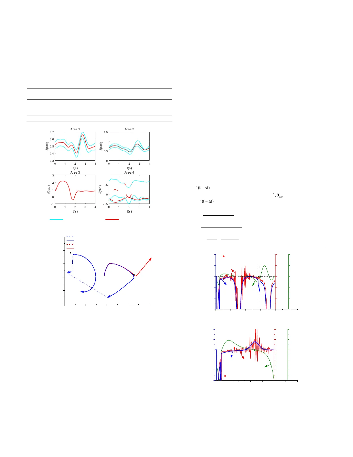
> REPLACE THIS LINE WI TH YOUR PAPER IDENTIFI CATION NUMBER (DOU BLE- CLICK HERE TO EDIT) < 1 Abstract — With the development of PMUs in power systems, the response-based real-time emergency control becomes a promising way to prevent power outages when power system s are subjected to large disturbances. The first step in the emergency control is to start up accurate ly and fast when n eeded. To this end, t his paper proposes a well-qualified start-up scheme for the power system real-time emergency control. T hree key technologies are proposed to ensure the effectiveness of t he scheme. They are an instability index, a Critical Machines (CMs) identification algorithm and a two-layer Single Machine Infinite Bus (SMIB) equivalence framework. The concave-convex area based instability index shows good accuracy and high r eliability, which is used to identify the transient instability of t he syste m. The CMs identification algorithm c an track the changes of CMs and form the pr oper SMIB system at each moment. The new two-layer S MIB equivalence framework, compared with conventional ones, can significantly reduce the communication burden a nd improve the computation efficiency. The simulations in tw o test power systems show that the scheme c an identify the transient instability accurately a nd fast to restore the system to stability after the emergency control. Besides, the proposed method is robust to measurement errors, which enhances its practicality. Index Terms — C on cave-convex area, CMs identifica tion , two - layer SMIB equivalence, transient stability , response-based emergency control I. I NTRODUCTIO N ORDEN power systems are operating near their desig ned stability limits due to economic reasons and op erational constraints [1] . When subjected to larg e disturbance s , these power system s suffer a h igh r isk of loss of synchronism and even power outage. In this situation , the r eal-time emerg ency control becomes vital to the power system . The primary step of such control is to identify the transient instability and start the control. Th e em ergency control should only be activated if the system is indeed d riving to instability . Otherwise, th e wrongly initiated emergen cy contro ls may deteriorate th e transient stability of th e system . I n addition , the emergency control should be started fast in ord er to guarantee the effect iveness of control measures. Thus, a start- up schem e that features accu rate and fast tr ansient instability detection is nec essarily req uired for the emerg ency control. Currently, the start-up schemes of the emergency control are either event-b ased or response-based. The event-based emergency control methods first evaluate the transien t stability of a series of pre-imagine d co ntingencies by Transient Stability Assessment (TSA) techniques , e.g. , the Extend ed Equal Area Criterion ( EEAC) [2], Sin gle Machine Eq uivalent (SIME) [3] , stability region theory [4] and relative transient e nergy function [5]. Then they design p roper contr ol actio ns for unstable cases and finally der ive a decision table [6, 7] . Once a pre-im ag in ed contingen cy occurs, the emergency control will be initiated immediately, and the corr esponding control actions will be taken [8] . Desp ite the fast response spee d, the se even t-based emergen cy control schemes h ave restricted accuracy due to their depen dence on offline simu lations when they are applied in the real-time emergen cy co ntrol . Besides, these method s can only han dle the pre- imagined contingencies , but fail to deal with the un expected ones . The response-based real-time emergency control, by contrast, aims at assessing whether the contingency that has already occurred is driving the system to instability . With the developm ent of PMUs in th e p ower sy stem, the se response- based methods are attracting mo re and more attention. These methods can be classified into three categories:1) p redicted response base method s , 2) machine learni ng based methods and 3) instability ch aracteristic based methods. The predicted response based start -up schemes predict the future transient respo nse of the p ower system by m odel-free methods such as the curve f itti ng technique [9] and then d etect the instability in real time. Despite being simple and requiring little information , these schemes hav e unstable accu racy because the p rediction accuracy is sen sitive to the num ber of data points , the sampling f requency and the order of prediction model [10, 1 1]. The inaccurate pred iction will lead to the malfunction of the real-time emergen cy control. Although the machine learning methods are heuristic, they are widely u sed in emergency control bec ause of their fast response speed . In th is kind of m ethods, a series of classifiers are trained offline through machine learning techniques such as decision tree [12, 13], artificial neural network [1, 14-16] and support vector machine methods [17-20]. Then the classifiers are ap plied in real time to identify the transient instability. The accuracy of these meth ods is promising when classifiers are sufficient ly train ed. However, offline training is a time- consuming work bec ause it needs to adapt to the var ious sy stem operati ng conditions and numero us possible disturban ces . Moreover, the classifiers become unreliable if the practical system shows different dynamics from the offline training data . An Accurate and Fast Start-up Scheme for Power System Real-time Emer gency Control Songhao Yang, s tudent member , IEEE , Z higuo Hao, Membe r, IEEE , Baohui Zh ang, Fellow , IEEE , Masahide Hojo, Memb er, IEEE M Songhao Yang, Zh iguo Ha o and Baohui Zha ng are with Scho ol of Electrical En gineering, Xi’an J iaotong U niversity, Xi’an, China. (email: songhaoyan g@stu.xjtu.edu.cn; zhgha o@mail.xjtu.edu .cn ; bhzhang@mail.x jtu.edu.cn). Masahide Hojo a r e w i th Department of Ele ctrical and Electronic Engineering, T okushima Uni versity, Tokushima, Japan (email: hojo@ee.t okushima-u.ac.jp) > REPLACE THIS LINE WI TH YOUR PAPER IDENTIFI CATION NUMBER (DOU BLE- CLICK HERE TO EDIT) < 2 For t he instability characteristic based method s, specific instability criter ia de duced from th e mathematical or physical analysis are involved. They seem to be more reliable than those heuristic methods because of their physical theoretical foundation . T he in stability cr iteria ar e mo stly calcu lated bas ed on the measured physical variables such as the state variables of the buses an d g enerators. In [ 21], the Lyapun ov Ex ponent s ( LEs ) of generator pairs wer e ap plied to identify the transient stability in real time . However, it takes secon ds to correctly identify the instability, which is too late for the real-time emergency control. A post-d isturbance bus v oltage magnitude- based stability prediction method was proposed in [ 22] . Although the method is f ast and straightforward , it needs to determine the stability boundar y in advance by off line simulation, wher e the parameter and model un certainties may decrease the accu racy. T he emergen cy SIME metho ds in [ 3] and [23] get rid of the dependence on models by determining the p arameters o f the equ ivalent Singe Mach ine Inf inite Bus (SMIB) system with P MU d ata. Ho wever, th e accuracy of the parameter s identification cannot be gu aranteed in th e practical power system. The graphic al characteristic of the phase trajectory was applied to the transient instability detection of the SMIB system in [24], which was describ ed as: ’ a stable trajectory is always concav e with respect to the post -fault Stable Equilibrium Point ( SEP) while an unstabl e trajectory is convex with respec t to the post- fault SEP immediately or a short ti me after the fault -clearing time ’ . T he instability feature was mathematically demon strated in [25] and was further extended to the multi-machine p ower system by a SMIB equivalence in [26]. The instability characteristic of the p hase trajectory is simp le and easy to identify, which is prom ising in the r eal -time TSA . However, several p roblems need to b e addressed bef ore the characteristic is used to start real-time emergen cy control. Firstly, wh en using the discrete PMU data for the instability index calculatio n , the ex isting meth ods in [ 25, 26] have the se vere p roblem of noise due to multiple differential operations, which m ay start the em ergency control incorrectly. Secondly , the SMIB equ ivalence is required to evaluate th e transient stability of the multi-machine power system. However, the time-chan ging critical machines (CMs) increase the difficulty of obtain ing an accur ate SMIB system. Th irdly, in the conventional SMIB eq uivalence methods , all gen erator data needs to be directly upload ed to the glob al control center. However, this way of pro cessing data is no t allowed in a practical po wer system due to d ata privacy and limitations o f existing h ierarchical con trol framework . Moreo ver , when applied to a large-scale power system, the conven tional equivalence methods ha ve the p roblems of heavy communication burden and long compu tation time [ 27, 28] . The transmission of massive data under in sufficient bandwidth will cause communicatio n d elay and data drop out , which may reduce the accuracy of the start-u p scheme. And the long processing time of massive data in the global control ce nter will delay the start -up of the emergency control. In this paper, an accurate and fast start- up scheme is pr oposed for power system real-time emergen cy control. T he start-up scheme is continuously ex ecuted with th e updated measuremen t data from PMUs. If the power system is identified as u nstable, the emergency control will be initiated immediately to prevent the system from collapse. The accuracy of the scheme is guaranteed by a reliable insta bility index a nd a real-time CMs identification alg orithm. The instab ility ind ex featur es less information requ ired, smaller compu tation amount and high er noise tolerance. The CMs identification algorithm can track t he change s of CMs d uring the tr ansient process to form the correct SIMB system at each moment . The real-time operation of t he start-up scheme ben efits from a novel two -layer SMIB equivalence framework which enables to reduce the communication burden and improve the computation e fficiency of massive data. The r est of p aper is organized as follows: Section II introduces the co ntributions of the work . Section III presents the outline of the start-up schem e for real -time emergency control. Simulations in section I V ver ify the effectiveness of th e p roposed sta rt -up sch eme and section V gives the con clusion. II. C ON TRIBUTIONS To start the real-time emergency control accurately and fast, we propose a reliab le instab ility ind ex, a fast two-layer SMIB equivalence framework and a real-time critical machi nes identification alg orithm in th is paper. A. The conca ve-convex area-ba sed instability index For a SMIB power sy stem, the conv ex-concavity o f the phase trajectory is p roved to be related to the system’s transi ent stability [24 -26] . To apply th is relation ship to real-time emergency control of the power system, we develop a novel instability index based on th e concept of the concave-convex area on th e phase plane . Mathematically, the curve () y f x = is co nvex if it satisfies ( ) 0 fx . For the phase trajecto ries on the ph ase plane that is composed of the generator ’s power an gle and angular speed deviation , the con cave-convexity ind ex of the phase trajectory can be defined as 2 2 d l d = (1). The continuous curve composed by t he ph ase point s that satisfy l =0 is called infle ct ion curve. It naturally div ides the phase plane into two areas: the concave area ( 0) l • and the convex area 0) l • ( . T he lo cation o f th e co ncave-convex areas on the phase plane is given in Fig. 1 which also shows the relationship between p hase trajectories and the con cave-convex areas . In Fig. 1 , the trajec tories of stable cases in wh ich the fa ult duration is short er than the C ritical Clearance Tim e (CCT) ( t c1 < t c2 < CCT ) always stay in the concave area whereas the trajectories of u nstable cases in which the fault is cleared later than the CCT ( CCT < t c3 < t c4 ) enter the convex ar ea inev itably. As a ‘black hole’ on the phase plane, the convex area is the no- return- area for phase trajectories, which indicates the tra nsient instability of th e power system . Thus, transient in stability of t he system can be id entifi ed by dete cting whether the phase trajectory en ters the convex area. > REPLACE THIS LINE WI TH YOUR PAPER IDENTIFI CATION NUMBER (DOU BLE- CLICK HERE TO EDIT) < 3 concave area -0.02 0.00 0.02 t e t c4 t c3 t c2 u Stable trajectory Unstable trajectory s Speed Deviation (p.u.) Angle (rad) convex area o s Inflexion curve t c1 Fig. 1 Phase traje ctories and the conc ave-convex areas o n the phase p lane According to the definition of the convex area, the phase trajectories in co nvex area satisfy (2 ). 2 2 0 1 0 0 0 0, d dk d dk l d d dt dt • • • • (2) where k is the slope of phase trajectory d k d = and 00 2 f = . 0 f is the system frequ ency, 50Hz or 60Hz. The rotor motion equations of the SMIB system in (3) is used to avoid the mu lti-order derivation operations in (2). 0 0 0 ; me M P P D P D •• = = − − = − , (3) where em PP , and P are s eparately gener ator’s electrical power, mechanical po wer, and power difference . Parameters D is the damping facto r, and M is inertia con stant. Th us, the slope k can be written in the form of (4). 0 0 PD d dt k dt d M − = • = (4) Since that th e measurement data fr om PMUs is discrete, (5) gives a differ ential form of the new in stability criterion in (2). 0 ( ) ( ) 1 ( ) ( ) ( ) 0 ( ) ( ) k t k t t P t P t t t tM t t t − − − = − − (5) A simpler form is deduced in (6 ) by omitting the constant terms in ( 5). ( ) ( ) ( ) 0 ( ) ( ) P t P t t ct t t t − = − − (6) It can b e inferred from (6) that the calculation of the new instability in dex only require th e data of the current moment t and last moment tt − , an d all required generator information, P and , can be ob tained from PMUs . Also, it should be noted in Fig. 1 that the instability detection time, e t , namely the moment phase trajectory enters the c onvex area, is earlier than the moment that the angle exceeds the angle of Unstab le Eq uilibrium Point(UEP), u . According to [29] , if no control measures are taken, the system will in evitably lose the stability after the phase angle exceeds u . In oth er words, the propo sed instability cr iterion can predict transient in stability before the system becomes tr uly unstable . The early identification of instability leav es enough time to initiate and implement the emergency contro l. B. The two-layer S MIB equivalence framework The SMIB equivalence is widely used in TSA to identify the transient stability of the multi-machin e power system [3]. It assumes that the lo ss of sy nchronism or iginates from the separation of generators into two groups: t he group C of critical machines (CMs) and the other g roup N of non-critical mac hines (NMs). The transient stability of the orig inal multi-m achine power system is presented by th e relative motion of these two groups of generator s. Th erefore, the equivalent SMIB system describing th e relative motion in ( 7) is necessary for th e TSA. ,, ,, j j j j i i i i j N j N i C i C rr i j i j i C j N i C j N i j j i i j i C j N j N i C i C j N rr i j i j i C j N i C j N MM MM M M M M M M M P M P MP M M M M = − = − − = = ++ (7) where ,, M and P are the power angle, angular speed deviation, the inertia constant and the power difference , respectively . The variab les attached with t he subscript i represent the state variables of th e i - th gen erator and th ose attached with subscript r represent the state var iables of the equivalent SMIB system. To address the problem s of heavy comm unication burden and lo ng c omputation time in the conventional SMIB equivalence method , we p ropose a novel two -layer SMIB equivalence framework in this paper . We assum e th at the practical p ower gr id consists of several area grids. Th ere is one area control center for each area grid and one global control center for the en tire power grid. Note that the conce pt o f area grid is diff erent from th at of generator group. Gener ator location decides its belonging to the area grid whereas the gen erator dyn amic decides its belon ging to th e generator group (CMs or NMs) . The r elationships between generator s, area grids, and generator groups ar e shown in Fig. 2 . Generators in sam e area grid may belo ng to same or different generator groups during the transient process. For ex ample, a ll generator s of a rea 1 (area 3) belong to the same generator group C (group N ), wh ereas generators of area 2 belong to different generator group s. C Group N Group Area 1 Area 2 Area 3 Generator Area COI Gene r at or Global COI Generator 1 st layer Equivalence 2 nd layer Equiva lence Fig. 2 The chart of the two-layer S MIB equivale nce framework Based on the assumed two- layer contro l structure, the two- layer SMIB equ ivalence framework is presented as : a) 1 st layer equivalence: In each area grid, g enerators that belong to same generator group are equivalent to one Center of Inertia (COI) g enerator by (8). ,, ,, ,, , , i i i i i p i G i p i G pp GG ii i p i G i p i G pp G i G i i p i G i p i G MM MM M M P P = = = = (8) > REPLACE THIS LINE WI TH YOUR PAPER IDENTIFI CATION NUMBER (DOU BLE- CLICK HERE TO EDIT) < 4 where ,, p p p G G G M and p G P are separ ately the p ower angle, angular speed deviation, t he iner tia constant and th e power difference of the COI generator in ar ea p and group G ( G = C or N ). As Fig. 2 sho ws, generators that belong to the same g roup, such as th ose in ar ea 1 or 3, are equivalent to one COI generator. And generators that belong to different group s, such as th o se in area 2, ar e equivalent to two COI gen erators. b) 2 nd layer equivalen ce: The COI generators that belo ng to the same generator group( C o r N ) are equivalent to one glo bal COI generator. T he two global COI generators compo se the final equivalent SMI B system by (9). ,, , p p p p p p p p C C N N C C N N p p p p p p p p C N C N p p p p p p p p p p C N N C C N p p p p p p p p p p C N C N p p p p M M M M M M M M M M M P M P MP M M M M = − = − − = = ++ (9) It can b e math ematically proved that the final equ ivalent system obtained by the two- layer SMIB equivalence method in (8) an d (9) is identical to th e one obtain ed b y th e direct SMIB equivalence method in (7) . In other words, the new SMIB equivalence method do es not affect the accu racy of transient instability detection . Besides, the two- layer SMIB eq uivalence method features less co mmunication burden and high er computation efficiency because the ar ea control centers share most of th e co mputation . Further analysis and v erification are given in section IV subsection C. C. The real- time CMs identificatio n algorithm In the two-lay er SMIB equivalence f ramework, the CMs identification is required in bo th the area contro l center s and the global control cen ter. Accurate CMs identificatio n is the guarantee of the correc t SMIB eq uivalence . When applied to the rea l-time emer gency con trol, the CMs identific ation encounter s stricter req uirements. First, the CMs iden tification algorithm should be fast and straig htforwa rd to reduce the computation time. Besides, the iden tification results should be continuously updated ov er time to track the changes of CMs. To meet these requirements , we p ropose a real-time CMs identification algorithm based on the L argest An gle Gap (LAG). step:1 I nitialize all generator s at t : ( ) ( ) (0) i i i tt =− ; step:2 So rt generators in incr easing order by () i t ; step:3 Com pute the angle gap between nearby generators in the sequen ce obtained in step 2 ; step:4 Cho ose the LAG as th e boundary of d ifferent generator groups. Generators above the b oundary belong to t he C -group, and oth ers belong to the N -group. Note that we pay more attention to the po st-disturbance behavior of gen erators. T hus we ado pt the initialization in s tep 1 to avoid the dependence on the initial state , just like [30] . The primary feature o f the proposed algorithm is that the results of CMs identificatio n are continuou sly up dated over time. Th e featu re allows the algorithm t o track the change s of CMs and obtain an accurate equivalent SMIB system at each moment . Moreover, the real-time operation of CMs identification also helps to make more effective emergency control strategies. Accurate CMs identification m eans cor rect control objects, which are the guaran tee of e ffective emergency control. III. T HE S TART - UP S CHE ME F OR R EAL - TIME E MERGEN CY CONTROL In this paper , a start-up sch eme for real-time emergency control is pr oposed based on the two-layer control structure in a power system. Th e ar ea co ntrol centers collect the measurement data from PMUs an d transmit th e data to th e global contro l center. The global contro l center is responsible for the tra nsient instability detection and the emergency control start- up. Fig. 3 ( a) and (b) show the schematic diagram in the area co ntrol center s and the global control center , respectively . Started after th e d isturbance occurr ence, the schem e is executed at each moment with continuously updated measurement data from PMUs. Th e ou tline of the start -up scheme is g iven as follows. Measurement data collection Is ( 11 ) sati sfied? Equi valent to one COI g e ne rato r by (8) Divid e ge nerator s of are a p into two gro ups wit h LAG method Equi v ale nt to two COI g e ne rato rs by (8) Glob a l Co ntr ol Cent e r Area control c enter p Ye s No G G G G 1 st Layer equivalence An gle I nitializa tion t=t+ Δ t ( a) CM s ide n ti fication with LAG method SMI B eq uivalen ce by (9 ) Co mpute in st ab ility inde x c ( t ) b y (6) Syste m uns table? Start the Em erg ency co ntrol t=t+ Δ t A rea Contr ol Center 1 Area Contr ol Center p Area Contr ol Cente r m Global contr ol cent er Co l le ct area COI ge n er ators da ta 2 nd Layer equivalence Instabili t y detecion No Y es ( b) Fig. 3 T he schemat ic diagram in ( a) the area control c enter p and ( b) the g lobal control center A. Measurement da ta collection in the area control center s The proposed schem e r equires gen erators’ state inf ormation including th e an gle i , angular speed deviation i and power difference i P at each momen t. The PMUs equipp ed on each generator can provid e all the required information. The power > REPLACE THIS LINE WI TH YOUR PAPER IDENTIFI CATION NUMBER (DOU BLE- CLICK HERE TO EDIT) < 5 angle i can be obtained directly, and o thers can b e derived indirectly by ( 10 ). 0 0 () ( )= 2 , ( ) ( ) ( ) me f t f t P t P t P t f − = − ( 10 ) In ( 10 ) , f is the frequency of the g enerator bus , an d f 0 is the system nominal frequency. m P is the mech anical po wer wh ich can be measured b y the sen sors on th e rotor s. e P is the elec trical power which is provided by PMU s. If it is difficult to measure e P directly, a backup scheme i s giv en as co s e P UI = where , UI and are the vo ltage, cu rrent and the angle between them. The measurement data is updated every recording cycle which is selectab le fr om 20ms to 100m s acco rding to [31]. Then th e data will be transmitted t o the area control centers for the 1 st layer equiv alence. B. 1 st layer equiva lence in the area con trol centers After r eceiving the measurement d ata, the ar ea control centers first initializes the angles to reduce the influence of the initial state and then determines wheth er the gen erators of this area belong to the same generator group by ( 11 ). max, min, ( ) ( ) , p p Set tt − ( 11 ) where max, () p t and min, () p t are separately the maximum angle and minim um angle of all generators in the area p at moment t . set is the power angle threshold value which is determined by the system scale . The value is suggested in the range of 5° - 10 ° . If ( 11 ) is satisfied at moment t , all g enerators of ar ea p are coherent and surely belong to the same generator g roup [32] . Then these generators are equivalent to one area COI generator by (8). Oth erwise, the generators in the area p may belong to two different groups, ju st like the generato rs in area 2 in Fig. 2 . In such situatio ns, the gen erators of area p are divided into two groups by the real-tim e CMs identificatio n algor ithm . Then these two generator groups are eq uivalent to two area COI generato rs by (8). By the 1 st layer equiv alence in the area control centers , generator s of each area grid are equivalent to one or two area COI generators. Afterward, the data of ar ea COI generators is transmitted to the global control center for th e tran sient instability identificatio n. C. 2 nd layer equiva lence in the global c ontrol center In the global control center, all area COI generators are treated as indep endent generators, and they are divided into two groups in real time by the LAG based CMs id entification algorithm . Then the final equivalent SMIB system at momen t t is obtained by (9) . D. Transient instability d etection in the global control cen ter The instability index , c ( t ), is computed by (6) based on the phase trajectory of the eq uivalent SMIB system . If c ( t )<0 , th e scheme will return to the area contr ol center s and continue to detect the tran sient instability with updated measuremen t data of the next moment. If c ( t )>0, the sy stem is identifi ed as unstable, an d the emergency control will be started imm ediately . IV. S IMULATION S The start-up sch eme for real-time em ergency co ntrol is tested in the 39 -bus 10 -machine power system [3 3] and the 145-bus 50 -machine power system [34] . In the 39-bus 10 -machine system, all gen erators use the 4 th order generator mo dels, and each of the m is equipped with the type ac-4 exciter [35] and the Power System Stabilizer (PSS). In the 145-bus 50 -machine system, 6 generators use the 4 th order generator models, and t he rest 44 generators use the classical gen erator models. Type ac - 4 exciter is also eq uipped on each generator. The tran sient simulations are calculated on the PSASP-a software platform for power system simulatio n . Th e stead y p ower flow of th e power system is fir st calcu lated before the transient simulation starts . Then the required data, which inclu d es the power angle, angular speed and power difference of each generato r, is simulated in PSASP and inputted as the PMU mea surement data into the schem e . The recording rate of the PMUs adopts 50Hz an d set in ( 11 ) is set as 10 ° . A. 39 bus 10 -machine power system G1 30 39 1 2 25 37 29 17 26 9 3 38 16 5 4 18 27 28 36 24 35 22 21 20 34 23 19 33 10 11 13 14 15 8 31 12 6 32 7 G 10 G2 G8 G3 G4 G5 G6 G7 G9 Area 1 Area 2 Area 3 Area 4 Fig. 4 39 - bus 10-machine power system As Fig. 4 s hows, the 39 - bus power system consists o f 4 areas and 10 generators. Two critical cases ar e simulated to verify the accuracy of the proposed scheme. Case 1: Three-ph ase short- circuit gro und fault occur s on the line 26- 29 at t =0s, then the fault line is elim inated at t =0.11 7s. Case 2: Same fault occurs on the same line, but the fault line is eliminated at t =0.118s . The slight difference in fault duration leads to the o pposite transient stability results. The transient stability of the two cases is identified in real time b y the proposed sch eme followin g steps in Fig. 3 . After the 1 st layer equivalence in the area control center s, the generator s of each area grid a re equivalent to one or two COI generator s, as shown in Fig. 5. It is noted that the angle curves of some area COI generato rs are segm ented because the number of COI gen erators determined by ( 11 ) is not constan t during t he whole transient process. For example, for the generators in area 4 in case 1 , th ey are equivalent to one COI generator when the power angles ar e close, but gen erators are equivalen t to two COI gen erators at momen ts that ( 11 ) is not satisfied. The time- updated 1 st layer equivalence ensures that generators belonging to d ifferent groups can be separated co rrectly. It is the guarantee of the accurate CMs iden tification in the 2 nd layer equivalence. Table 1 shows the results of t he real-time CMs identification in the 2 nd layer equivalence. The COI Gen . No. is short for the > REPLACE THIS LINE WI TH YOUR PAPER IDENTIFI CATION NUMBER (DOU BLE- CLICK HERE TO EDIT) < 6 COI gener ator number. No. 4(5) represents the one (or two) area COI generator( s) in a rea 4 in case 1 at different moments. Each COI gener ator is treated as an in dependent generator in the global con trol center and th en grouped in real time by the CMs identification algorithm . Table 1 sho ws that CMs change twice and fi nally f orm th ree different instability modes in case 1 whereas the instability mode remains u nchanged in case 2. T ABLE 1 R ESULTS OF THE R EAL - TIME CM S IDENTIFICATION IN CASES 1 AND 2 Time CMs (COI Gen. No.) NMs (COI Gen. No.) Mode Case 1 0.12s-1.42s {3}, {1,2,4(5)} 1 1.44s-1.48s {1,3,4} {2} 2 1.50s- 2s {1 2 4( 5) }, { 3} 3 Case 2 0.12s-2s { 3} {1,2,4} 1 All generators of this area A rea CO I generators Fig. 5 1 st layer equ ivalence in area control centers in case 1 -1 0 1 2 3 -0.02 -0.01 0.00 0.01 0.02 0.03 Phase Traj ector y of case 1 vi a direc t SMIB equival ence Phase Traj ector y of case 1 vi a two-laye r SMIB equival ence Phase Traj ector y of case 2 vi a direc t SMIB equival ence Phase Traj ector y of case 2 vi a two-laye r SMIB equival ence Instabi li t y Detect i on Point Mode 1 Mode 3 Mode 2 Speed Deviati on ( p.u. ) Angle ( rad ) Mode 1 Fig. 6 Phase traje ctories of the equi valent SMIB systems i n case 1 and 2 Fig. 6 gives the f inal SMIB ph ase tr ajectories after the 2 nd layer equ ivalence. Solid lin es sh ow the phase tr ajectories obtained by t he proposed two-layer SMIB equivalen ce method . By contrast , dash lines sho w t he phase trajectories o btained by direct SMIB equivalence method . As Fig. 6 shows, these phase trajectories obtained by two di fferent ways are entirely iden tical , which dem onstrates the validity of the two -layer SMIB eq uivalence framework . It is noted that t he phase trajectories in case 1 are segmented because of th e changes of CMs. The instability ind ex c is com puted at each mom ent to identify the tran sient stability in real time, as shown in the blue line in Fig. 7 (a) and (b). It shows that c is always neg ative in case 1, indicat ing that case 1 is tran sient stable. In case 2, c changes from negative to positive at 0.65s, ind icating that the transient instability is detec ted at this moment. As Fig. 6 shows , the phase trajec tories in th e two critical cases are quite similar in the b eginning stage after the disturbance. However, the proposed i nstability index c an still corr ectly identify the different transient stability in two ca ses. To highlight the accuracy and pr acticality of the proposed instability index , we compare it against other conv exity- concavity based instability indexes. The instability in dexes involved can refer to [2 4] and [ 26] . Table 2 summar izes the formula, required variables, numb er o f data , and instability criterion of thr ee in stability indexes. It sho ws that the index in [24] requires extra information about the post-fault stable equilibrium point which is, however, diff icult to obtain in the practical po wer system. Th e index in [26] req uires the most data, and th e calculation includes multiple differential operations . Compared with these two index es, the index c proposed in this paper requires th e le ast data and takes th e minimum calcu lation. T ABLE 2 C OMPARISON OF THREE INSTABILITY INDEX ES BASED ON CONVEXITY - CONCAVITY OF PHASE TRAJECTORY Instability index required variables number of data instability criterion () [ ( ) ( )] () () [ ( ) ( )] () sep sep tt t t t t tt t t t t t t − − − − − − = − − − − ,, , s e p 2 1 ( ) ( ) ( ) ( ) ( ) ( 2 ) ( ) ( 2 ) t t t t t t t t t t t t t t − − =− − − − − − − − − , 3 0 ( ) ( ) ( ) ( ) P t P t t c t t t − =− − , P 2 0 c -0.009 -0.006 -0.003 0.000 0.003 0.006 Instability De tection Point Mode3 Mode2 Mode1 0.988 0.992 0.996 1.000 1.004 1.008 0.0 0.5 1.0 1 .5 2.0 2.5 -150 -100 -50 0 50 100 c t(s) c ( a) -0.009 -0.006 -0.003 0.000 0.003 0.006 Instability D etection Point 0.997 0.998 0.999 1.000 1.001 1.002 0.00 0.25 0.50 0.75 1. 00 1.2 5 1.50 1.75 -150 -100 -50 0 50 100 c c t(s) Mode1 ( b) Fig. 7 Instabilit y index es com parison in (a) case 1 a nd (b) case 2 Fig. 7 (a) and (b) give the comp arison of three instab ility indexes in case 1 and 2. For a fair comparison , th e real -time > REPLACE THIS LINE WI TH YOUR PAPER IDENTIFI CATION NUMBER (DOU BLE- CLICK HERE TO EDIT) < 7 CMs identification method is also applied when we compute and . Fig. 7 (a) shows that although the case 1 is stable, the index wrongly id entifies the sy stem as un stable because of the severe noise. And the misjudgments also o ccur to the index . Only the proposed index c can co rrectly iden tify the transient stability in case 1. Fig. 7 ( b) shows all ind exes can correctly identify the tr ansient instability in case 2. Howev er, the index takes more time than the propo sed ind ex c . And the severe noise o f ind ex significan tly lim its its applicatio n i n practice. The comparison shows that the p roposed instab ility index c is sup erior to other instability indexes in id entification accuracy and practicality. To further verify the ac curacy o f the proposed scheme in general cases , we simulate three k inds of po wer flows, eight fault lo cations and two fault types in the 39 - bus 10-machine power system. The faults ar e set at 0s , and th en fault lines are cleared at 0.1s by the relays. T hus, we ob tain 48 ( 3 8 2 ) ca ses, among which 32 cases are stable and 16 cases are u nstable. A comparison of the proposed s cheme and the emergency SIME method [3] is given in Table 3 . T ABLE 3 C OMPARISON OF E MERGENCY SI ME M ETHOD AND P ROPOSED C ONCAVE - C ONVEX A REA M ETHOD Emergency SI ME method Concave-convex ar ea method Number of Cases Identified as stable Identified as unstable Accuracy Identified as stable Identified as unstable Accuracy Stable cases(32) 22 10 68.75% 32 0 10 0% Unstable cases(16) 0 16 10 0% 0 16 10 0% Table 3 shows that both the emergency SIME method and the proposed co ncave-convex area method can correctly identify the unstable cases. Howev er, th e eme rgency SIME method shows unsatisfactory accuracy in stable cases. Th e misjudgments are mainly caused by the insufficient pred iction accuracy of the P − curve . In the emerg ency SIME meth od, a quad ratic function is used to fit th e P − curve . Ho wever, the practical P − curve is more co mplicated than the quadratic f unction due to the action s of regu lators. The prediction error s may lead to inaccurate estimatio n of the maximum transient p otential energy and finally result in the stability misjudgments . By contrast, the concave-convex area method is b ased on the rea l-time measurem ent data an d does not require prediction. T hus, it shows higher accuracy and reliability. B. 145 bus 50 - machine power system The proposed in stability index ensures the accurate start-up of real-time emergen cy control. However, the effectiven ess of the proposed scheme still needs to b e verified , that is, the start- up of emergency control is fast enough to restore th e system to stability after the control . To this end , the started -up schem e is further tested in the 145 -bus 50-machine po wer system. Fig . 8 shows this test sy stem consists of 5 areas and 50 machines. To ex amine the tran sient instability detectio n speed of the proposed start -up scheme, we test 20 un stable cases, and the results are g iven i n Table 4. The tab le giv es the average start - up angle s and the averag e start- up time s t of th e p roposed scheme. As reference s, two threshold -based criter ia are also given. Criterion 1 selects the u , an d criterion 2 selects the fixed angle threshold of 180° . Criter ion 1 is the sy mbol of transient instability in con ventional TSA meth ods, and criterion 2 is the symbol of the out- of -step [29] . Table 4 shows that th e proposed scheme can identify the transient instability 0.2024s before the criterion 1 and 0.4518s before the criterion 2. The fast instability detection of the propo sed scheme leaves enough time for the emergency control imp lementation. To verify the validity o f the proposed start -up scheme, we simulate a complete scenario of real -time emergency control in case 3. The details of case 3 are given in Table 5 which co ntains the f ault occurrence, fault clearance, emergency control start- up and implem entation. Area 1 Area 2 Area 3 Area 4 Area 5 Fig. 8 145-bus 50-ma chine power s ystem T ABLE 4 C OMPARISON OF THE PROPOSED SCHEME AND OTHER CRITERIA ON AVERAGE S TART - UP ANGLE AND AVE RAGE START - UP TIME Proposed Start-up sc heme Criterion 1 Criterion 2 s 95.63° 124.54° 180° s t 0.3182s 0.5206s 0.7700s Time ahead - 0.2024s 0.4518s T ABLE 5 D ETAILS OF C ASE 3 Description Case 3 Fault details A three-phase short-c ircuit fault occur s on line 105 at 0s; the n the line is cleare d at 0.1 s. Emergency contro l start- up time 0. 4s CMs Identificati on G42, G43 Emergency Contr ol Implementation tim e 0.6s Control Actions G42 60%(1200MW) shedding Final stability Stable In case 3, the power system is u nstable after the disturb ance if no contro l is taken . The proposed scheme identif ies the transient in stability at 0. 4s and then start the emergency control. The CMs identified at that moment are G42 and G43, b ased on which t he co ntrol measures are deter mined using the trial and error method . A delay of 200ms is adopted in con sideration o f the co mmunication delay and scheme co mputation time [36] . > REPLACE THIS LINE WI TH YOUR PAPER IDENTIFI CATION NUMBER (DOU BLE- CLICK HERE TO EDIT) < 8 Thus, th e control action s are imp lemented at 0 .6s. After the emergency control, the power system returns to stability . The SMIB phase trajectories in Fi g. 9 describe the entire transient process of case 3. Point a , b , c, an d d represent th e moments of fault occu rrence, fau lt clearance, instability detec tion, and emergency control implementation , respectively . T he trajectories in the red lines show the system beco mes unstable without the emergency control. The blue tr ajectory indicates that the system retu rns to stab ility after the control. Case 3 illustrates that the prop osed start- up scheme ca n initiate the emergency contro l fast enough to r estore the system to stability. Fig. 10 gives the comparison o f different instability indexes in case 3. It shows that all index es can detect the transient instability after the fault clearance. However, the index takes more time (0.56s) than the index (0.39s) an d the proposed index c (0.4s). Besides, the system returns to stability after t he emergency control, but both and wrongly indicate that the system is unstable after the control (See the instability detection points after time d ). By contrast , t he index c correctly indicates that the system is stable after the control. In short, the proposed instability index shows good accuracy and fast instability detection speed during the whole transient process. 1.5 2.0 2.5 3.0 3.5 -0.008 -0.004 0.000 0.004 0.008 0.012 0.016 Phase Trajectory without Emergency Control Phase Trajectory after Emergency Control Speed Deviation (p.u.) Angle (rad) Mode 1 Mode 2 a b c d Fig. 9 The equivale nt SMIB phase trajectories in case 3 . Point a : fault occurr ence, b : fault cle arance, c : instabil ity detection and d : emergency contr ol implementat ion -0.0100 -0.0075 -0.0050 -0.0025 0.0000 0.0025 0.0050 Instability D etection Point 0.996 0.997 0.998 0.999 1.000 1.001 1.002 0.0 0.2 0.4 0. 6 0.8 1.0 1.2 -200 -150 -100 -50 0 50 100 c d c b c t(s) a Fig. 10 Instability inde x es compariso n in case 3 Line a : fault occurr ence, b : fault clear ance, c : instability detection and d : emergency contr ol implementat ion C. Computatio n Efficiency Comparison Benefiting from n ovel two-lay er SMIB equivalence framework, the propo sed start-up scheme also shows h igh computation efficiency . In [36], the tim e for control start-up and decision is near ly 30ms. In [8], the offline and on line computation time of the TSA method is 35.26ms and 7.6ms, respectively . By contrast, the aver age compu tation time of the proposed start-up scheme is only 3.227 ms , as shown in Table 6 . We obtain the total co mputation time by the sum of the maximum co mputation time in area co ntrol center s and the computation time in th e global con trol center. All computation is don e on MATLAB R2017 a with an Intel i5 CPU. The computation time is exp ected to be even smaller with more efficient super computers. T ABLE 6 C OMPUTATION T IME OF T HE P ROPOSED S TART - UP S CHEME Steps Computation Time 1 st layer equ ivalence (maximum) Area genera tors groupi ng 0.47 ms COI equiva lence 1.20ms 2 nd layer equiv alence CMs identifi cation 0.43 ms SMIB equi valence 1.10ms Index computati on and judgement 0.027 ms Total 3.227 ms With the increase in the number of generators, the advantage of h igh computation efficiency o f the proposed two-layer SMIB equivalence framewo rk beco mes more prominent. Fig. 11 gives the computation time comparison between the direct SMIB equivalence method and the proposed two-layer SMIB equivalence method. T he figure shows that the co mputation time of th e direct equivalen ce method, T Direct , grows rap idly with the increase in generator nu mbers. By contrast, th e computation of th e proposed two-layer equivalence m ethod still only takes a small amount of time. For example, T Direct increase s to 3 6.1ms wh en th e number o f generato rs is 2000 . However, the computation time using the two -layer SMIB equivalen ce method , T Two - layer , is only 4.9ms. The computation efficiency of the two- layer SMIB eq uivalence metho d is 7.37 times that of direct SMIB eq uivalence method. In the proposed scheme , generator s ar e separ ated into 2 0 ar eas, and ea ch area has an average of 100 generators. The total compu tation time is the sum of the maximum computation time of 1 st layer equivalence (100 gen erators) in the area control center s and the time of 2 nd layer equivalen ce ( 20 -40 COI generator s) in the global control center. The a rea control centers share most of th e computation al tasks thro ugh p arallel computing , which is the k ey to the hi gh efficiency of the proposed method . 10 100 1000 0 5 10 15 20 25 30 35 40 T Direct T Two-layer 2000 500 Computation Time (ms) Number of Generators 50 Fig. 11 Computation time c omparison betwee n the direct SMI B equivalence method and the pro posed two-layer S MIB equivalence met hod In addition, th e two -layer SMIB eq uivalence metho d also > REPLACE THIS LINE WI TH YOUR PAPER IDENTIFI CATION NUMBER (DOU BLE- CLICK HERE TO EDIT) < 9 significan tly reduces the communication burden. For the 2000 - machine power system, all gen erator data needs to be uploaded to the global con trol center in the conven tional d irect SMIB equivalence method. Howev er, in the propo sed two- layer SMIB equivalence method, o nly the d ata of 20 -40 COI generators needs to be transmitted to the glob al control center . The volume of the data to be transmitted i n the n ew equivalence method is only 1 %- 2% of the o ne in th e conventional equivalence method . The reduction in communication burden will impro ve the efficiency and ac curacy of data transmission, which undoubted ly benefits the f ast and accu rate start-up of rea l-time emergency co ntrol. D. Performance under Measurement E rrors Above simulations assume that all PMU measurement data is accur ate. However, the measurement errors are un avoidable in the practical power system. It is th us wor thwhile to assess the performance of th e proposed m ethod in the p resence of measurement errors. In this paper, the Gaussian wh ite noise is used as the PMU measuremen t errors. The noise is directly add ed to the original measurement data including , and P . The IEEE standard requires that the total vector error (TVE) of PMU measurement data should be less than 1% [31] . According to the definition of signal- to - noise ratio (SNR) in ( 12 ), the commercial standard f or PMU measuremen ts is SNR>40 dB. 20 lg( ) signal dB noise A SNR A = ( 12 ), where A signal and A noise are the amplitude of signal and noise, respectively. To fully verify the e ffectiveness of th e proposed method under m easurement erro rs, we test it un der diff erent levels of errors (40d B, 50 dB, and 100dB), and f ind that the proposed instability index shows high noise tolerance. Case 4 is giv en as an example to show the performance of the p roposed instability index und er measurement errors . Case 4: In the 3 9-bus 10 -m achine po wer system, a th ree- phase short-circuit ground f ault occurs on th e line 16-17 at t =0s, then the fau lt line is eliminated at 0 .1s. The system is sta ble after the distur bance. 0.1 0.2 0 .3 0.4 0.5 -60 -40 -20 0 20 No noise SNR=100dB SNR=50dB SNR=40dB Instabili ty Index c t(s) I nstability Detection L ine Fig. 12 Performance of the proposed insta bility index under different leve ls of measurement errors The instability index curves under differen t levels of errors are given in Fig. 12 . It shows that the pr oposed method, withou t any noise reduction measures, h as near ly the same accuracy in scenarios where SNR=100dB as in scen arios without noise. In scenarios with m ore serious err ors where SNR=50d B o r SNR=40dB, the instab ility index can still cor rectly indicate the transient stability of the power system. By co ntrast, other instability in dexes, and , encoun ter serious misjudgm ents under measur ement errors (SNR=40dB), as shown in Fig. 13 . In short, the pro posed method is robust to noise and is qualified to be a start- up schem e for real-time emergency control in the presence of allowable PMU measuremen t errors. However, it should be noted in Fig. 12 that as the error level increases, the fluctuations of the in stability ind ex cu rves become appar ent. Th is ph enomenon increases the risks of misjudgments in stable scenarios. For example, w hen th e error level increases to SN R=30dB, TVE=3.162 %, the system is wrongly detected as un stable in case 4, as shown in Fig. 14 . To address the m isjudgments caused by sever e measu rement errors, two noise r eduction m easures are suggested in this paper: 1) use moving average filter (MAF) on the original measurement data and 2) use MAF on the instability index curve. The results are given in Fig. 14 . The figure indicates that eith er of the noise reduction measur es can avoid the misjudg ments in scenarios with severe mea surement errors. 0.1 0.2 0.3 0 .4 0. 5 -60 -40 -20 0 20 40 c t(s) c Instability Detection L ine -0.3 -0.2 -0.1 0.0 0.1 0.2 0.994 0.996 0.998 1.000 1.002 1.004 Fig. 13 Instability I ndex Comparison under measurement errors (SN R=40dB) 0.1 0. 2 0.3 0 .4 0.5 -120 -80 -40 0 40 80 No noise SNR=30dB Noise reduction1 Noise reduction2 Instrability Index c t(s) Fig. 14 Performance of the proposed ins tability inde x under severe errors (SNR=30dB, TVE= 3.162%) and noise reduction m easures V. C ONCLUSIONS In this paper, an accurate and fast start-u p scheme is proposed for the real-time emergency control. This work aims to identify the transient in stability of the po wer system with the real-tim e measurement data from PMUs and start the em ergency control to restore the system to stability. To achieve this goal, a new instab ility in dex is firstly proposed based on the concave -convex area. It shows su perio r ity in accuracy, reliab ility and noise toleran ce when > REPLACE THIS LINE WI TH YOUR PAPER IDENTIFI CATION NUMBER (DOU BLE- CLICK HERE TO EDIT) < 10 compared with other instab ility indexes . Besides, a real-ti me CMs id entification algorithm is u sed to track the chang es of CMs. It ensur es the accu racy of SMIB equivalence at ea ch moment . Then a n ovel two-layer SMIB equivalence framework is presented to improve the computation efficiency and reduce the co mmunication burden. The fr amework greatly promotes the real-time application o f the proposed method in the large- scale power system. Finally, the simulations in two test systems verify the effec tiveness of the scheme. R EFERENCE [1] J. J. Q. Yu, D. J. Hill, A. Y. S. Lam , J. Gu and V. O. K. Li , "Intelligen t Time-Adaptive Transient Stability Assessment System," IEEE Trans Power Syst. , vol.33, no.1, pp.1049-1058, 201 8 [2] M. A. M . Ariff a nd B. C. Pal, "Adaptive Protecti on and Control in the Power System f or Wide-Are a Blackout Prevention," IEEE Tra ns. Pow er Deliver y , vol.31, no.4, pp.18 15-1825, 2016 [3] M. Pavel la, D. Ernst and D. Ruiz-Vega, Transient stability o f power systems: a unified appro ach to assessment and control , Berlin, Germ any: Springer Science & Busi ness Media, 201 2, [4] M. Oluic, M. Ghandhari and B. Berggren, "Metho dology for Rotor Angle Transient Stability Assessment in Parameter Space," IEEE Trans. Power Syst . , Vol.32, No.2, pp. 1202-1 211, 2017 [5] J. Gou, Y. Liu, J. Liu, G. A. Ta ylor and M. M. Alamuti, "Novel pair-wise relative energy function for transient stability analysis a nd real-time emergency control," IET Gener., Transm. Distrib. , Vol.1 1, No.18, pp. 4565- 4575, 2017 [6] X. Xu, H. Zhang, C. Li, Y. Liu, W . Li and V. Terzija, "Op timization of the Event-Driven Emergency Load-Shedding Considering Transient Secur ity and Stability Constraints," IEEE Trans. Po wer Syst ., v ol.32, no.4, p p.2581- 2592, 2017 [7] Z. Li, G. Yao, G. Geng and Q. Jiang, "An Efficient Optimal Control M etho d for Open-Loop Transient Stability Emergency Control," IEEE Trans. Power Syst ., vol.32, no.4, pp.2704-2713, 201 7 [8] P. Bhui and N. Senroy, "Real Time Prediction and Control o f Transient Stability Usin g Transie nt Energy F unction," IEEE Tra ns. Power Syst . , Vol.32, No.2, pp. 9 23-934, 2017 [9] S. Fang, H. Zha ng and G. Xue, "I nstability prediction o f the inter-co nnected power grids based on r otor angle measureme nt," Int. J. Elec. Power Ener g . Syst. , vol.88, pp.2 1-32, 2017 [10] D. Huang, X. Yang, S. Chen, and T. Meng, "Wide-area measurem ent system-based model-free approach o f p ost-fault rotor angle t rajector y prediction for on-line transient instability detection ", IET Gener., Transm. Distrib. , vol. 12, n o. 10, pp. 2425-243 5, 2018. [11] A. Shamisa, B . Majidi, and J. Patra, "Sliding -Window-Bas ed R eal-Time Model Order R educ tion for Stability Prediction in Smart Grid ", I EEE Tra ns. Power Syst. , pp. 1, 2018. [12] G . Qun and S. M. Rovnyak, "Decision Trees Using Synchroniz ed Phasor Measurements for Wide-Area Response-Based Control," IEEE Trans. Power Syst. , vol. 26, no.2, pp.855-861, 2011 [13] M. He, V. Vittal and J. Zhang, "Onlin e dynamic security assessment with missing pmu measurem ents: A data mining ap proach," IEEE Trans. Power Syst. , vol.28, no.2, pp.1969-1977, 201 3 [14] A. G. Bahbah a nd A. A. Gir gis, "New Met hod for Generators' Angles and Angular Velocities Prediction for Transient Stability Assessmen t of Multimachine P ower Systems Using Recurr ent Artific ial Neural N etwork," IEEE Trans. Pow er Syst. , vol.19, no.2 , pp.1015-1022, 2004 [15] R . Zhang, Y. Xu, Z. D ong and K. P. Wong, "P ost-disturbance t ransien t stability assessment of power syst ems by a se lf-adaptive intelligent s ystem," IET Gener. Tra nsm. Distrib. , vol.9, no. 3, pp.296-305, 2015 [16] S. Mehraeen, S. Jagan nathan and M. L. Crow, "Power System Stabilization Using Adapti ve Neural Netw ork-Based Dynamic Surface Control," IEEE Trans. Power Sys t. , vol.26, no.2, pp .669-680, 2011 [17] AD. Rajapakse, F. Gomez, K. Nana yakkara, P. A. C r ossley and V. V. Terzija, "Rotor Angle Instability Prediction Using Post -Dist urbance Voltage Trajectori es," IEEE Trans. Power Syst. , v ol.25, no.2, pp.947-956, 2010 [18] F. R. Gomez, AD. Rajapakse, U. D. Annakkage and IT . Fernando, "Support Vector Machine-Based Algorithm for Post-Fault Transient Stability Status Prediction Using Synchronized Measurements," IEEE Trans. Power Sys t. , vol.26, no.3, pp .1474-1483, 2011 [19] B. Wang, B . Fang, Y. Wan g, H. Li u and Y. Liu, "Power System Tr ansient Stability Assessment Based on Big Data and the Core Vector Machine," IEEE Trans. Smar t Grid , vol.7, n o.5, pp.2561-2570, 2016 [20] J. C. Ce peda, J. L. Rueda, D . G. Col ome and D. E. Echev erria, "Real-time transient stability assessment ba sed on c entre- of - inertia estimation from phasor measurement unit recor ds," IET Gener. Transm. Distrib. , vol.8, no.8, pp.1363-1376, 2 014 [21] S. Dasgupta, M. Paramasiva m, U. Vaidya and V . Ajjarapu, "PMU-Bas ed Model-Free Approach for Real-Time Roto r Angle Monitoring," IEEE T ra ns. Power Syst. , vol. 30, no.5, pp.28 18-2819, 2015 [22] D. R. Gurusinghe and A. D. Rajapakse, "Post-Disturbance Transient Stability Status Prediction Using Synchr ophasor Measurements," IEEE Trans. Power Sys t. , vol.31, no.5, pp.3656-3664, 2016 [23] A. Shamisa and M. Karrari, "Model free graphical index for transient stability limit based o n on-line single machine equivalent sy stem identification," IET Gener. Transm. Distrib. , vol.11, no.2, pp.314-321, 2017 [24] L. Wang and A. A. Girgis , "A new method for power system transien t instability detection," IEEE Trans. Power Deliver y , vol.12, no.3, pp.1082- 1089, 1997 [25] H. X ie, B. Z hang, G. Y u, Y . Li, P . L i, D. Zh ou and F . Ya o, "Power System Transient Stability Detection Based on Characteristic Concave or C onvex of Trajector y," in Tr ansmission and Distri bution Conference and Exhibition: Asia and Pacific , 2005 IEEE/PES , 2005, PP. 1-6 [26] B. Zhang, S. Yang, H. Wan g, S. Ma and L. Wu, " Closed-loop contr ol of power system tran sie nt sta bility (2 ): transient instability detection m ethod of multi-machi ne power system," Electr. Power Autom. Eq uip. , no .09, pp.1- 6, 2014 (in Chines e) [27] Y. Xu, Z. Yang, J. Z hang, Z. Fei, an d W. Liu, "Real-Time Compressive Sensing based Control Strategy for a Multi -area Power System ", IEEE Trans. Smart Gri d , vol.9 no.5, pp. 4293-4302, 2018 [28] S. Zhao, H. Jia, and D. Fang, "Partition-composit ion method for online detection of interc onnected power system transient stability ", IET Gener. Transm. Distrib. , vol. 10, no. 14, p p. 3529-3538, 2016. [29] P. Kundur, N. J . Balu and M. G. Lauby, Power syst em stability and control , New York: McGraw- hill, 1994, [30] D. E. Echeverria, J. C. Cepeda and D. G. Colome, "Critical machine identification for p ower systems transient stability problems using data mining," in IEEE PES Transmission & Distr ibution Conference and Exposition-Latin Am erica (PES T&D- LA), 2014 , 201 4, [31] IEEE Standard f or Synchrophasor Measurements for P ower Systems , C37.118.1, 2011 [32] J. Machowski, J. Bialek, J.R. Bumby, and J. Bumby, Power system dynamics an d stability , John Wiley & Sons, 1997. [33] IEEE 39-bus 10-machine power system model . [Online]. Available: http://www.sel.eesc. usp.br/ieee/in dex.htm [34] V. Vittal, D. Martin, R . Chu, J. Fish, J. C. Giri, C. K. Tang, F. E ugenio Villaseca and R. G. Farmer, "Transient stability test systems for direct stability metho ds," IEEE Trans. Powe r Syst. , vol.7, no. 1, pp.37, 1992 [35] IEEE recommende d practice for excitation sy stem models for power system stability st udies." IEEE St d 421.5 TM , 2016. [36] W. Yu, Y. X ue, J. Luo, M. Ni , H. Tong and T. H uang, "An UHV Grid Security and Stability Defense System: Consider ing the R isk of Power System Communica tion," IEEE Trans. Smart Grid, vol .7, no.1, pp.4 91-500, 2016 > REPLACE THIS LINE WI TH YOUR PAPER IDENTIFI CATION NUMBER (DOU BLE- CLICK HERE TO EDIT) < 11 Songhao Yang (S’18 ) received the B.S. degree in electrical en gineering from Xi’an Jiaotong University, Xi’an, China, in 2012. He is curren tly working toward th e Ph.D. degree at the School of Electr ical Engineering, Xi’an Jiaotong Un iversity. Meanwhile, he is also pursuing his Ph. D. degree in engineering at Tok ushima University. His main field of interests include optimal PMUs placement , power system stab ility assessmen t and control. Zhiguo Hao (M’ 10) was born in Or dos, China, in 1976. He received the B.Sc. an d Ph.D. d egrees in electrical engineering from Xi’an Jiaotong University, Xi’an , China, in 1998 and 2007, respectively. He has been a n Ass ociate Professor with the Electr ical Enginee ring Dep artment, Xi’an Jiaotong University, since 2 013. His research inter est inclu des p ower system protection. Baohui Zhang (SM’99 - F’19) was bo rn in Hebei, Ch ina, in 1953. He received the M. Eng. and Ph.D. d egrees in elec trical engineering fro m Xi’an Jiaotong University, Xi’an, Chin a, in 1982 and 1988, respectively. Since 1992, h e has been a Professor with the Electrical Enginee ring Departmen t, Xi’an Jiaotong Un iversity. His research interests inclu de po wer system analysis, contr ol, communication, and protection. Masahide H ojo (S’98 - M’99) was born Tokushima, Japan. He rec eived the M. S. degree in engineering from Kobe University in 1996 and the Ph.D. degree in engineering fr om Osaka University in 1999. He is currently a professor at Tokushima University. His research in terests include the advan ced p ower system con trol by power electronics technologies, and analysis of power s ystems.
Original Paper
Loading high-quality paper...
Comments & Academic Discussion
Loading comments...
Leave a Comment