Quaternion-based Unscented Kalman Filter for Robust Wrench Estimation of Human-UAV Physical Interaction
This paper introduces an advanced Quaternion-based Unscented Kalman Filter (QUKF) for real-time, robust estimation of system states and external wrenches in assistive aerial payload transportation systems that engage in direct physical interaction. U…
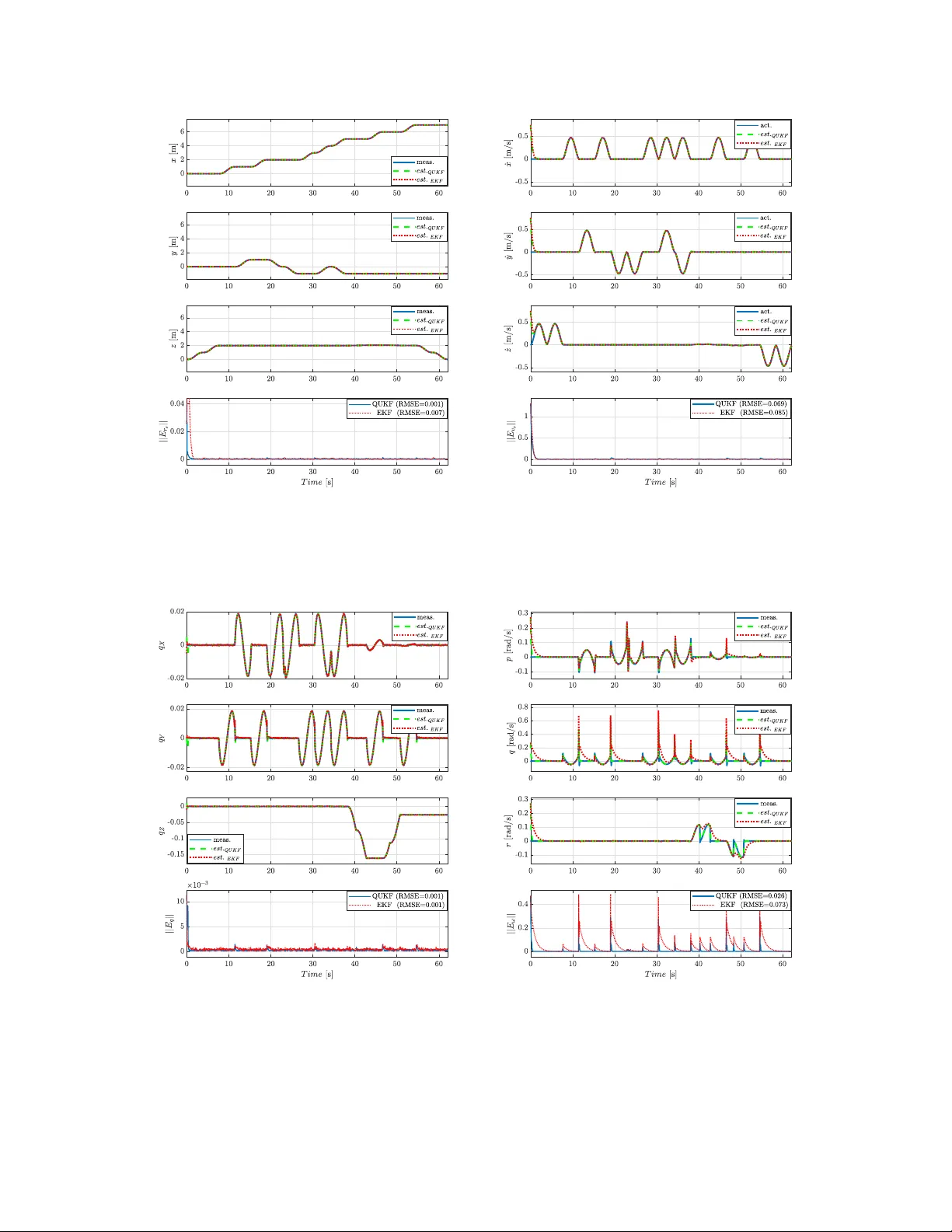
Authors: Hussein Naser, Hashim A. Hashim, Mojtaba Ahmadi
Personal use of this material is p ermitted. Permission from the author(s) and/or copyright holder(s), m ust b e obtained for all other uses. Please contact us and provide details if you believe this document breaches cop yrights. Quaternion-based Unscen ted Kalman Filter for Robust W renc h Estimation of Human-UA V Ph ysical In teraction Hussein Naser, Hashim A. Hashim, and Mo jtaba Ahmadi Abstract—This pap er in troduces an adv anced Quaternion- based Unscen ted Kalman Filter (QUKF) for real-time, robust estimation of system states and external wrenc hes in assistive aerial payload transp ortation systems that engage in direct ph ysical interaction. Unlike conv entional ltering techniques, the proposed approach employs a unit-quaternion represen- tation to inheren tly av oid singularities and ensure globally consisten t, drift-free estimation of the platform’s p ose and in teraction wrenches. A rigorous quaternion-based dynamic mo del is formulated to capture coupled translational and rotational dynamics under interaction forces. Building on this mo del, a comprehensiv e QUKF framework is established for state prediction, measuremen t up dates, and external wrenc h estimation. The prop osed form ulation fully preserv es the nonlinear characteristics of rotational motion, enabling more accurate and numerically stable estimation during physical in teraction compared to linearized ltering schemes. Extensiv e sim ulations v alidate the eectiveness of the QUKF, sho wing signican t improv emen ts ov er the Extended Kalman Filter (EKF). Specically , the QUKF ac hieved a 79.41% reduction in Ro ot Mean Squared Error (RMSE) for torque estimation, with a verage RMSE impro vemen ts of 79% and 56%, for position and angular rates, respectively . These ndings demonstrate enhanced robustness to measurement noise and modeling un- certain ties, providing a reliable foundation for safe, stable, and resp onsiv e h uman-UA V physical interaction in co operative pa yload transp ortation tasks. Index T erms—Co operative UA V s, pa yload transp ortation, F orce estimation, Unscen ted Kalman Filter, UKF, Quaternion dynamics, Physical in teraction, Admittance con trol. I. In tro duction A. Motiv ation A SSISTIVE Co operative pa yload transp ortation using Unmanned Aerial V ehicles (UA V s) is a rapidly ad- v ancing eld that utilizes m ulti-agent systems to carry and deliv er payloads exceeding the capacity of a single vehicle [ 1 ], [ 2 ]. This collab orative approach is vital in scenarios where traditional ground-based logistics are impractical, suc h as disaster-strick en regions, rugged terrains, or re- stricted urban environmen ts [ 3 ]. This approach enhances op erational eciency , reduces human risk, and provides access to otherwise inaccessible lo cations [ 4 ]. The m ulti- agen t systems can enable critical missions: for instance, This work was supp orted in part by the National Sciences and Engineering Researc h Council of Canada (NSER C), under the gran ts RGPIN-2022-04937. H. Naser, H. A. Hashim, and M. Ahmadi are with the Department of Mechanical and Aerospace Engineering, Carleton Univ ersity , Ottaw a, Ontario, K1S-5B6, Canada (e-mail: hhashim@carleton.ca). deliv ering medical supplies in searc h and rescue op erations [ 5 ], emplo ying AI-based vision for wildre sensing [ 6 ], and transp orting heavy materials in elev ated construction sites [ 7 ]. Ho w ever, the necessit y of synchronized mov emen t and stabilit y demands adv anced control algorithms and precise estimation of external interaction forces and torques [ 4 ]. These factors are essential for prev enting payload drops and ensuring safety and seamless op eration, particularly when human op erators are integrated in to the control lo op [ 8 ]. Consequently , o vercoming these co ordination c hallenges in co op erativ e payload transportation marks a signicant milestone in deploying UA V technology for complex, real-w orld applications. B. The F orce Sensing Challenge in Aerial Systems Con ven tionally , external wrenc hes are measured directly via 6D force-torque sensors [ 9 ]. How ever, for aerial plat- forms, such hardware is often prohibitiv e [ 10 ]. Beyond substan tial economic costs that limit the scalabilit y of m ulti-UA V systems, these sensors imp ose a severe mass p enalt y on weigh t-sensitiv e airframes, drastically reduc- ing op erational ight time [ 1 ]. F urthermore, integration is technically demanding, requiring sp ecialized moun t- ing, signal conditioning, and p o wer managemen t, which increases system complexity and introduces additional failure mo des [ 11 ]. The need for frequent calibration to mitigate measurement drift further complicates their use. Consequently , estimation-based approac hes that infer in teraction wrenc hes from existing on b oard sensors (e.g., IMUs and motor RPMs) are essential for developing practical, scalable h uman-UA V coop erative systems. C. Related W ork in Sensorless F orce Estimation A ccurate estimation of in teraction forces has emerged as a critical challenge in rob otics, driven b y the requirement for safe, robust, and adaptive con trol in collab orativ e en vironments [ 12 ]. Early research primarily fo cused on rob otic manipulators, utilizing force-torque sensors for tasks such as assembly and h uman-rob ot collab oration [ 13 ], [ 14 ]. How ever, as detailed in Section I-B , the inte- gration of suc h hardware into aerial platforms is often precluded by weigh t, cost, and complexity constraints. These drawbac ks hav e catalyzed a shift tow ard sensorless force estimation, where in teraction wrenches are inferred from system dynamics, kinematics, or data-driven models. H. Naser, H. A. Hashim, and M. Ahmadi, ”Quaternion-based Unscented Kalman Filter for Robust W rench Estimation of Human-UA V Physical In teraction,” Signal Processing, v ol. 245, pp. 110582, 2026. doi: 10.1016/j.sigpro.2026.110582 2 V arious observers and learning-based tec hniques hav e b een explored to bypass physical sensing. Nonlinear ob- serv ers hav e b een prop osed to estimate external distur- bances, including human-applied forces, payload eects, and friction [ 15 ]–[ 17 ]. F or instance, Ra jappa et al. [ 18 ] utilized residual-based estimators to decouple op erator inputs from other disturbances. While computationally ecien t, these observers often struggle with unmo deled dynamics and oer limited observ abilit y . Alternativ ely , learning-enhanced estimation approac hes hav e also b een explored to bypass ph ysical sensing hardware [ 19 ]. F or example, machine learning architectures, such as the adaptiv e recurren t neural netw ork (RNN) developed b y Sun et al. [ 20 ], oer high exibilit y and are capable of capturing complex, unmo deled h uman-rob ot interaction dynamics. Recent study [ 21 ] hav e introduced learning- based approaches that utilize transformer architectures for interaction force estimation. Ho wev er, despite their predictiv e p o wer, the heavy training requiremen ts, p oten- tial unpredictability outside of training distributions, and high computational o v erhead of deep learning models often render them impractical for time-critical applications like h uman-UA V co operation. Kalman-t yp e lters pro vide a systematic framew ork by com bining mo del predictions with sensor measurements [ 22 ], [ 23 ]; ho wev er, con v entional linear Kalman lters are often restricted by their strict assumptions of linearity and Gaussian noise. T o address these limitations, Extended Kalman Filters (EKF s) are frequen tly employ ed, y et they remain prone to linearization errors and Jacobian-related instabilities [ 24 ]. Building up on these nonlinear estimation tec hniques, the Unscen ted Kalman Filter (UKF) mitigates suc h issues b y utilizing the Unscented T ransformation (UT) to propagate sigma points through nonlinear dynam- ics, making it highly suitable for the complex nonlinearities inheren t in aerial systems [ 25 ], [ 26 ]. Despite these adv an- tages, standard UKF applications, such as the square-ro ot UKF used by Banks et al. [ 27 ] to estimate human-UA V in teraction forces, often rely on Euler angles which intro- duce the risk of gimbal lock singularities [ 28 ], [ 29 ]. T o en- sure global nonsingularit y , sev eral geometrically consisten t framew orks hav e b een developed to preserve rotational constrain ts, including the Multiplicative EKF (MEKF) [ 30 ], In v arian t EKF (IEKF) [ 31 ], and Lie Group-based UKF s on S O (3) or S E (3) [ 32 ]. While these metho ds t ypi- cally rely on local error-states and exponential mappings, our proposed QUKF directly propagates unit-quaternions within the unscented transform. This approach av oids singularities and preserves the full nonlinear kinematics of attitude evolution without the need for rst-order linearization or complex group retractions, thereby sim- plifying the estimation of translational states, rotational states, and external interaction wrenches. F rom a theoret- ical p ersp ectiv e, the unscen ted transform captures higher- order momen ts of nonlinear quaternion dynamics more eectiv ely than EKF-based schemes, leading to impro v ed accuracy under strong coupling b etw een rotational and translational dynamics [ 26 ]. F rom a practical standpoint, this quaternion-based UKF oers reduced computational complexit y and straigh tforward tuning, making it well- suited for real-time implemen tation on embedded UA V platforms during ph ysical human-UA V in teraction. This robustness is supported by recen t w ork [ 26 ] demonstrating that QUKF s outperform Euler-based form ulations in GPS- denied navigation b y maintaining a contin uous attitude represen tation. D. Motiv ation and Contributions Collectiv ely , previous research highlights the feasibilit y of sensorless force estimation and the ecacy of proba- bilistic ltering, particularly UKF and QUKF v ariants, in managing nonlinear, uncertain, and noisy dynamics. Ho w- ev er, current literature fo cuses predominan tly on ground manipulators or pure navigation tasks, with limited at- ten tion given to external wrench estimation for h uman- UA V co operative payload transportation. While robust, quaternion-a ware lters exist, their in tegration in to a uni- ed framew ork for real-time interaction force estimation in aerial systems remains an open c hallenge. Ov ercoming this gap is essential for implementing resp onsive admittance con trol and ensuring operational safet y without the w eigh t and cost penalties of physical sensors. In this pap er, w e bridge this gap by proposing a nov el Quaternion-based Unscen ted Kalman Filter (QUKF). This framew ork is designed to sim ultaneously estimate the full system state and external wrenches for an assistive aerial system during human-guided payload transp orta- tion. The k ey con tributions of this w ork are as follo ws: C1. Assistive Co op erativ e F ramework: The design of a comprehensiv e framework for an assistive coop erativ e pa yload transp ortation that incorp orates direct phys- ical h uman guidance and in teraction. C2. Quaternion-based Dynamic Mo deling: The deriv ation of a rigorous quaternion-based dynamic model of the UA V-payload system, providing a robust mathemati- cal foundation for b oth stability analysis and mo del- based estimation. C3. Geometric QUKF Estimator: The developmen t of a no vel geometric QUKF for the concurren t estima- tion of navigation states and external in teraction wrenc hes, eectively eliminating the requiremen t for 6-DoF force-torque sensors. C4. Comprehensive V alidation: A high-delit y sim ulation study integrating the QUKF estimator with a stan- dard admittance controller to: (i) enable seamless ph ysical human-UA V interaction, (ii) quantitativ ely v alidate estimation accuracy against baseline meth- o ds (e.g., EKF), and (iii) demonstrate a robust, singularit y-free solution for all-attitude ight regimes. The rest of the paper is organized as follows: Section II elab orates on the notation used in this pap er and pro vides mathematical preliminaries and orien tation represen tation metho ds. Section I II presents a comprehensive description of problem formulation and system mo deling. Section IV details the QUKF implemen tation. The simulation 3 n umerical results are provided in Section V . Finally , Section VI concludes the article and outlines p otential future w ork. I I. Preliminaries A. Notation The notation utilized throughout this pap er is dened as follo ws: The sets of real and positive real num bers are denoted b y R and R + , respectively , while S 3 represen ts the three-unit sphere. The space of n × n real matrices is denoted by R n × n . The terms I n and 0 n represen t the n × n iden tity and zero matrices. F or a vector p ∈ R n , its transp ose is denoted b y p ⊤ and its Euclidean norm is dened as ∥ p ∥ = p ⊤ p . F or any v ector p ∈ R 3 , the corresp onding skew-symmetric matrix [ p ] × ∈ so (3) is dened as: p × = 0 − p 3 p 2 p 3 0 − p 1 − p 2 p 1 0 ∈ so (3) , p = p 1 p 2 p 3 . (1) The inv erse skew-symmetric operator vex( · ) is a mapping from so (3) in ( 1 ) to R 3 , (vex ( · ) : so (3) → R 3 ), such that [ 26 ]: v ex ([ p ] × ) = p ∈ R 3 . (2) while the anti-symmetric pro jection op erator P a ( · ) is a mapping from R 3 × 3 to so (3) , ( P a ( · ) : R 3 × 3 → so (3) ), such that [ 26 ]: P a ( B ) = 1 2 ( B − B ⊤ ) ∈ so (3) , ∀ B ∈ R 3 × 3 . (3) B. Represen tation of a rigid-b ody attitude in 3D space The attitude (orientation) of a rigid b o dy moving in three-dimensional (3D) space can b e describ ed through sev eral mathematical frameworks. These representations relate tw o distinct co ordinate systems, a world inertial frame I f = { O, X, Y , Z } , which is global and Earth-xed, and a bo dy-xed frame B f = { o, x b , y b , z b } , attached to the Cen ter-of-Mass (CoM) of the moving rigid-b ody . A brief description of some orien tation representation metho ds will be given as follo ws: 1) Sp ecial Orthogonal Group S O (3) : The orientation is most fundamentally represented by a rotation matrix R ∈ R 3 × 3 . This matrix belongs to the Sp ecial Orthogonal Group S O (3) , dened b y: S O (3) := { R ∈ R 3 × 3 | det ( R ) = +1 , and RR ⊤ = I 3 } , (4) where det( · ) denotes the determinan t. The rotation matrix R provides a unique, universal representation for every ph ysical orientation of the rigid b ody [ 33 ]. 2) Euler angles: Euler angles are widely adopted due to their intuitiv e visualization of rotations ab out the principal axes: roll ( ϕ ) about x , pitch ( θ ) ab out y , and y aw ( ψ ) ab out z [ 4 ]. How ever, despite their simplicity , they are mathematically limited by singularities kno wn as gimbal lo c k, which can compromise stability in high- maneuv erability applications [ 33 ]. 3) Angle-axis: In this metho d, the relative orien tation b et w een the inertial and b ody-xed reference frames can also b e expressed as a single rotation of angle α ∈ R around a unit v ector b = [ b 1 , b 2 , b 3 ] ⊤ ∈ S 2 , where ∥ b ∥ = b 2 1 + b 2 2 + b 2 3 = 1 . While conceptually useful, this representation also encoun ters singularities in specic congurations. The parameters ( α, b ) can b e extracted from a giv en rotation matrix R via the mapping ( α, b ( R )) : S O (3) → S 2 × R ) using the op erators in ( 2 ) and ( 3 ) in the follo wing relations [ 33 ]: b ( R ) = 1 sin( α ) v ex ( P a ( R )) ∈ S 2 , α ( R ) = arccos T r ( R ) − 1 2 ∈ R . (5) 4) Ro driguez vector: The Ro driguez v ector P = [ p 1 , p 2 , p 3 ] ⊤ ∈ R 3 enco des rotation suc h that its direction aligns with the rotation axis and its magnitude is prop or- tional to the rotation angle. It can b e derived from the angle-axis form via the mapping ( P ( α , b ) : R × S 2 → R 3 ) as follo ws: P ( α, b ) = αb ∈ R 3 . (6) Giv en Ro driguez vector, the corresp onding rotation ma- trix R ( P ) can b e obtained via the mapping ( R ( P ) = R 3 → S O (3) ) as follo ws: R ( P ) = ( I 3 + [ P ] × )( I 3 − [ P ] × ) − 1 ∈ S O (3) . (7) Lik e Euler angles and angle-axis represen tations, the Ro- driguez vector represen tation is sub ject to mathematical singularities [ 33 ]. 5) Quaternion : Quaternions are four-dimensional h y- p ercomplex num bers that provide a globally non-singular represen tation of 3D rotations. A quaternion q = [ q w , q ⊤ v ] ⊤ ∈ S 3 is dened as q = q w + q x i + q y j + q z k , where i , j , and k refer to the standard basis vectors, q w ∈ R is the scalar part, q v = [ q x , q y , q z ] ⊤ ∈ R 3 is the vector part, and q ∗ = q w − q x i − q y j − q z k is the complex conjugate of the quaternion q . A unit-quaternion is a quaternion satisfying ( ∥ q ∥ = 1 and q − 1 = q ∗ ) , where q − 1 represen ts the in v erse of q . Quaternions are generally preferred ov er Euler angles for UA V applications as they av oid gimbal lo c k and allow for smo oth in terp olation of attitudes. The quaternion multiplication and conjugation operations are fundamental for UA V orien tation representation. The pro duct of tw o quaternions q 1 and q 2 , is giv en b y: q 1 ⊗ q 2 = q w 1 q w 2 − q ⊤ v 1 q v 2 q w 1 q v 2 + q w 2 q v 1 + [ q v 1 ] × q v 2 , (8) with q ⊗ q − 1 = q I and q ⊗ q I = q , where q I = [1 , 0 , 0 , 0] ⊤ is the quaternion identit y . Quaternion multiplication is asso ciativ e pro cess but non-commutativ e. A quaternion is mapp ed to a rotation matrix R ( q ) ∈ S O (3) via the mapping ( R ( q ) : S 3 → S O (3) ), as follo ws: R ( q ) = ( q 2 w − ∥ q v ∥ 2 ) I 3 + 2 q v q ⊤ v − 2 q w [ q v 1 ] × , = I 3 + 2 q w [ q v 1 ] × + 2[ q v 1 ] 2 × , (9) 4 Con versely , the rotation matrix can b e remapp ed to a quaternion q ( R ) via the mapping ( q ( R ) : S O (3) → S 3 ) , as [ 33 ]: q ( R ) = q w q x q y q z = 1 2 1 + R (1 , 1) + R (2 , 2) + R (3 , 3) 1 4 q w ( R (3 , 2) − R (2 , 3) ) 1 4 q w ( R (1 , 3) − R (3 , 1) ) 1 4 q w ( R (2 , 1) − R (1 , 2) ) . (10) Giv en a quaternion and/or a rotation vector P , and in view of equations ( 5 ), ( 6 ), ( 7 ), ( 9 ) and ( 10 ), we obtain the follo wing relationships: P ( q ) = α ( R ( q )) ∗ b ( R ( q )) ∈ R 3 , q ( P ) = q ( R ( P )) = cos( α 2 ) b sin( α 2 ) ∈ S 3 . (11) 6) Summation, subtraction, and weigh ted av erage: Direct summation and subtraction are not applicable b et w een quaternions and rotation vectors. In view of equations ( 8 ) and ( 11 ), one has [ 26 ]: q ⊕ P := q ( P ) ⊗ q ∈ S 3 , q ⊖ P := q ( P ) − 1 ⊗ q ∈ S 3 , (12) where ⊕ and ⊖ represent the quaternion ( q ∈ S 3 ) and vec- tor ( P ∈ R 3 ) side-dep endent summation and subtraction op erators, resp ectively . Using equation ( 8 ), ( 11 ) and ( 12 ), one can subtract tw o subsequen t quaternions and map the result to a rotation vector at the same time ( S 3 × S 3 → R 3 ), as follo ws: q 1 ⊖ q 2 := P ( q 1 ⊗ q − 1 2 ) ∈ R 3 . (13) The resultan t rotation v ector P ( q 1 ⊗ q − 1 2 ) in ( 13 ) physically means the orientation error betw een the tw o quaternions. The w eigh ted a verage of a set of scalar w eights S W = { w i } and quaternions S q = { q i } is giv en as follo ws [ 26 ], [ 34 ]: W Ave( S q , S W ) = Eigv ec ( A ) ∈ S 3 , (14) where A is a matrix given as A ( S q , S W ) = w i q i q ⊤ i ∈ R 4 × 4 and Eigv ec ( A ) is the unit eigenv ector of the matrix A corresponding to its maximum eigen v alue. I II. Problem formulation In h uman-UA V co operative payload transp ortation, ac- curate estimation of external wrenches is critical for op era- tional safet y . This task is inherently challenging due to the highly nonlinear dynamics of the aerial platforms and the sto c hastic nature of human interaction. T o address these c hallenges, this work prop oses an inno v ativ e, sensorless metho d for estimating interaction forces and torques. The system under study comprises tw o quadrotors collab ora- tiv ely transp orting a rigidly attac hed pa yload. Through this setup, a human op erator intuitiv ely guides the formation by applying physical forces directly to the payload. These in teraction wrenc hes are estimated online using a Quaternion-based Unscented Kalman Filter (QUKF), which av oids the weigh t and complexity of ph ysical force-torque sensors. The resulting estimates are T ABLE I: Nomenclature. Symbol Denition I f , L f , B f i Inertial- frame, pa yload b ody-frame, i th UA V b o dy-frame. r i , v i , ˙ v i i th UA V position, velocity , and acceleration in I f . r l , v l , ˙ v l Pa yload p osition, velocity , acceleration in I f . r , v , ˙ v System p osition, velocity , and acceleration in I f . m i , J i i th UA V mass and moment of inertia. m l , J l Pa yload mass and momen t of inertia. m s , J T otal mass and moment of inertia of en tire system. g Gravit y . ϖ Angular sp eed of each quadrotor’s rotor. ι Distance from quadrotor’s CoM to the rotor’s axis. k t , k m Thrust and drag constan ts. F i , T i i th UA V f orce and torque exerted on payload. S O (3) Special Orthogonal Group. so (3) Space of (3 × 3) skew-symmetric matrices. q Quaternion q ∈ S 3 . R ( q ) Rotation matrix R ( q ) ∈ S O (3) . ω , ˙ ω System angular v elocity and acceleration in b ody-frame. F th T otal thrust produced b y tw o quadrotors. U τ T otal (rolling, pitc hing, ya wing) momen ts of the system. τ h , ˆ τ h External physical interaction wrenc h and its estimate. x k , ˆ x k State vector and its estimate at time k . N State vector length. w k , v k Process and measurement noise vectors at time k . Q , R Process and measurement co v ariance matrices. u k Control input vector at time k . y k Output vector at time k . L k Sigma p oin ts matrix at time k . K Kalman gain matrix at time k . P Error cov ariance matrix. pro cessed by an admittance con troller to translate h uman ph ysical guidance in to precise 3D motion commands. F or the purp ose of control design, the m ulti-UA V-payload assem bly is mo deled as a single in tegrated rigid b ody . The notation and symbols employ ed throughout this man uscript are detailed in T able I . A. System Mo del F or the system mo deling, we dene a global inertial frame, I f = { O, X , Y , Z } , with a p ositiv e Z -axis up- w ard. A b o dy-xed frame L f = { o, x l , y l , z l } is attached to the payload’s center of mass (CoM), and a frame B f i = { o i , x b i , y b i , z b i } is attac hed to the CoM of each quadrotor ( i = 1 , 2) ; all the b o dy-xed frames share the same upw ard z -axis orientation. The p osition and v elocity of the i th quadrotor in I f are given by r i = [ x i , y i , z i ] ⊤ and v i = ˙ r i , resp ectively . Due to the rigid connection, the system’s rotational dynamics are describ ed by a single unit-quaternion q = [ q w , q ⊤ v ] ⊤ ∈ S 3 and a common angular v elo cit y v ector ω = [ p, q, r ] ⊤ expressed in the b o dy frame. 1) Quadrotor Dynamics: Referring to Figure 1 , the translational and angular dynamics of the i th quadrotor are mo deled using Newton-Euler formulation, as follows [ 29 ], [ 35 ]: ˙ q = 1 2 Ξ( ω ) q , ˙ r i = v i , ˙ v i = R ( q ) u i 1 m i E z − g E z − F i m i , ˙ ω = J − 1 i ( u iτ − ω × J i ω − T i ) , (15) 5 Fig. 1: F ree b ody diagram of the system comp onen ts. where Ξ( ω ) = 0 − ω ⊤ ω − ω × ∈ R 4 × 4 , m i ∈ R and J i ∈ R 3 × 3 are the mass and inertia matrix; ˙ v i , ˙ ω ∈ R 3 are the translational and angular accelerations; u i 1 ∈ R is the generated thrust measured in the b o dy- xed reference frame; g ∈ R is gravit y; E z = [0 , 0 , 1] ⊤ is a unit v ector along z -axis; u iτ = [ u i 2 , u i 3 , u i 4 ] ⊤ ∈ R 3 are the roll, pitc h, and ya w moments about x b i , y b i , z b i ; and F i , T i ∈ R 3 are the interaction force and torque due to the pa yload connection. The generated thrust and momen ts of the i th quadrotor are giv en as follo ws: u i 1 u iτ = f i 1 + f i 2 + f i 3 + f i 4 ι ( f i 2 − f i 4 ) ι ( f i 3 − f i 1 ) τ i 1 − τ i 2 + τ i 3 − τ i 4 = 1 1 1 1 0 ι 0 − ι − ι 0 ι 0 ν − ν ν − ν f i 1 f i 2 f i 3 f i 4 . (16) Eac h rotor of the i th quadrotor generates a thrust ( f ij = k t ϖ 2 ij ) , which is prop ortional to the squared rotor’s angular speed ϖ ij , where k t is the thrust constan t. Simi- larly , the moment pro duced b y each rotor is ( τ ij = k m ϖ 2 ij ) , with k m b eing the drag constant, and ν = k m /k t . The parameter ι represents the distance from the quadrotor’s CoM to the axis of rotation of eac h rotor. The parameter ι is assumed to be the same for all rotors. 2) P ayload Dynamics: Referring to Figure 1 , let the pa yload CoM p osition and v elo cit y in I f b e r l = [ x l , y l , z l ] ⊤ and v l = ˙ r l , resp ectiv ely . The pa yload transla- tional and rotational dynamics are then given b y: ˙ q = 1 2 Ξ( ω ) q , ˙ r l = v l , ˙ v l = ( F 1 + F 2 ) m l − g E z , ˙ ω = J − 1 l ( T 1 + T 2 ) − ω × J l ω + ( l 1 × F 1 ) + ( l 2 × F 2 ) , (17) where m l ∈ R denotes the payload mass, and J l ∈ R 3 × 3 is its inertia matrix. The translational acceleration is ˙ v l ∈ R 3 . The forces ( F 1 , F 2 ) ∈ R 3 and torques ( T 1 , T 2 ) ∈ R 3 are applied b y the quadrotors at the rigid connection p oin ts. The corresponding force momen ts, ( l 1 × F 1 ) and ( l 2 × F 2 ) , dep end on the v ector ( l i = r i − r l ) , where r i and r l are the CoM p osition v ector of the i th quadrotor and the payload, resp ectiv ely . 3) Dynamics of the entire Aerial system: T o derive the dynamic equations of the entire system, w e adopt the follo wing assumptions. Assumption 1. . A. The system consists of three rigid comp onen ts con- nected rigidly , each with distinct physical prop erties. B. The tw o quadrotors are iden tical and share the same geometric and ph ysical c haracteristics. C. The en tire system is symmetric ab out the X and Y axes. D. The aero dynamic drag forces and torques are ne- glected. E. The payload is mo deled as a circular b eam with mass m l , length L , and cross-sectional radius a l . Let r = [ x, y , z ] ⊤ and v = ˙ r denote the p osition and v elo cit y of the system CoM in I f . Based on Assumption 1 and referring to Figure 1 , the system dynamic model is deriv ed by combining the dynamics of the quadrotors in ( 15 ) and the pa yload in ( 17 ), as follo ws: ˙ q = 1 2 Ξ( ω ) q , ˙ r = v, ˙ v = R ( q ) F th m s E z − g E z + F h m s , ˙ ω = J − 1 ( U τ − ω × J ω + M h ) , (18) where ( m s = 2 i =1 m i + m l ) ∈ R is the total mass of the system, and J ∈ R 3 × 3 its total inertia. The translational acceleration is ˙ v ∈ R 3 . External h uman in teraction is mo deled b y force F h ∈ R 3 and torque M h ∈ R 3 . The quadrotors generate a total thrust F th ∈ R and control momen ts U τ ∈ R 3 , expressed in the system b o dy-xed frame. Since each quadrotor pro duces inputs in its own lo cal frame, their contributions must b e mapp ed to the system dynamics as follo ws: F th U τ = C u c , (19) where u c ∈ R 4 N represen ts the quadrotors’ con trol inputs v ector. u c = [ u 11 , u 12 , u 13 , u 14 , u 21 , u 22 , u 23 , u 24 ] ⊤ , (20) and C ∈ R 4 × 4 N represen ts the conguration matrix that is constant and dep ends on the system conguration. F or the rigidly connected system in this work, C is given as follo ws: C = 1 0 0 0 1 0 0 0 l 1 (2) 1 0 0 l 2 (2) 1 0 0 − l 1 (1) 0 1 0 − l 2 (1) 0 1 0 0 0 0 1 0 0 0 1 . (21) Remark 1. In the prop osed control scheme, [ F th , U τ ] ⊤ is rst calculated and then utilized to determine ( u c ) in ( 20 ), allo wing the quadrotors to achiev e the desired tracking con trol. Notably , the system in ( 19 ) is underdetermined, 6 A erial T ran sp o rtat i o n Sy stem ( QUKF ) Fo rce/t o rq u e Est i m at i o n M o d u l e Exte rn al Fo rces and D i stur b ances Desi red T raj ect o ry O u t er Lo o p A d m i t t ance C o n t ro l l er A d apti v e Ba ckstepp i n g Po sit i o n C o n t ro l l er FN TSMC A t t i t u d e Con t ro l l er In n er Lo o p Con t ro l Bl o ck Fig. 2: Sc hematic blo c k diagram of the con trol system. as it provides only four equations for eight unknown v ariables. T o resolv e this, the solutions are optimized by minimizing a cost function J ( u c ) : R 8 → R , dened as follo ws: u ∗ c = argmin { J | [ F th , U τ ] ⊤ = C u c } , (22) here, the cost function J in ( 22 ) is dened as follo ws: J = 2 i =1 4 j =1 κ ij u 2 ij , (23) where κ ij represen ts the coecients of the cost function, whic h can be used to construct a matrix Λ ∈ R 8 × 8 . Con- sequen tly , the cost function J in ( 23 ) can be reformulated as ( J = ∥ Λ u c ∥ 2 2 ) , where Λ is dened as follows: Λ = diag ( κ ij ) , i = 1 , 2 , j = 1 , ..., 4 . (24) Utilizing C from ( 21 ) and Λ from ( 24 ), an optimal solution can b e computed using the Mo ore-P enrose inv erse as follo ws [ 36 ]: u ∗ c = Λ − 1 ( C Λ − 1 ) + [ F th , U τ ] ⊤ , = Λ − 2 C ⊤ ( C Λ − 2 C ⊤ ) − 1 [ F th , U τ ] ⊤ , (25) here, the sup erscript + denotes the Mo ore-P enrose in- v erse, and the optimized solution u ∗ c in ( 25 ) satises the conditions outlined in Remark 1 . B. Assistiv e Control Sys tem Architecture T o facilitate in tuitiv e physical h uman-UA V interaction, the control architecture integrates three primary ob jec- tiv es: (i) h uman-led guidance, (ii) reference tra jectory trac king, and (iii) stabilization of the co op erativ e pa yload transp ortation system. The p osition subsystem is stabi- lized via a Bac kstepping control law, while a F ast Non- singular T erminal Sliding Mo de Controller (FNTSMC) is employ ed to ensure robust, fast attitude regulation. F urthermore, an admittance control la y er is incorp orated to mo dulate the interaction forces, enabling seamless and in tuitive co operation b etw een the human op erator and the UA V. The integrated control framework is depicted in Figure 2 . F or a comprehensive treatment of the con troller’s design and formal stabilit y deriv ations, the reader is referred to [ 4 ], [ 8 ]. C. Estimation of external h uman-exerted wrenc h F or estimation purp oses and in order to nd a unied expression for the interaction wrenc h, the dynamic mo del in ( 18 ) can be written in one compact form as follo ws: τ h = M ¨ χ + G ( ˙ χ ) + W ( χ ) u, (26) where τ h = [ F ⊤ h , M ⊤ h ] ⊤ ∈ R 6 represen ts the external in teraction wrench, ¨ χ = [ ˙ v ⊤ , ˙ ω ⊤ ] ⊤ ∈ R 6 is the generalized acceleration v ector, u = [ F th , U ⊤ τ ] ⊤ ∈ R 4 is the vector of con trol inputs, M ∈ R 6 × 6 is the p ositiv e denite inertia matrix, G ( ˙ χ ) ∈ R 6 is a vector con tains the gravit y and the cross pro duct terms in ( 18 ), W ( χ ) ∈ R 6 × 4 is the con trol input coecients matrix. These matrices are giv en as follo ws: M = m s I 3 0 3 0 3 J ∈ R 6 × 6 , G = m s g E z ω × J ω ∈ R 6 , W ( χ ) = − R ( q ) E z 0 3 0 3 × 1 − I 3 ∈ R 6 × 4 , where I 3 and 0 3 are identit y and zero matrices with dimension of ( 3 × 3 ), resp ectiv ely . Let ˆ τ h = [ ˆ F ⊤ h , ˆ M ⊤ h ] ⊤ ∈ R 6 represen ts the estimation of the external interaction wrenc h, and let its rate of c hange o ver time b e giv en as: ˙ ˆ τ h = A τ h − ˆ τ h = − A ˆ τ h + A M ¨ χ + G ( ˙ χ ) + W ( χ ) u , (27) where A ∈ R 6 × 6 is a matrix that will b e designed to guarantee that ( ˆ τ h → τ h ) . Since we hav e no prior kno wledge ab out the external interaction wrench and its deriv ative except that it will not be rapidly v arying during the physical interaction b et w een the assistive aerial system and the human op erator, it is conv enien t to assume the follo wing: ˙ τ h = 0 . (28) Let us dene the wrenc h error as follo ws: e = τ h − ˆ τ h , (29) Dieren tiating ( 29 ) with resp ect to time and use ( 28 ), results in: ˙ e = ˙ τ h − ˙ ˆ τ h = A ˆ τ h − Aτ h . (30) Based on ( 29 ), equation ( 30 ) can b e expressed in the form of error dynamics as follo ws: ˙ e + Ae = 0 , (31) F rom ( 31 ), the error conv ergence ( e → 0) can b e guaran teed by an appropriate design of A . As seen in ( 27 ), computing ˙ ˆ τ h requires ( χ, ˙ χ, ¨ χ ) . While χ and ˙ χ can b e measured or estimated using standard metho ds, ¨ χ (particularly the angular acceleration) is typically not a v ailable. Therefore, an acceleration-free formulation of ( 27 ) is required. T o this end, the following auxiliary v ector is in tro duced [ 37 ]: Υ = ˆ τ h − Γ( ˙ χ ) , (32) Dieren tiating ( 32 ) with resp ect to time results in: ˙ ˆ τ h = ˙ Υ + ∂ Γ( ˙ χ ) ∂ ˙ χ ¨ χ. (33) 7 Using ( 32 ) and ( 33 ) in equation ( 27 ), results in: ˙ Υ + ∂ Γ( ˙ χ ) ∂ ˙ χ ¨ χ = − A Υ + Γ( ˙ χ ) + A M ¨ χ + G ( ˙ χ ) + W ( χ ) u , (34) Simplifying ( 34 ), the acceleration-free dynamics of the external in teraction wrench is expressed as follows: ˙ Υ = − A Υ + A G ( ˙ χ ) + W ( χ ) u − Γ( ˙ χ ) , ˆ τ h = Υ + Γ( ˙ χ ) , (35) where ( ∂ Γ( ˙ χ ) /∂ ˙ χ ) is chosen as follows: ∂ Γ( ˙ χ ) ∂ ˙ χ = AM . (36) F rom ( 31 ) and ( 36 ), the matrix A m ust b e designed to guaran tee the asymptotic stabilit y of the error dynamics. W e pro ceed b y considering the follo wing: Γ( ˙ χ ) = δ ˙ χ ⇒ A = δM − 1 , where δ ∈ R + is a p ositiv e tunable gain. While a comprehensiv e treatment of the ov erall control system’s stabilit y can b e found in [ 4 ], [ 8 ], [ 38 ], the stabilit y of the prop osed external wrench estimation scheme is go verned b y the error dynamics derived in equation ( 31 ). The stabilit y margin of this estimator is in trinsically tied to the design matrix A . Since δ is a p ositiv e gain and M is the p ositiv e denite inertia matrix, the error dynamics are guaran teed to b e asymptotically stable. This ensures that the estimated wrench ( ˆ τ h ) consistently conv erges to the actual external interaction wrenc h ( τ h ) without sustained oscillations during ph ysical in teraction. IV. Quaternion-based Unscen ted Kalman Filter (QUKF) The UKF is an adv anced estimation algorithm designed for nonlinear systems with sto c hastic noise. Unlike the traditional Extended Kalman Filter (EKF), whic h relies on rst-order linearization, the UKF addresses nonlinear- ities more accurately through deterministic sampling. In this work, the QUKF is designed to estimate the full augmen ted state v ector, comprising p osition, orien tation, linear/angular velocities, and the external interaction wrenc h, given noisy position, orientation (quaternion) and angular velocity data. In sto c hastic estimation problems, it is often assumed that the pro cess and measurement noise are added linearly as follo ws: x k = f ( x k − 1 , u k − 1 ) + w k − 1 , y k = h( x k ) + v k , (37) where x k , y k , and u k represen t the state, output, and input v ectors at discrete time k . The functions f and h denote the nonlinear state transition and observ ation mappings, resp ectiv ely . The noise terms w k and v k are assumed to b e indep enden t, zero-mean, white Gaussian processes with co v ariance matrices Q and R [ 39 ]: w k ∼ N (0 , Q k ) , v k ∼ N (0 , R k ) , E [ w k v ⊤ k ] = 0 . (38) In this formulation, the pro cess noise w k accoun ts for un- mo deled dynamics, aero dynamic uncertainties, and v ari- ations in human-applied forces, while the measurement noise v k captures sensor-level imperfections. By explicitly incorp orating these sources of noise in to the UKF predic- tion and up date steps, their eects are propagated through the nonlinear dynamics via the unscented transformation. In view of ( 37 ), the state transition function that mo dels the relationship b et ween the current state, the previous state, and the input vectors can b e deriv ed by augmen ting the nonlinear system dynamics in ( 18 ) with the external wrenc h evolution in ( 35 ). This results in the following con tinuous-time augmen ted system: ˙ x = f ( x, u ) , (39) with the augmen ted state vector dened as x = [ q , r , v , ω , Υ] ⊤ ∈ R 19 , where q ∈ S 3 , r , v , ω ∈ R 3 , and Υ ∈ R 6 . Unlike con v entional methods that treat external disturbances as lump ed noise, this framew ork em b eds the external wrench dynamics in to the state v ector to capture the inherent coupling betw een the platform’s attitude and external interactions during the sigma-point propagation step. The righ t-hand side of ( 39 ) is expressed as: f ( x, u ) = ˙ q ˙ r ˙ v ˙ ω ˙ Υ = 1 2 Ξ( ω ) q v R ( q ) u (1) m s E z − g E z J − 1 u (2 : 4) − ω × J ω A − Υ + G + W u − Γ . (40) T o facilitate estimation ,the augmented dynamics in ( 39 ) can b e restructured into a geometric form, consisten t with the methodologies in [ 26 ], [ 40 ]: ˙ x = f c ( q , r , ω , u ) x ˙ q ˙ r ˙ v ˙ ω ˙ Υ 0 = 1 2 Ξ( ω ) 0 0 0 0 0 0 I 3 0 0 0 0 0 0 R ( q ) u (1) m s E z − g E z 0 0 0 0 J − 1 u (2 : 4) − ω × J ω 0 0 0 0 A − Υ + G + W u − Γ 0 0 0 0 0 q r v ω Υ 1 , (41) where the state is extended to x ∈ R 20 for geometric recon- struction. This con tin uous system in ( 41 ) can b e discretized o ver a sampling interv al T using the matrix exp onential: q k r k v k ω k Υ k 1 = exp(f c k − 1 T ) q k − 1 r k − 1 v k − 1 ω k − 1 Υ k − 1 1 , (42) where f c k − 1 = f c ( q k − 1 , r k − 1 , ω k − 1 , u k − 1 ) and x k = [ q k , r k , v k , ω k , Υ k , 1] ⊤ represen ts the discrete state v ector. The measured signals: p osition r m k , orientation q m k , and angular v elo cit y ω m k are aected by additiv e noise, as described in ( 38 ). Giv en the assumption that pro cess noise remains constant ov er T , the contin uous cov ariance is discretized as Q k = Q T . 8 A. Unscen ted T ransformation (UT) The Unscented T ransformation (UT) is the core mechanism of the UKF, allo wing for the precise propagation of the mean ¯ x and cov ariance P x of a random v ariable x through the nonlinear functions. By utilizing a deterministic set of sigma p oin ts, the UT av oids the linearization errors inheren t in the EKF. The selection of these p oints is go verned by three scaling parameters: 1) Primary scaling ( φ ) : Controls spread of sigma p oints ( 10 − 4 to 1 ). Smaller v alues produce tigh ter clusters; larger v alues giv e a wider spread. 2) Secondary scaling ( γ ) : Incorp orates prior distribution kno wledge (optimally γ = 2 for Gaussian distributions). 3) T ertiary scaling ( σ ) : Typically set to 0. The weigh ts for the mean ( µ m ) and co v ariance ( µ c ), along with an additional scaling factor η , are dened as [ 39 ]: η = φ 2 ( N + σ ) − N , µ m 0 = η / ( N + η ) , µ c 0 = η / ( N + η ) + 1 − φ 2 + γ , µ m i = µ c i = 1 / [2( N + η )] , i = 1 , ..., 2 N , (43) where N is the state dimension. The 2 N + 1 sigma p oin ts are generated using the Cholesky factor of the co v ariance matrix: L = ¯ x, ¯ x + √ N + η √ P x , ¯ x − √ N + η √ P x , (44) P assing these p oin ts through the nonlinear function f yields the transformed set: S ( i ) = f ( L ( i ) ) , i = 0 , 1 , ..., 2 N . (45) Finally , the p osterior mean and co v ariance are reconstructed via weigh ted a veraging: ¯ y ≈ 2 N i =0 µ m i S ( i ) , P y ≈ 2 N i =0 µ c i ( S ( i ) − ¯ y )( S ( i ) − ¯ y ) ⊤ . (46) B. QUKF Implemen tation The QUKF recursion begins with ˆ x 0 and P 0 . Unlik e conv en- tional UKF, quaternions require sp ecial handling, since they cannot be directly added/subtracted (see Section II-B5 , ( 12 ), ( 13 )), and must satisfy the unit norm constraint (four elements, three DoF) whic h requires co v ariance adjustmen ts. Th us, the initial state and cov ariance are dened as: ˆ x 0 = ˆ x ⊤ 0 ,q , ˆ x ⊤ 0 ,nq ⊤ ∈ R N , P 0 = blkdiag P 0 ,q , P 0 ,nq ∈ R ( N − 1) × ( N − 1) , (47) with ˆ x 0 ,q ∈ S 3 represen ts the quaternion term with its co v ariance P 0 ,q ∈ R 3 × 3 that satises the unit constraint and ˆ x 0 ,nq ∈ R N − 4 represen ts the non-quaternion terms with co v ariance P 0 ,nq ∈ R ( N − 4) × ( N − 4) . A t eac h time step k , sigma p oin ts are generated from the prior state estimate ˆ x k − 1 ∈ R N and co v ariance P k − 1 ∈ R ( N − 1) × ( N − 1) using a modied v ersion of equation ( 44 ) as: L k − 1 = ˆ x k − 1 , ˆ x k − 1 + N − 1 + η P k − 1 , ˆ x k − 1 − N − 1 + η P k − 1 . (48) T o handle the addition and subtraction op erations of the quaternions and rotation vectors in ( 48 ), let ˆ C k − 1 = N − 1 + η P k − 1 ∈ R ( N − 1) × ( N − 1) , ˆ c ( i ) k − 1 = N − 1 + η P k − 1 ∈ R ( N − 1) ( i th column of ˆ C k − 1 ) divide ˆ c ( i ) k − 1 and ˆ x k − 1 in to their orien tation and non-orientation comp onen ts, as it was done in ( 47 ): ˆ x k − 1 = ˆ x ⊤ k − 1 ,q , ˆ x ⊤ k − 1 ,nq ⊤ ∈ R N , ˆ c ( i ) k − 1 = ˆ c ( i ) ⊤ k − 1 ,r , ˆ c ( i ) ⊤ k − 1 ,nr ⊤ ∈ R N − 1 . (49) utilizing the custom addition and subtraction op erators in ( 12 ) to map from ( S 3 × R 3 → S 3 ), equation ( 48 ) is mo died to calculate the sigma p oin ts as follows: L k − 1 = ˆ x k − 1 , ˆ x k − 1 ⊕ ˆ C k − 1 , ˆ x k − 1 ⊖ ˆ C k − 1 ∈ R N × (2 N − 1) , (50) where the addition and subtraction expressions in ( 50 ) are giv en as follows: ˆ x k − 1 ⊕ ˆ C k − 1 ≡ ˆ x k − 1 ,q ⊕ ˆ c ( i ) k − 1 ,r ˆ x k − 1 ,nq + ˆ c ( i ) k − 1 ,nr ∈ R ( N × N − 1) , ˆ x k − 1 ⊖ ˆ C k − 1 ≡ ˆ x k − 1 ,q ⊖ ˆ c ( i ) k − 1 ,r ˆ x k − 1 ,nq − ˆ c ( i ) k − 1 ,nr ∈ R ( N × N − 1) . Sigma p oints in ( 50 ) are propagated through the nonlinear state transition function, f in ( 42 ) as: L ( i ) k | k − 1 = f ( L ( i ) k − 1 , u k − 1 ) , i = 0 , 1 , ..., 2( N − 1) , (51) with pro cess noise excluded (zero-mean additiv e). The w eight v ectors in ( 43 ) and the weigh ted a v eraging in ( 46 ) also adapt to reect the reduced dimensionality as: η = φ 2 (( N − 1) + σ ) − ( N − 1) , µ m 0 = η / (( N − 1) + η ) , µ c 0 = η / (( N − 1) + η ) + 1 − φ 2 + γ , µ m i = µ c i = 1 / (2(( N − 1) + η )) , i = 1 , ..., 2( N − 1) , (52) ˆ x k | k − 1 = 2( N − 1) i =0 µ m i L ( i ) k | k − 1 , P k | k − 1 = 2( N − 1) i =0 µ c i L ( i ) k | k − 1 − ˆ x k | k − 1 L ( i ) k | k − 1 − ˆ x k | k − 1 ⊤ + Q k − 1 . (53) The process noise cov ariance Q k is added to the error co v ari- ance under the assumption of additive noise. F or quaternion comp onen ts in the unscented ltering framew ork, the w eigh ted mean of the sigma points in ( 53 ) must b e computed using the quaternion av eraging metho d in ( 14 ), since standard vector a veraging is not v alid on S 3 , follo wed by normalization to enforce the unit-norm constraint. This approach provides a computationally ecient approximation that is well suited for real-time applications with mo derate attitude dispersion. Alternativ e methods, suc h as the Riemannian (Karc her) mean or a veraging p erformed in the Lie algebra via logarithmic and exp onen tial mappings [ 41 ], [ 42 ], can oer impro ved accuracy when quaternion disp ersion is large, at the cost of increased computational complexit y . Given the real-time constrain ts and the b ounded attitude v ariations typical of assistive aerial transp ortation tasks, the adopted a veraging sc heme represen ts a practical trade-o b etw een numerical stability and compu- tational eciency . Lik ewise, subtraction of quaternion comp o- nen ts requires the operator in ( 13 ), which maps ( S 3 × S 3 → R 3 ) and replaces ordinary vector subtraction. T o formalize the process, decomp ose b oth the predicted state ˆ x k | k − 1 and an y sigma p oin t L ( i ) k | k − 1 in to their quaternion and non-quaternion comp onen ts, consisten t with the earlier form ulation as: ˆ x k | k − 1 = ˆ x ⊤ k | k − 1 ,q , ˆ x ⊤ k | k − 1 ,nq ⊤ ∈ R N , L ( i ) k | k − 1 = L ( i ) ⊤ k | k − 1 ,q , L ( i ) ⊤ k | k − 1 ,nq ⊤ ∈ R N . (54) 9 Based on ( 54 ), the expression in ( 53 ) is modied as follo ws: ˆ x k | k − 1 = W Ave( {L ( i ) k | k − 1 ,q } , { µ m i } ) 2( N − 1) i =0 µ m i L ( i ) k | k − 1 ,nq ∈ R N , P k | k − 1 = 2( N − 1) i =0 µ c i L ( i ) k | k − 1 ⊖ ˆ x k | k − 1 L ( i ) k | k − 1 ⊖ ˆ x k | k − 1 ⊤ + Q k − 1 , (55) where the ( L ( i )) k | k − 1 ⊖ ˆ x k | k − 1 ) in ( 55 ) is given as: L ( i ) k | k − 1 ⊖ ˆ x k | k − 1 ≡ L ( i ) k | k − 1 ,q ⊖ ˆ x k | k − 1 ,q L ( i ) k | k − 1 ,nq − ˆ x k | k − 1 ,nq ∈ R N − 1 . (56) These v alues correspond to the predicted mean and co v ariance at time step k , commonly referred to as the a priori state and co v ariance estimates. The transformed sigma points are then passed through the observ ation function. As in the prediction step, measurement noise is omitted from the function since it is assumed additive and zero-mean: Q ( i ) k | k − 1 = h( L ( i ) k | k − 1 ) , i = 0 , 1 , ..., 2( N − 1) , (57) where Q ∈ R m × 2( N − 1) collects the output sigma points and m is the output dimension. These sigma p oin ts are then used to compute the predicted output, the output co v ariance, and the state-output cross-co v ariance. All calculations follo w the same quaternion op erations in tro duced in ( 54 ), ( 55 ), and ( 56 ): ˆ y k | k − 1 = W Ave( {Q ( i ) k | k − 1 ,q } , { µ m i } ) 2( N − 1) i =0 µ m i Q ( i ) k | k − 1 ,nq , P xy k = 2( N − 1) i =0 µ c i L ( i ) k | k − 1 ⊖ ˆ x k | k − 1 Q ( i ) k | k − 1 ⊖ ˆ y k | k − 1 ⊤ , P yy k = 2( N − 1) i =0 µ c i Q ( i ) k | k − 1 ⊖ ˆ y k | k − 1 Q ( i ) k | k − 1 ⊖ ˆ y k | k − 1 ⊤ + R k . (58) The measuremen t noise cov ariance R is incorp orated in to the output cov ariance matrix in ( 58 ) under the additive noise assumption. These matrices are then used to compute the Kalman gain as: K k = P xy k P yy k − 1 . (59) The gain K k up dates both the state and co v ariance estimates as: ˆ x k = ˆ x k | k − 1 ⊕ K k y k ⊖ ˆ y k | k − 1 , P k = P k | k − 1 − K k P yy k K ⊤ k , (60) where y k ∈ R m is the measurement vector (noisy p osi- tion, quaternion, and angular velocity). The residual requires quaternion-a ware operations suc h that: y k ⊖ ˆ y k | k − 1 ≡ y k,q ⊖ ˆ y k | k − 1 ,q y k,nq − ˆ y k | k − 1 ,nq . (61) and the correction is applied as ˆ x k | k − 1 ⊕ r k | k − 1 ≡ ˆ x k | k − 1 ,q ⊕ r k | k − 1 ,q ˆ x k | k − 1 ,nq + r k | k − 1 ,nq . (62) where r k | k − 1 = K k y k ⊖ ˆ y k | k − 1 . Here, ˆ x k and P k denote the posterior state and co v ariance estimates, whic h serv e as priors for the next recursion step of the QUKF. The QUKF implemen tation steps are outlined in Algorithm 1 . Algorithm 1 Quaternion-based Unscen ted Kalman Filter Initialization: 1: Select the scaling parameters φ , γ , σ , and η ∈ R along with the state vector length N . 2: Calculate the w eigh t v ectors µ m and µ c , as expressed in ( 52 ). 3: Dene process and measuremen t noise co v ariance matri- ces, Q and R , see ( 38 ). 4: Set k = 1 and initialize ˆ x 0 ∈ R N , and P 0 ∈ R ( N − 1) × ( N − 1) , see ( 47 ). While y k data exists 5: Calculate the sigma points, as: L k − 1 = ˆ x k − 1 , ˆ x k − 1 ⊕ ˆ C k − 1 , ˆ x k − 1 ⊖ ˆ C k − 1 , see ( 50 ). /* Prediction */ 6: Propagate each sigma p oin t through prediction, as: for i = { 0 , 1 . . . , 2( N − 1) } L ( i ) k | k − 1 = f ( L ( i ) k − 1 , u k − 1 ) . end for, see ( 51 ). 7: Calculate mean and co v ariance of predicted state, as: ˆ x k | k − 1 = W Ave( {L ( i ) k | k − 1 ,q } , { µ m i } ) 2 N i =0 µ m i L ( i ) k | k − 1 ,nq . P k | k − 1 = Q k − 1 + 2 N i =0 µ c i ( L ( i ) k | k − 1 ⊖ ˆ x k | k − 1 )( L ( i ) k | k − 1 ⊖ ˆ x k | k − 1 ) ⊤ , see ( 55 ). /* Observ ation */ 8: Propagate each sigma p oin t through observ ation, as: for i = { 0 , 1 . . . , 2( N − 1) } Q ( i ) k | k − 1 = h( L ( i ) k | k − 1 ) end for, see ( 57 ). 9: Calculate mean and co v ariance of predicted output, as: ˆ y k | k − 1 = W Ave( {Q ( i ) k | k − 1 ,q } , { µ m i } ) 2 N i =0 µ m i Q ( i ) k | k − 1 ,nq P yy k = R k + 2 N i =0 µ c i Q ( i ) k | k − 1 ⊖ ˆ y k | k − 1 Q ( i ) k | k − 1 ⊖ ˆ y k | k − 1 ⊤ , see ( 58 ). 10: Calculate cross-cov ariance of state and output, as: P xy k = 2 N i =0 µ c i L ( i ) k | k − 1 ⊖ ˆ x k | k − 1 Q ( i ) k | k − 1 ⊖ ˆ y k | k − 1 ⊤ , see ( 58 ). /* Up date */ 11: Calculate Kalman gain K , as: k k = P xy k ( P yy k ) − 1 , see ( 59 ). 12: Up date state estimate v ector and error cov ariance ma- trix, as: ˆ x k = ˆ x k | k − 1 ⊕ K k y k ⊖ ˆ y k | k − 1 P k = P k | k − 1 − K k P yy k K ⊤ k , see ( 60 ). 13: k = k + 1 . end while V. Numerical Results A. Sim ulation Setup The p erformance of the h uman-UA V co operative pa yload transp ortation system with the prop osed Quaternion-based Unscen ted Kalman Filter (QUKF) for external wrenc h esti- mation was ev aluated by extensive simulations. This section presen ts the system setup, estimator parameters, and anal- ysis of results. The co op erativ e system was mo deled as a single rigid b ody with the following parameters: total mass (UA V s + payload) m s = 3 . 49 kg, inertia matrix J s = diag (3 . 227 , 0 . 061 , 3 . 277) kg·m 2 , gravitational acceleration g = 9 . 81 m/s 2 , pa yload length L = 2 m, maxim um allo wable UA V thrust u max = 35 N, and integration step T = 0 . 01 s. The admittance con troller w as tuned to provide intuitiv e h uman in teraction using a virtual mass M v = diag (1 , 1 , 1) kg, virtual damping C v = diag (1 . 59 , 1 . 59 , 1 . 59) N·s/m, and zero stiness K v = 0 N/m. 10 The QUKF was implemen ted with the parameter set in T able I I . The quaternion-based formulation ensured robust- ness against singularities in Euler angle represen tations and eliminated long-term kinematic drift. The unit quaternion constrain t was enforced via normalization at each update step. T ABLE I I: QUKF P arameters. Symbol Denition V alue Q k Process noise diag (10 − 4 I 3 , → Rotation vector cov ariance 10 − 4 I 3 , → P osition 10 − 1 I 3 , → V elo city 10 − 3 I 3 , → Angular velocity 10 − 2 I 6 , → Ext. force/torque 0) → Dummy state R Measurement diag (10 − 4 I 3 , → Rotation vector noise cov ariance 10 − 4 I 3 , → P osition 10 − 3 I 3 ) → Angular v elocity P 0 Initial cov ariance diag (10 − 4 I 3 , → Rotation vector 10 − 2 I 3 , → P osition 10 − 2 I 3 , → V elo city 10 − 2 I 3 , → Angular velocity 10 0 I 6 , → Ext. force/torque 0) → Dummy state N State vector dim. 20 m Output vector dim. 10 δ Positiv e constant 72 φ Scaling parameter 1 γ Scaling parameter 2 σ Scaling parameter 0 η Scaling parameter 0 The sim ulation was carried out in MA TLAB R2024b on a laptop with an In tel i7-1355U CPU (1.70 GHz) and 16 GB RAM. The computational cost of QUKF is dominated by sigma p oin t generation/propagation, co v ariance reconstruction, and Kalman gain computation, all scaling with the state dimension N . F or N = 20 and measurement dimension m = 10 , the main op erations scale as: sigma p oint propagation O ( N 3 ) , co v ariance reconstruction O ( N 3 ) , Kalman gain computation O ( m 3 + N m 2 ) , and cov ariance up date O ( N 2 m ) . Thus, the ov er- all complexity remains O ( N 3 ) , consistent with standard UKF form ulations. Ho wev er, by reducing the quaternion dimension from N to ( N − 1) , the n um b er of propagated sigma p oin ts decreases from (2 N + 1) to (2( N − 1) + 1) , which lo wers the constan t computation ov erhead. The implementation achiev ed an av erage run time of 0.7656 ms p er update, well below the 10 ms requirement for real-time 100 Hz op eration. Scaling tests further v alidated the exp ected O ( N 3 ) trend. B. Human-UA V Interaction Scenario T o ev aluate coop erativ e p erformance, a h uman-UA V inter- action scenario was implemented. The system w as initialized to ho ver at the starting position. A human operator then applied a sequence of forces and torques to the payload in m ultiple directions, guiding the system along a three-dimensional tra- jectory tow ard a designated destination, as shown in Figure 3 . The prop osed QUKF play ed a central role in enabling this in teraction. By accurately estimating the external wrench in real time, the lter allow ed the admittance controller to correctly interpret the op erator’s input and generate smo oth reference tra jectories. The results sho w that the system re- sp onded eectiv ely to h uman guidance, exhibiting stable at- titude regulation and seamless transitions b et ween motion states. The visualization conrms that the UA V s follo w ed the applied forces while maintaining robust stability , highligh ting the importance of reliable wrench estimation for a safe and in tuitive ph ysical human-UA V interaction. C. Results Discussion The state estimation results are presented in Figures 4 and 5 , whic h show the actual (desired), measured, and esti- mated states, including p osition, linear v elo cit y , orientation (quaternion), and angular v elo cit y , along with their normalized estimation errors. Figure 4 shows that the QUKF precisely estimated the p osition and linear velocity , rapidly reducing estimation errors to near zero and maintaining them at zero o ver the entire sim ulation. Figure 5 further demonstrates accurate estimations of the orien tation and angular velocity . The robustness of the quaternion state representation were critical to the estimator’s success during dynamic maneuvers. Unlik e standard UKF applications that rely on Euler angles and risk gim bal lo c k singularities, the QUKF directly propagates unit-quaternions within the unscented transform. Throughout the in teraction scenarios, the quaternion-based attitude rep- resen tation maintained high numerical stability and strictly preserv ed the unit quaternion constraint via normalization at each up date step. This fundamentally preven ted long-term kinematic drift and provided a globally consistent, singularity- free estimation of the platform’s p ose under strong coupling b e- t ween rotational and translational dynamics. It can b e observed that the normalized QUKF angular v elo cit y estimation error exhibits brief spikes during rapid attitude v ariations induced b y external torques; how ever, these spikes remain b ounded and quickly conv erge to zero. In contrast, the normalized estimation error signal of the Extended Kalman Filter (EKF) sho ws a dela yed resp onse accompanied by comparatively larger Ro ot Mean Squared Error (RMSE). These results conrm that the QUKF provided the controller with highly accurate state estimates, ensuring resp onsiv e trac king of human operator guidance while eectively compensating for sensor noise. The most critical ev aluation is sho wn in Figure 6 , which compares the actual and estimated external forces and torque. The QUKF achiev ed near-zero estimation errors, demonstrat- ing high precision in wrench estimation without requiring dedicated force–torque sensors. The metho d maintained a consisten t estimation accuracy ov er more than 60 seconds of op eration in the numerical simulation, v alidating its robustness Fig. 3: T ra jectory of the assistiv e system under human guidance in 3D space, with red arrows indicating applied forces. 11 Position Estimates Linear Velocity Estimates Position Normalized Estimation Errors Linear Velocity Normalized Estimation Errors Fig. 4: P osition and linear v elo cit y estimation with normalized errors: A p erformance comparison betw een the proposed QUKF and baseline EKF. Orientation Estimates (Quaternion) Angular Velocity Estimates Orientation Normalized Estimation Errors Angular Velocity Normalized Estimation Errors Fig. 5: Orien tation and angular velocity estimation with normalized errors: A performance comparison b etw een the prop osed QUKF and baseline EKF. for extended missions. These results v alidate the eectiveness of the prop osed approac h for human-UA V assistive payload transp ortation, oering a light w eight, cost-eectiv e alternative to systems that require dedicated force-torque sensors while main taining comparable p erformance in terms of interaction qualit y and motion con trol. T o quantitativ ely v alidate the estimation accuracy , a com- parativ e study was conducted against an Extended Kalman Filter (EKF). The quantitativ e results, summarized in T able I II , demonstrate that the QUKF consistently outp erforms the 12 External Forces/Torques Estimates Estimation Errors Fig. 6: A ctual vs. estimated external wrench with corresp onding estimation errors: A p erformance comparison betw een the proposed QUKF and baseline EKF. EKF in terms of the Ro ot Mean Squared Error (RMSE). Sp ecically , the QUKF achiev ed a substantial reduction in RMSE for angular velocities, with improv emen ts of 43.65% for roll rate ( p ), 66.41% for pitch rate ( q ), and 59.25% for y aw rate ( r ) compared to the baseline EKF. F urthermore, the QUKF demonstrated sup erior p erformance in wrenc h estima- tion, reducing the torque ( M h z ) estimation RMSE b y 79.41%. A dditionally , the av erage con vergence time of the estimation errors w as highly resp onsive, recorded at ( t c < 0 . 45 s), ensuring rapid tracking during human-UA V physical interaction. This signican t impro vemen t in accuracy conrms that the QUKF pro vides the superior robustness and precision necessary for reliable real-time state and wrench estimation in assistiv e h uman-UA V co op erativ e payload transportation. T ABLE I I I: Quan titativ e comparison of estimation accu- racy (RMSE) b et w een the baseline EKF and the prop osed QUKF. State Metric EKF (Baseline) Prop osed QUKF % Improv ement x RMSE ( m ) 0.0040 0.00082 +79 . 50% y RMSE ( m ) 0.0039 0.00083 +78 . 71% z RMSE ( m ) 0.0040 0.00082 +79 . 50% ˙ x RMSE ( m/s ) 0.0495 0.0404 +18 . 38% ˙ y RMSE ( m/s ) 0.0489 0.0393 +19 . 63% ˙ z RMSE ( m/s ) 0.0497 0.0396 +20 . 32% p RMSE ( rad/s ) 0.0181 0.0102 +43 . 65% q RMSE ( rad/s ) 0.0652 0.0219 +66 . 41% r RMSE ( r ad/s ) 0.0265 0.0108 +59 . 25% F h x RMSE ( N ) 0.0105 0.0100 +4 . 762% F h y RMSE ( N ) 0.0091 0.0135 − 48 . 35% F h z RMSE ( N ) 0.0149 0.0109 +26 . 85% M h z RMSE ( N .m ) 0.0374 0.0077 +79 . 41% VI. Conclusion In this work, an adv anced Quaternion-based Unscented Kalman Filter (QUKF) was introduced for real-time estimation of system states and external interaction wrenches in assis- tiv e aerial payload transp ortation scenarios in volving ph ysical h uman-UA V interaction. By employing the unit quaternion form ulation within the unscented ltering framework, the pro- p osed method av oids singularities asso ciated with Euler-angle represen tations and preserv es the nonlinear structure of rota- tional dynamics, thereb y enabling consistent and numerically stable states estimation. The eectiveness of this approach was quan titatively v alidated against the Extended Kalman Filter (EKF). Results show that the QUKF consistently achiev es lo wer estimation errors, sp ecically reducing the RMSE of torque estimation b y 79.41% and impro ving the position and angular rate estimation by av erages of ov er 79% and 56%, resp ectiv ely . These ndings highlight the p oten tial of the QUKF as a promising strategy for aerial systems op erating under physical interaction where precise state and wrench infor- mation is essen tial for feedbac k con trol and operational safet y . While high-delit y simulations underscore the p otential of the prop osed QUKF under con trolled conditions, certain real-world factors, such as complex contact dynamics, payload impact resp onses, and unpredictable environmen tal disturbances, re- quire further inv estigation. Consequently , exp erimental v alida- tion on a physical UA V-payload platform is necessary to fully assess robustness in realistic en vironmen ts. A ddressing these practical c hallenges through real-world exp erimen ts constitutes a primary direction for future researc h. VI I. Ac kno wledgment This work w as supported in part b y the National Sciences and Engineering Research Council of Canada (NSERC) under 13 the grants R GPIN-2022-04937. References [1] H. A. Hashim, “Adv ances in UA V A vionics Systems Architec- ture, Classication and In tegration: A Comprehensiv e Review and F uture Perspectives,” Results in Engineering, vol. 25, p. 103786, 2025. [2] G. W u, N. Mao, Q. Luo, B. Xu, J. Shi, and P . N. Suganthan, “Collaborative truck-drone routing for contactless parcel de- livery during the epidemic,” IEEE T ransactions on Intelligen t T ransp ortation Systems, vol. 23, no. 12, pp. 25 077–25 091, 2022. [3] I. Chandran and K. Vipin, “Multi-uav netw orks for disaster monitoring: challenges and opportunities from a net work p er- spective,” Drone Systems and Applications, vol. 12, pp. 1–28, 2024. [4] H. N. Naser, H. A. Hashim, and M. Ahmadi, “Aerial assistive payload transp ortation using quadrotor uavs with nonsingular fast terminal smc for h uman ph ysical interaction,” Results in Engineering, vol. 25, p. 103701, 2025. [5] M. A. Cheema, R. I. Ansari, N. Ashraf, S. A. Hassan, H. K. Qureshi, A. K. Bashir, and C. Politis, “Blo c kc hain-based secure delivery of medical supplies using drones,” Computer Networks, vol. 204, p. 108706, 2022. [6] A. Bouguetta ya, H. Zarzour, A. M. T aberkit, and A. Kechida, “A review on early wildre detection from unmanned aerial vehicles using deep learning-based computer vision algorithms,” Signal Pro cessing, vol. 190, p. 108309, 2022. [7] J. M. Nw aogu, Y. Y ang, A. P . Chan, and H.-l. Chi, “Application of drones in the arc hitecture, engineering, and construction (aec) industry ,” A utomation in Construction, vol. 150, p. 104827, 2023. [8] H. N. Naser, H. A. Hashim, and M. Ahmadi, “Human ph ysical interaction based on uav co operative payload transp ortation system using adaptiv e bac kstepping and fn tsmc,” in 2025 Amer- ican Control Conference (ACC), 2025, pp. 450–456. [9] N. Berezny and M. Ahmadi, “Impro ving rob otic force con trol performance in devices with force measurement and modelling error,” IEEE T ransactions on Instrumentation and Measure- ment, 2025. [10] T. T omić and S. Haddadin, “A unied framew ork for external wrench estimation, interaction control and collision reexes for ying rob ots,” in 2014 IEEE/RSJ international conference on intelligen t rob ots and systems. IEEE, 2014, pp. 4197–4204. [11] S. Barawkar and M. Kumar, “F orce-torque (FT) based multi- drone coop erative transp ort using fuzzy logic and lo w-cost and imprecise FT sensor,” Proceedings of the Institution of Mec han- ical Engineers, Part G: Journal of A erospace Engineering, vol. 237, no. 11, pp. 2517–2544, 2023. [12] J. Park, Y.-S. Shin, and S. Kim, “Ob ject-a ware imp edance control for human–robot collab orativ e task with online ob ject parameter estimation,” IEEE T ransactions on A utomation Sci- ence and Engineering, 2024. [13] E. Mariotti, E. Magrini, and A. De Luca, “A dmittance control for human-robot in teraction using an industrial rob ot equipp ed with a f/t sensor,” in 2019 In ternational Conference on Robotics and Automation (ICRA). IEEE, 2019, pp. 6130–6136. [14] S. Li and J. Xu, “Multi-axis force/torque sensor tec hnologies: Design principles and robotic force control applications: A review,” IEEE Sensors Journal, 2024. [15] W.-H. Chen, D. J. Ballance, P . J. Gawthrop, and J. O’Reilly , “A nonlinear disturbance observer for robotic manipulators,” IEEE T ransactions on industrial Electronics, vol. 47, no. 4, pp. 932–938, 2000. [16] B. Yüksel, C. Secchi, H. H. Bültho, and A. F ranchi, “A nonlinear force observer for quadrotors and application to physical interactiv e tasks,” in 2014 IEEE/ASME in ternational conference on adv anced intelligen t mechatronics. IEEE, 2014, pp. 433–440. [17] A. Nik oobin and R. Haghighi, “Ly apunov-based nonlinear dis- turbance observer for serial n-link rob ot manipulators,” Journal of Intelligen t and Robotic Systems, v ol. 55, pp. 135–153, 2009. [18] S. Ra jappa, H. Bültho, and P . Stegagno, “Design and im- plementation of a nov el architecture for ph ysical h uman-UA V interaction,” The International Journal of Robotics Research, vol. 36, no. 5-7, pp. 800–819, 2017. [19] E. Berger, D. E. P assos, S. Grehl, H. B. Amor, and B. Jung, “Deep learning of proprio ceptiv e mo dels for rob otic force estimation,” in 2019 IEEE/RSJ In ternational Conference on Intelligen t Robots and Systems (IROS). IEEE, 2019, pp. 4258– 4264. [20] C. Sun, Z. Ma, L. T eng, M. Zhang, C.-Y. T ang, H. Zhang, and Z. Sun, “Developmen t of an imp edance-based human-robot hybrid in teraction system with rnn force estimator on visual tasks,” in 2024 IEEE 19th Conference on Industrial Electronics and Applications (ICIEA). IEEE, 2024, pp. 1–6. [21] J. Lu, X. Jiang, and T. Zou, “Learning-driven sensorless in- teraction force estimation for low-cost robot arm with limited dynamic features,” Mec hatronics, vol. 111, p. 103396, 2025. [22] B. Cui, W. Chen, D. W eng, J. W ang, X. W ei, and Y. Zhu, “V ariational resampling-free cubature kalman lter for gnss/ins with measurement outlier detection,” Signal Pro cessing, vol. 237, p. 110036, 2025. [23] J. Shao, Y. Zhang, F. Y u, S. F an, Q. Sun, and W. Chen, “A no v el resampling-free up date framework-based cubature kalman lter for robust estimation,” Signal Processing, v ol. 221, p. 109507, 2024. [24] C. D. McKinnon and A. P . Schoellig, “Unscented external force and torque estimation for quadrotors,” in 2016 IEEE/RSJ International Conference on Intelligen t Rob ots and Systems (IROS). IEEE, 2016, pp. 5651–5657. [25] I. Sorrentino, G. Romualdi, and D. Pucci, “Ukf-based sensor fusion for joint-torque sensorless humanoid rob ots,” in 2024 IEEE International Conference on Rob otics and Automation (ICRA). IEEE, 2024, pp. 13 150–13 156. [26] K. Ghanizadegan and H. A. Hashim, “Quaternion-based un- scented kalman lter for 6-dof vision-based inertial na vigation in gps-denied regions,” IEEE T ransactions on Instrumentation and Measurement, 2024. [27] C. Banks, A. Bono, and S. Co ogan, “Physical human-ua v interaction with commercial drones using admittance con trol,” IF AC-P ap ersOnLine, v ol. 54, no. 20, pp. 258–264, 2021. [28] H. A. Hashim, “Gps-denied navigation: Attitude, p osition, linear velocity , and gravity estimation with nonlinear sto c hastic observer,” in 2021 American Control Conference (ACC). IEEE, 2021, pp. 1149–1154. [29] ——, “Exp onen tially stable observer-based con troller for vtol- uavs without velocity measurements,” International Journal of Control, v ol. 96, no. 8, pp. 1946–1960, 2023. [30] L. Chang, “Multiplicative extended kalman lter ignoring initial conditions for attitude estimation using vector observ ations,” The Journal of Na vigation, v ol. 76, no. 1, pp. 62–76, 2023. [31] N. Y. Ko, G. Song, W. Y oun, I. H. Choi, and T. S. Kim, “Improv emen t of extended kalman lter using inv ariant ex- tended kalman lter,” in 2018 18th International Conference on Control, Automation and Systems (ICCAS). IEEE, 2018, pp. 948–950. [32] A. M. Sjøberg and O. Egeland, “Lie algebraic unscented kalman lter for p ose estimation,” IEEE T ransactions on Automatic Control, v ol. 67, no. 8, pp. 4300–4307, 2021. [33] H. A. Hashim, “Sp ecial orthogonal group SO (3), euler angles, angle-axis, ro driguez vector and unit-quaternion: Overview, mapping and challenges,” arXiv preprint 2019. [34] H. A. Hashim, L. J. Brown, and K. McIsaac, “Nonlinear Stochastic Attitude Filters on the Special Orthogonal Group 3: Ito and Stratono vich,” IEEE T ransactions on Systems, Man, and Cyb ernetics: Systems, vol. 49, no. 9, pp. 1853–1865, 2019. [35] H. A. Hashim, A. E. Eltoukh y , and A. Odry , “Observer-based controller for vtol-uavs tracking using direct vision-aided inertial navigation measurements,” ISA transactions, vol. 137, pp. 133– 143, 2023. [36] D. Mellinger, M. Shomin, N. Mic hael, and V. Kumar, “Coop- erative grasping and transport using multiple quadrotors,” in Distributed A utonomous Robotic Systems: The 10th In terna- tional Symp osium. Springer, 2013, pp. 545–558. [37] H. Zhong and et al., “Prototype, mo deling, and control of aerial robots with physical interaction: A review,” IEEE T ransactions on A utomation Science and Engineering, v ol. 22, pp. 3528–3542, 2024. [38] H. N. Naser, H. A. Hashim, and M. Ahmadi, “A daptive gain nonlinear observ er for external wrenc h estimation in h uman-ua v physical in teraction,” in 2026 IEEE In ternational Conference on Robotics and Automation (ICRA). IEEE, 2026, pp. 1–6. 14 [39] M. Rhudy and Y. Gu, “Understanding nonlinear kalman lters, part ii: an implemen tation guide,” Interactiv e Rob otics Letters, vol. 1, no. 1, pp. 1–18, 2013. [40] H. A. Hashim, “A geometric nonlinear sto c hastic lter for simultaneous localization and mapping,” Aerospace Science and T echnology , v ol. 111, p. 106569, 2021. [41] J. Angulo, “Riemannian l p a veraging on lie group of nonzero quaternions,” A dv ances in Applied Cliord Algebras, vol. 24, no. 2, pp. 355–382, 2014. [42] J. V oigh t, Quaternion algebras. Springer Nature, 2021.
Original Paper
Loading high-quality paper...
Comments & Academic Discussion
Loading comments...
Leave a Comment