Reconfiguring room-scale magnetoquasistatic wireless power transfer with hierarchical resonators
Magnetoquasistatic wireless power transfer can deliver substantial power to mobile devices over near-field links. Room-scale implementations, such as quasistatic cavity resonators, extend this capability over large enclosed volumes, but their efficie…
Authors: Takuya Sasatani, Alanson P. Sample, Yoshihiro Kawahara
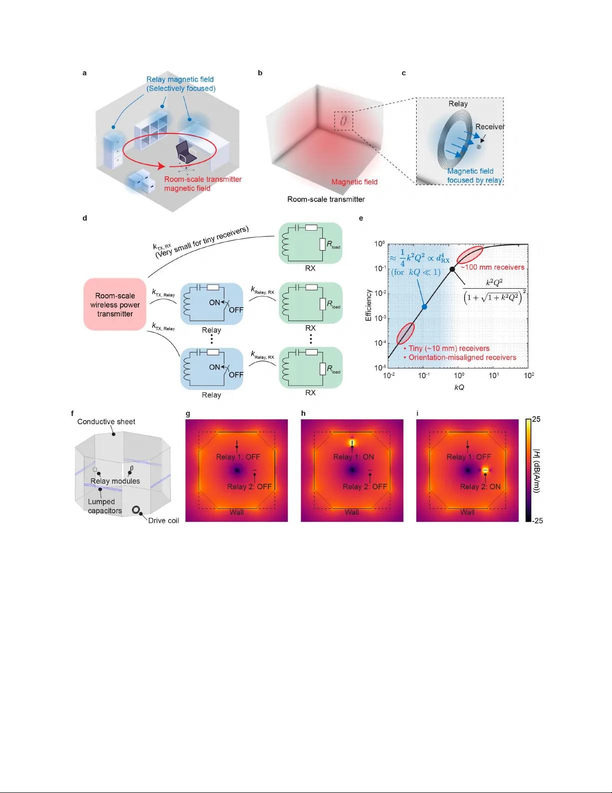
Reconfiguring r oom-scale magnetoquasistatic wireless po wer transfer with hierar c hical resonators T akuy a Sasatani 1,† , Alanson P . Sample 2 , and Y oshihiro Kawahara 1 1 Depar tment of Electrical Engineer ing and Inf ormation Systems, The University of T okyo , T okyo , J apan. 2 Electrical Engineer ing and Computer Science Depar tment, Univ ersity of Michigan, Ann Arbor , USA. † Corresponding author : sasatani@g.ecc.u-tokyo .ac.jp ABSTRA CT Magnetoquasistatic wireless power tr ansfer can deliv er substantial pow er to mobile devices o ver near-field links. Room-scale implementations , such as quasistatic cavity resonators, extend this capability ov er large enclosed v olumes, b ut their efficiency drops sharply for centimeter-scale or misoriented receiv ers because the magnetic field is spatially broad and weakly coupled to small coils. Here , we introduce hierarchical resonators that act as selectively activated rela ys within a room-scale quasistatic cavity resonator, captur ing the ambient magnetic field and re-emitting it to concentrate flux at a target receiver . This architecture reconfigures the wireless power environment on demand and enab les localized energy deliver y to miniature devices. Experimentally , the hierarchical link improves pow er transfer efficiency by more than two orders of magnitude relative to direct room-scale tr ansfer and deliv ers up to 500 mW of DC po wer to a 15 mm receiv er . We fur ther demonstrate selective multi-rela y operation and field reorientation for furniture-embedded charging scenarios. These results estab lish a scalable route to reconfigurable wireless power delivery for miniature and batter yless devices in room-scale environments . Introduction The vision of the Internet of Things (IoT) has been significantly advanced by the dev elopment of ubiquitous sensing systems enabled by wireless communication, but is no w fundamentally constrained by ho w distrib uted electronic de vices are powered 1 – 4 . As we transition tow ard spaces populated by hundreds of miniature sensors and actuators, traditional po wer solutions—wired connections and batteries—pose significant bottlenecks due to frequent manual recharging or battery replacement, as well as their en vironmental impact. Wireless po wer transfer of fers a pathway to untether these devices, yet a critical gap remains: safely and efficiently deli vering po wer to small-scale recei vers across large v olumes 5 . T raditionally , wide-range wireless power solutions rely on radiati ve electromagnetic fields, such as microw av es 6 – 10 . While effecti v e over se veral meters, these approaches require receiv er sizes comparable to the operating wa velength to maintain po wer efficienc y and are fundamentally limited by the significant interaction with biological tissue 11 , 12 . These constraints often result in deliv erable power lev els that are insufficient for many IoT nodes. The use of standing wa ves generated by cavity resonators has been e xplored but f aces similar limitations due to electric field exposure 13 , 14 . Magnetoquasistatic approaches provide a safer , high-power alternati ve 15 – 19 ; because magnetic fields at MHz or lo wer frequencies interact minimally with biological tissue, they allow for significantly higher po wer le vels while remaining within safety limits 20 , 21 . Howe ver , con ventional systems are typically limited to short-range transfer , making charging pads or surfaces the primary use case 5 , 22 . T o extend the range of magnetoquasistatic wireless po wer transfer , room-scale systems based on quasistatic cavity resonators (QSCRs) ha ve emerged as a promising approach 23 – 25 . These structures use conducti ve surfaces and lumped capacitors to generate homogeneous magnetic field patterns that permeate large enclosed v olumes. By confining electric fields to discrete capacitiv e elements, they can deliver tens of watts throughout a room while remaining within established safety guidelines 21 , 23 , 26 . Ho wev er , a fundamental scaling barrier remains: in highly asymmetric systems, power transfer ef ficiency drops sharply as the recei ver size decreases. Prior work extended QSCRs to multimode structures that support multiple magnetic field patterns and improv e cov erage, providing a degree of reconfigurability , but generating localized fields on demand remains challenging 26 , 27 . This scaling challenge is fundamentally rooted in the physics of highly asymmetric coupled-resonator systems. The maximum ef ficiency η max achie vable between a transmitter and recei ver is determined by the dimensionless coupling parameter k √ Q 1 Q 2 , hereafter referred to as the kQ -product, where k is the coupling coefficient and Q 1 and Q 2 are the quality factors of the transmitter and recei ver , respectiv ely 28 . In the weak-coupling regime characteristic of miniature recei vers operating within room-scale transmitters, this relation simplifies to η max ≈ 1 4 k 2 Q 1 Q 2 . Because the coupling coefficient k is proportional to the magnetic flux linkage, and that flux linkage scales with recei ver area A ∝ d 2 RX , where d RX is the recei ver’ s characteristic dimension, the resulting efficienc y η scales as d 4 RX or more steeply . This scaling la w imposes a severe penalty on miniaturization, because the homogeneous fields of room-scale systems lack the spatial localization needed to maintain suf ficient flux linkage for centimeter-scale nodes. Here, we demonstrate a hierarchical resonator architecture that utilizes intermediate relay resonators—acting as local repeaters—to selecti vely reconfigure the room-scale magnetoquasistatic en vironment (Figures 1 a-c). This multiscale interface locally intensifies and reconfigures the magnetic field generated by room-scale transmitters. Integrating these relays into existing en vironmental structures, such as furniture or architectural elements, is particularly ef fectiv e, as furniture layout inherently defines the typical placement and orientation of mobile devices. In this work, we provide e xperimental characterization of this architecture, demonstrating that this hierarchical link increases power deli very effi ciency for pebble-sized recei vers by more than two orders of magnitude ov er direct transfer , delivering up to 500 mW . These hierarchical resonators can be controlled via bistable electronic switches, providing a mechanism for on-demand po wer distribution with minimal power -consumption overhead (Figure 1 d). This system-lev el architectural approach offers a pathway for selectiv e yet ubiquitous power deli very , supporting the deployment of po wer-hungry , small IoT devices in comple x smart en vironments. Results Scaling principle and hierarc hical resonator arc hitecture T o characterize the factors that limit asymmetric wireless po wer systems—from room-scale transmitters to miniature recei vers—we first e xamine the coupling physics gov erning these disparate scales. As illustrated in Figure 1 e, the maximum efficienc y η max achie vable between a pair of resonators with quality factors Q 1 and Q 2 and coupling coef ficient k 1 , 2 is determined by the dimensionless parameter k 1 , 2 √ Q 1 Q 2 (the kQ -product) 28 , 29 : η max = k 2 1 , 2 Q 1 Q 2 1 + q 1 + k 2 1 , 2 Q 1 Q 2 2 (1) The coupling coef ficient k 1 , 2 is physically related to the magnetic flux linkage β through the recei ver and the total magnetic energy stored in the ca vity volume α 13 : k 1 , 2 = β √ 2 L 2 α (2) β = ZZ A 2 µ 0 H 1 · n d A 2 (3) α = ZZZ V 1 µ 0 | H 1 | 2 2 ! d V 1 (4) When the recei ver is much smaller than the transmitter volume, the system operates in the weak-coupling re gime ( kQ ≪ 1). Under this condition, the maximum efficienc y simplifies to η max ≈ 1 4 k 2 Q 1 Q 2 (5) 2/ 12 Because the magnetic field H 1 generated by a room-scale transmitter is approximately uniform across the aperture A 2 of a miniature recei ver , the flux linkage scales directly with area, β ∝ A 2 ∝ d 2 RX , where d RX denotes the recei ver’ s characteristic dimension. Consequently , as shown in Figure 1 e, the ef ficiency scales as d 4 RX or more steeply . This scaling law imposes a se vere penalty on miniaturization: a system capable of deliv ering high efficienc y to mobile- sized ( ∼ 100 mm ) recei vers can fall belo w 0 . 1% ef ficiency when scaled do wn to tiny ( ∼ 10 mm ) or misaligned nodes. This sharp decline fundamentally limits direct po wer transfer to miniature devices. Our hierarchical architecture addresses this constraint by introducing relay resonators that locally concentrate the magnetic field near the recei ver . Reconfiguring the magnetic field with hierar chical resonators The magnetic flux linkage of miniature or misaligned recei vers can be drastically enhanced by locally modifying the field’ s amplitude and v ector orientation. Our approach utilizes relay resonators that “capture” the ambient room-scale magnetic field and re-emit it to achiev e this localized transformation. When these relay modules are activ ated within the charging v olume, energy is partially coupled into the relays, causing them to re-emit a secondary magnetic field. The resulting spatial field is a superposition of the original transmitter field and the intensified localized field of the relay , effecti vely reconfiguring the room’ s homogeneous field pattern into a targeted deli very link. By strategically embedding these relay modules into elements of the built environment, the magnetic field distribution can be selecti vely reconfigured. This approach is pragmatic because furniture and architectural features often determine the placement and orientation of mobile and IoT de vices within a room. A key adv antage of this architecture is that the primary energy source remains the room-scale transmitter , so the relay action itself is passiv e. Furthermore, the relay ef fect can be toggled on demand via electronic switches integrated into the resonator loop. By utilizing bistable components—such as latched mechanical relays 22 —the module requires ener gy only during state transitions and consumes zero static po wer to maintain its activ e state. This enables efficient, on-demand po wer distribution with ne gligible po wer overhead. Figure 1 f-i illustrates the simulated magnetic field patterns generated by this hierarchical approach. Using a 3-D model of a room-scale transmitter b uilt on quasistatic cavity resonance technology 26 , simulations sho w that the field distribution is homogeneous when relays are inacti ve (Figures 1 f-g). This baseline distribution exhibits the nearly uniform magnetic field characteristic of direct power transfer . In contrast, acti vating a relay significantly intensifies the local field in its proximity , while the global field remains nearly stable (Figures 1 h-i). This selective reconfiguration enables ef ficient power transfer to pre viously unreachable recei vers via direct transfer methods. Evaluation of po wer transfer efficiency W e ev aluated the hierarchical wireless po wer system using a 3 m × 3 m × 2 m room-scale transmitter e xcited by a dri ve coil, consistent with the configuration established in prior work (Figures 2 a,b) 26 . The system was operated in the pole-independent (PI) mode because of its broad volumetric cov erage, although the proposed approach is not fundamentally restricted to this mode. T o express relay location in a setup-independent manner, we use the kQ -product of the transmitter–relay link as a position-independent measure of coupling, while receiv er position is specified using a local coordinate system ( x ′ , y ′ , z ′ ) centered on the relay module (Figure 2 c). All resonant components were tuned to a center frequency of 1 . 34 MHz . The relay module consisted of a 150 mm square, 6-turn coil, whereas the recei ver used a 15 mm -diameter , 10-turn coil. The quality factors of the room-scale transmitter , relay resonator , and receiver coil were measured as Q TX = 540 , Q relay = 202 , and Q RX = 53 , respectively 30 . For these initial benchmarks, the relay was acti vated by a direct short connection to e valuate the maximum achie vable relay ef fect. S-parameters between the driv e coil and the 15 mm recei ver were measured using a vector network analyzer (VN A). The maximum po wer transfer efficienc y was then calculated assuming the use of appropriate impedance tuning 23 , 26 , 28 , 31 . Figure 2 d shows the effect of receiver position relativ e to the relay , with the transmitter–relay coupling fixed at a kQ -product of 2. W ithout a relay , the baseline direct-transfer efficienc y remains low at approxi- mately 0 . 3% across the measured range. When the relay is activ ated, the efficienc y increases to more than 20% at a relati ve distance of 50 mm ( z ′ = 0 ). This enhancement persists under vertical misalignment: even at z ′ = 50 mm , the ef ficiency remains well abov e the baseline value. 3/ 12 T o examine the effect of relay placement, Figure 2 e plots efficiency as a function of the transmitter–relay kQ -product, with the recei ver fix ed at x ′ = 100 mm and z ′ = 0 . Although the baseline ef ficiency increases slightly with stronger transmitter–relay coupling because of the stronger ambient field, the relay-assisted link retains a clear performance advantage. The efficienc y increases from approximately 5 . 5% at kQ = 1 to nearly 10% at kQ = 3 . These results sho w that the hierarchical architecture improves transfer ef ficiency across a range of spatial configurations and coupling conditions. Multichannel operation and system thr oughput W e further in vestigated system beha vior in the presence of multiple relay–receiv er pairs, as illustrated in Figure 3 a. T wo relays were positioned at locations corresponding to kQ v alues of 1, 2, and 3 to emulate both balanced and unbalanced coupling scenarios. For each configuration, ef ficiency was e v aluated by switching each relay between ON (short) and OFF (open) states. The results show that activ ating multiple relays simultaneously introduces competition for the ambient room-scale field (Figure 3 b–d). When both relays are activ e (ON, ON), the ef ficiency of each indi vidual link (RX1 and RX2) decreases relati ve to the corresponding single-relay states (ON, OFF and OFF , ON). Even so, the ef ficiency remains substantially abov e the baseline as long as the corresponding relay is activ e. This degradation depends on the relati ve coupling strengths of the transmitter –relay links. In a balanced scenario ( kQ 1 = 2 , kQ 2 = 2 ), both recei vers e xhibit a moderate and nearly symmetric drop in ef ficiency . By contrast, in an imbalanced scenario ( kQ 1 = 3 , kQ 2 = 1 ), the weaker link (RX2) experiences a larger reduction when Relay 1 is acti vated, because the more strongly coupled relay draws a disproportionate share of the transmitter energy . Despite this reduction in indi vidual link ef ficiency , the results suggest that total system throughput—the combined po wer deli vered to all acti ve recei vers—can be improv ed by dynamically controlling the relay states according to de vice requirements and spatial demand. DC-to-DC performance Finally , we characterized the end-to-end DC-to-DC efficienc y and deliv erable output power . The receiv er was integrated with a full-bridge rectifier and tuning capacitors (Figure 4 a) to deliv er power to a 100 Ω DC load. W e define the end-to-end efficienc y as the ratio of the power deli vered to the DC load to the power drawn from the DC source dri ving the RF po wer amplifier . For this characterization, the relay was positioned such that k TX , relay p Q TX Q relay = 2 , while the receiver was fixed at ( x ′ , y ′ , z ′ ) = ( 100 , 0 , 0 ) mm relati ve to the relay . The impedance-tuning circuit was designed to maximize transfer ef ficiency under these conditions, resulting in the network topology sho wn in Figure 4 a. As sho wn in Figure 4 b, the overall DC-to-DC ef ficiency remains approximately constant at 5% ov er a range of input po wer lev els. This is lower than the corresponding A C-to-A C efficienc y , which was approximately 8% under the same spatial conditions, o wing to rectification and con version losses in the transmitter and recei ver stages. The system deli vered up to 500 mW of DC po wer to the load with a 9 W input, demonstrating the feasibility of po wering miniature IoT de vices from a room-scale source through the hierarchical relay architecture. Discussion The hierarchical resonator architecture introduced here addresses the fundamental "coupling gap" inherent in room- scale magnetoquasistatic en vironments. While traditional room-scale systems provide high po wer to mobile-sized recei vers, they are constrained by a d 4 RX ef ficiency scaling that sev erely penalizes smaller nodes. Our results demonstrate that semi-passiv e relay modules can ef fectiv ely bridge this gap, enhancing po wer deliv ery efficienc y by ov er two orders of magnitude and deli vering up to 500 mW to 15 mm recei vers. Demonstration of localized field reconfiguration The utility of the hierarchical link was illustrated through sev eral example deployment scenarios (Figure 5 ). W e demonstrated po wer deliv ery to batteryless microcontrollers and battery-charging circuits submerged in water , highlighting the weak interaction of magnetic fields with dielectric en vironments. This supports power deli very to 4/ 12 of f-the-shelf components without extensi ve lo w-po wer redesign. These relay modules incorporate microcontroller- based control circuits that harv est energy directly from the room’ s magnetic field to po wer their own logic, while bistable mechanical relays are used to switch between operational states without static po wer consumption. Furthermore, we demonstrated a field-bending function based on the same hierarchical system model, in which a relay captures a horizontal cavity field and re-emits it along a v ertical axis (Figures 5 c–e). This mechanism addresses orientation-dependent coupling by enabling po wer deliv ery to misaligned de vices that would otherwise intercept little magnetic flux. W e illustrated this concept by embedding the relay into a wooden shelf, a practical placement strategy because de vices stored on shelv es often hav e constrained orientations. These results suggest that hierarchical resonators can serve as dynamic interf aces for localized wireless power deli very in built en vironments. Future work and limitations Future research will focus on transitioning from manual relay control to autonomous control logic based on real-time recei ver demand and spatial occupanc y . More deeply integrating these resonators into the b uilt environment could enable more seamless wireless power delivery . In addition, understanding the collective behavior and potential mutual interference of large numbers of automatically controlled relays will be essential for scaling this architecture to support hundreds of simultaneous nodes in complex, multi-user smart en vironments. Methods Efficiency characterization The system’ s po wer transfer efficienc y was characterized using tw o-port S-parameter measurements obtained via a vector network analyzer (VN A). The maximum achie vable ef ficiency ( η max ) was calculated from the measured S-parameters 28 . This calculation assumes an appropriately designed tuning capacitor bank, providing a benchmark for the theoretical limit of the hierarchical link. All resonant structures—including the room-scale transmitter , relay modules, and recei ver coils—were tuned to a center frequenc y of 1 . 34 MHz using high-Q capacitors to minimize dissipati ve losses. T o generalize performance across various spatial configurations within the cavity , the kQ -product of the relay-transmitter link was employed as a position-independent metric for coupling strength, extracted directly from S-parameter data. End-to-end measurements DC-to-DC ef ficiency was e valuated by inte grating the receiv er with a full-bridge rectifier . Efficienc y was defined as the ratio of the DC power deli vered to a 100 Ω resisti ve load to the total DC power input to the transmitter drive circuit. Throughput and thermal stability were assessed at input power le vels up to 9 W. For the batteryless node demonstration, an Atmel A Ttiny-series microcontroller equipped with an LED indicator was used to verify functional power deliv ery within the localized intensification zones. The battery-charging demonstration used a linear char ging circuit configured for a constant-current output of 50 mA . The field-bending capability was demonstrated using a smartphone equipped with a custom-designed receiv er coil and a power - management circuit to accommodate v ariable rectified voltages. On the transmitter side, a DC power source (Ke ysight E36312A) supplied power to a high-frequency zero- voltage-switching (ZVS) Class-D po wer amplifier development board (EPC9065). The amplifier output was coupled to the room-scale transmitter via a dri ve coil. In ev aluating system performance, the auxiliary power consumption of the clock source and logic supplies w as excluded, as these represent fixed o verhead rather than transfer-related losses. Accordingly , the DC input to the power stage was treated as the primary system input. The output power deli vered to the load ( R load , Figure 4 a) was recorded using a high-precision digital multimeter . Electroma gnetic field simulation The RF module of COMSOL Multiphysics w as used for the visualization of magnetic field distributions presented in Figures 1 g-i. The magnetic field intensity was computed using the Electromagnetic W a ves, Frequenc y Domain (emw) physics interface. The simulation utilized a frequency domain study to determine the field patterns resulting from a normalized net input po wer of 1 W , defined as the po wer actually accepted by the system ( P inc ( 1 − | S 11 | 2 ) ). 5/ 12 This normalization accounts for the operation of high-ef ficiency switching in verters, where the reflected power does not directly translate into dissipativ e loss as it might in traditional linear amplifiers used in communication studies. These models account for the localized field intensification and reconfiguration provided by the relay resonators within the room-scale cavity en vironment. Use of artificial intellig ence Generati ve AI tools (OpenAI GPT and Google Gemini) were used to refine the language and grammar of the manuscript. References 1. Xu, L. D., He, W . & Li, S. Internet of things in industries: A survey . IEEE T ransactions on Ind. Informatics 10 , 2233–2243, DOI: 10.1109/TII.2014.2300753 (2014). 2. W eiser , M. The computer for the 21 st century . A CM SIGMOBILE Mob. Comput. Commun. Rev. 3 , 3–11, DOI: 10.1145/329124.329126 (1999). 3. Huang, J., Zhou, Y ., Ning, Z. & Ghara vi, H. W ireless Power T ransfer and Energy Harv esting: Current Status and Future Prospects. IEEE W ir el. Commun. 26 , 163–169, DOI: 10.1109/MWC.2019.1800378 (2019). 4. Portilla, L. et al. W irelessly powered lar ge-area electronics for the Internet of Things. Nat. Electr on. 6 , 10–17, DOI: 10.1038/s41928- 022- 00898- 5 (2023). 5. Hui, S. Y ., Zhong, W . & Lee, C. K. A critical revie w of recent progress in mid-range wireless po wer transfer . IEEE T ransactions on P ower Electr on. 29 , 4500–4511, DOI: 10.1109/TPEL.2013.2249670 (2014). ISBN: 0885-8993. 6. Shinohara, N. Po wer Without W ires. IEEE Micr ow. Mag. 12 , S64–S73, DOI: 10.1109/MMM.2011.942732 (2011). 7. Bro wn, W . C. The History of Power T ransmission by Radio W av es. IEEE T ransactions on Microw. Theory T ech. 32 , 1230–1242, DOI: 10.1109/TMTT .1984.1132833 (1984). 8. Strassner , B. & Chang, K. Microwa ve power transmission: Historical milestones and system components. Pr oc. IEEE 101 , 1379–1396, DOI: 10.1109/JPROC.2013.2246132 (2013). 9. Li, W ., Y u, Q., Qiu, J. H. & Qi, J. Intelligent wireless power transfer via a 2-bit compact reconfigurable transmissi ve-metasurface-based router . Nat. communications 15 , 2807 (2024). 10. W ang, X. et al. High-performance cost efficient simultaneous wireless information and power transfers deploying jointly modulated amplifying programmable metasurface. Nat. Commun. 14 , 6002, DOI: 10.1038/ s41467- 023- 41763- z (2023). 11. Garnica, J., Chinga, R. A. & Lin, J. Wireless Po wer Transmission: From Far Field to Near Field. Pr oc. IEEE 101 , 1321–1331, DOI: 10.1109/JPR OC.2013.2251411 (2013). 12. International Commission on Non-Ionizing Radiation Protection, GUIDELINES FOR LIMITING EXPOSURE TO TIME-V AR YING ELECTRIC, MA GNETIC, AND ELECTR OMA GNETIC FIELDS (UP T O 300 GHz). Heal. Phys. 74 , 494 (1998). 13. Chabalko, M. J. & Sample, A. P . Resonant cavity mode enabled wireless power transfer . Appl. Phys. Lett. 105 , DOI: 10.1063/1.4904344 (2014). 14. T amura, M. & Ide, A. Cavity-Resonance-Enabled W ireless Power T ransfer System W ith Compensation for Frequency Fluctuations Caused by Equipment Installation and Its Operation. IEEE J. Micr owaves 6 , 91–99, DOI: 10.1109/JMW .2025.3622603 (2026). 15. Kurs, A. et al. W ireless power transfer via strongly coupled magnetic resonances. Science 317 , 83–86, DOI: 10.1126/science.1143254 (2007). ISBN: 9781479935406. 6/ 12 16. Sample, A. P ., Meyer , D. A. & Smith, J. R. Analysis, experimental results, and range adaptation of magnetically coupled resonators for wireless power transfer . IEEE T ransactions on Ind. Electr on. 58 , 544–554, DOI: 10.1109/TIE.2010.2046002 (2011). 17. Assaw aworrarit, S. & Fan, S. Robust and ef ficient wireless power transfer using a switch-mode implementation of a nonlinear parity–time symmetric circuit. Nat. Electr on. 3 , 273–279, DOI: 10.1038/s41928- 020- 0399- 7 (2020). 18. Song, M. et al. W ireless po wer transfer based on novel physical concepts. Nat. Electr on. 4 , 707–716, DOI: 10.1038/s41928- 021- 00658- x (2021). 19. Chen, Y ., Niu, S., Fu, W . & Lin, H. Modelling of ne gativ e equiv alent magnetic reluctance struc- ture and its application in weak-coupling wireless power transmission. Nat. Commun. 15 , 6135, DOI: 10.1038/s41467- 024- 50492- w (2024). 20. Christ, A., Douglas, M., Nadakuduti, J. & Kuster , N. Assessing human exposure to electromagnetic fields from wireless po wer transmission systems. Pr oc. IEEE 101 , 1482–1493, DOI: 10.1109/JPR OC.2013.2245851 (2013). 21. Hirata, A. et al. Electromagnetic Field Exposure Assessment and Mitigation Strategies for W ireless Power Trans- fer Systems: A Revie w and Future Perspectives, DOI: 10.48550/arXi v .2510.18570 (2025). [physics]. 22. Sumiya, K. et al. Alvus: A Reconfigurable 2-D Wireless Char ging System. Pr oc. A CM on Interactive , Mobile, W earable Ubiquitous T echnol. 3 , 1–29, DOI: 10.1145/3332533 (2019). Journal. 23. Chabalko, M. J., Shahmohammadi, M. & Sample, A. P . Quasistatic cavity resonance for ubiquitous W ireless po wer transfer . PLoS ONE 12 , 1–14, DOI: 10.1371/journal.pone.0169045 (2017). 24. Sasatani, T ., Chabalko, M., Kawahara, Y . & Sample, A. Geometry-Based Circuit Modeling of Quasi-Static Cavity Resonators for W ireless Power T ransfer. IEEE Open J. P ower Electron. 3 , 382–390, DOI: 10.1109/ OJPEL.2022.3183600 (2022). 25. Sasatani, T ., Y ang, C. J., Chabalko, M. J., Kawahara, Y . & Sample, A. P . Room-W ide Wireless Charging and Load-Modulation Communication via Quasistatic Ca vity Resonance. Proc. A CM on Interactive, Mobile, W earable Ubiquitous T echnol. 2 , 1–23, DOI: 10.1145/3287066 (2018). 26. Sasatani, T ., Sample, A. P . & Kawahara, Y . Room-scale magnetoquasistatic wireless power transfer using a cavity-based multimode resonator . Nat. Electr on. c , DOI: 10.1038/s41928- 021- 00636- 3 (2021). Publisher: Springer US. 27. Sasatani, T ., Chabalko, M. J., Kawahara, Y . & Sample, A. P . Multimode Quasistatic Cavity Resonators for W ireless Power Transfer. IEEE Antennas W ir el. Pr opag. Lett. 16 , 2746–2749, DOI: 10.1109/LA WP .2017. 2744658 (2017). 28. Zargham, M. & Gulak, P . G. Maximum achiev able effi ciency in near-field coupled po wer-transfer systems. IEEE T ransactions on Biomed. Cir cuits Syst. 6 , 228–245, DOI: 10.1109/TBCAS.2011.2174794 (2012). ISBN: 19324545 (ISSN). 29. Haus, H. A. & Huang, W . Coupled-Mode Theory. Pr oc. IEEE 79 , 1505–1518, DOI: 10.1109/5.104225 (1991). ISBN: 0018-9219. 30. Kajfez, D. & Hwan, E. Q-Factor Measurement with Network Analyzer. IEEE T ransactions on Micr ow. Theory T ech. 32 , 666–670, DOI: 10.1109/TMTT .1984.1132751 (1984). 31. Sample, A. P ., W aters, B. H., W isdom, S. T . & Smith, J. R. Enabling seamless wireless power delivery in dynamic en vironments. Pr oc. IEEE 101 , 1343–1358, DOI: 10.1109/JPR OC.2013.2252453 (2013). ISBN: 0018-9219. 7/ 12 Data av ailability The data that support the findings of this study are av ailable at Zenodo ( DOI: 10.5281/zenodo.19287419 ) and in the project repository ( GitHub ). Code av ailability The code that supports the findings of this study is av ailable at Zenodo ( DOI: 10.5281/zenodo.19287419 ) and in the project repository ( GitHub ). Competing interests The authors declare no competing interests. Ackno wledg ements This work was supported by JST FOREST (Grant Number JPMJFR242P), JST ACT -X (Grant Number JPM- J AX190F), and JSPS KAKENHI (Grant Number 23K28068). A uthor contributions T .S. designed the research, conceiv ed the experiments, analyzed the results, and wrote the manuscript. All authors re viewed and re vised the manuscript. 8/ 12 Figure 1. Concept of hierarchical resonators f or wireless power transfer . a Illustration of a representati ve deployment scenario. The room-scale transmitter generates a wide-area magnetic field, while objects in the interior can embed relay modules that form hierarchical links and selectively focus the magnetic field. b, c Illustration of the field-focusing ef fect, in which intermediate relay resonators selectively concentrate and redirect magnetic flux from the room-scale transmitter to miniature recei vers. d Schematic representation of the hierarchical coupling architecture. Because direct coupling between the transmitter and the tiny recei vers ( k TX , RX ) is very weak, hierarchical links can be used to enhance po wer transfer efficienc y . e Relationship between the k Q -product and po wer transfer efficiency . The plot illustrates representative operating points for standard ( ∼ 100 mm ) receiv ers and tiny ( ∼ 10 mm) or orientation-misaligned receiv ers. In the extremely weak-coupling regime, the ef ficiency scales approximately as d 4 RX , where d RX is the characteristic dimension of the recei ver . f Three-dimensional model of the cavity resonator used in this study . The transmitter uses conductiv e sheets with integrated lumped capacitors to generate a magnetic field while confining electric fields. g T op-do wn view of the baseline magnetic field distrib ution, sho wing a homogeneous field pattern. h, i Reconfigured field distributions with Relay 1 and Relay 2 acti vated, respecti vely . The localized amplification of the magnetic field near the relay modules illustrates the ability to selecti vely direct po wer within large spaces. 9/ 12 Figure 2. Experimental setup for efficiency measur ements. a Photograph of the room-scale quasistatic cavity resonator used in this study 26 . b Interior view of the furnished ca vity , showing the dri ve coil and a representati ve relay–recei ver measurement arrangement. c Detailed view of the relay module and miniature receiver , together with the local coordinate system used to define recei ver position relati ve to the relay . d Power transfer ef ficiency as a function of the distance between the relay and recei ver for two v ertical offsets ( z ′ = 0 and z ′ = 50 mm), compared with the baseline direct-transfer case. e Power transfer ef ficiency as a function of the transmitter–relay kQ -product, sho wing a substantial improvement of the hierarchical relay link o ver baseline direct transfer . 10/ 12 Figure 3. Multi-relay reconfigurability . a Schematic of a room-scale transmitter supporting two hierarchical links, from Relay 1 to RX1 and from Relay 2 to RX2. b–d Measured power transfer ef ficiency of RX1 and RX2 for the four relay states (OFF , OFF), (OFF , ON), (ON, OFF), and (ON, ON) under different transmitter –relay k Q configurations. The results show ho w simultaneous relay activ ation redistributes po wer between the two links depending on their relati ve coupling strengths. Figure 4. Rectified power performance and o verall efficiency . a Circuit schematic of the miniature receiver , including the resonant coil ( L RX ), tuning capacitors, and a full-wa ve bridge rectifier . b Measured output power and ov erall DC-to-DC efficienc y as functions of input power . The system deliv ers up to 500 mW of rectified output po wer while maintaining an overall ef ficiency of approximately 5%. 11/ 12 Figure 5. Demonstrations and usage scenarios of hierarchical resonators. a Localized power deli very to a batteryless microcontroller unit (MCU) with an LED indicator . b Charging a Li-Po battery in water , illustrating the weak interaction of magnetic fields with dielectric en vironments. c A field-bending relay module embedded in a wooden shelf, designed to capture the horizontal room field and re-emit it as a v ertically reoriented field. d, e Smartphone charging demonstration sho wing the transition from no charging with the relay OFF ( d ) to acti ve charging with the relay ON ( e ) through field reconfiguration. 12/ 12
Original Paper
Loading high-quality paper...
Comments & Academic Discussion
Loading comments...
Leave a Comment