Joint Training Scattering Matrix Learning and Channel Estimation for Beyond-Diagonal Reconfigurable Intelligent Surfaces
Beyond-diagonal reconfigurable intelligent surface (BD-RIS) generalizes the conventional diagonal RIS (D-RIS) by introducing tunable inter-element connections, offering enhanced wave manipulation capabilities. However, realizing the advantages of BD-…
Authors: Yiyang Peng, Binggui Zhou, Yutong Zheng
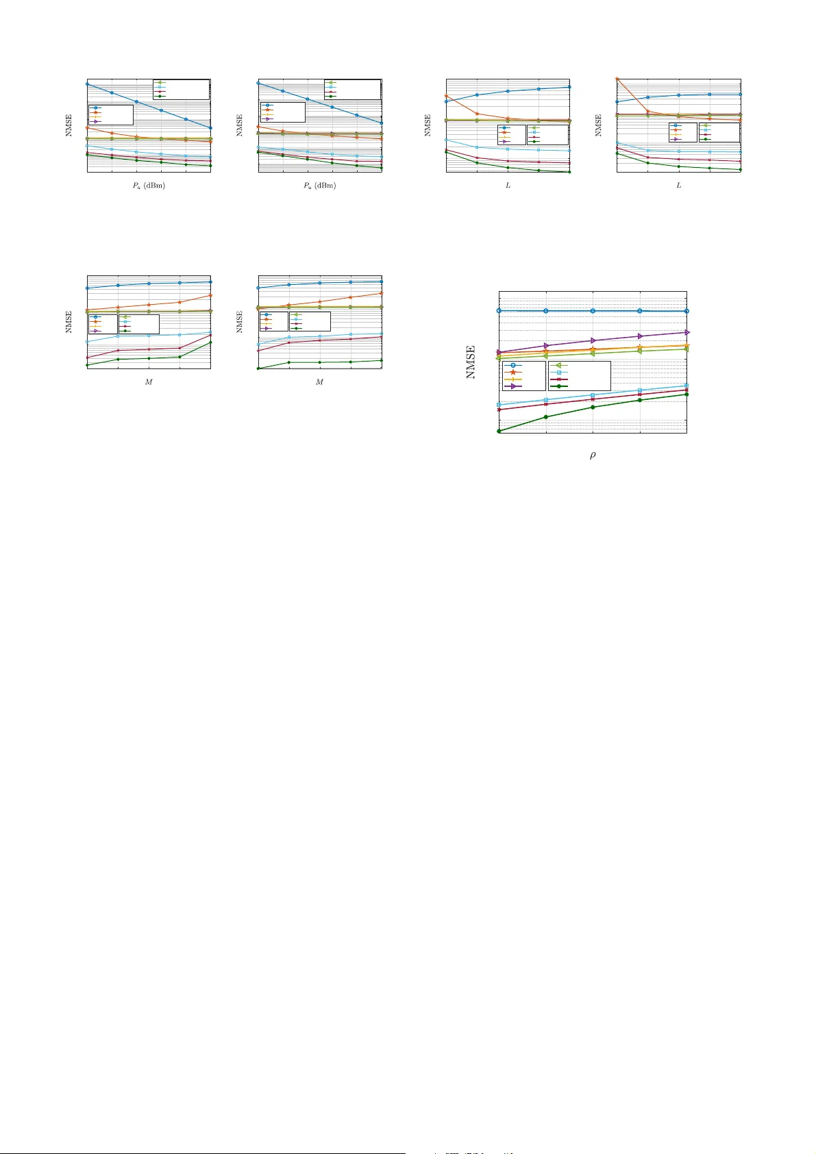
1 Joint T raining Scatter ing Matrix Learning and Channel Estimation for Be yond-Diagonal Reconfigurable Intelligent Surfac es Y iya ng Peng, Binggui Zhou, Y utong Zheng, Danilo Mand ic , and Bruno Cle rck x Abstract —Bey ond-diagonal reconfigurable intelligent surface (BD-RIS) generalizes the con v entional diagonal RIS (D-RIS) by introducing tunable inter-eleme nt connections, offering enhanced wa ve manipu lation capabilities. Ho wev er , realizing the adva n- tages of BD-RIS requires accurate channel state information (CSI), whose acquisition becomes signi ficantly more challenging due to t h e increased number of channel coefficients, leading to pro hibitively large pilot trainin g overhead in BD-RIS- aid ed multi-user multiple-input mu ltiple-outpu t (MU-MIMO) systems. Existing studies reduce pilot overhead by exploiting the chann el correla tions induced by the Kronecke r -product or multi-linear structure of BD-RIS-aided channels, which neglect the spatial correla tion among antennas and the statistical correlation across RIS-user ch annels. In this paper , we pro pose a learning-based channel estimation framework, namely the join t t raining scatter - ing matrix learning and chan n el esti mation framework (JTSML- CEF), wh ich jointly optimizes the BD - RIS trainin g scattering matrix and estimates the cascaded channels in an end-to-end manner to achi ev e accurate channel estimation and reduce the pilot overhea d. The p roposed JTSM LCEF follows a two-phase channel estimation pr otocol to e nable adaptiv e training sca ttering matrix optimization with a trainin g scattering matrix optimizer (TSMO) and cascaded chann el estimation with a dual-attention channel estimator ( DA CE) . Sp ecifically , the D A CE is designed with intra-user and inter-user atten t ion modules to capture the multi-dimensional correlations in mult i -user cascaded channels. Simulation results demonstrate the superiority of JTSM LCEF . Compared with the current state-of-the-art method, it reduces the p ilot overhead by 80% while fu rther reducing the normalized mean squ ared error (NM S E) by 82 . 6% and 92 . 5% in indoor and urban micro-cell (UMi ) scenarios, respectiv ely . Index T erms —Beyo nd-diagonal reconfigurable intell igent sur- face (BD- RIS), low-o verhead channel estimation, traini ng scat- tering matrix learning, deep learning. I . I N T R O D U C T I O N Beyond-diag o nal reconfigu rable intelligent surface (BD- RIS) repr esents a n advanced RIS techniq ue, which generalizes and extends conventional diagon al RIS (D-RIS) [ 1]–[3 ], by enabling reco nfigurab le inter-element conn ections am ong RIS elements via a multipo rt reconfig urable impeda n ce network [4], [5]. Com pared to D-RIS, tunable inter-element con nec- tions in tr oduce new d egre es o f freedo m fo r BD-RIS, enabling smarter wa ve man ipulation, broad er coverage, and better perfor mance acro ss a variety of comm u nication p erform a nce metrics an d wireless app lications [ 4], [5 ] . Y iyang Peng, Binggui Zhou, Y utong Zheng and Danilo Mandic are with the Departmen t of Electrica l and Electronic Engineering, Imperial Colle ge London, London SW7 2AZ, U.K. (e-mail: { yiyang.pe ng22;binggui.zhou;yutong.zheng120;d.mandic } @imperial.ac.uk). Bruno Clerckx is with the Department of Electric al and Electronic Engi- neering , Imperial Colle ge London, London SW7 2AZ, U.K., and also with Ky ung Hee Uni versity , Seoul, Kore a (e-mail: b .clerckx@impe rial.ac.uk) . Motiv ated by the se advantages, extensi ve research has been condu c te d to explore th e ben efits o f BD-RIS from m ultiple perspectives, in cluding architectur e design [6]–[ 9 ], operating mode analysis [10]–[ 12], optimizatio n and performa n ce analy- sis [13] – [15], an d h a r dware impairm ents [1 6]–[2 2]. Howe ver , it shou ld be no te d tha t the p e rforma n ce gains offered by BD- RIS critically de p end on accurate ch annel state info rmation (CSI). Unlike D-RIS, th e circuit top ology of BD-RIS requir e s part of/all scattering elements to be jointly tuned rather th an indepen d ently tuned. As a result, existing cascad ed ch annel estimation methods d ev e lo ped for D-RIS ca nnot be d irectly applied to BD-RIS. Moreover, the inter-element c o nnection s of BD-RIS significantly increase the number of effecti ve channel co efficients, leadin g to substantially h igher training overhead in cascaded chan nel estimation comp ared to D - RIS. The motiv ation of this w ork is twofold. First, base station (BS)-RIS-user cascad ed c h annels in BD-RIS-aided multi-user multiple-inp ut multiple- output ( MU-MIMO) sy stems exhibit strong intra-user and inter-user correlatio ns. Specifically , intr a- user cor relations arise f rom the common BS-RIS channel in the Kro necker-product stru cture o f the cascaded channel and f r om spatial de penden cies amon g transmit an d receive antennas, while inter-user correla tio ns arise from the statistical correlation s among RIS-user chann els acro ss different u ser s and the sha r ed BS-RIS ch a nnel. Ex p loiting these correlation s can sign ificantly red uce th e nu mber of indepe n dent ch annel coefficients, thereby reducin g the pilot overhead. Besides, these correlatio ns ind uce rich feature pattern s in the cascaded channels that can be effectively learned by deep lear ning- based m ethods to en hance ch annel estimation accuracy . Al- though the channel estimation design in [23] is optimal in terms of minimizin g mean squared error (MSE) un der the least squ are (L S) estimator, it treats the cascaded c hannel coefficients as in d epende nt unkn owns, witho ut considering the co rrelations of cascaded ch annels, ind ucing a large p ilot overhead an d limited prac tica l applicability . Sev e r al mod el- driven app r oaches have b e e n pr oposed to reduce the training overhead by exploiting channe l cor relations. In [2 4], an ex- plicit channel corre la tio n m o del indu ced by the Kron e c ker- produ ct structur e is used . T ensor-based methods [ 25]–[ 27] exploit the multi-linear structure of BD-RIS-aided channels throug h tensor decom position. Howe ver, these mod el-driven approa c h es exhibit several limitations. In p articular, [25], [27] consider only single-u ser systems, [2 6 ] neglects inter-user co r- relations, and all of them [24]–[27] do no t exploit the spatial correlation s among transmit/receive antennas and statistical correlation s amo ng RIS- user chann el acr oss users. In addition , the method in [2 4] relies on a seq uential estimation pro cedure, where subsequen t chann e l coefficients are estimated based on previously estimated refer ence channe ls, ther e by introdu cing estimation err o r propag ation. Mor eover , tensor deco m position methods [2 5]–[2 7] rely on iterative op timization as well as explicit r ank or id entifiability assump tio ns, lead ing to com- putational inefficiency and sensitivity to m odel mismatch in dynamic scattering en viron ments. By contrast, recent advances in deep learnin g -based ch an- nel estimation h av e dem onstrated that deep n eural networks (DNNs) can effecti vely learn comp lex c h annel ch aracteristics by implicitly and adap tiv ely exploitin g the mu lti- dimensiona l correlation s of wireless chann e ls in ma ssive MIMO systems [28] a n d captu ring inter-user interactions in D-RIS-aided systems [29], sho win g improved estimation accuracy and reduced pilo t overhead. Additionally , learning-based channel estimation methods d o no t req uire iterative optimization af- ter on line d eployment, which is c omputatio nally efficient in practice. As such, it is p romising to inves tigate learning - based channel estimation to e xploit th e m ulti-dimen sional channel co rrelations in BD-RIS-aided M U-MIMO systems f or accurate cha nnel estimation and reduced p ilot overhead. Second, the design of training patter ns plays an important role in imp roving chann el estimation accuracy fo r RIS-aid e d systems. In most D-RIS ch annel estimation works [30] , [31], training reflectio n patter ns are orthog o nality-ba sed d esigns under g eneral channel m o dels [29] a n d structure d cha n nel models [32], in order to minimize the c h annel estimation error . H owever , such training pattern desig ns for D-RIS cannot be dir e ctly extended to BD-RIS due to different p hysical constraints imposed by the reconfigu rable imped ance n etwork. A f ew work s hav e inves tigated training p a ttern design f o r BD- RIS chann el estimation [23 ], [ 25], [27] , all of wh ich adop t orthog onality-b ased designs d ev e loped under the assumptio n of a no n-recipr ocal imped a nce network. Howe ver, in practice, the recon fig urable im p edance n etwork is typically reciproc al, since realizing no n -recipr o cal n e twork s requires embeddin g non-r eciprocal circu its, wh ich is often cost-inefficient an d impractical in real deploymen ts. Recipro city further imposes an add itional physical constrain t on BD-RIS, which m athemat- ically results in a symm etric scatterin g m a trix. Co n sequently , existing orthog o nality-ba sed training designs developed fo r non-r eciprocal BD-RIS are n o lon ger app licable. M oreover , the symmetry constrain t restricts the feasible training p attern space, thereby complicating the trainin g patter n design for reciproca l BD-RIS. As a resu lt, the design of effectiv e training patterns fo r chann e l estimation in recipro cal BD-RIS remains an o p en p roblem . Based o n these mo tivations, in this work, we pro pose a learning- based ch annel estimation framework for BD-RIS- aided MU-MIMO systems, nam ely the joint training scattering matrix lear n ing an d chann el estimation f ramework (JTSML - CEF), to jointly o ptimize th e BD-RIS training scatter in g matrix and estimate the cascaded chann els in an end-to- end man ner, in ord er to achieve accurate chann el estimation and reduce the p ilot overhead. Unlike existing mode l- driven approa c h es in [24]– [27], the propo sed JTSMLCEF exploits multi-dimen sional chan nel co rrelations withou t estimation er- ror propaga tio n o r rely ing o n real-time iterative op timization proced u res. T h e main contributions o f this work are summ a - rized in the fo llowing. • W e e xploit the structur e of effectiv e ch annel under reciproca l grou p-con nected BD-RIS to r e formula te the cascaded chann el by combin ing chan nel coefficients that share the same scattering coefficients. T his leads to an equiv alent reduced- c oefficient r eformu lation o f the cascaded ch a n nel, significantly r e ducing the numb er o f channel coefficients th at need to be estimated. I n con - trast, existing BD-RIS ch annel estimation works either assume non- reciproc a l BD-RIS a r chitectures or neglect this structur al prope rty of th e effecti ve ch annel. • The proposed JTSMLCEF follows a two-phase channel estimation pr otocol tailored for time division dup lexing (TDD) BD-RIS-aided systems, enabling adaptive training scattering matrix design and up lin k chann el estimation within each c h annel coh erence block. Spec ifically , th e uplink training p r ocess consists of Phase I for optimizing the scattering matr ix fro m rec e ived pilot observations with a training scatterin g matrix o ptimizer (TSMO), a n d Phase II for cascaded cha nnel estima tio n with a dual- attention chann e l estimator (DA CE) using the o ptimized scattering matrices. Unlike most existing D-RIS and BD- RIS training pro to cols that dev o te a ll training slots to channel e stima tion with fixed ch annel-ind epende nt train- ing pattern s, the propo sed two-ph ase protoc ol allocates a small po rtion o f the train in g slots to o p timize th e scat- tering matrices first. This enables a chan nel-dep e n dent training pattern design that is d ynamically adapted to instantaneou s chann el con ditions, th ereby significantly improving estimation efficiency . • T o min imize the estimatio n er ror an d ad dress th e ch al- lenge of incorp o rating unitary an d symme tr ic con straints of the scatter ing ma trix, we design the TSMO to op timize the training susceptanc e m atrix and convert it into a feasible trainin g scattering matrix. Me a n while, to exp lo it both intra-user and inter-user correlatio ns inherent in multi-user cascaded BD-RIS chan nels, we prop ose the D ACE architecture with two novel intra- an d in ter-user attention modu les b ased on the multi-head self-attentio n (MHSA) mec hanism [33 ] . By jointly learning the training scattering matr ix via the TSMO and the in tra- and inter- user dimension features via the DA CE in an end-to - end fashion, the pro posed JTSMLCEF achieves high estimation acc u racy with significantly low pilot overhead. • W e present simulation results to verify the e ffectiveness of the proposed JTSMLCEF using QuaDRiGa chann el model. In b oth indo o r and urban micro - cell (UMi) scenar- ios, JTSMLCEF consistently ach iev es the lowest norm a l- ized mean squared err or (NMSE) acr oss various uplink transmit power le vels, nu mber of RIS elem e nts, and training time slots, compared with th e L S method , model- driven ap proach in [2 4] and d eep-learn in g b aselines. In addition, we test th e prop o sed framework trained on th e UMi dataset u sin g mixed indo or a nd UMi chan nel sam - ples. The JTSMLCEF c ontinues to ou tperfor m all other schemes, demo n strating robustness again st p ropaga tion scenario mismatch . Or ga n ization: Section I I introd uces the system model. Sec- tion I II presen ts the propo sed two-p hase chann el estimation protoco l. In Section IV, we intro duce the training scattering matrix lea r ning and dual-atten tion channel estimation in detail. Section V pr ovides simulation results that verify the effec- ti veness of JTSMLCEF and comp are its perf ormance with baseline metho ds. Finally , Sec tion VI concludes this work. Notations: Non-b old letters, b oldface lowercase letters, boldface upper case letters, and under lined b oldface upp ercase letters represent scalars, column vectors, ma tr ices, and tensors, respectively . [ a ] i and [ A ] i,j denote the i -th entry o f a an d the ( i, j ) -th entry of A , re spectiv ely . [ A ] i : i ′ , j : j ′ represents a submatrix o f A f ormed by extractin g the i -th to i ′ -th rows and j -th to j ′ -th co lumns. Similarly , [ A ] i : i ′ , j : j ′ , k : k ′ denotes a sub - tensor of A formed by the specified index ranges alo ng the first, secon d, and third d imensions, respectively . This notation naturally extends to higher-order ten sors. R and C d enote the set of real numb ers and complex numb ers, respectively . ℜ{·} and ℑ{·} take the real an d ima ginary parts o f the input, respectively . ( · ) T , ( · ) H , and ( · ) − 1 represent transpo se, con - jugate transpose, and inverse o peration s, r espectively . ⊗ and ⊙ represent th e Kr onecker pr oduct and Hadam ard pro duct, respectively . |·| , k·k 2 and k·k F denote the ab solute-value nor m, the ℓ 2 norm, and the Frob enius norm , re sp ectiv e ly . vec ( · ) is the vectorization of a matrix , and vec ( · ) d enotes the reverse operation of vecto rization. I M denotes an M × M iden tity matrix. Finally , = √ − 1 repr esents the ima ginary u nit. I I . S Y S T E M M O D E L W e consider a narrowband BD-RIS- aided MU-MIMO sys- tem workin g in the TDD mod e. As shown in Fig. 1, the system consists of a BS equipp ed with N anten nas, an M -element BD-RIS, an d K users, each equipp ed with U antennas. Th e M -element BD-RIS is a passive device mo deled as M scattering elem ents conne cted to an M -port reco nfig- urable impedance network [6]. Th is reconfig urable n e twork comprises a n umber of tunable c o mpon ents and can be mathematically char acterized by its scatterin g matrix . The BS controls the BD-RIS throug h an RIS co ntroller that ad justs the tunable comp onents of the reco nfigurab le im pedance network to steer the re flec te d signals tow ard d esired direc tio ns. A. Channel Model W e assume a qua si-static blo ck-fading channel model in which the chan nel rem ains appro ximately constant within each cohe r ence blo c k but varies from block to b lock. During the uplink trainin g phase, pilot signals are transmitted, an d the resulting chan nel estimates are su b sequently used for downlink data transmission. In the u plink pilot transmission, the effectiv e cha n nel H eff , k ∈ C N × U between each user k and the BS is expressed as 1 H eff , k = H RT ,k + H I T ΦH RI ,k , ∀ k ∈ K = { 1 , 2 , . . . , K } , (1) where H RT ,k ∈ C N × U , H RI ,k ∈ C M × U and H I T ∈ C N × M denote the d irect user-BS, user-RIS, and RIS-BS ch a n nels for user k , respec tively , an d Φ ∈ C M × M is the u plink scattering matrix . In this work , we assume that the dire c t user-BS ch annels H RT ,k , ∀ k ∈ K , are blocked an d focus o n estimating th e cascaded user-RIS-BS chann els 2 . The uplink 1 W e adopt commonly used channe l modeling assumptions between the BS, BD-RIS, and users, including perfec t anten na matchi ng, no mutual coupling , unilat eral approximation, and no structura l scatteri ng [34]. 2 When the direct user-BS channels e xist, the y can be estimated by first turning of f the RIS and appl ying con ventiona l MU-MIMO channel estimati on methods; their contributi ons can then be subtracted from the recei ved signals. H IT H RI,1 User 1 User 2 User K H RI,2 H RI,K Blockage RIS Controller Base Station I T BD-RIS Z 1,1 Z 2,2 Z 3,3 Z 1,2 Z 2,3 Z 1,3 Antenna 2 Antenna 3 Antenna 1 Group-Connected Architecture with G roup size 3 ... Fig. 1. A BD-RIS-aide d MU-MIMO communication system. effecti ve channel between user k and BS is then g iv e n by H eff , k = H I T ΦH RI ,k = vec ( Q k vec ( Φ )) , (2) where Q k = H T RI ,k ⊗ H I T ∈ C N U × M 2 denotes the uplink cascaded user-RIS-BS chann e l for user k . In [23 ], it has bee n shown that in TDD systems, th e u plink cascad ed ch a n nel Q k , ∀ k ∈ K , estimated fr om uplin k training , can be dire c tly used for downlink data transm ission by utilizing the u plink- downlink recip rocity o f H I T and H RI ,k , ∀ k ∈ K . Dependin g on the circuit to pology of th e M -port r e con- figurable impeda n ce ne twork , v ar ious BD-RIS architectures have been propo sed in the literatu re [6] –[8]. In this work, we fo c us on the gro up-co n nected architecture of BD-RIS [ 6]. For the grou p-con n ected BD-RIS, the M -port reconfigurab le impedanc e network is unifo rmly d ivided into G gro ups, with each group co ntaining ¯ M = M G elements, ref erred to as the group size. Fig . 1 illustrates a 36-element BD-RIS with a group -conne cted architectu re of group size 3 , where one group is highlig hted fo r illustration. Physically , the po rts within the same group are m utually connected via tunable com p onents, e.g., Z 1 , 2 , Z 1 , 3 and Z 2 , 3 in Fig. 1, whereas po rts belong ing to different group s are not connected. Ma th ematically , a group- connected BD-RIS exhibits a b lock-diag onal scatter ing m atrix Φ , written as Φ = blkdia g ( Φ 1 , Φ 2 , . . . , Φ G ) , (3) where each bloc k Φ g ∈ C ¯ M × ¯ M , ∀ g ∈ G = { 1 , 2 , . . . , G } , represents the scattering behavior of group g . In th is work, we assume th a t the recon fig urable imped ance network is lossless and recipro c a l, which lead s to eac h block Φ g being unitary and symm e tric, i.e. , Φ H g Φ g = I ¯ M , Φ T g = Φ g , ∀ g ∈ G . (4) B. A Reduc e d-Coefficient Reformulation of the Cascade d Channel Under the grou p-conn ected BD-RIS arch itecture, effecti ve channel in (2) ca n be equivalently rewritten as H eff , k = X g ∈G H I T ,g Φ g H RI ,k,g = vec X g ∈G ˜ Q k,g φ g , (5) where H I T ,g = [ H I T ] : , ( g − 1) ¯ M +1: g ¯ M ∈ C N × ¯ M , H RI ,k,g = [ H RI ,k ] ( g − 1) ¯ M +1: g ¯ M , : ∈ C ¯ M × U , de noting the g -th block of H I T and H RI ,k , respectively , φ g , vec ( Φ g ) ∈ C ¯ M 2 × 1 , ∀ g ∈ G , deno tin g the g -th bloc k of vectorized BD-RIS scattering matrix, an d ˜ Q k,g , H T RI ,k,g ⊗ H I T ,g ∈ C N U × ¯ M 2 , ∀ g ∈ G , ∀ k ∈ K , (6) denoting the g - th g roup of the uplin k cascad ed chan nel f o r user k . W ith the sym metric c onstraint imposed on Φ g , ∀ g ∈ G , each pair of u p per- and lower -triangu lar en tries of Φ g shares the same scatterin g coefficients. As a re sult, the co rrespond ing cascaded chan nel co e fficients in ˜ Q k,g , ∀ g ∈ G , ∀ k ∈ K , cannot be identified individually from the observations; on ly their co mbined contribution is identifiable. This moti vates us to estimate only the summ ation of ch annel coefficients that share th e same scattering coefficients by rewriting each φ g as φ g = P ¯ φ g , where ¯ φ g ∈ C ¯ M ( ¯ M +1) 2 × 1 collects the diagonal and upper-triangu la r en tr ies o f Φ g , and P ∈ { 0 , 1 } ¯ M 2 × ¯ M ( ¯ M +1) 2 is a b inary matrix mapping ¯ φ g to φ g , ∀ g ∈ G . The explicit fo r m of P is g iven in the Appendix of [21 ]. Th e effecti ve chann e l in (5 ) can thus b e fur ther rewritten as H eff , k = vec X g ∈G ˜ Q k,g P ¯ φ g , = vec X g ∈G ¯ Q k,g ¯ φ g = vec ¯ Q k ¯ φ , (7) where ¯ φ = ¯ φ T 1 , ¯ φ T 2 , . . . , ¯ φ T G T ∈ C M ( ¯ M +1) 2 × 1 , and ¯ Q k = ¯ Q k, 1 , ¯ Q k, 2 , . . . , ¯ Q k,G ∈ C N U × M ( ¯ M +1) 2 , (8) with ¯ Q k,g , ˜ Q k,g P ∈ C N U × ¯ M ( ¯ M +1) 2 , ∀ g ∈ G , ∀ k ∈ K . (9) From (7), we observe that it is sufficient to estimate ¯ Q k,g rather than ˜ Q k,g , ∀ g ∈ G , f o r charac terizing H eff , k , ∀ k ∈ K . According ly , ¯ Q k represents an equivalent c ascaded chan nel for user k . W ith the reformulation in (7), the cha nnel c o effi- cients in ˜ Q k,g , ∀ g ∈ G , co rrespon ding to distinct scattering coefficients are p r eserved in ¯ Q k , while those sharing the same scattering coefficients are com b ined. As a result, ¯ Q k serves as a redu ced-coe fficient reform ulation of the origina l cascaded channel, wh ich r e d uces the total nu mber of channel co e ffi- cients to b e estimated pe r user fro m N U M 2 to N U M ( ¯ M +1) 2 . Nev ertheless, ev e n after exp lo iting the symm etry and block - diagona l structure s of th e scattering matrix, the n umber of coefficients to be estimated in BD-RIS-aided chann els remain s prohib iti vely large. Fro m (6), (8), and (9), it can be ob ser ved that stron g structural depen d encies exist b o th within each ¯ Q k and a c ross ¯ Q k of d ifferent u sers, owing to their blo c k Kronecker structu res. Specifically , each ¯ Q k,g is fo r med by the com bination of H RI ,k,g and H I T ,g , where all antennas of H RI ,k,g share the sam e H I T ,g , ∀ g ∈ G . As a resu lt, the channel coefficients in each ¯ Q k exhibit strong de p endenc ie s along both rows and co lumns, as well as across different users. Moreover , the multiplicatio n b y the binary matr ix P in (9) preserves these structu ral depend encies. These observations motiv ate us to d esign a learning -based cha nnel estima tio n scheme th at can e ffectively exploit these c o rrelations to achieve accurate ch a n nel estimation with significan tly reduced pilot overhead . Remark 1: The reduced -coefficient r e formula tio n in (9) is applicable to a ny BD-RIS architectur es whose scattering matrices are symme tr ic and b lock-d iag onal 3 . F or examp le, in fo r est-connec ted ar chitectures [7], each Φ g is still a f ull matrix, so the same mapping m atrix P can b e used. I I I . T W O - P H A S E C H A N N E L E S T I M A T I O N P ROT O C O L In this section , we de scr ibe the pilot transmission procedu re and the two-ph ase chann el estimation pr o tocol tailored to the propo sed JTSMLCEF . A. Overall Descriptio n of the T wo-Phase Pr otocol T o ensure that th e designed trainin g pattern effecti vely assists chan n el estimation, bo th the scattering matrix de sign and c a scaded c h annels estimation are performed within the same c oheren c e b lock. Since the ultimate objective is to obtain an accurate channel estimate from the received p ilot signals at the BS, the training patter n is d esigned b ased on previously received pilot sign a ls an d then applied f or subsequ ent p ilot transmissions to minimize estima tio n erro r . Motivated by this principle, the uplink transmission within each coher ence b lock is divided in to two ph a ses. I n Phase I, the scatterin g matrices are optimized from the received p ilot observations. In Phase II, cascaded c h annels are estimated based o n the r eceiv ed pilots employing optimiz e d scattering matrices. The overall two-phase chan n el estimatio n proto col is illustrated in Fig. 2. B. Pilot T ransmission W e assume that a total of L time slots within each coherence block are allocated for uplink pilot transmission. At e ach time slot l , ∀ l ∈ L = { 1 , 2 , . . . , L } , u ser k transmits a pilot sequence x k ( l ) = [ x k ( l )] 1 , [ x k ( l )] 2 , . . . , [ x k ( l )] U T ∈ C U × 1 , (10) where [ x k ( l )] u ∈ C d enotes the symbol tran smitted fr om the u -th anten na o f user k . Eac h pilot symbol satisfies [ x k ( l )] u = 1 , ∀ u ∈ U = { 1 , 2 , . . . , U } , ∀ k ∈ K . (11) The pilot sign als pr o pagate through the BD-RIS and are received at the BS. The received signal at the BS during time slot l is given by y ( l ) = p P u K X k =1 H I T Φ ( l ) H RI ,k x k ( l ) + n ( l ) , = p P u H I T Φ ( l ) H RI x ( l ) + n ( l ) , (12) where P u denotes the per-antenna uplink transmit power of each user 4 , Φ ( l ) is the BD-RIS scatterin g matrix ap- plied at time slot l , H RI = [ H RI , 1 , H RI , 2 , . . . , H RI ,K ] ∈ C M × K U collects th e user-RIS cha nnels of all users, x ( l ) = x T 1 ( l ) , x T 2 ( l ) , . . . , x T K ( l ) T ∈ C K U × 1 is the transmit p ilot se- quence of a ll u sers at time slot l , an d n ( l ) ∼ C N ( 0 , σ 2 I N ) ∈ C N × 1 denotes additive white Gaussian n oise (A WGN). W e adopt the comm only used tr a ining strategy [32 ], which divides 3 For reci procal band-connecte d and stem-connecte d BD-RISs [8], the scatte ring m atrix is not block-d iagonal . In such cases, a diff erent form of the mapping matrix P can be emplo yed to ext ract unique scatte ring coef ficients and achie ve coeffic ient reduction. 4 W e assume equal transmit power allocation across all user antenn as. Subframe Subframe Subframe 1 Subframe … User 1 … … … … … 1 x ( ) KU 1 x (1 ) 1 x (2) 1 x ( ) KU 1 x (1 ) 1 x (2) User 2 … … … 2 x (1) 2 x (2) 2 x ( ) KU 2 x (1) 2 x (2) 2 x ( ) KU User K x (1) K x (2) K x ( ) K KU … … … x (1) K x (2) K x ( ) K KU . . . … 1 x ( ) KU 1 x (1 ) 1 x (2) … 2 x (1) 2 x (2) 2 x ( ) KU … x (1) K x (2) K x ( ) K KU … 1 x ( ) KU 1 x (1 ) 1 x (2) … 2 x (1) 2 x (2) 2 x ( ) KU … x (1) K x (2) K x ( ) K KU … 1 x ( ) KU 1 x (1 ) 1 x (2) … 2 x (1) 2 x (2) 2 x ( ) KU … x (1) K x (2) K x ( ) K KU … … … … … … … … … BD-RIS Pilot sequences Scattering matrices Pilot sequences Scattering matrices (random) (learning) Phase I Phase II Processing BS BD-RIS Feedback ctrl T Subframe 1 2 W W 1 2 W t 1 1 W 1 W 澳 1 1 W ĭ 澳 1 2 t W ĭ 澳 1 ĭ 澳 1 W ĭ 澳 1 W ĭ 澳 2 W ĭ 澳 1 2 W W ĭ Fig. 2. The ov erall two-phase channel estimat ion protocol . The total number of training time slots is K U ( τ 1 + τ 2 ) + T ctrl , where T ctrl refers to the laten cy caused by BS-side processing, as well as the control and feedbac k s ignaling to the BD-RIS through the RIS controlle r . the to tal training duration of L time slots into τ su b frames, each co ntaining K U time slots, i.e., L = K U τ . Wi thin each su bframe, all K user s simultaneously transmit their pilot signals, repea te d over τ subf rames. T h e pilot signal transmitted by all u sers X ∈ C K U × K U is given by X = x (1) , x (2) , . . . , x ( K U ) = X T 1 , X T 2 , . . . , X T K T , (13) where X k ∈ C U × K U denotes the pilot matrix of user k , constructed as X k = x k (1) , x k (2) , . . . , x k ( K U ) , ∀ k ∈ K . (14) Meanwhile, the BD-RIS scattering matrix remains fixed within each su b frame and ch anges over d ifferent subfr a mes. Spec if- ically , for subframe t, ∀ t ∈ T = { 1 , 2 , . . . , τ } , the K U time slots shar e the same uplink scatterin g matrix, i. e . , Φ (( t − 1) K U + 1) = · · · = Φ ( tK U ) = Φ t , (15) where Φ t denotes th e scattering ma tr ix applied in subfr ame t . Th e n, the received pilo t signal at the BS in subf rame t can be expr e ssed as Y t = y (( t − 1) K U + 1) , . . . , y ( tK U ) , = p P u H I T Φ t H RI X + N t , (16) where N t ∈ C N × K U represents the no ise matrix in subfra me t , with eac h co lumn fo llowing the distribution C N ( 0 , σ 2 I N ) . T o ensure that the BS can distinctly observe the contribution of each user a nd each anten na, th e pilo t m atrices are de signed to maintain both inter-user an d in tra-user or thogon ality . Specifi- cally , the p ilot matrix of each u ser X k satisfies X k 1 X H k 2 = ( K U I U , if k 1 = k 2 ; 0 U , if k 1 6 = k 2 , (17) ∀ k 1 , k 2 ∈ K , which en sures that (i) the pilot sequences transmitted fr om different a n tennas of the same u ser are mutually or thogon al, and (ii) the p ilo ts transmitted by different users are also mutually orthogon al. Thus, the contribution of u ser k in subframe t , d enoted by Y t k ∈ C N × U , can b e decorre late d fr om Y t as Y t k = 1 K U Y t X H k = p P u H I T Φ t H RI ,k + ˜ N t , (18) ∀ k ∈ K , ∀ t ∈ T , wher e ˜ N t = 1 K U N t X H k denotes the noise after d ecorrelatio n. This training d esign, combin e d with th e inter-user an d intra-u ser pilot orthogo nality , enables th e BS to separate th e pilot con tribution of each user antenn a and obtain multiple distinct observations of the channel. Le verag ing the reduced -coefficient reform u lation of cascaded chan n el in (7), (18) can be eq u iv alently rewritten as Y t k = p P u vec ¯ Q k ¯ φ t + ˜ N t , (19) where ¯ φ t ∈ C M ( ¯ M +1) 2 × 1 denotes th e vecto r containing all unique scattering co efficients in sub frame t, ∀ t ∈ T . By collecting Y t k , ∀ k ∈ K , over τ uplin k training subframes at the BS, the received pilot signal o f user k acro ss τ sub frames can be stacked to form Y τ k ∈ C N U × τ , which is given b y Y τ k = vec ( Y 1 k ) , vec ( Y 2 k ) , . . . , vec ( Y τ k ) , = p P u ¯ Q k ˜ Φ + e N , ∀ k ∈ K , (20) where e N = ˜ n 1 , ˜ n 2 , . . . , ˜ n τ ∈ C N U × τ with ˜ n t = vec ( ˜ N t ) , ∀ t ∈ T , and ˜ Φ = ¯ φ 1 , ¯ φ 2 , . . . , ¯ φ τ ∈ C M ( ¯ M +1) 2 × τ . (21) W e refer to the collection of BD-RIS scattering matrices applied over τ uplink trainin g subfra mes, i.e., ˜ Φ , as the BD- RIS training scattering matrix . The total τ training subfram es are di v ided into τ 1 subframes f o r Pha se I, wh ich ar e used to design the training scattering matrix, and τ 2 subframes for Phase II, which emp loy the optimized scatterin g matrix to obtain the fin al chan nel estimate , where τ = τ 1 + τ 2 . C. Phase I: T raining Sca ttering Ma trix Learning In Phase I, a sequence of BD-RIS scattering m atrices Φ t 1 is applied ov er τ 1 subframes, wh ere t 1 ∈ T 1 = { 1 , . . . , τ 1 } . By collecting the dia g onal and upper-triangular entr ies of all BD- RIS g roups fr o m each Φ t 1 across τ 1 subframes, we define ˜ Φ τ 1 = ¯ φ 1 , ¯ φ 2 , . . . , ¯ φ τ 1 ∈ C M ( ¯ M +1) 2 × τ 1 , as the training scattering m atrix applied in Phase I. At th is stage, no p rior CSI is available at the BS. Th erefor e , ˜ Φ τ 1 is in itialized rando mly , with e ach scattering matrix Φ t 1 satisfying th e unitary and symmetric constrain ts in (4). W ithin each sub frame t 1 , each user k , ∀ k ∈ K , transmits th e pilo t symbols X k to the BS. The received pilots of user k over τ 1 subframes in Phase I ar e then given by Y τ 1 k = p P u ¯ Q k ˜ Φ τ 1 + e N τ 1 ∈ C N U × τ 1 , ∀ k ∈ K , (22) where e N τ 1 = ˜ n 1 , ˜ n 2 , . . . , ˜ n τ 1 . The overall r eceived pilot matrix collecting the observations of all users is g iv e n by Y τ 1 ∈ C N U × τ 1 K , which is constructed as Y τ 1 = Y τ 1 1 , Y τ 1 2 , . . . , Y τ 1 K , (23) and can be reshaped into a ten sor form Y τ 1 ∈ C N U × K × τ 1 . Giv en Y τ 1 , the inform ation of cascaded chann els is imp licitly encoded in the re c e iv ed pilot observations. This en ables th e design of a m ore effectiv e training scattering matrix by extracting chan nel-relevant features from Y τ 1 to imp rove channel estima tio n accuracy . Under th e propo sed two-p hase protoco l, explicit cha n nel estimation is perfor med in Phase II. In Phase II, a set of distinct scattering matrices Φ t 2 , ∀ t 2 ∈ T 2 = { 1 , 2 , . . . , τ 2 } , is app lied across τ 2 subframes to gen - erate τ 2 different rec e ived pilot ob servations. The scatter ing matrices ap plied in Phase I I are collected as ˜ Φ τ 2 = ¯ φ 1 , ¯ φ 2 , . . . , ¯ φ τ 2 ∈ C M ( ¯ M +1) 2 × τ 2 , (24) which we re f er to as the trainin g scattering matrix for Phase II. This matrix is th e key design variable that needs to be optimized ( or lear ned) to improve ch annel estimation perf o r- mance. T o this end , we d esign the TSMO to o ptimize the training scattering matrix ˜ Φ τ 2 based on the receiv e d pilots in Phase I . Note that after rec e iving Y τ 1 , the BS processes it to generate the optimized training scatterin g matrix ˜ Φ τ 2 and feeds it back to the RIS con troller, which con fig ures the BD-RIS scattering c oefficients for Ph ase II across th e τ 2 subframes. After the BS p r ocessing and fe edback are completed and syn chron ized with all user s in the system, the user s p r oceed with th e uplink transmission in Phase II. The total time slots incu rred b y the BS processing, includ ing real-time training scatterin g matrix optimization an d feedback signaling, is denoted as T ctrl , which is assumed to b e negligible compare d to the total uplin k pilot transmission time slots, i.e., T ctrl ≪ K U ( τ 1 + τ 2 ) . D. P hase II: Casca ded Chan nels Estimation In Phase II, the optim ized trainin g scatterin g m atrix ˜ Φ τ 2 is applied at the BD-RIS. Usin g the same pilot symbols X k as in Phase I, each user k transmits orthogonal p ilots to the BS over τ 2 subframes. The received pilot observations of user k over these τ 2 subframes are given b y Y τ 2 k = p P u ¯ Q k ˜ Φ τ 2 + e N τ 2 ∈ C N U × τ 2 , ∀ k ∈ K , (25) where e N τ 2 = ˜ n 1 , ˜ n 2 , . . . , ˜ n τ 2 . The overall r eceived pilot matrix co llecting the observations of all users is den oted by Y τ 2 ∈ C N U × τ 2 K , and is constructed as Y τ 2 = Y τ 2 1 , Y τ 2 2 , . . . , Y τ 2 K , (26) which can be reshaped into a tensor f o rm Y τ 2 ∈ C N U × K × τ 2 . W e define the cascaded chann e l collecting all users as ¯ Q ∈ C N U × M ( ¯ M +1) 2 K , given by ¯ Q = ¯ Q 1 , ¯ Q 2 , . . . , ¯ Q K , (27) and can be reshaped into a tensor f orm ¯ Q ∈ C N U × K × M ( ¯ M +1) 2 . In Phase II, the objective is to recover the cascade d chan n el ¯ Q from the received p ilot ob ser vations Y τ 2 . By exploiting the correlation s present acr o ss multip le dimension s of ¯ Q , i.e., the N U and K dimen sions, the pilot overhead required to estimate ¯ Q can b e significan tly redu ced. In c ontrast, conv entional L S- based e stima tio n re q uires at least τ = M ( ¯ M +1) 2 subframes to uniquely estimate ¯ Q , such that the trainin g scatterin g matrix ˜ Φ τ has fu ll row rank w h en estimating each ¯ Q k . Th is leads to a total of K U M ( ¯ M +1) 2 pilot tran smission time slots, wh ich is pr ohibitively large. Therefore, we design the D ACE to effecti vely exploit the mu lti-dimension al correlation s in the cascaded chan nel ¯ Q to significan tly reduce th e pilo t overhead. Remark 2 : Un like the train ing pro tocols in [23], [25], [26], wh ich u se all training slots for chan nel estimation with fixed chann el-indep endent training p atterns, o ur two-phase protoco l allocates a small p ortion o f the trainin g slots to first optimize the training scattering matrices. This protoco l enables a ch annel-d ependen t design o f ˜ Φ τ 2 based on the cascaded channel information emb e dded in Y τ 1 . Moreover , th e length of ˜ Φ τ 2 , i.e., τ 2 , can be flexibly configured, rather th an b eing fixed a s in most chan nel-indep endent training designs. I V . T R A I N I N G S C A T T E R I N G M AT R I X L E A R N I N G A N D D U A L - A T T E N T I O N C H A N N E L E S T I M AT I O N In th is sectio n , we pro p ose the TSMO and th e DA CE to enable adaptiv e tr aining scatterin g matrix learn ing and cas- caded ch annel estimation. The TSMO gener ates the trainin g scattering m atrix ˜ Φ τ 2 in Phase I uplink tr ansmission, wh ile th e D ACE learns the intra- and inter-user features o f th e multi- dimensiona l cascad ed chann el ¯ Q in Phase II based on the optimized train ing scattering ma trix. Thro ugh this joint design, the TSMO and DA CE c o llaboratively minimize the chan nel estimation error . The overall architectu re of the TSMO and the DA CE is shown in Fig. 3. T he uplin k cascaded chann el estimation pro blem can be formulated as min θ CE , ˜ Φ τ 2 L ( ¯ Q , ˆ ¯ Q ) (28a) s . t . ℜ{ ˆ ¯ Q } , ℑ{ ˆ ¯ Q } = F CE ℜ{ Y τ 2 } , ℑ{ Y τ 2 } ; θ CE , (28b) Y τ 2 k = p P u ¯ Q k ˜ Φ τ 2 + e N τ 2 , ∀ k ∈ K , (28c) ˜ Φ τ 2 = F SMO ℜ{ Y τ 1 } , ℑ{ Y τ 1 } ; θ SMO , (28d) where ˆ ¯ Q denotes the estimate of ¯ Q , F CE ( · ; θ CE ) and F SMO ( · ; θ SMO ) are th e D AC E param eterized by θ CE and the TSMO parameterized by θ SMO , respectiv ely , and L is a loss function , e.g ., th e MSE loss fu nction. A. T raining Sca ttering Ma trix Optimization Due to the specific BD-RIS constrain ts ind uced by the circuit topo logy of th e reconfigur able impeda n ce network i.e., unitarity a n d symmetry , the ortho g onality-b ased scatterin g matrix design co mmonly used for D-RIS-a id ed systems is n o longer ap plicable. Consequen tly , the scattering matrix m ust be carefully designed du r ing uplin k train ing to c o mply with the BD-RIS cir c uit constraints. Th is motiv ates the development of a dedicated training scatterin g matrix design . In this work, we propo se to op timize ˜ Φ τ 2 with the ob jectiv e of minimizing the channel estimation error in a data-driven manner . T o g uarantee that each scattering matrix Φ t 2 , ∀ t 2 , satisfies the u nitary an d symmetric constraints, the TSMO is d ecompo sed into two compon ents: a trainin g susceptance matrix optimizer a n d a susceptance-to -scattering converter (SSC). STD u P C Dual-Attention Channel Estimator Q u P 1 } { W Y Re 1 } { W Y Im 2 } { W Y Re 2 } { W Y Im STD { } Q Im { } Q Re Feed Forward R LN Linear Intra-User Attention PE Linear R C R LN Linear Inter-User Attention Linear R Feed Forward Linear PE ( 1) 2 2 u u u \ M M NU K 2 X O model ( 2 ) ( ) u u u \ d NU K X NU model ( 2 ) ( ) u u u \ d K NU X K 2 2 W u u u \ NU K 2 X I X KA model ( 2 ) u u \ d K model ( 2 ) u u \ d NU X NUA A1 u N A 2 u N model 2 (2 ) u u u u \ d NU K X DA T raining Scattering Matrix Optimizer model u \ d E 3 X I 3 X O model u \ d E Intra-User and Inter -User Attention Architecture LN MHSA LN Feed Forward Susceptance- to-Scattering Converter T raining Susceptance Matrix Optimizer R Feed Forward R FC FFC u N 1 1 ( 2 1) W u u \ NUK 0 x FFC 1 u \ N d 0 x FC 0 X G 2 ( 1) 2 W § · u ¨ ¸ ¹ © \ M M G 2 W ĭ Diag & Triu Extraction Scattering Matrix Transformation P -mapping R 2 W B 2 W u u u \ G M M 1 X P 1 X S 2 W u u ^ M M 1 X DT 2 ( 1) 2 W u u ^ M M G m ode l d ( 2 ) u u ( 2 ) ( 2 ) ( 2 ) ( 2 ) ( 2 ) ( 2 ) ( 2 ) ( 2 ) L i n e a r L in e a r L N Fig. 3. The ov erall architec ture of the joint training scattering m atrix learning and channel estimation frame work (JTSMLCEF). MHSA: multi-head self- atten tion. FC: fully-conn ected layer . LN: layer normalizat ion. STD: standardiz ation. C: concaten ation operation. R: rearrangement operation . Diag & Triu: diagona l and upper-tri angula r entrie s. 1) T raining S usceptance Matrix Optimization: Directly generating scattering co efficients using neu ral networks is infeasible due to the constraint imposed by a lossless BD-RIS, i.e., u nitary scattering m atrix. T o addre ss this issue, b ased o n the microwa ve network theory [35] , we relate th e scattering matrix 5 Θ ∈ C M × M of the BD-RIS to its admittan ce matrix ˜ Y ∈ C M × M as Θ = ( I M + Z 0 ˜ Y ) − 1 ( I M − Z 0 ˜ Y ) , (29) where Z 0 denotes th e characteristic im pedance and is set to 50 Ω . Accordin gly , for a lossless r eciprocal BD-RIS, ˜ Y must be pure ly ima g inary an d c an be expressed as ˜ Y = B , where B ∈ R M × M denotes the suscep ta n ce matrix of the recon- figurable impedance ne twork . Th is condition is equ iv alent to requirin g the co rrespond ing scattering matrix Θ to be un itary . More specifically , we can r elate each Φ t 2 g to B t 2 g , thro ugh Φ t 2 g = ( I ¯ M + Z 0 B t 2 g ) − 1 ( I ¯ M − Z 0 B t 2 g ) , (30) where B t 2 g ∈ R ¯ M × ¯ M denotes the susceptance m a trix applied to the g -th gr o up of BD-RIS in sub frame t 2 , ∀ g ∈ G , ∀ t 2 ∈ T 2 . For a recipr ocal BD-RIS, each B t 2 g is also symm etric. Therefo re, the same map ping matrix P c a n b e used to extract the diagon al a n d upper-triangular en tries of each B t 2 g , yielding B t 2 g = vec ( P ¯ b t 2 g ) , wh ere ¯ b t 2 g ∈ R ¯ M ( ¯ M +1) 2 × 1 collects the diagona l and upper-triangular entries of B t 2 g , ∀ g ∈ G . W e further define ¯ b t 2 = ( ¯ b t 2 1 ) T , ( ¯ b t 2 2 ) T , . . . , ( ¯ b t 2 G ) T T ∈ R M ( ¯ M +1) 2 × 1 , (31) to collect a ll uniq ue susceptanc e parameter s of B t 2 in sub- frame t 2 , ∀ t 2 ∈ T 2 . Across τ 2 subframes, we stack these vectors as ˜ B τ 2 = ¯ b 1 , ¯ b 2 , . . . , ¯ b τ 2 ∈ R M ( ¯ M +1) 2 × τ 2 , (32) 5 W e use Θ to denote the genera l BD-RIS scattering matrix, to distingu ish it from Φ , which represents the uplink scatte ring matrix. which con stitutes the training suscep ta n ce matrix for Phase II and can be uniq uely transformed into the correspon ding training scattering m atrix ˜ Φ τ 2 . T o stabilize neural network training and a ccelerate con- vergence, the inpu t received p ilot signals Y τ 1 are fir st stan- dardized by removin g th e mean and dividing b y th e standard deviation. T o en sure fair evaluation, the me a n an d standard deviation a r e comp uted so lely from the train ing dataset, and the same statis tics are used to standard ize the validation and test datasets. The uplink tran smit power P u is assumed to be known at the BS, so it is incor p orated as prior infor- mation during offline training and online deployment. T h e standardized recei ved pilot signals are then flattened and concatenate d with P u , and the resulting vector is f e d into the TSMO. First, N FF C fully-co n nected (FC) layers ar e emp loyed to extract high-d imensional feature s from the input vector x 0 ∈ R 1 × (2 × N U K τ 1 +1) , the outp ut vector x F C 0 ∈ R 1 × d N FFC can be e xpressed as x F C 0 = ReLU (( ReLU ( x 0 W 1 + b 1 ) · · · ) W N FFC + b N FFC ) , (33) where ReLU de notes the rectified linear u nit activ a- tion fun ction, W 1 ∈ R (2 × N U K τ 1 +1) × d 1 , . . . , W N FFC ∈ R d N FFC − 1 × d N FFC and b 1 ∈ R 1 × d 1 , · · · , b N FFC ∈ R 1 × d N FFC denote th e learn a ble weig ht matrices and bias vectors asso- ciated with the N FF C FC layers, re sp ectiv ely . With the g roup- connected BD-RIS architecture, each RIS gr oup carr ies the same ty pe of local scatterin g info rmation. T o exploit this struc- tural p roperty , the glob a l featur e vector x F C 0 is r e sh aped into G gro up-wise embeddin gs, den oted by X F C G 0 ∈ R G × d N FFC G , where each row correspo nds to one BD-RIS grou p. A shared 2-layer feed-f orward network, consisting of two linear lay- ers with a ReLU acti vation in between, is then ap plied to each gro up embed ding to regress the grou p-wise parameters X G 0 ∈ R G × ¯ M ( ¯ M +1) 2 τ 2 , which can be expressed as X G 0 = ( ReLU ( X F C G 0 W G 1 + b G 1 )) W G 2 + b G 2 , (34) where W G 1 ∈ R d N FFC G × d G and W G 2 ∈ R d G × ¯ M ( ¯ M +1) 2 τ 2 are learnable weight matrices, and b G 1 ∈ R 1 × d G and b G 2 ∈ R 1 × ¯ M ( ¯ M +1) 2 τ 2 are learnab le bias vectors. By sharing the same transformation acro ss all RIS group s, the proposed design e nforces struc tu ral consistency and significantly re- duces the numb er o f learnab le pa rameters, while preserving group -specific characteristics thr ough the glob al fe a ture rep - resentation x F C 0 . Subsequently , the group-wise ou tput X G 0 is reshaped to form the training su sceptance matr ix ˜ B τ 2 . 2) Susceptanc e-to-Sca ttering Conver sion : The SSC is ap- plied to transfo rm the optimized ˜ B τ 2 into the corr espondin g training scattering matr ix ˜ Φ τ 2 while enforcing the physical constraints of a lo ssless recip rocal BD-RIS. T his co nversion is carr ied out throu gh a sequen c e of reshaping and matrix operation s. First, the in put ˜ B τ 2 is resha p ed to recover the vectors ¯ b t 2 g for each grou p g and each subfram e t 2 . For every g and t 2 , the P matrix is applied to m a p the diago nal a n d upper-triangu la r e ntries back to the cor respond ing susceptance matrix B t 2 g . The tensor stacking all B t 2 g , ∀ g ∈ G , ∀ t 2 ∈ T 2 , is d enoted as X P 1 ∈ R τ 2 × G × ¯ M × ¯ M . Every B t 2 can th en be constructed from [ X P 1 ] t 2 , : , : , : . Next, all τ 2 scattering matrices Φ t 2 are comp uted in parallel v ia the tran sf o rmation in (29 ), resulting in the tensor X S 1 ∈ C τ 2 × M × M . Finally , the diago nal and upper-triangu la r entries of e a ch Φ t 2 g are extracted from X S 1 , i.e., from the block [ X S 1 ] t 2 , ( g − 1) ¯ M +1: g ¯ M , ( g − 1) ¯ M +1: g ¯ M . Collecting th ese entr ies over all group s a n d subfr ames forms the tenso r X DT 1 ∈ C τ 2 × G × ¯ M ( ¯ M +1) 2 . After a pprop riate reshap- ing, the training scatter in g matrix ˜ Φ τ 2 is obtaine d. B. Dual-Attention Channel E stima tio n W ith the optim iz e d ˜ Φ τ 2 , users tr a n smit p ilo t signals over τ 2 subframes, and the BS collects th e cor respond ing received pilot sign a ls Y τ 2 . T hese signals are first standar dized by removing the mean an d dividing by the standard deviation 6 and th en fed in to the D ACE. Initially , a feed-f orward em - bedding layer is applied to project th e inpu t tensor X I 2 ∈ R 2 × N U × K × τ 2 into a hig h-dimen sional fe a tu re repr esentation, denoted by X E M B 2 ∈ R 2 × N U × K × d model . Specifically , the embedd in g is ap plied alo ng the last dimension and shared across the r emaining dime n sions, i. e ., X E M B 2 = ( ReLU ( X I 2 W E M B 1 + b E M B 1 )) W E M B 2 + b E M B 2 , (35) where W E M B 1 ∈ R τ 2 × d model and W E M B 2 ∈ R d model × d model are learnable we ig ht ma tr ices, b E M B 1 ∈ R 1 × 1 × 1 × d model and b E M B 2 ∈ R 1 × 1 × 1 × d model are lea r nable b ias vectors b r oadcast along the 2 × N U × K dime nsions, and d mo del denotes the representatio n dim ension. 1) Intra-User Corr elation : W ithin each c ascaded ch annel ¯ Q k , k ∈ K , both rows and column s exhibit stro ng co rrelations among the chan nel coefficients. T o reduce compu tational complexity , we focus on explo iting th e corr elations along the N U dimension. Th ese correlatio ns arise from two main sources. First, spatial correlations are introduced between 6 The same mean and standa rd de viation compute d from the train ing dataset of Y τ 1 are used here. the signals received at different an tennas, which ty pically depend s on the antenna array geometr y and the limited angu lar spread of the channel H I T . Secon d, stru c tu ral correla tio ns are induced by the Kr onecker-product structure o f the cascaded channel, where each co efficient of H RI ,k,g scales th e en tire H I T ,g , ∀ g ∈ G , resulting in repeated spatial pattern s a cross different u ser an te n nas. The combination of these effects leads to highly co rrelated chann el coefficients along the N U dimension within ¯ Q k , ∀ k ∈ K . 2) Inter-User Corr elation : In addition to the intra-u ser correlation s, stron g correlations a lso exist along the user dimension K in the ca scad ed ch annel tensor ¯ Q . These inter- user co rrelations m ainly arise from two sources as well. First, users typically experienc e statistically similar wireless channels due to a shared propa gation environment. Secon d, all cascaded chann els ¯ Q k , ∀ k ∈ K , share the common RIS-BS channel H I T in the Kronec ker-prod uct structure. T ogether, these effects result in pronou nced correlatio ns alon g the K dimension of ¯ Q . 3) Intra-User and I nter-User Attention: The self-attention mechanism h as demonstra ted strong c a pability in extracting complex depend encies across d iv er se domain s, including sen- tences [3 3], image p atches [36 ] , an d multi-path of wir eless channels [2 8]. By explicitly learning d epend e n cy relationships among inpu t elements, self-attention is particularly well suited for capturing the multi-dimension a l c o rrelations inherent in ¯ Q . As discussed in Sections IV -B.1 and IV -B.2, ¯ Q exhibits strong cor relations alon g both th e intra - user ( N U ) and inter- user ( K ) dimen sions, which a rise fro m different und erlying mechanisms and are therefor e heterog eneous. T o effecti vely exploit these correlations, the D A CE is constructed with two parallel MHSA branc hes, correspon ding to the intra-user at- tention and inter-user attention, respectively . By p r ojecting the input features into multiple rep resentation sub spaces, MHSA enables the network to join tly cap ture diverse cor relation pa t- terns, lead ing to richer f eature repr esentations than single-head self-attention. Each MHSA modu le is integrated with layer normalizatio n and residual co nnection s to stabilize trainin g and enable deep network conn ections, respectively , and com - bined with a feed-f orward layer to enhan ce n o nlinear featur e representatio n. T ogether, these mo dules form the in tra-user and inter-user a ttention, whose arch itectures are illustrated in Fig. 3. For clarity , we focu s on elaboratin g the in tra-user attention branch , as the inter-user attention b ranch follows the same design principle. In the intra-user attention branch, the emb edded featur e tensor X E M B 2 is first reshaped into X N U ∈ R (2 × N U ) × ( K × d model ) , which concate n ates the real a n d imaginary parts along the in tra-user ( N U ) dim e nsion, and then passes throug h a layer norma liza tio n operation . The o utput of the layer normalization, denoted by X LN N U ∈ R (2 × N U ) × d K model , can be formulated by X LN N U = X N U − µ X N U σ X N U ⊙ g LN N U + b LN N U , (36) where µ X N U = 1 d K model P d K model i =1 [ X N U ] : ,i ∈ R (2 × N U ) × 1 and σ X N U = r 1 d K model P d K model i =1 ([ X N U ] : ,i − µ X N U ) 2 ∈ R (2 × N U ) × 1 denote the mean and standard deviation of X N U computed along the feature dimension, r espectively , g LN N U ∈ R 1 × d K model and b LN N U ∈ R 1 × d K model are learnable affine transforma tio n parameters, and d K mo del = K × d mo del . Next, a linear layer is applied to reduce the f eature dimensio n f r om d K mo del to d mo del , yielding X L 1 N U ∈ R (2 × N U ) × d model . T o incorpo rate p o sitional informa tio n along th e intr a-user dim ension, a sinusoid al po - sitional encodin g (PE) P N U ∈ R (2 × N U ) × d model is added to X L 1 N U . W e adop t the sinusoid al PE sche m e in [33], defined as [ P N U ] p, 2 j = sin p ξ 2 j /d model , (37) [ P N U ] p, 2 j +1 = cos p ξ 2 j /d model , (38) where p ∈ [0 , 2 × N U − 1] is the index along intra-user dimension, j ∈ [0 , d mo del / 2 − 1] is the index alon g th e d mo del dimension, and ξ is a hyper-parame te r re la ted to the value of N U . Th e input to the intr a-user/inter-user atten tion 7 is den oted by X I 3 ∈ R E × d model , and is given by X I 3 = X L 1 N U + P N U (intra-user attentio n ) , (39) or equivalently , X I 3 = X L 1 K + P K (inter-user attention) , (40) where E , 2 × N U for th e intra -user attention an d E , 2 × K for th e inter-user attention. Within intra-u ser attention, th e input X I 3 is first pr ocessed by a layer normalization op eration, produ cing the o utput X LN 1 3 ∈ R E × d model , given by X LN 1 3 = X I 3 − µ X I 3 σ X I 3 ⊙ g LN 1 + b LN 1 , (41) where µ X I 3 ∈ R E × 1 and σ X I 3 ∈ R E × 1 denote the mean and stan dard deviation of X I 3 computed alon g the feature dimension d mo del , respectiv ely , g LN 1 ∈ R 1 × d model and b LN 1 ∈ R 1 × d model are learnab le affine transfo rmation parameter s. For the MHSA, X LN 1 3 is first pro jected into N h sets of quer y , key and v alue m atrices, d enoted by Q A n ∈ R E × d k , K A n ∈ R E × d k , and V A n ∈ R E × d v , respecti vely , for e a ch atten tion head n ∈ N = { 1 , 2 , . . . , N h } . Her e , d k = d v = d mo del / N h . Specifically , Q A n = X LN 1 3 W Q n , K A n = X LN 1 3 W K n , V A n = X LN 1 3 W V n , (42) where W Q n ∈ R d model × d k , W K n ∈ R d model × d k , and W V n ∈ R d model × d v are learnable weights. The outp ut of the n -th self- attention head is co mputed v ia th e scaled do t-prod u ct attention [33], yieldin g X S A 3 ,n ∈ R E × d v as X S A 3 ,n = softmax Q A n ( K A n ) T √ d k V A n , (43) where softmax ( · ) is a row-wise softmax activation function. Finally , the outpu ts of all N h attention heads are concate n ated and p rojected to fo rm the MHSA output X M H S A 3 ∈ R E × d model , giv en b y X M H S A 3 = X S A 3 , 1 , X S A 3 , 2 , . . . , X S A 3 ,N h W O , (44) where W O ∈ R d model × d model is a learnab le weight m a trix. Denote the outp uts of the first residu al connection , secon d 7 For the inter-use r attenti on branch, the same processing pipel ine is applied by ex changin g N U with the inter-user dimension K . Accordingly , we define X K ∈ R (2 × K ) × ( N U × d model ) , X LN K ∈ R (2 × K ) × ( N U × d model ) , X L 1 K ∈ R (2 × K ) × d model , and P K ∈ R (2 × K ) × d model for inter- user attent ion, which correspond to X N U , X LN N U , X L 1 N U , and P N U , respect ive ly . layer no r malization, and the feed- f orward layer as X RC 1 3 ∈ R E × d model , X LN 2 3 ∈ R E × d model , and X F F 3 ∈ R E × d model , respec- ti vely . These operations are given by X RC 1 3 = X M H S A 3 + X I 3 , (45) X LN 2 3 = X RC 1 3 − µ X RC 1 3 σ X RC 1 3 ⊙ g LN 2 + b LN 2 , (46) where µ X RC 1 3 ∈ R E × 1 and σ X RC 1 3 ∈ R E × 1 denote the mean and standard deviation of X RC 1 3 computed alo ng d mo del dimension, respecti vely , g LN 2 ∈ R 1 × d model and b LN 2 ∈ R 1 × d model are learnable af fin e transformatio n parame te r s. The output of the fe e d -forward la y er is then gi ven by X F F 3 = ( ReLU ( X LN 2 3 W F F 1 + b F F 1 )) W F F 2 + b F F 2 , (47) where W F F 1 ∈ R d model × d ff and W F F 2 ∈ R d ff × d model are learn- able weight matric e s, b F F 1 ∈ R 1 × d ff and b F F 2 ∈ R 1 × d model are learnable bias vectors. Finally , the output o f the intra- user atten tion, den oted by X O 3 ∈ R E × d model , is obtained via a second residu al conne c tion as X O 3 = X F F 3 + X RC 1 3 . (48) In th e proposed D ACE, N A1 intra-user attention layers and N A2 inter-user attention layers are stacked. Let X N U A ∈ R (2 × N U ) × d model and X K A ∈ R (2 × K ) × d model denote the out- puts of the stacked intra-user an d inte r-user attention lay- ers, respectively . These outp uts are the n passed thr ough two linear layer s, yielding X L 2 N U A ∈ R (2 × N U ) × ( K × d model ) and X L 2 K A ∈ R (2 × K ) × ( N U × d model ) , r espectively . After reshapin g, we obtain the ten sors X N U A ∈ R 2 × N U × K × d model and X K A ∈ R 2 × N U × K × d model , respectively . Th e two tensor s ar e co ncate- nated along the feature dimension to form the dual-attention tensor X DA ∈ R 2 × N U × K × (2 × d model ) . A feed- f orward layer is then app lied to merge th e dual-atten tion f eatures, denoted by X F F DA ∈ R 2 × N U × K × d model , which can be e x pressed as X F F DA = ( ReLU ( X DA W DA 1 + b DA 1 )) W DA 2 + b DA 2 , (49) where W DA 1 ∈ R (2 × d model ) × d model and W DA 2 ∈ R d model × d model are lear n able w e ight matrices share d across the 2 × N U × K d im ensions, b DA 1 ∈ R 1 × 1 × 1 × (2 × d model ) and b DA 2 ∈ R 1 × 1 × 1 × d model are lea r nable bias vectors broad cast along the 2 × N U × K dim ensions. Finally , X F F DA is fed into a linear layer to generate th e DA CE ou tput X O 2 ∈ R 2 × N U × K × M ( ¯ M +1) 2 , which co rrespon ds to the r e a l an d imag inary pa r ts o f the estimated cascad ed ch annel tensor ¯ Q , i.e., ℜ{ ˆ ¯ Q } = [ X O 2 ] 1 , : , : , : and ℑ{ ˆ ¯ Q } = [ X O 2 ] 2 , : , : , : . C. J oint Learning The T SMO and the DA CE are jo intly tr a in ed in an en d- to-end mann er by minim izin g the MSE b etween ˆ ¯ Q and the correspo n ding label ¯ Q , which is the loss functio n L in (28 a), i.e., 1 N bs N bs X b =1 1 N tot ℜ{ ¯ Q b } , ℑ{ ¯ Q b } − ℜ{ ˆ ¯ Q b } , ℑ{ ˆ ¯ Q b } 2 F , (50) where N bs is the batch size, N tot = N U K M ( ¯ M + 1) is the total number of real-valued coefficients in ¯ Q , ¯ Q b and ˆ ¯ Q b denotes the b -th sample of ¯ Q and ˆ ¯ Q , re spectiv ely . It is worth no ting that all op erations inv o lved in the SSC o f the TSMO are differentiable. As a result, gradien ts of the MSE loss can be backp ropag a ted thr ough the D ACE and th e T SMO, enabling joint o p timization o f the tra in ing scattering matrix and the chan nel estimator . T o improve num erical stability during training, the labels ¯ Q are n ormalized by the av erage cascaded cha n nel g ain comp uted fro m the trainin g dataset. V . S I M U L AT I O N R E S U LT S In this section, we pr esent simulation results to verify the effecti veness of the prop osed JTSMLCEF fo r MU-MIMO BD- RIS-aided systems. A. Simulation Settings In this work, a geo m etry-ba sed stochastic cha n nel mo d el, namely Qua DRiGa [37] , is u sed to generate the simulation dataset, inclu ding bo th the RIS-BS and u ser-RIS channels. In Qu aDRiGa, the channel mod el par ameters are generated stochastically accor ding to measur ement-based statistical d is- tributions. QuaDRiGa supports spatially consistent and time- ev olvin g ch annel g eneration by d ividing the user trajectory into segments, within which the scatter in g clusters e volve smoothly while allowing the birth and death of clusters across segments [37]. Owin g to these featur es, QuaDRiGa is well suited for mo deling re a listic MI MO propagation environ- ments. In this work, two QuaDRiGa scen arios are consider ed: an ind oor scenario based on the 3GPP TR 38.90 1 In door- Office model, and a UMi scenar io ba sed on the 3 GPP T R 38.90 1 UMi model [3 8]. In both scenario s, the BS, BD- RIS, and users em ploy antenn a ar r ays b ased o n the 3GPP-3 D antenna mod el specified in 3GPP TR 36. 8 73 [3 9]. The BS is equippe d with N vertical antenna elements, the BD- RIS u ses a rectan gular arr ay with M elemen ts, a nd e ach user emp loys U vertical anten na elem ents. 1) Setting of H RI : Th e layouts of the indoo r and UMi scenarios u sed to g enerate the user-RIS channels H RI are illustrated in Fig. 4(a) and Fig. 4(b ) , respectiv e ly . I n both scenarios, K = 4 users move r andom ly within pr edefined areas. T o ensure da ta in d epende nce, three spatially disjoint areas are d efined fo r training , validation, an d testing. For the indoor scen ario, the area of training dataset is a 30 m × 3 0 m rectang ular region with coordin a tes [1 , 31] × [ − 31 , − 1] in th e ( x, y ) plane. The four users start from the f our co rners (1 , − 1) , (3 1 , − 1) , (1 , − 31) , and (31 , − 31 ) , respectively , an d move with in the area follo w in g random trajectories. The validation a n d test areas are defined as [33 , 53] × [ − 16 , − 1] and [33 , 53] × [ − 3 2 , − 17] , respectiv e ly . The user trajector ies for the train ing, validation, and test datasets a re sho wn in Fig. 4(a). For the UMi scenario, the area of tr a in ing dataset is a 1 50 m × 150 m rec tan gular r egion with co ordinates [10 , 160 ] × [ − 160 , − 10] . The four users start from th e four corner s (10 , − 10 ) , (160 , − 10) , (10 , − 160) , and (160 , − 160 ) , respectively , and move r andom ly within th is area. The validation and test areas ar e de fin ed a s [1 65 , 245] × [ − 85 , − 10] an d [165 , 245] × [ − 1 65 , − 90] , r espectively . Th e user tra jec tories are illustrated in Fig. 4(b). In b oth scen arios, each user moves along a trajectory of 1500 m to gener a te the training dataset a nd 15 0 m each f or the validation and testing datasets, all at a c o nstant speed of 1 m/s. Chann el samples are g enerated u niformly along (a) Indoor Scenario (b) UMi Scenario Fig. 4. Layout of the RIS-to-user links and the trajectory of users under (a) indoor scenari o, and (b) UMi scenario ( K = 4 ). each trajector y with a samp ling r ate of 80 samples per meter, correspo n ding to a samp ling interval of 1 2.5 ms and appr oxi- mately two samples p e r half - wa veleng th. For H RI ,k , ∀ k ∈ K , each trajector y is divided into segmen ts. For eac h segment, the p r opagatio n condition is r andom ly assigned to be eith er line-of-sig h t (LoS) or n on-line- of-sight (NLoS) with equ a l probab ility , fo r bo th th e indoor and UMi scenarios. A total of 100,000 samples are constructed for tr aining, wh ile 8,000 samples are constructed for ea ch o f the validation and testing datasets with in the predefin ed trajectory areas. The sy stem parameters are summarized in T able I. 2) Setting of H I T : When generating the d ataset of H I T , the BS and RIS are fixed at the location s specified in T able I. Since both the BS an d RIS are static, th e large-scale chan nel parameters, including th e loca tio ns of scattering clusters, are generated on ce and shared across all chan nel samples. Differ- ent realizatio ns of H I T are obtained by varying the small-scale fading para m eters across samples. T h e numb ers of train ing, validation, and testing samples are matched with th ose of H RI to en su re co nsistent con struction of the correspo nding cascaded c h annels. For the indoor an d UMi scena r ios, the 3GPP TR 38.901 Indoor LoS and UMi LoS chan nel models are ad opted, r espectively , to g enerate H I T . T ABLE I S Y S T E M PA R A M E T E R S E T U P F O R I N D O O R A N D U M I S C E N A R I O S System Parame ter Indoor UMi Channel model parameter 3GPP TR 38.901 Indoor-Of fice 3GPP TR 38.901 UMi BS locati on ( − 10 , − 10 , 3) m ( − 100 , − 100 , 10) m RIS locat ion (0 , 0 , 3) m (0 , 0 , 10) m Height of all users 1 m 1 . 6 m Segment length 5 m 10 m Noise power -120 dBm -140 dBm System freque ncy 6 GHz Sampling inter val 12.5 ms H RI per- segment LoS/NLoS condition 50% LoS, 50% NLoS H I T LoS/NLoS condition LoS Number of training samples 100,000 Number of validation samples 8,000 Number of testing samples 8,000 3) Experimental Settings: The hyper-parameter setting s for the JTSMLCEF are shown in T ab le II . The n e twork is train e d using Ada m o ptimizer [40] to minimize th e loss func tio n in (50) until conv ergen ce, where th e numb er of epoch s is cho sen empirically . Th e same n umber o f attention heads N h is used for bo th intra- and inter-user a ttention br a n ches. 4) Evaluation Metric, Baselines an d P u T raining Strate gy: The NMSE is used as the metric to ev aluate the channel estimation perf ormanc e, wh ic h is defined as NMSE = 1 N test N test X j =1 ¯ Q j − ˆ ¯ Q j 2 F ¯ Q j 2 F , (51) T ABLE II H Y P E R - PA R A M E T E R S E T T I N G S F O R T H E J T S M L C E F Component Hyper -parameter V alue TSMO N FFC 3 d 1 , . . . , d N FFC − 1 , d N FFC 400 d G 400 DA CE d model 256 ξ 1000 N h 2 d ff 512 N A1 3 N A2 3 JTSMLCEF N bs 400 initial lea rning rate 1 × 10 − 4 where N test denotes the num ber of testing samples. W e com- pare the pr oposed JTSML CEF with two trad itional c h annel estimation m e th ods for BD-RIS, i.e., [23 ] a nd [24] , which are r e ferred to as LS and LMMSE , respecti vely . In LS [23], the authors apply LS estimator to dir ectly estimate ¯ Q k , ∀ k ∈ K , a s in (22). In LMMSE [24], each grou p of BD- RIS is individually estimated using the linea r minimu m mean- squared e r ror (L MMSE) estimator based on the low-ov erhead two-phase ch annel estimation sch eme p ropo sed for f ully- connected BD-RIS in [24 ]. No te that since the scattering ma- trix design propo sed in [23], [24 ] is asymmetr ic a nd ther e f ore not app lica b le to recip rocal BD-RIS, the scattering matr ic e s Φ t , ∀ t ∈ T , are ran domly genera ted. In ad dition to BD- RIS ch annel estimation m ethods fro m th e literatu re, we com- pare the JTSMLCEF with two d eep learnin g-based baselines, namely FCDN N [41 ] and G NN [29 ]. Specifically , FCD N N employs the FC-DNN-based ch annel estimation me th od [41], and GNN ad opts the g raph neur al n etwork (GNN)-based channel estimation method proposed f or D-RIS-aided systems in [29] . Fu rthermo re, to ev aluate the ef fectiveness of the TSMO, we remove it from JTSMLCEF and use rando mly generated scattering matrices, resulting in the scheme den oted as DA CEN . T o evaluate the effecti veness of the DA CE, we combine deep learning- based b a selin es with the TSMO to obtain ano ther two schem e s, denoted by JTSML-FCDNN and JTSML-GNN , which r eplace the DA CE with an FC- DNN and the GNN p roposed in [29], respectively . T he hyper- parameters o f FCDNN, GNN, DA CEN, JTSML-FCDNN and JTSML-GNN ar e tun ed to ach ieve th eir b est perf ormance for fair comp arisons. In the simulatio ns, the JTSMLCEF is tr ained using samp les generated over a rang e of u plink tran smit powers rathe r than a single fixed value. Sp ecifically , fo r a target P u , the f ramework is trained using samples with P u unifor m ly drawn from [ P u − 2 . 5 , P u + 2 . 5] dBm. This training strategy allows a single pre-train e d mo del to be directly deployed for any P u within the corresp o nding interval with out retraining , improving ro - bustness to mo d erate transm it p ower variations. For example, if the on line deployment P u is 13 . 8 dBm, the p re-trained model train ed over the interval [12 . 5 , 17 . 5] dBm is directly used. All other deep learning-based schemes ado pt the same training an d deployme nt strategy as JTSMLCEF . B. P e rformance Evalu ation of the Pr op osed JTSMLCEF W e first inv estigate the imp act o f the subframe allocation between Phase I an d Phase II, i.e., τ 1 and τ 2 , on the NMSE perfor mance of the propo sed JTSMLCEF . Figs. 5 (a) and 5( b) show th e NMSE versus τ 1 for the indo or a nd UMi scenarios, 1 3 5 7 9 0.02 0.04 0.06 0.08 0.1 0.12 0.14 0.16 (a) Indoor Scenario 1 3 5 7 9 0 0.01 0.02 0.03 0.04 0.05 0.06 0.07 (b) UMi Scenario Fig. 5. NMSE perfo rmance v ersus differ ent allo catio ns of τ 1 and τ 2 : (a) indoor scenario with P u = 25 dBm, and (b) UMi scenario with P u = 40 dBm ( M = 16 , N = 8 , K = 4 , U = 2 , ¯ M = 4 ). respectively . In both scenario s, we observe that τ 1 = 1 is sufficient to ach ieve the optimal o r near o ptimal per forman ce, while increasing τ 1 does not f urther reduce th e NMSE. This is because Ph ase I is used to extract useful cascade d ch annel informa tio n fro m Y τ 1 for optim izing ˜ Φ τ 2 , rathe r than for channel estimation itself. Du e to the strong intra- and inte r- user corre la tio ns in ¯ Q , the MSE-relevant featu res for design- ing ˜ Φ τ 2 have low intrin sic d imensionality and can already be reliably in ferred fr om a small τ 1 . Con sequently , addition al Phase-I subframes may provide redunda n t informatio n and do n ot improve the final NMSE perfor mance. In contrast, increasing τ 2 consistently imp roves the NMSE, as mo re pilot observations are available for ch annel estimation in Phase II. Howe ver , th e p erforma nce gain near ly satu r ates when τ 2 increases from 16 to 24. Based on th ese observations, we set τ 1 = 1 in all sub sequent simulations to save training slots. Next, we com pare the NMSE perfo rmance of the p r oposed JTSMLCEF with two tradition al channe l estima tio n baselines, LS [23 ] and LMMSE [24], two deep learnin g-based baselines, FCDNN [41] and GNN [29 ], and three deep learning -based schemes, DA CEN, JTSML-FCDNN an d JTSML- G N N . The uplink transmit power P u is map ped to the average p er- antenna sign al-to-no ise ratio ( SNR), defin e d for user k as SNR k = P u k H I T ΦH RI ,k k 2 N U σ 2 , and a verag ed over all users. Figs. 6( a ) and 6 ( b) show the NMSE versus P u for the indo or and UMi scenar ios, r espectively . Specifically , f or the ind oor scenario, P u = [10 , 15 , 20 , 25 , 30 , 35] dBm correspond s to av e rage SNRs of [4 . 4 , 9 . 4 , 14 . 4 , 19 . 4 , 24 . 4 , 29 . 4] dB, while fo r the UMi scenario, P u = [25 , 30 , 35 , 40 , 45 , 50] dBm corre- sponds to average SNRs of [3 . 4 , 8 . 4 , 13 . 4 , 18 . 4 , 23 . 4 , 28 . 4] dB. For th e LS estimator , τ = M ( ¯ M +1) 2 = 40 subfra mes are used to ensure a un ique so lution for each ¯ Q k . For the LMMSE esti- mator, the pilot allo c a tion between its two pha ses is o ptimized to achieve the best per forman ce. Wit h G = 4 RIS gro ups a n d 80 time slots per gr o up, both LS and LMMSE require a total of 3 20 pilot time slots. In con trast, the deep learn ing-based methods use τ 2 = 16 , resulting in on ly 136 pilot time slots. W e have the following key observations. F irst , the prop osed JTSMLCEF significan tly outperform s L S, LMMSE, FCDNN and GNN baselines. Specifically , at P u = 25 dBm an d 40 d Bm for the in door and UMi scena r ios, respectively , JTSMLCEF achieves NMSE values of 0 . 03 60 and 0 . 0 113 , r e ducing the NMSE ach iev ed by the best-pe rformin g b a selin es (NMSE = 0 . 7767 and 0 . 5556 ) by 95 . 4% an d 98 . 0% . This performanc e gain ar ises mainly because, alth ough th e baseline meth ods ex- ploit channel correlation s either throug h explicit mode l- driven 10 15 20 25 30 35 10 -2 10 -1 10 0 10 1 10 2 10 3 LS, 320 slots LMMSE, 320 slots FCDNN, 136 slots GNN, 136 slots DACEN, 136 slots JTSML-FCDNN, 136 slots JTSML-GNN, 136 slots JTSMLCEF, 136 slots (a) Indoor Scenario 25 30 35 40 45 50 10 -2 10 -1 10 0 10 1 10 2 10 3 LS, 320 slots LMMSE, 320 slots FCDNN, 136 slots GNN, 136 slots DACEN, 136 slots JTSML-FCDNN, 136 slots JTSML-GNN, 136 slots JTSMLCEF, 136 slots (b) UMi Scenario Fig. 6. NMSE performance versus the uplink transmit powe r P u : (a) indoor scenari o and (b) UMi scenari o ( M = 16 , N = 8 , K = 4 , U = 2 , ¯ M = 4 ). 32 40 48 56 64 10 -1 10 0 10 1 LS LMMSE FCDNN GNN DACEN JTSML-FCDNN JTSML-GNN JTSMLCEF (a) Indoor Scenario 32 40 48 56 64 10 -2 10 -1 10 0 10 1 LS LMMSE FCDNN GNN DACEN JTSML-FCDNN JTSML-GNN JTSMLCEF (b) UMi Scenario Fig. 7. NMSE performance versus the number of RIS elements M : (a) indoor scenario with P u = 20 dBm, and (b) UMi scenario with P u = 40 dBm ( N = 8 , K = 4 , U = 2 , ¯ M = 4 , τ = 60 , τ 2 = 59 ). approa c h es or data-dr iv en learning, they do not optimize the training scattering matrix un d er the recipro cal BD-RIS arch i- tecture. As a re sult, th eir NMSE pe r forman ce is fu ndamen tally limited, thereby highlig h ting the effectiveness of th e proposed TSMO. S econd , JTSMLCEF furthe r outperfo rms the JTSML- FCDNN and JTSML-GNN schemes. In the indo or and UMi scenarios at P u = 25 d Bm and 4 0 dBm, respectively , the NMSE of JTSMLCEF is 33 . 4% and 29 . 7 % o f that of JTSML- FCDNN (NMSE = 0 . 1077 and 0 . 0380 ), a n d 67 . 4% and 59 . 8% of that of JTSML-GNN (NMSE = 0 . 05 34 and 0 . 0189 ) . These results d emonstrate the effectiv e n ess of th e proposed D ACE in captur ing multi-dime n sional corr elations in mu lti- user cascaded chann els, which are no t effecti vely exploited by FC-DNN and GNN method s. Third , all schemes (except LS) achiev e lower NMSE in the UMi scenario than in the indoor scenario un d er co mparab le average SNR condition s. This per forman ce gap is main ly attributed to the d ifferent channel statistics genera ted by QuaDRiGa. Indoor chan nels exhibit more sev e r e small-scale fading and m ore freq u ent deep fades due to rich scattering and blockag e und er NLoS condition s, wh ereas UMi chann els are statistically mor e stab le and dom inated b y stronger geometr ic comp onents, mak ing them easier to estimate. In Fig. 7 , we fix the total n u mber o f training time slots to L = 480 and vary the nu mber of RIS elements M in both indoor and UMi scen arios, which increases the number of cascaded channel coefficients to be estimated. As M increases, the NMSE of all schemes degrades. Nev e rtheless, the pr o posed JTSMLCEF consistently achieves the lowest NMSE among all methods. The LS estimator fails to pr ovide a unique solution becau se th e pilot length is insufficient relati ve to the nu mber of unk nown co efficients, which leads to the worst chann el estimation performance among all m ethods. In Fig. 8, we inv estigate the imp act o f the total training time slots L o n the NMSE perform ance in bo th indo o r and UMi 80 160 240 320 400 10 -1 10 0 10 1 LS LMMSE FCDNN GNN DACEN JTSML-FCDNN JTSML-GNN JTSMLCEF (a) Indoor Scenario 80 160 240 320 400 10 -2 10 -1 10 0 10 1 LS LMMSE FCDNN GNN DACEN JTSML-FCDNN JTSML-GNN JTSMLCEF (b) UMi Scenario Fig. 8. NMSE performan ce versus training time slots L : (a) indoor scenario with P u = 20 dBm, and (b) UMi scenario with P u = 40 dBm ( M = 16 , N = 8 , K = 4 , U = 2 , ¯ M = 8 ). 0.125 0.25 0.375 0.5 0.625 10 -1 10 0 10 1 LS LMMSE FCDNN GNN DACEN JTSML-FCDNN JTSML-GNN JTSMLCEF Fig. 9. NMSE performance versus the proportion of indoor samples in the test dataset ( M = 64 , N = 8 , K = 4 , U = 2 , ¯ M = 8 , τ = 65 , τ 2 = 64 , P u = 40 dBm). scenarios. Using on ly L = 80 p ilots, JTSMLCEF achieves NMSEs of 0 . 14 28 an d 0 . 04 2 9 for the in door and UMi sce- narios, respectively , wh ereas the best-perfor m ing traditional and dee p learnin g-based baseline achieve NMSEs of 0 . 82 22 and 0 . 57 44 with L = 400 . As a result, comp ared with the best-perfo rming b aseline, the JTSMLCEF reduces the pilot overhead by 80% while furth er reducin g the NMSE by 82 . 6 % and 92 . 5 % in the ind oor and UMi scenar ios, respectively . The JTSML- FCDNN and JTSML-GNN m ethods sh ow limited perfor mance impr ovement o nce L exceeds 1 60, indicating that they are unable to e ffectively exploit a d ditional pilot observations to f urther enhan ce ch annel estimation accuracy . In Fig. 9 , we e valuate th e NMSE perf ormanc e by training the mo del on UMi data but testing it usin g a mixtu re of indoor and UMi ch annel samples. Th e parameter ρ is defined as the r atio of indo or samples to th e to tal n umber of test samples (in d oor + UMi). As ρ increases, i.e., as a larger portion o f indoor samples is in cluded in the test set, the NMSE perfor mance of all schem es except the LS estimator degrades. Nev ertheless, the pro posed JTSMLCEF co nsistently achieves the lowest NMSE ac r oss all values of ρ . This in dicates th a t the JTSMLCEF is robust to p ropaga tio n scen ario mismatch between offline training and online testing. V I . C O N C L U S I O N In this paper , we propose the JTSMLCEF , a learning - based cascaded ch annel estimation f ramework f o r BD-RIS- aided MU - MIMO systems, wh ich follows a two-ph ase channel estimation pro tocol to join tly optimize the BD-RIS tr a ining scattering matr ix with the TSMO an d estimate the cascaded channels with th e DA CE in an end-to -end ma n ner . Simulation resu lts validate the effectiveness of the pr oposed JTSMLCEF . Specifically , the JTSMLCEF a c hieves the lowest NMSE comp ared to existing traditional and d eep learnin g - based baselines, across various uplink transmit power levels, number of RIS elemen ts and tr a ining time slots, as well as under pro pagation scenario mismatch be twe en offline tr aining and o nline testing , d emonstratin g its ability to robustly achieve accurate cha nnel estimates with lo w p ilo t overhead. R E F E R E N C E S [1] M. Di Renzo, A. Zappone, M. Debbah, M.-S. Alouini, C. Y uen, J. de Rosny , an d S. Trety ako v , “Smart Radio E n vironments Empow- ered by Rec onfigurable Intellig ent Surfaces: Ho w It W orks, State of Researc h, and The Road Ahead, ” IEEE J . Sel. Areas Commun. , vol. 38, no. 11, pp. 2450–2525, 2020. [2] Q. W u, S. Zhang, B. Z heng, C. Y ou, and R. Zhang, “Intell igent Reflect ing Surfa ce-Aided Wi reless Communications: A Tuto rial, ” IEEE T rans. Commun. , vol. 69, no. 5, pp. 3313–3351, 2021. [3] C. Pan, G. Z hou, K. Zhi, S. Hong, T . W u, Y . Pan , H. Ren, M. D. Renzo, A. Lee Swindlehurst , R. Zhang, and A. Y . Zhang, “An Overvie w of Signal Processing T echniques for RIS/IRS-Aided W ireless Systems, ” IEEE J. Sel. T opics Signal Pr ocess. , vol . 16, no. 5, pp. 883–917, 2022. [4] H. L i, S. Shen, M. Nerini, and B. Clerckx, “Reconfigu rable Intelligen t Surfac es 2.0: Beyond Diagonal Phase Shift Matrice s, ” IEEE Commun. Mag . , vol. 62, no. 3, pp. 102–108, 2024. [5] H. L i, M. Nerini, S. Shen, and B. Cl erckx, “A Tut orial on Be yond- Diagonal Reconfigurable Intellige nt Surfac es: Modeling, Architecture s , System Desig n and Optimizat ion, and Applications, ” IEEE Commun. Surve ys T uts. , vol. 28, pp. 4086–4126 , 2026. [6] S. Shen, B. Clerckx, and R. Murch, “Modelin g and Architecture De- sign of Reconfigurable Intelligen t Surfaces Us ing S cattering Paramete r Networ k Analysis, ” IEEE T rans. W ireless Commun. , vol. 21, no. 2, pp. 1229–1243, 2022. [7] M. Nerini, S. Shen, H. L i, and B. Clerckx, “Be yond Diagonal Recon- figurable Intel ligent Surface s Utilizing Graph Theory: Model ing, Ar- chite cture Design, and Optimizat ion, ” IEEE T rans. W ireless Commun. , vol. 23, no. 8, pp. 9972–9985, 2024. [8] Z. W u and B. Clerckx, “Bey ond-Diagon al RIS in Mult iuser MIMO: Graph T heoreti c Modeling and Optimal Architecture s W ith Low Com- ple xity , ” IEE E T rans. Inf. Theory , vol. 71, no. 11, pp. 8506–8523, 2025. [9] B. Zhou and B. Clerckx, “Be yond-Diagonal RIS Under Non-Idealiti es: Learning-B ased Architecture Discov ery and Optimizat ion, ” 2025. [Online]. A vail able: https:/ /arxi v .org/abs/251 0.15701 [10] H. Zhang, S. Zeng, B. Di, Y . T an, M. Di Renzo, M. Debbah, Z. Han, H. V . Poor , and L. Song, “Intell igent Omni-Surface s for Full- Dimensional Wire less Communic ations: Princi ples, T echnology , and Implementa tion, ” IEEE Commun. Mag . , vol. 60, no. 2, pp. 39–45, 2022. [11] H. Li, S. Shen, and B. Clerckx, “Beyon d Diagonal Reconfigurabl e Intell igent Surfaces: From Transmit ting and Refle cting Modes to Single- , Group-, and Fully-Connecte d Architec tures, ” IEE E T rans. W ireless Commun. , vol. 22, no. 4, pp. 2311–2324, 2023. [12] ——, “Beyond Diagona l Reconfigurabl e Intelli gent Surfaces: A Multi- Sector Mode Enabling Highly Directi onal Full-Space Wi reless Cove r- age, ” IEEE J . Sel. Areas Commun. , vol . 41, no. 8, pp. 2446–2460, 2023. [13] M. Nerini, S. Shen, and B. Clerckx, “Closed -Form Global Optimiza tion of Beyond Diagona l Reconfigura ble Intell igent Surface s, ” IEEE T rans. W ir eless Commun. , vol. 23, no. 2, pp. 1037–1051, 2024. [14] Z . Wu and B. Clerckx, “Optimizatio n of Beyond Diagona l RIS: A Uni versal Framewor k Applicabl e to Arbitrary Architect ures, ” 2024. [Online]. A vail able: https:/ /arxi v .org/abs/241 2.15965 [15] Y . Zhou, Y . L iu, H. Li, Q. Wu, S. Shen, and B. Clerckx, “Optimizing Po wer Consumption, Energy Efficienc y , and Sum-Rate Using Beyond Diagonal RIS—A Unified Approach, ” IE EE T rans. W irele s s Commun. , vol. 23, no. 7, pp. 7423–7438, 2024. [16] M. Nerini, S. Shen, and B. Clerckx, “Discrete -V alue Group and Fully Connect ed Architec tures for Beyond Dia gonal Reconfigurab le Intelli - gent Surfaces, ” IEEE T rans. V eh. T echnol . , vol. 72, no. 12, pp. 16 354– 16 368, 2023. [17] H. Li, S. Shen, M. Nerini , M. Di Renzo, and B. Clerckx, “Beyon d Diagonal Reconfigurabl e Intelligen t Surfaces Wit h Mutual Coupling: Modelin g and Optimizat ion, ” IEE E Commun. Lett. , vol. 28, no. 4, pp. 937–941, 2024. [18] M. Nerini, H. Li, and B. Clerckx, “Global Optimal Closed-Form Solution s for Intellige nt Surfaces W ith Mutual Coupling : Is Mutual Coupling D etrimental or Beneficial? ” 2024. [Online]. A v ailab le: https:/ /arxi v .org/abs/2411.04949 [19] M. Nerini, G. Ghiaasi, and B. Clerckx, “Locali zed and Distribut ed Beyo nd Diagonal Reconfigurable Intell igent Surface s W ith Lossy In- terconn ection s: Modeling and Optimizati on, ” IEEE T rans. Commun. , vol. 73, no. 9, pp. 8140–8154, 2025. [20] H. Li, M. Nerini, S. Shen, and B. Clerckx, “Bey ond Diagonal Re- configurabl e Intel ligent Surfa ces in Wideba nd OFDM Communications: Circuit -Based Modeling and Optimization, ” IEEE T rans. W irele ss Com- mun. , vol . 24, no. 4, pp. 3623–3636, 2025. [21] Y . Peng, H. Li, Z. Wu, and B. Clerckx, “Lossy Beyond Diagonal Reconfigur able Intelli gent Surfaces: Modeling and Optimizat ion, ” IEEE T rans. W ir eless Commun. , vol. 25, pp. 7365–7380, 2026. [22] Z . W u, M. Nerini, and B. Clerckx, “Beyond-Dia gonal RIS Architec ture Design and Optimiz ation under Physics-Consiste nt Model s, ” 2025. [Online]. A vail able: https:/ /arxi v .org/abs/251 0.12366 [23] H. Li, S. Shen, Y . Zhang, and B. Clerckx, “C hannel Estimatio n and Beamforming for Beyo nd Diagona l Reco nfigurable Intelli gent Sur- fac es, ” IEE E T rans. Signal Pr ocess. , vol. 72, pp. 3318–3332, 2024. [24] R. W ang, S. Zhang, B. Clerck x, and L. Liu, “Low-Ov erhead Channel Estimation Framew ork for Beyond Diagonal Reconfigu rable Intelli gent Surfac e Assisted Multi-Use r MIMO Communicati on, ” IEEE T rans. Signal Pr ocess. , vol. 73, pp. 4700–4717, 2025. [25] A. L. F . de Almeida, B. S okal, H. Li, and B. Clerckx, “Channel Estimation for Beyond Diagona l RIS via T ensor Decomposit ion, ” IEEE T rans. Signal Pr ocess. , pp. 1–15, 2025. [26] N. Ginige , A. S. de Sena, N. H. Mahmood, N. Rajathe va , and M. Latv a- Aho, “Efficie nt Channel Prediction for Beyond Diagonal RIS-Assisted MIMO Systems W ith Chann el Aging, ” IEEE T rans. V eh. T ech nol. , vol. 74, no. 8, pp. 12 658–12 672, 2025. [27] G. T . de Ara ´ ujo, A. L. F . de Almeida , B. Sokal, G. Fodor , and P . R. B. Gomes, “Semi-Bli nd Joint Channe l and Symbol Estimation for Beyo nd Diagonal Reconfigura ble Surfaces, ” 2025. [Online]. A vai lable: https:/ /arxi v .org/abs/251 2.15441 [28] B. Zhou, X. Y ang, S. Ma, F . Gao, and G. Y ang, “Pay Less but Get More: A D ual-Attention -Based Channel Estimation Network for Mas- si ve MIMO Systems With Low-Density Pilots, ” IEEE T rans. W ire less Commun. , vol. 23, no. 6, pp. 6061–6076, 2024. [29] T . Jiang, H. V . Cheng, and W . Y u, “Learning to Reflect and to Beamform for Inte lligent Reflecti ng Surface W ith Implicit Chann el Estimation, ” IEEE J. Sel. Are as Commun. , vol. 39, no. 7, pp. 1931–1945, 2021. [30] B. Zheng, C. Y ou, W . Mei, and R. Zhang, “A Surve y on Channel Estimation an d Practic al Passi ve Beamforming Design for Inte lligent Reflect ing Surf ace Aided Wire less Communica tions, ” IEEE Commun. Surve ys T uts. , vol. 24, no. 2, pp. 1035–1071, 2022. [31] A. L. Sw indlehurst, G. Z hou, R. Liu, C. Pan, and M. L i, “Chan- nel Estimation Wit h Reconfigurabl e Inte lligen t Surface s—A General Frame work, ” P r oc. IEEE , vol. 110, no. 9, pp. 1312–1338, 2022. [32] G. Zhou, C. Pan, H. Ren, P . Popo vski, and A. L. Swindleh urst, “Channel Estimation for RIS-Aided Multiuser Millimeter -W ave Systems, ” IE E E T rans. Signal Pr ocess. , vol . 70, pp. 1478–1492, 2022. [33] A. V aswani, N. Shazeer , N. Parmar , J. Uszkorei t, L . Jones, A. N. Gomez et al. , “ Attent ion Is All Y ou Need, ” in Proc. Adv . Neural Inform. Proce ss. Syst. (NIPS) , vol. 30. Curran Ass ociat es, Inc., Dec. 2017, pp. 5998– 6008. [34] M. Nerini, S. Shen, H. Li, M. Di Renzo, and B. Clerc kx, “A Uni versal Frame work for Multiport Network Analysis of Reconfigura ble Intell i- gent Surfac es, ” IEEE T rans. W irele ss Commun. , vol. 23, no. 10, pp. 14 575–14 590, 2024. [35] D. M. Pozar , Micr owave E ngineeri ng . Hoboken, NJ, USA: W iley , 2011. [36] A. Dosovitskiy , L. Beyer , A. Kol esnik ov , D. W eissenborn , X. Zhai, T . Unterthin er et al. , “An Image is W orth 16x16 W ords: Transformers for Image Recognition at Scale, ” in Pr oc. Int. Conf. Learn. R epr esent. (ICLR) , May 2021. [37] S. Jaecke l, L. Raschko wski, K. B ¨ orner , and L . Thiele, “QuaDRiGa: A 3-D Multi-Cell Cha nnel Model W ith Time E volut ion for Enabling V irtual Field Tria ls, ” IEEE T rans. Antennas P r opag. , vol . 62, no. 6, pp. 3242–3256, 2014. [38] “Study on channel model for frequencies from 0.5 to 100 GHz (Release 16), ” 3GPP, T echnical Report (TR) 38.901, Jan. 2020, version 16.1.0. [39] “Study on 3D channel model for L T E (Relea s e 12), ” 3GPP, T echnic al Report (TR) 36.873, Jun. 2017, version 12.5.0. [40] D. P . Kingma and J. Ba, “Adam: A Method for Stochastic Optimization, ” in Pr oc. Int. Conf. Learn. Repre sent. (ICLR) , May 2015. [41] C. -J. Chun, J. -M. Kang, and I.-M. Kim, “Deep Learning-Based Channel Estimation for Massiv e MIMO Systems, ” IEEE W irele ss Commun. Lett. , vol. 8, no. 4, pp. 1228–1231, 2019.
Original Paper
Loading high-quality paper...
Comments & Academic Discussion
Loading comments...
Leave a Comment