Sketch2Simulation: Automating Flowsheet Generation via Multi Agent Large Language Models
Converting process sketches into executable simulation models remains a major bottleneck in process systems engineering, requiring substantial manual effort and simulator-specific expertise. Recent advances in generative AI have improved both enginee…
Authors: Abdullah Bahamdan, Emma Pajak, John D. Hedengren
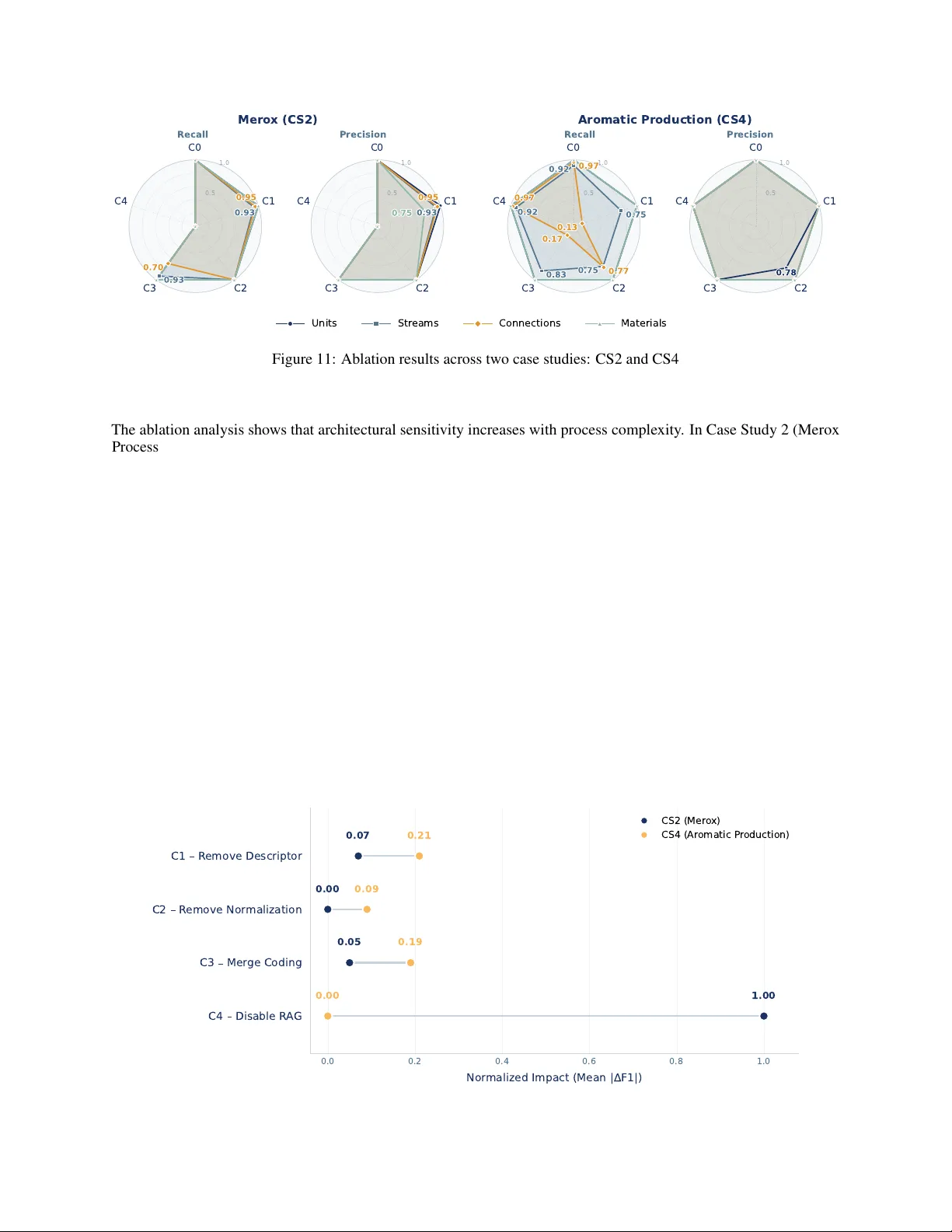
S K E T C H 2 S I M U L A T I O N : A U T O M A T I N G F L O W S H E E T G E N E R A T I O N V I A M U L T I A G E N T L A R G E L A N G U AG E M O D E L S Abdullah Bahamdan Sargent Centre for Process Systems Engineering Imperial College London London, SW7 2AZ, United Kingdom a.bahamdan22@imperial.ac.uk Emma Pajak Sargent Centre for Process Systems Engineering Imperial College London London, SW7 2AZ, United Kingdom emma.pajak19@imperial.ac.uk John D . Hedengren Department of Chemical Engineering Brigham Y oung Uni v ersity Prov o, Utah 84602, United States john.hedengren@byu.edu Antonio del Rio Chanona Sargent Centre for Process Systems Engineering Imperial College London London, SW7 2AZ, United Kingdom a.del-rio-chanona@imperial.ac.uk March 27, 2026 A B S T R AC T Con verting process sketches into e xecutable simulation models remains a major bottleneck in process systems engineering, requiring substantial manual ef fort, simulator-specific e xpertise, and iterati ve refinement. Although recent advances in generativ e AI hav e progressed both the automated inter- pretation of engineering diagrams and LLM-assisted flo wsheet generation, these two lines remain largely disconnected: diagram-understanding methods typically stop at extracted graphs or semantic representations, while text-to-simulation w orkflo ws assume structured inputs rather than raw visual artifacts. Bridging this gap requires recov ering structured process meaning from heterogeneous diagrams and instantiating simulator objects that satisfy strict creation, connecti vity , and initial- ization rules. T o address this, we present an end-to-end multi-agent large language model system that conv erts process diagrams directly into e xecutable Aspen HYSYS flo wsheets. The system decomposes the task across three coordinated layers: diagram parsing and interpretation, simulation model synthesis, and multi-lev el validation. Each layer consists of specialized agents handling visual interpretation, construction of a graph-based intermediate representation, code generation for the HYSYS COM interface, ex ecution, and structural verification. This decomposition enables execution grounding and explicit error localization, reducing hallucination risk while keeping failure modes transparent. W e ev aluate the framework on four chemical engineering case studies of increasing complexity , from a simple desalting process to an industrial-scale aromatic production flowsheet with multiple recycle loops. The system produces executable HYSYS models in all cases, achieving complete structural fidelity (F1 = 1.00 across all metrics) on the two simpler cases and maintaining high performance on the more complex ones (connection consistency ≥ 0 . 93 , stream consistency ≥ 0 . 96 ). Ablation analysis confirms that each architectural component contributes meaningfully to robustness, with sensiti vity increasing alongside diagram complexity . These results establish a viable end-to-end sketch-to-simulation automation in process systems engineering, while indicating that remaining challenges lie primarily in handling dense recycle structures, implicit diagram semantics, and simulator-interf ace constraints. K eyw ords Chemical Process Simulation · Large Language Model (LLMs) · Multi Agent System · Aspen HYSYS A P R E P R I N T - M A R C H 2 7 , 2 0 2 6 1 Introduction 1.1 Problem Context Process simulation stands as the computational backbone of modern chemical engineering practice, providing a sound basis for process design, analysis, and operational decision-making. Looking ahead, its importance is lik ely to gro w further as emerging paradigms such as digital twins, real-time optimization, and more autonomous modes of operation depend increasingly on continuously updated, high-quality , reliable process models Peterson et al. 2025. Howe ver , developing a high-fidelity simulation model remains a major practical bottleneck. The process often requires time-intensiv e manual ef fort, simulator-specific expertise, and repeated refinement, with ev en minor structural or specification errors capable of prev enting valid ex ecution. These challenges are further amplified when the starting point is a high-le vel process diagram rather than a structured digital representation. Methods and tools that automate simulation model generation are therefore becoming increasingly important for enabling faster , more reliable engineering workflo ws and for supporting the broader shift to wards digitalization and automation in process systems engineering (PSE) Liang et al. 2026; T ian et al. 2026. 1.2 Research Gap Process diagrams encode valuable engineering information, including major unit operations, material streams, and the ov erall topology of a process system. As such, they serve as a standard high-le vel representation for communicating process structure and design intent. Ho wever , despite the value of this information, con verting diagrams into executable simulation models remains a largely manual task: substantial interpretation, inference, and iterati ve refinement are required to yield a valid simulation T o wler and Sinnott 2013. A fundamental challenge arises from the gap between the information provided by process diagrams and the requirements of process simulation software. Diagrams are intended to support human understanding of process structure, whereas simulation en vironments require explicit, machine-interpretable definitions of units, stream connections, specifications, and initialization conditions. As a result, important information may be missing, implicit, or ambiguous in the source diagram. Therefore, con verting such diagrams into executable models requires more than extraction; it requires engineering interpretation and a structured synthesis process that or ganizes, supplements, and translates diagram content into simulator-compatible form. This work is motiv ated by the need to bridge the gap between diagram understanding and automated model generation. Recent advances in computer vision, including optical character recognition and multimodal artificial intelligence, have improv ed the identification and e xtraction of symbols, labels, and visual relationships from technical diagrams Bray et al. 2026; Shteriyanov et al. 2025. In parallel, prior approaches to automated model generation have shown how structured inputs can be con verted into e xecutable models Liang et al. 2026; T ian et al. 2026. Ho wev er , these two lines of work remain only partially connected. The former generally ends at recognition and e xtraction, whereas the latter typically assumes explicit, structured process inputs rather than raw diagrams. As a result, end-to-end frameworks capable of transforming raw visual inputs into v alidated, executable process simulation models remain limited. 1.3 Objective, Scope, and Contrib utions T o address the challenges of manual model dev elopment, this work proposes a multi-agent system for transforming process diagrams into ex ecutable process simulation models. The proposed workflo w is designed to bridge the gap between high-le vel engineering diagrams and simulator -ready process models through coordinated stages of diagram interpretation, structured model generation, and validation. The scope of the study is restricted to steady-state chemical process simulation, with Aspen HYSYS used as the target en vironment for model construction and execution. W ithin this scope, the main contributions of this work are threefold. First, it presents an end-to-end multi-agent architecture for automated process model generation from visual diagrams in chemical engineering. Second, it introduces a structured intermediate representation for con verting diagram-le vel information into simulator-compatible model elements. Third, it integrates automated model generation with v alidation and execution in Aspen HYSYS, and demonstrates the resulting workflo w across four case studies of increasing complexity . The remainder of this paper is organized as follo ws: Section 2 revie ws the background and related work on automated model generation. Section 3 presents the proposed multi-agent methodology . Section 4 describes the case studies used for ev aluation. Section 5 presents the results and discusses workflo w performance, robustness, and limitations. Finally , Section 6 concludes the work and outlines directions for future work. 2 A P R E P R I N T - M A R C H 2 7 , 2 0 2 6 2 Background and Related W ork 2.1 Process Simulation En vironments Process simulation en vironments are software platforms used to construct, specify , and execute computational models of process systems. Originating from early computer -aided flo wsheeting tools, they ha ve e v olved into mature systems with integrated thermodynamic methods, unit-operation libraries, and graphical interf aces. In chemical engineering, they are widely used across process design, analysis, optimization, and operational support, making them a central part of modern engineering workflo ws T owler and Sinnott 2013. As computing capabilities adv ance, their role has expanded beyond steady-state design calculations to include dynamic simulation and broader digital engineering applications. In practice, process simulation platforms are often categorized by their underlying computational architecture. Commer- cial en vironments such as Aspen HYSYS, Aspen Plus, and A VEV A PR O/II typically follow a Sequential Modular (SM) approach, in which unit operations are solved individually in a specified sequence AspenT ech 2026; A VEV A 2026. This architecture aligns closely with the visual logic of engineering diagrams. By contrast, platforms such as gPR OMS employ an Equation-Oriented (EO) formulation, in which the full system of algebraic and dif ferential equations is solved simultaneously Siemens 2026. Although EO platforms of fer greater flexibility for high-fidelity modeling and complex optimization, SM en vironments remain the industrial standard for general process design and analysis because of their robustness and intuiti ve flowsheet-based construction Dimian et al. 2014. W ithin this class of sequential-modular platforms, different en vironments have de veloped distinct areas of industrial emphasis. Aspen HYSYS is widely used and often preferred, particularly in oil and g as and broader energy applications, whereas Aspen Plus is more general-purpose and commonly associated with chemical process applications, including specialty chemicals and pharmaceuticals Chukwu et al. 2025. A VEV A PR O/II occupies a similar steady-state simulation space and has long been used across refining and chemical applications. These distinctions are not absolute, but the y illustrate how commercial simulation platforms with similar underlying architectures often ev olve toward dif ferent sectoral strengths. A ke y dif ferentiating feature of these en vironments is their support for external inte gration and automation. Modern commercial platforms expose their internal object models through application programming interfaces or interoperability layers such as COM (Component Object Model) or Python-based wrappers. These interfaces allo w external software, including the agents considered in this research, to programmatically construct and modify flo wsheets without manual graphical intervention K umar et al. 2025; Santos Bartolome and V an Gerven 2022. In addition, international standards such as CAPE-OPEN hav e sought to formalize interoperability across simulation platforms, enabling thermodynamic methods and unit-operation models to be exchanged more consistently between en vironments CO-LaN 2026. W ithin this landscape, Aspen HYSYS is selected as the target simulation environment for the present study . This choice is moti vated by its extensi ve industrial use and strong exposure in practice, particularly within the broader energy and manuf acturing industry , where it is widely used and often preferred for steady-state hydrocarbon process modeling. Although integrating automated workflows with a commercial platform such as HYSYS presents practical implementation challenges, including the orchestration of its COM-based object model, its industrial relev ance ensures that the proposed frame work is e v aluated against a rigorous real-world benchmark. Consequently , HYSYS provides a meaningful testbed for assessing the feasibility of translating diagrammatic intent into executable, simulator -compatible flowsheets. 2.2 Prior W ork on Diagram Understanding (A utomated Interpr etation of Engineering Diagrams) Prior work on engineering diagram understanding has ev olved from low-le vel visual e xtraction tow ard increasingly structured and semantically informed forms of analysis. In chemical engineering, this progression has been driven by a transition from rule-based and classical vision techniques to deep-learning, graph-aw are, and multimodal approaches that enable richer reasoning ov er process diagrams. The first stage focuses on element e xtraction. Early approaches treated process diagrams as visual documents whose basic components, such as text labels, symbols, arrows, and line objects, had to be identified separately . T o achiev e this, they typically combined OCR, template matching, Hough-transform-based line extraction, and rule-based visual processing to identify the visible building blocks of the diagram Kang et al. 2019; Moon et al. 2021; Rahul et al. 2019. While these methods performed well on relatively clean and standardized dra wings, they were often sensiti ve to clutter , inconsistent notation, ov erlapping lines, and the variability common in legac y scans and industrial diagrams. More recent deep-learning-based approaches improv ed the robustness of this stage by learning symbol, text, and feature representations directly from data, often using conv olutional neural networks or transformer -based vision models. This has been especially useful for dense or heterogeneous diagrams. Examples include deep-learning-based symbol and 3 A P R E P R I N T - M A R C H 2 7 , 2 0 2 6 text recognition in high-density P&IDs Kim, Lee, et al. 2021, feature recognition from image-format P&IDs Y u et al. 2019, and broader deep neural-network-based recognition of image-format P&IDs Su et al. 2024. The second stage extends beyond isolated recognition to ward topology reconstruction. At this point, the objectiv e is no longer only to detect visible elements, but to recover ho w they are connected and what process structure they represent. This includes associating labels with symbols, tracing pipelines, identifying stream connectivity , and representing the result as a graph or other digital process structure. End-to-end digitization frameworks such as Kim, Kim, et al. 2022 and Digitize-PID Paliw al et al. 2021 illustrate this transition by combining object recognition with topology reconstruction. Similar ideas appear in chemical PFD digitization, where deep-learning-based detection is follo wed by connectivity reco very to obtain a structured process representation Theisen et al. 2023. More recent work also mo ves tow ard joint structural prediction and highlights the need to identify omissions and inconsistencies after the initial parsing stage Kim, Moon, et al. 2025, reflecting a broader recognition that reliable engineering diagram interpretation often requires explicit v alidation when the output is intended for downstream technical use. The third stage focuses on semantic interpretation. Rather than stopping at the extracted structure, this stage treats the diagram as a semantic object that can support querying, higher-le vel reasoning, and do wnstream engineering use. This is reflected in recent multimodal and graph-grounded systems that transform static diagrams into structured knowledge representations and enable question answering or language-based interaction ov er them Gupta et al. 2025. These methods mark a clear shift from perception and topology recovery toward semantic interpretation. Howe ver , ev en at this lev el, the output typically remains a graph, knowledge base, or semantic representation rather than a simulator-ready model specification. In particular, current systems may identify that a unit, stream, or connection exists without supplying the domain-specific parameters, initialization conditions, and simulator constraints required for ex ecutable model synthesis. T aken together , these stages rev eal a clear pattern in the literature: the field has progressed from e xtracting visible elements, to reconstructing process topology , and more recently to interpreting engineering meaning. This progression is highly relev ant to the present work. Diagram understanding is a necessary foundation for automated model generation, but it is not suf ficient on its own. A significant gap remains between diagram interpretation and executable simulation models. The scope of current frameworks generally stops at e xtracted structures, graphs, or semantic representations, whereas simulation-model synthesis requires parameter inference, initialization logic, and simulator-specific mapping. In this sense, the remaining challenge is not only diagram underst anding, but also bridging the symbol-to-parameter gap between recognized engineering elements and ex ecutable process-model definitions. 2.3 Prior W ork on A utomated Model Generation 2.3.1 Optimization and Reinfor cement Learning Appr oaches Early work in this area emer ged from classical process synthesis, where automated flo wsheet generation was formulated as an optimization problem over a predefined superstructure of candidate units and connections. W ithin this framew ork, mathematical programming was used to select a feasible or optimal substructure from that design space Grossmann 1985; Pistikopoulos and T ian 2024; W esterberg 1989. Similarly , more recent symbolic approaches replace explicit superstructures with machine-readable encodings. For example, eSFILES represents process structures through symbolic flowsheet strings and uses these encodings as the basis for intelligent synthesis Mann et al. 2024. Rather than solving a fixed optimization problem directly , a second line of w ork casts flo wsheet generation as a sequential decision problem. A reinforcement learning agent constructs the flowsheet step by step by adding units and connections within a predefined synthesis en vironment Göttl et al. 2022. This perspecti ve has since been extended to include downstream design and control decisions, allowing generation to be coupled more closely with process performance and operability Reynoso-Donzelli and Ricardez-Sando v al 2025. Although these methods enable more flexible exploration of the design space than classical optimization-based synthesis, they still rely on predefined actions, candidate units, and constraints. Moreo ver , reinforcement learning is primarily designed for learning decision policies through repeated interaction, rather than for one-of f design synthesis tasks. In both cases, the process must first be represented in machine-readable form, and the output is typically a flowsheet configuration rather than a fully ex ecutable simulation model. 2.3.2 Semi-A utomatic, LLM, and Multi-Agent Appr oaches A transition to ward semi-automatic modules can be seen in the w ork of Sierla et al. 2020, where a digitalized P&ID is transformed into a directed graph and then into a simulator-specific flowsheet skeleton. Ho wev er, the workflow remained semi-automatic, since experts still had to choose the appropriate simulator blocks for the generated structure and complete the initialization and parameter settings needed to finalize the model. 4 A P R E P R I N T - M A R C H 2 7 , 2 0 2 6 LLMs and agentic systems extend automation further by shifting the interface from structured engineering data toward natural-language instructions and higher-le vel task orchestration. In the work Liang et al. 2026, for example, an LLM agent is integrated with A VEV A Process Simulation to support natural-language interaction, guided flo wsheet construction, data extraction, and optimization support. Their results sho w that step-by-step interaction is more reliable for guided model building, whereas single-prompt generation is faster b ut still requires expert oversight because of ov ersimplification and calculation errors. A more automated approach is proposed by T ian et al. 2026, who formulated text-to-simulation as a multi-agent workflo w with specialized agents for task understanding, topology generation, parameter configuration, and ev aluation analysis. Their system reports improv ed con ver gence and reduced design time, but it still be gins from textual process specifications as opposed to visual engineering inputs. A further extension appears in Srini vas et al. 2025, which adopts a more inte grated, physics-aw are frame work for the scale-up of chemical manufacturing. Rather than acting only as a simulator assistant or text-to-simulation pipeline, it generates PFDs and P&IDs from textual or retrie ved process descriptions and validates them through a simulator- supported closed-loop workflo w using DWSIM. This makes it one of the closest examples of closed-loop, agentic engineering generation, though it still starts from te xt or retrie ved kno wledge rather than from ra w visual engineering diagrams. A related extension of this trend appears in CeProAgents, which proposes a broader multi-agent frame work that spans knowledge retriev al, concept-lev el diagram reasoning, and simulator-based parameter optimization across the process dev elopment lifecycle. Conceptually , it is more integrated than simulator-assistant or text-to-simulation workflo ws, since it attempts to connect natural-language objectiv es, process-diagram abstractions, and Aspen-based optimization within one architecture. Ho we ver , the released implementation appears closer to a collection of partially connected modules than to a fully seamless end-to-end pipeline, with stronger support for parsing and optimization than for complete abstract-to-simulator model generation. As a result, it is best understood as an ambitious step toward integrated agentic process dev elopment rather than a complete solution for con verting raw engineering diagrams directly into ex ecutable simulation models Y ang, Li, Ma, et al. 2026. Collectiv ely , this literature shows that automated model generation in chemical engineering is already well dev eloped once the process has been e xpressed in a machine-readable form. Classical synthesis methods, symbolic representations, sequential generation frameworks, digital-twin pipelines, and agentic workflows all demonstrate different ways of automating flowsheet or model construction. The main limitation, howe ver , is that most of these approaches begin only after the representation problem has already been resolved. The y automate the transition from formal process description to flowsheet or simulator model, b ut not the earlier transition from ambiguous visual engineering input to a structured, simulator-ready representation. This is the distinction addressed in the present work, which connects visual interpretation with structured synthesis and validation within a single w orkflo w . 2.4 Multi-Agent Systems for Complex Engineering W orkflows A multi-agent system (MAS) is a system composed of multiple autonomous agents that perceive their en vironment, make local decisions, and act in pursuit of individual or collecti ve goals. An agent, in this context, is a computational entity capable of sensing relev ant inputs, reasoning ov er them, and performing actions directed tow ard a defined objectiv e. The broader contemporary literature often discusses such goal-directed autonomous behavior under the term Agentic AI, particularly when agents operate with planning, tool use, and limited human supervision Rupprecht et al. 2026. The defining feature of MAS is that problem solving is distrib uted rather than centralized: specialized agents interact through coordination, cooperation, or negotiation, and their collecti ve behavior can achie ve outcomes beyond those of isolated components. This makes MAS well-suited to complex, multi-step engineering problems that require distrib uted reasoning, modular task allocation, and coordination across various computational tools. In practice, MAS can take different forms depending on how kno wledge, decision-making, and coordination are organized. Information may be distributed across agents or shared through a common state, with agents updating their local or global view of the problem as ne w information becomes a v ailable. Agents can be instances of rule-based logic, optimization routines, reinforcement-learning policies, or large language models, depending on the role they are intended to perform. Coordination may be imposed through a centralized orchestrator or arise from direct interaction among agents. As a result, MAS can support both deterministic workflo ws, where e xecution order is predefined, and more adapti ve settings, where routing, sequencing, and task assignment e volve in response to intermediate results or changing system conditions. A key adv antage of multi-agent systems lies in their ability to support specialization and coordination at the same time. Here, architecture refers to the organizational structure through which agents are arranged, responsibilities are allocated, and interactions are coordinated. Such architectures may be sequential, hierarchical, or orchestrated through 5 A P R E P R I N T - M A R C H 2 7 , 2 0 2 6 a central controller , depending on how task dependencies and information flo w are managed. Different agents can be assigned different reasoning modes, representations, or external tools, while higher-lev el coordination mechanisms allow their outputs to be combined into a coherent workflow . This is especially useful when solving problems that require both local task e xpertise and global consistenc y . Rather than forcing all subtasks into a single representation or model, a multi-agent architecture allo ws perception, structure recov ery , parameter inference, and validation to be treated as related b ut distinct forms of reasoning. In chemical engineering, multi-agent systems ha ve e volved across sev eral generations. Early studies used agents as modular carriers of engineering kno wledge, decomposing complex tasks into specialized decision units for process design and fault diagnosis Eo et al. 2000; Han et al. 1995. Later work extended the scope to ward interoperability , enterprise coordination, distributed optimization, refinery applications, and fault diagnosis in transient operations to solve more comple x engineering tasks Julka et al. 2002; Seng and Srini vasan n.d.; Siirola et al. 2003; Stalker and Fraga 2004; Y ang, Braunschweig, et al. 2008. More recent research has introduced learning-enabled architectures, particularly reinforcement-learning-based multi- agent systems, in which agents adapt their behavior in response to intermediate results and support data-driven coordination in tasks such as process control and scheduling Hong et al. 2024; Y ue and Lakshminarayanan 2023. Building on this shift to ward adapti ve computation, the latest contributions ha ve e xpanded MAS further through agentic architectures that incorporate multimodal lar ge language models, retrie v al-augmented generation, graph-based retriev al, and tool use for tasks such as process improvement, industrial control, operational assistance, process optimization, and PFD/P&ID generation from te xt or multimodal inputs Du and Y ang 2025; Gow aikar et al. 2024; Lee et al. 2024; Sriniv as et al. 2025; Tian et al. 2026; Vyas and Mercangöz 2025; Zeng et al. 2025. This e volution is directly rele vant to the present work. Transforming a visual engineering diagram into an ex ecutable simulation model is not a single inference task, but a sequence of heterogeneous subtasks that includes visual interpreta- tion, structural reconstruction, simulator-specific mapping, specification completion, and execution-oriented v alidation. These subtasks differ not only in their inputs and outputs, b ut also in the type of reasoning they require. A multi-agent system, therefore, provides a natural architectural basis for this problem, because it allows these stages to be handled by specialized agents while still maintaining coordination across the ov erall workflo w . For this reason, the present work adopts a multi-agent system not simply as an implementation choice, b ut as a methodological response to the structure of the problem itself. The proposed workflow uses specialized agents to bridge visual engineering inputs and simulator-ready model generation through coordinated interpretation, synthesis, and validation. 2.5 Research Gap and P ositioning The literature has adv anced along two directions that remain insuf ficiently inte grated. On one side, engineering-diagram understanding has progressed from element extraction to topology reconstruction and semantic interpretation, but most methods still terminate at a graph or descripti ve representation rather than an e xecutable simulation model. On the other hand, recent multi-agent and agentic workflo ws have enabled increasingly capable text-to-simulation and simulator-assisted design, but the y usually begin from te xtual specifications, structured engineering data, or standardized intermediate forms. The unresolv ed gap lies in connecting these directions: transforming raw visual engineering diagrams directly into simulator-ready models. A further limitation is that many existing workflo ws are tied either to specific input formats or to non-industrial modeling en vironments. In practice, howe ver , engineering diagrams vary widely in notation, layout, completeness, and degree of standardization. A practically useful frame work should therefore not rely exclusi vely on highly standardized exchange formats, but should be able to operate across a broader range of engineering diagrams, including those encountered in less structured industrial settings. At the same time, industrial rele v ance depends on compatibility with widely used commercial simulators rather than only research-oriented platforms or custom prototypes. For this reason, the present work tar gets visual engineering inputs more broadly and uses Aspen HYSYS as the simulation en vironment. This work is positioned at the intersection of these gaps. It proposes an end-to-end multi-agent workflo w that begins from visual engineering diagrams rather than textual specifications and aims to generate executable simulation models rather than only topological or semantic representations. By combining diagram interpretation, structured synthesis, specification completion, and simulator-based v alidation within a single coordinated framework, the proposed system treats the simulator not as a passive output tar get but as an acti ve component of the generation and verification loop. In this way , the framework seeks to connect visual engineering inputs to simulator -ready model generation in a form that is both technically ex ecutable and industrially relev ant. 6 A P R E P R I N T - M A R C H 2 7 , 2 0 2 6 3 Methodology This work proposes a multi-agent system for transforming process diagrams into executable process simulation models. This section presents the methodology underlying the proposed framew ork, beginning with the ov erall system architecture, followed by detailed descriptions of the interpretation, synthesis, and validation layers. It then outlines the rationale for model selection and deployment, and concludes with the system implementation. 3.1 Multi-Agent System Architectur e The automated transformation of process diagrams into ready-to-use process simulation models is a complex reasoning task; it requires visual interpretation, information extraction, semantic parsing, and model synthesis, each with distinct logic and failure modes. Monolithic approaches built around a single LLM agent, therefore, tend to lose robustness as diagram complexity increases. More concretely , in multi-step reasoning tasks, as intermediate states accumulate within a single context windo w , attention allocation and context utilization become less reliable ov er dispersed e vidence, while composing multiple dependent subtasks within a single reasoning path makes errors harder to isolate, trace, and correct Brinkmann et al. 2024; Dziri et al. 2023; Liu et al. 2024. T o address these limitations, this study proposes a modular multi-agent system architecture, moti vated by prior literature that emphasizes the v alue of task decomposition, specialization, and error isolation in comple x reasoning workflo ws Guo et al. 2024. The architecture is org anized into three functional layers, each composed of specialized agents. As sho wn in Figure 1, the Diagram Parsing and Interpretation Layer transforms the visual input into a structured representation. The Simulation Model Synthesis Layer then translates this representation into an executable process model in the simulator en vironment. Throughout the workflo w , the Multi-level V alidation Layer applies targeted v alidation procedures to assess structural and semantic consistency at ke y stages. This layered design improves reliability , supports systematic error localization, and limits error propagation across stages. Si m ul a to r En vir on me nt A spen HY SY S V1 1 Di a g r a m P ars in g & Inte r p ret a t io n L aye r De scri pt o r A1 E xt r a ct o r A2 No r ma lizat io n A3 S i mu lat ion Mo d e l S yn the sis L ayer B a sis B1 Insta n t iatio n B2 Confi gur ation B3 E xe cutio n B4 In te r me d i a te Represe ntat io n De scri p tio n Val ida tio n A1 . 1 CO M API Wor kf low Fixe r B4 . 1 Or ch e s tr a to r P r o ce ss Di a g ra m Mu l t i - leve l V a lid a t io n L a ye r Figure 1: Multi agent system architecture W orkflow execution is go verned by a central orchestrator that manages state transitions between agents in a deterministic sequence. Each agent operates as a state transformer: it consumes a v alidated state from the preceding stage and returns a refined state for the next. This design enforces controlled and reproducible information flow while enabling tar geted trace-based issue localization at any point in the workflow Deshpande et al. 2025. Formally , let s k denote the workflo w state after stage k , and let A k denote the transformation implemented by the agent at that stage. The workflo w then ev olves as s k +1 = A k ( s k ) , where the orchestrator defines the ordered sequence of transformations { A 1 , A 2 , . . . , A n } . The final w orkflow state can therefore be written as s n = ( A n ◦ A n − 1 ◦ · · · ◦ A 1 )( s 0 ) . By assigning well-defined responsibilities to specialized agents, the architecture improv es traceability , enables targeted v alidation, and supports modular extension. It thereby enables automated process model synthesis directly from process diagrams, while also allowing additional capabilities to be incorporated without redesign, supporting future extensions tow ard broader automated process design workflo ws. 7 A P R E P R I N T - M A R C H 2 7 , 2 0 2 6 3.2 Diagram Parsing and Interpr etation Layer The Diagram Parsing and Interpretation Layer is the entry point of the workflo w . Process flo w diagrams encode rich design information through symbols, annotations, stream labels, and spatial arrangements. Howe ver , they often e xhibit visual clutter , inconsistent formatting, non-standard conv entions, and implicit connectivity assumptions, which mak e direct automated interpretation challenging. The role of this layer is to transform the unstructured visual input into a formalized Intermediate Representation (IR) that captures the process topology in a structured, simulator -compatible form. Formally , the IR is represented as a directed graph, G = ( V , E ) , where V denotes the set of unit operations and E ⊆ V × V denotes the directed material streams connecting source and destination units. In implementation, this graph is instantiated as a structured JSON schema comprising two principal collections: a set of units representing graph nodes, V , and a set of material streams representing directed edges, E . This representation preserves flo w directionality and provides a clear interface to do wnstream synthesis agents. The interpretation layer workflow comprises three agents: the Descriptor Agent (A1), the Extractor Agent (A2), and the Normalization Agent (A3), each discussed in the following subsections. 3.2.1 Descriptor Agent (A1) The Descriptor Agent (A1) uses a multimodal LLM to generate a detailed description of the process depicted in the input diagram. Prior to inference, the diagram is standardized to a fixed resolution to improve computational ef ficiency while preserving the spatial relationships required for process interpretation. The prompt enforces a left-to-right trav ersal heuristic and instructs the model to explicitly enumerate all visible process elements. T o improv e consistency , the prompt incorporates a self-ev aluation instruction that encourages the model to assess whether each described element is supported by observable visual e vidence in the diagram Madaan et al. 2023; W eng et al. 2023. The resulting description captures the ov erall process intent, identified unit operations, material streams, and their inlet-outlet relationships. 3.2.2 Extractor Agent (A2) Building on the output of Agent A1, the Extractor Agent (A2) emplo ys a multimodal LLM to construct the JSON-based Intermediate Representation. Both the original diagram and description produced by Agent A1 are parsed by this agent. The diagram remains the primary source of ground truth, while the generated description serves as a semantic prior that helps reduce ambiguity and improv e extraction reliability . T o improve rob ustness, extraction is performed in tw o inference passes. In the first pass, the agent identifies all visible unit operations and assigns unique identifiers. In the second pass, it extracts material streams, classifies them as feed, intermediate, or product streams, and restricts source-destination assignments to the unit set established in the first pass. This staged extraction procedure strengthens topological consistenc y and mitigates common LLM failure modes, including equipment hallucination, label misinterpretation, and inconsistent connecti vity assignments. It also localizes extraction errors, thereby limiting cross-stage error propagation. The output of Agent A2 is a structured Intermediate Representation that encodes the extracted process topology . 3.2.3 Normalization Agent (A3) Before the IR is passed to the synthesis layer, it is processed by the Normalization Agent (A3), a rule-based agent that enforces topological consistency and simulator -specific structural requirements. One responsibility of Agent A3 is to resolve implicit junctions commonly found in process diagrams. In many process diagrams, multiple streams con ver ge directly into unit operations that are designed to accept a single inlet stream, such as pumps or compressors. Although visually intuitiv e, such representations violate the nodal constraints imposed by the simulator . Agent A3 detects these multi-stream con vergences and inserts e xplicit mixing or splitting units into the IR, rerouting the associated streams to preserve process intent while satisfying simulator requirements. A second responsibility of Agent A3 is to align extracted process structures with simulator templates. Certain unit operations may appear in the diagram as multiple functional elements, b ut must be instantiated in the simulator as a single object. Distillation systems are an example of this: the column to wer, condenser , and reboiler may be extracted as separate elements, but they must be consolidated into a predefined unit operations template. Agent A3 therefore restructures the IR into a cohesi ve, template-compliant representation that can be instantiated as the corresponding simulator object. At the conclusion of the interpretation layer, the system produces a normalized, simulator-compatible Intermediate Representation of the process flowsheet. This IR then serves as the controlled input to the synthesis layer , where it is translated into an ex ecutable process simulation model. 8 A P R E P R I N T - M A R C H 2 7 , 2 0 2 6 3.3 Simulation Model Synthesis Layer The Simulation Model Synthesis Layer translates the formalized Intermediate Representation into an e xecutable process simulation model in Aspen HYSYS. T o achieve this, four specialized coding agents sequentially construct a Python automation script that interacts with the Aspen HYSYS Component Object Model (COM) interface. The agents operate on a shared Python template and modify only predefined execution blocks. This guided synthesis strategy enforces adherence to simulator-specific con ventions. The synthesis layer workflow comprises four agents: the Basis Agent (B1), the Instantiation Agent (B2), the Configura- tion Agent (B3), and the Execution Agent (B4), each discussed in the follo wing subsections. 3.3.1 Basis Agent (B1) The Basis Agent (B1) is a code-oriented LLM agent that establishes the simulation case basis by defining the case name, selecting the appropriate fluid property package, and constructing the component list required for the process. A ke y responsibility of the agent is translating the extracted feed components into v alid Aspen HYSYS component names. This translation is performed using a Retriev al-Augmented Generation (RA G) module that queries a curated knowledge base to align e xtracted material names with e xact entries in the HYSYS pure-component database, thereby ensuring that only simulator-compatible components are introduced into the simulation en vironment. 3.3.2 Instantiation Agent (B2) Once the simulation basis is established, the Instantiation Agent (B2), a code-oriented LLM agent, constructs the structural skeleton of the process flo wsheet. Operating directly on the IR graph, it translates the node set V and edge set E into ex ecutable code. Using the Aspen HYSYS COM automation interface, the agent maps unit operations and material streams to their corresponding simulator object classes. Dedicated instruction files guide object creation patterns for each supported unit type, ensuring compliance with the simulator object hierarchy and pre venting unsupported operations. By the end of this stage, the structural flowsheet has been instantiated within the simulation en vironment. 3.3.3 Configuration Agent (B3) Building on the instantiated flo wsheet, the Configuration Agent (B3), also a code-oriented LLM agent, establishes the topological connecti vity of the process model. Guided by the source-destination relationships encoded in the edge set E, it links material streams to the appropriate inlet and outlet ports of each unit operation through the COM automation interface. Unit-specific instruction files govern the connection logic for each object class, ensuring that streams are attached to valid ports in a simulator-consistent manner . As a result, the generated automation script defines a fully connected process model. 3.3.4 Execution Agent (B4) The synthesis layer concludes with the Execution Agent (B4), a hybrid agent that combines a rule-based ex ecution step with an LLM-based fixing step. The rule-based step ex ecutes the generated Python automation script without modifying the underlying model logic and records solver status, runtime diagnostics, and execution logs. If execution fails, a code-oriented LLM agent analyzes the execution trace and applies targeted corrections to the script before reattempting ex ecution. This stage serves as an e xecution-lev el validation step, confirming whether the generated model can run successfully within the simulator en vironment while supporting systematic issues tracing of the automated modeling workflo w . It therefore completes the transformation from a structured process representation into an executable process simulation model. 3.4 Multi-Level V alidation Layer T o improve the reliability , robustness, and traceability of the proposed frame work, v alidation is embedded at multiple le vels of the w orkflow . These v alidation procedures do not replace the core generati ve steps; rather , the y act as diagnostic checkpoints that identify inconsistencies, impro ve transparency , and support error localization. A summary of these procedures is provided in T able 1. 9 A P R E P R I N T - M A R C H 2 7 , 2 0 2 6 T able 1: Summary of v alidation mechanisms used in the proposed workflo w Mechanism Purpose Stage Description validation (A1.1) Assess alignment between the visual input and the generated description Post-descriptor (A1) Schema and prompt safeguards Enforce structured outputs, object constraints, and internal consistency Interpretation and synthesis agents Execution v alidation and fixing V alidate ex ecutability and apply tar- geted runtime corrections Execution (B4) W ithin the interpretation layer , an auxiliary Description V alidation Agent (A1.1) e valuates the output of the primary Descriptor Agent (A1). Operating on the original diagram, this secondary LLM acts as an independent e valuator that assesses whether the generated process description is aligned with the visual content of the diagram. Although it does not modify the description itself, it provides a confidence signal re garding its consistency with the source diagram. Additional safeguards are embedded directly within the prompts and output constraints used across the workflo w . In the interpretation layer , agents operate under strict JSON schemas to enforce properly structured intermediate outputs. In the synthesis layer , coding agents follow guided instruction files and constrained templates to maintain adherence to simulator requirements. Furthermore, internal consistency checks are embedded in selected prompts to encourage self-assessment before final output generation. Finally , end-to-end v alidation is performed during model e xecution, as discussed in Section 3.3.4. At this stage, ex ecution logs, solver diagnostics, and correction outcomes pro vide a final check on model ex ecutability and support error localization. T ogether , these procedures strengthen the reliability and traceability of the ov erall workflo w . 3.5 Model Selection and Deployment Model selection follo ws three design criteria: (i) modality alignment, ensuring that each model matches the form of its input data; (ii) computational ef ficiency , prioritizing models that enable reliable and scalable inference; and (iii) data gov ernance, requiring sensitiv e simulation logic to remain within a controlled local en vironment. Based on these criteria, the interpretation and synthesis layers are assigned to different model classes and deplo yment en vironments. 3.5.1 Interpr etation Models and Cloud Deployment The interpretation layer , comprising the Descriptor Agent (A1) and Extractor Agent (A2), uses Gemini 3 Flash, a proprietary multimodal LLM capable of joint reasoning ov er images and text Google DeepMind 2025. This capability is essential for interpreting process diagrams, which require scientific visual reasoning and strong optical character recognition (OCR) for the proper interpretation of symbols, stream labels, spatial connectivity , and textual annotations. This model selection is further supported by reported benchmark performance on demanding scientific reasoning tasks. Gemini 3 Flash achie ved 81 . 2% on the MMMU-Pro benchmark and 90 . 4% on GPQA Diamond, both of which ev aluate reasoning over comple x visual and scientific content Google DeepMind 2025; Rein et al. 2023; Y ue, Zheng, et al. 2025. These capabilities are directly rele vant to the interpretation of process diagrams. In comparison, the open-weight multimodal alternativ es considered in this study , such as Qwen 3.5 series, showed lower performance on these benchmark cate gories Qwen T eam 2026. The interpretation layer is deployed in a cloud en vironment since multimodal inference is computationally intensiv e. By contrast, the Normalization Agent (A3) operates locally and applies deterministic rule-based transformations to enforce structural consistency and simulator -specific requirements. Since this stage is algorithmic rather than generati ve, it does not require language model inference. 3.5.2 Synthesis Models and Local Deployment T o comply with industrial data-sensitivity requirements established by the project partner , the synthesis and execution tasks are deployed locally . This ensures that proprietary simulation structures and generated automation scripts remain within a controlled execution en vironment. W ith the exception of one confidential instruction file, the code used to reproduce the reported results is made av ailable. For the foundational code-synthesis tasks handled by the Basis Agent (B1) and Instantiation Agent (B2), the system uses Qwen2.5-Coder -7B, Hui et al. 2024. This model w as selected for its ef ficient local inference and reliable structured code generation, while also av oiding unnecessary computational cost. 10 A P R E P R I N T - M A R C H 2 7 , 2 0 2 6 For more demanding code reasoning tasks, the Configuration Agent (B3) and the fixing component associated with the Execution Agent (B4) use Qwen3-Coder -30B, Y ang, Li, Y ang, et al. 2025. These tasks require stronger multi-step reasoning to interpret connectivity relationships between unit operations, resolve simulator -specific dependencies, and analyze runtime errors during automated error tracing. This hybrid deployment strategy isolates computationally intensive multimodal interpretation tasks in the cloud en vironment while ensuring that proprietary simulation synthesis remains secure within a local execution en vironment. T able 2 summarizes the deployed models across the workflo w . T able 2: Model selection and deployment across w orkflow components Agent Model / logic core Agent type En vironment Descriptor (A1) Gemini 3 Flash Multimodal LLM Cloud V alidation (A1.1) Gemini 3 Flash Multimodal LLM Cloud Extractor (A2) Gemini 3 Flash Multimodal LLM Cloud Normalization (A3) Rule-based logic Rule-based agent Local Basis (B1) Qwen2.5-Coder-7B Code-oriented LLM Local Instantiation (B2) Qwen2.5-Coder-7B Code-oriented LLM Local Configuration (B3) Qwen3-Coder-30B Code-oriented LLM Local Execution and Fixing (B4) Rule-based logic + Qwen3-Coder-30B Hybrid Local 3.6 System Implementation The multi-agent workflo w is implemented in Python and orchestrated using LangGraph, which models the system architecture as a directed computational graph LangChain AI 2024. W ithin this structure, nodes represent indi vidual workflo w agents, including both LLM-based and rule-based agents, while edges define the ex ecution sequence and data dependencies. Intermediate data is encapsulated in structured state objects that propagate systematically between agents. These states contain the ev olving workflo w state, including extracted unit operations, material streams, normalized intermediate representations, and generated simulation code. Each agent reads the current state, applies its designated transformation, and returns an updated state to the subsequent node. At the agent lev el, LangChain provides abstractions for prompt construction, message handling, and structured output parsing. The implementation deliberately separates probabilistic reasoning from algorithmic ex ecution: LLMs are in voked only for tasks that require model-based reasoning, such as diagram interpretation and code synthesis, while rule-based agents operate directly on the workflo w state through deterministic Python transformations. Model inference is managed through Ollama, which provides a unified serving interface for both local and cloud-based models Ollama T eam 2023. Locally hosted code-synthesis models are served through Ollama on dedicated hardw are to satisfy industrial data-governance constraints, while the multimodal interpretation model is accessed through the Ollama cloud tier . Using a common serving interface simplifies inte gration within the orchestration layer and reduces infrastructure complexity . Aspen HYSYS was selected as the simulation en vironment because it is widely reg arded as the industry gold standard for steady-state process modeling and provides a programmable Component Object Model (COM) automation interf ace suitable for script-based flowsheet generation. Through this interface, the system can synthesize flowsheets, configure process connectivity , and ex ecute simulations without manual interaction with the graphical user interface. The system operates on the dedicated w orkstation en vironment summarized in T able 3. T ogether , these software and hardware components operationalize the multi-agent frame work described in Section 3.1, enabling automated diagram interpretation, model synthesis, validation, and simulation e xecution within a unified workflo w . 11 A P R E P R I N T - M A R C H 2 7 , 2 0 2 6 T able 3: Computational en vironment and software stack Category Component Specification Hardware en vironment CPU Intel Xeon Gold 6442Y (2.60 GHz) Memory 256 GB RAM GPU NVIDIA R TX A4000 (16 GB VRAM) Operating system W indows 11 (64-bit) Compute platform CUD A 12.8 Software stack Programming language Python 3.11.13 Agent framew ork LangChain Agent orchestration LangGraph 1.0.9 LLM serving framew ork Ollama 0.17.4 (local and cloud) Process simulator Aspen HYSYS V11 4 Case Studies The multi-agent system is ev aluated using four case studies representing common chemical engineering processes. The selected diagrams span increasing lev els of process and topological complexity , including variations in the number of unit operations, stream interconnectivity , labeling clarity , and layout density . The case studies, sho wn in T able 4 are presented in order of increasing complexity to enable a systematic ev aluation of the robustness, scalability , and structural reasoning capability of the workflo w . T able 4: Characteristics of the case study diagrams Case Process Unit operations Stream density Recycle loops Diagram characteristics 1 Desalting Low Sparse None Missing labels, implicit mixing 2 Merox Sweetening Moderate Moderate One Compact layout, ambiguous con- nectivity 3 Atmospheric Distillation Moderate Moderate One Non-standard symbols, partially labeled units 4 Aromatic Production High Dense Multiple Industrial-scale flo wsheet with complex interconnections T aken together , the four case studies provide a structured e v aluation across progressi vely increasing le vels of process and topological complexity . The selected diagrams range from a simple baseline process to industrial-scale flo wsheets with dense interconnections and multiple rec ycle loops. This progression enables a systematic assessment of the system’ s robustness, scalability , and limitations when applied to div erse process diagrams encountered in chemical engineering practice. 4.1 Case Study 1: Desalting Process The first case study considers a simplified crude oil desalting process obtained from a published process diagram (Figure 2) Pereira et al. 2015. In this process, crude oil and fresh water are pressurized by dedicated pumps, combined with a demulsifier agent, and routed to an electrostatic separator that produces desalted crude oil and effluent w ater . This case serves as a baseline scenario due to its low structural complexity and limited number of unit operations. Despite its simplicity , the diagram presents sev eral interpretation challenges, including unlabeled pumps, an implicitly represented mixing operation, and missing stream labels. These features test the workflo w’ s ability to correctly identify equipment and infer stream connectivity under minimal topological comple xity . 12 A P R E P R I N T - M A R C H 2 7 , 2 0 2 6 Figure 2: Desalting process (Pereira et al. 2015) 4.2 Case Study 2: Jet Fuel Sweetening (Merox) Pr ocess The second case study e xamines a jet fuel mercaptan oxidation treating process, commonly referred to as the Merox pro- cess. The corresponding process flo w diagram was obtained from a publicly av ailable source drawn using ConceptDra w , a diagramming platform (Figure 3) ConceptDraw 2026. The feed enters a caustic pre wash vessel, after which it is routed to the Merox reactor , where mercaptan oxidation occurs in the presence of an alkaline catalyst and compressed air . Reactor ef fluent flows to a caustic settler for phase separation, after which the hydrocarbon stream passes through water w ashing, salt bed drying, and clay bed polishing units before exiting as the final product. A portion of the aqueous caustic phase is recycled to maintain caustic strength. Relativ e to the baseline case, this flowsheet introduces moderate topological complexity . Although it follows stan- dardized con ventions, the flowsheet includes an internal rec ycle loop and ambiguous stream connecti vity . In addition, dense textual annotations and reaction equations increase visual clutter , requiring the workflo w to distinguish structural elements from e xplanatory content. This combination of features provides a useful stress test for the frame work’ s ability to interpret compact layouts and infer non-linear flow paths while maintaining structural consistenc y . Figure 3: Merox process (ConceptDraw 2026) 13 A P R E P R I N T - M A R C H 2 7 , 2 0 2 6 4.3 Case Study 3: Atmospheric Crude Oil Distillation Process The third case study considers a classical atmospheric crude oil distillation process sourced from an undergraduate chemical engineering thesis (Figure 4) Ogunleye 2021. The diagram represents a crude oil processing sequence consisting of crude preheating, desalting, fired heating, and atmospheric distillation. In this process, crude oil is withdrawn from a storage tank and pressurized by a feed pump before entering a preheating train. The preheated crude is mixed with wash water and routed to a desalter , where salts and entrained water are remov ed. The desalted crude then passes through a second preheating train and a fired heater before entering the atmospheric distillation column. Within the column, the feed is separated into multiple fractions, including ov erhead products, side draws such as naphtha, kerosene, diesel, and atmospheric g as oil, and a bottom residue stream. Compared with the previous cases, this e xample introduces additional interpretation challenges due to its non-standard formatting and limited equipment labeling. While process streams are identified, most equipment items are not explicitly labeled, creating ambiguity in unit recognition. The diagram also incorporates color-coded elements and uncon ventional symbols that deviate from standardized industrial flowsheet con ventions. As a result, the workflo w must rely more heavily on spatial relationships and conte xtual cues to infer unit roles and connectivity , thereby highlighting sensitivity to diagram quality rather than process complexity alone. Figure 4: Crude distillation process (Ogunleye 2021) 4.4 Case Study 4: Aromatic Production Pr ocess The final case study considers a fully integrated, industrial-scale aromatic production process, obtained from a chemical engineering design textbook (Figure 5) T urton 2009.The flowsheet encompasses a dense netw ork of reactor systems, separation columns, heat exchangers, rotating equipment, and multiple rec ycle streams. In this process, toluene is withdrawn from a storage drum and pressurized by feed pumps before being heated in a feed preheater and feed heater . The heated feed enters a reactor , where the primary reaction occurs in the presence of hydrogen. Reactor effluent is cooled and separated in a high-pressure separator , with part of the vapor phase compressed and recycled to the reactor . The liquid stream flows to a lo w-pressure separator, after which the h ydrocarbon stream is routed to a benzene distillation column. Ov erhead vapor from the column is condensed and collected in a reflux drum, where a portion is returned as reflux while the remainder is withdrawn as benzene product. A reboiler provides heat input to maintain column separation. Among the selected case studies, this flowsheet exhibits the highest le vel of process and topological complexity . The flo wsheet contains many unit operations, dense stream interconnections, and multiple rec ycle loops linking reaction and separation sections. The compact arrangement of equipment and numerous crossing streams increases visual layout density and makes connecti vity more difficult to interpret. Accordingly , this case tests the frame work’ s 14 A P R E P R I N T - M A R C H 2 7 , 2 0 2 6 ability to maintain global structural consistenc y across lar ge, interconnected flo wsheets, thereby providing a realistic representation of industrial process diagrams. Figure 5: Aromatic production process (Turton 2009) 5 Results and Discussion This section presents the results of applying the multi-agent system across four case studies. It first defines the e v aluation criteria, then discusses overall workflo w performance and ablation results. It next examines model beha vior , robustness, and v ariability at the multimodal reasoning level, and concludes with practical limitations and a summary of ke y findings. 5.1 Evaluation Criteria A combination of quantitati ve and qualitati ve criteria is used to systematically assess the performance of the multi-agent system. The quantitati ve metrics measure structural fidelity relativ e to reference diagrams, while the qualitative criteria assess model behavior , robustness, and failure characteristics observed across the four case studies. For the quantitati ve analysis, four metrics are defined to ev aluate the accuracy of a process simulation model: Unit Consistency (UC), Stream Consistency (SC), Connection Consistenc y (CC), and Material Consistency (MC), as summarized in T able 5. T able 5: Quantitati ve e valuation metrics Metric Evaluated element Purpose Unit Consistency (UC) Unit operations Evaluates the correctness of e xtracted unit operations Stream Consistency (SC) Material streams Evaluates the correctness of e xtracted material flows Connection Consistency (CC) Directed unit-to-unit connectivity Evaluates the correctness of process topology Material Consistency (MC) Feed and process material components Evaluates the correctness of e xtracted material and com- ponent identities Each consistency metric is computed using the F1-score formulation V an Rijsber gen 1979: F 1 = 2 P R P + R 15 A P R E P R I N T - M A R C H 2 7 , 2 0 2 6 The F1-score provides a harmonic mean of precision and recall, ensuring balanced penalization of both error types. For a giv en structural element set X (units, streams, connections, or materials), precision ( P ) represents the proportion of extracted elements that are correct, and recall ( R ) represents the proportion of reference elements that are successfully extracted, defined as: P = T P T P + F P , R = T P T P + F N where T rue Positi ves, T P , denote correctly extracted elements present in the reference diagram, F alse Positiv es, F P , denote extracted elements not present in the reference diagram (hallucinated elements), and F alse Negati ves, F N , denote reference elements that were not extracted (missing elements). This formulation ensures that omissions and hallucinations are penalized simultaneously , rather than rewarding structural completeness alone. The quantitative metrics alone do not fully capture system beha vior; therefore, qualitati ve analysis is also used to interpret the results. Section 5.2 ev aluates performance across the four case studies, focusing on structural accuracy and execution stability . Section 5.3 then examines the contribution of individual agents through controlled ablation analysis. Section 5.4 analyzes model beha vior , reproducibility , and multimodal benchmarking. Finally , Section 5.5 discusses practical limitations and deployment considerations. T ogether , these analyses provide a comprehensi ve assessment of the system. 5.2 Overall P erformance Across all four case studies, the multi-agent system successfully generated e xecutable process simulation models. As summarized in Figure 6. Units Streams Units Streams Connections Materials Case Complexity Extraction Performance (F1) Aromatic Production (C S4) Crude Distillation (C S3) Merox (C S2) Desalting (C S1) 1.00 0.96 0.98 1.00 1.00 1.00 0.93 1.00 1.00 1.00 1.00 1.00 1.00 1.00 1.00 1.00 4 Figure 6: Overall structural performance across the four case studies For Case Study 1 (Desalting Process), the system achiev ed full structural consistency , correctly identifying all feed materials, unit operations, streams, and connections. The resulting simulation model, shown in Figure 7, executed without errors and required no fixing-loop intervention. T o ensure simulator compatibility , the system introduced a mixer and an intermediate stream to formalize the mixing operation. This modification reflects simulator-dri ven structural normalization rather than hallucinated model content. Overall, this case demonstrates that the sys tem can recov er simple process topologies with complete accuracy and stable e xecution. T u e M a r 1 7 1 3 : 4 0 : 1 2 2 0 2 6 C a se : C r u d e O i l D e sa l i n a t i o n P r o ce ss. h sc F l o w sh e e t : C a se ( M a i n ) Crude Oil Pump Fresh W ater Pump Mixer Mixing Valve Electrostatic Separator Crude oil Fresh water Demulsifier agent Fresh water discharge Oil-water mixture Mixer to Valve Desalted crude oil Effluent W ater Crude oil discharge Figure 7: Generated HYSYS flowsheet corresponding to the desalting process 16 A P R E P R I N T - M A R C H 2 7 , 2 0 2 6 For Case Study 2 (Merox Process), structural consistency remained complete and the generated model executed successfully , as shown in Figure 8. The system correctly inferred connectivity between the caustic pre wash vessel and the Merox reactor , although this connection was omitted from the diagram. This result demonstrates robust topological reconstruction under moderate visual ambiguity , showing that the system can recov er process-consistent connections while preserving ex ecutability . T u e M a r 1 7 1 3 : 4 1 : 4 7 2 0 2 6 C a se : Je t F u e l M e r ca p t a n O xi d a t i o n P r o ce ss. h sc F l o w sh e e t : C a se ( M a i n ) Caustic prewash Merox reactor E Caustic settler Caustic circulation pump Wat er wash Salt bed Clay bed Jet fuel feed Fresh caustic batch Compressed air Prewashed fuel Reactor effluent Caustic phase Recycled caustic Fuel phase Wash ed fuel Dried fuel Spent caustic drain Wat er wash drain Salt bed drain Sweetened jet fuel Figure 8: Generated HYSYS flowsheet corresponding to the Merox process In Case Study 3 (Atmospheric Crude Oil Distillation Process), the system remained accurate in identifying the core structural elements of the flo wsheet. A slight reduction in connection consistency w as observed, as sho wn in Figure 9, primarily in relation to side-draw connections from the distillation column. This discrepancy originated at the automation interface rather than the interpretation stage. As discussed in Section 3.2.3, distillation columns in Aspen HYSYS are instantiated using predefined internal templates that encapsulate stage-lev el connecti vity , thereby limiting direct programmatic control over certain side-stream attachments through the Python COM automation interface. Consequently , the deviation reflects simulator -interface limitations rather than errors in diagram interpretation, since the relev ant side-draw streams were correctly represented in the graph-based Intermediate Representation. T u e M a r 1 7 1 3 : 4 8 : 5 6 2 0 2 6 C a se : C r u d e O i l D e sa l i n a t i o n P r o ce ss_ cs3 . h sc F l o w sh e e t : C a se ( M a i n ) Crude_Oil_Storage_Tank Feed_Pump Pre-heat_Train_1 Mixer Desalter Pre-heat_Train_2 Fired_Heater Atmospheric_Distillation_Column Crude_Feed Water_Feed S1 F-102 F-103 F-104 F-105 F-106 Salt_Water Flue_Gas Off-gas Waste_W ater Naphtha Kero Diesel AGO Residue F-101 Figure 9: Generated HYSYS flowsheet corresponding to the crude distillation process Case Study 4 (Aromatic Production Process) represents the most complex industrial-scale flowsheet ev aluated. Structural fidelity remained high (F1 ≈ 0 . 98 ), with minor deviations in stream and connection consistency , as shown in Figure 10. The generated model omitted the fuel gas header and one recycle stream between the feed pump and storage drum. Additionally , the quench stream source was misassigned from the recycle gas compressor to the feed heater . These discrepancies occurred within densely interconnected rec ycle sections, where multiple ov erlapping streams increase tracing difficulty . Despite these minor structural de viations, the overall model ex ecuted successfully in HYSYS. This result indicates that the system remains highly robust e ven in industrial-scale flowsheets, despite minor connection errors in branched stream networks. 17 A P R E P R I N T - M A R C H 2 7 , 2 0 2 6 T u e M a r 1 7 1 3 : 5 0 : 4 6 2 0 2 6 C a se : T o l u e n e H y d r o d e a l k y l a t i o n P r o ce ss. h sc F l o w sh e e t : C a se ( M a i n ) Toluene Storage Drum Toluene Feed Pumps Mixer to E-101 Feed Preheater Feed Heater Reactor E Reactor Effluent Cooler High-Pres. Phase Sep. Recycle Gas Compressor Low-Pres. Phase Sep. Tower Feed Heater Benzene Column Product Cooler Fresh Toluene Hydrogen Feed Recycle Toluene Toluene Feed Reactor Feed Preheated Feed Hot Feed Quench Stream Reactor Effluent Two-Phase Mixture Separator Overhead Gas Recycle Gas Separator Liquid Liquid Bottoms Column Feed Product Flow Mixer outlet to E-101 Fuel Gas Purge Overhead Gas Benzene Product Figure 10: Generated HYSYS flowsheet corresponding to the aromatic production process Overall, the results demonstrate strong structural fidelity across case studies of increasing complexity . Minor reductions in performance are primarily associated with interconnection density and simulator-specific limitations rather than errors in diagram interpretation. Execution stability remained consistent across all cases, underscoring the robustness of the multi-agent system across div erse process flow diagrams. 5.3 Ablation Analysis Four ablation studies were designed to assess the contrib ution of individual components within the multi-agent workflo w . As summarized in T able 6, each configuration selectiv ely disables or modifies a specific agent within either the diagram interpretation layer or the model synthesis layer . This setup enables a systematic assessment of ho w disabling a gi ven component affects structural consistenc y and simulation ex ecutability relative to the full-w orkflow baseline (C0). The analysis is conducted across Case Study 2 (Merox Process) and Case Study 4 (Aromatic Production Process) to e v aluate architectural robustness under moderate and high process comple xity . T able 6: Ablation configurations Configuration T arget Purpose C0 – Full W orkflow All Baseline configuration C1 – Remov e Descriptor A1 Evaluate the contrib ution of visual-text grounding C2 – Remov e Normalization A3 Evaluate the contrib ution of structural refinement C3 – Merge Coding Agents B1–B3 Evaluate the contrib ution of modular code decomposition C4 – Disable RA G B1 Evaluate the contrib ution of retriev al-based material mapping Figure 11 reports precision and recall for units, streams, connections, and material components across the ablation configurations (C1–C4) relati ve to the full-workflo w baseline (C0). These plots pro vide a metric-le vel vie w of structural degradation under controlled architectural perturbations. Reductions in recall indicate missing structural elements, whereas declines in precision reflect the introduction of incorrect or hallucinated elements. 18 A P R E P R I N T - M A R C H 2 7 , 2 0 2 6 0.5 1.0 C0 C1 C2 C3 C4 0.5 1.0 C0 C1 C2 C3 C4 0.5 1.0 C0 C1 C2 C3 C4 0.5 1.0 C0 C1 C2 C3 C4 Merox (C S2) Aromatic Production (C S4) Recall Precision Recall Precision Units Str eams Connections Materials Figure 11: Ablation results across two case studies: CS2 and CS4 The ablation analysis sho ws that architectural sensiti vity increases with process complexity . In Case Study 2 (Merox Process), unit and stream consistency remain largely preserved across configurations; ho we ver , connection consistency decreases substantially under coding consolidation (C3), indicating that modular code separation is essential for maintaining correct topology . Disabling RA G (C4) results in complete ex ecution failure because Aspen HYSYS constructs models sequentially; unresolv ed material components therefore pre vent successful case initialization and terminate simulation. In Case Study 4 (Aromatic Production Process), which is characterized by dense interconnections and rec ycle structures, architectural modifications produce more pronounced degradation. Remov al of the descriptor agent (C1) or consolidation of coding agents (C3) significantly reduces connection consistency , while omission of the normalization stage (C2) introduces hallucinated structural elements that lo wer precision. In contrast to Case Study 2, disabling RA G (C4) does not affect performance, as the Aromatic Production Process relies on pure components rather than mixtures. T aken together , these results indicate that structural fidelity in highly interconnected flo wsheets depends critically on coordinated multi-agent processing rather than the performance of isolated agents. The normalized impact dumbbell chart, shown in Figure 12, provides a consolidated view of the relati ve importance of individual w orkflo w components. The impact score is defined as the mean absolute change in F1-score ( ∆ F1) relativ e to the baseline, where ∆ F1 captures the de viation introduced by each ablation across units, streams, connections, and materials. Higher values, therefore, correspond to greater w orkflow disruption. The dumbbell chart further indicates that each component contrib utes meaningfully to o verall rob ustness, with different components becoming critical as diagram complexity increases. 0.0 0.2 0.4 0.6 0.8 1.0 Nor malized Impact (Mean | F1|) C1 R emove Descriptor C2 R emove Nor malization C3 Mer ge Coding C4 Disable R A G 0.07 0.21 0.00 0.09 0.05 0.19 0.00 1.00 CS2 (Mer o x) CS4 (Ar omatic P r oduction) Figure 12: Normalized impact across ablation configurations 19 A P R E P R I N T - M A R C H 2 7 , 2 0 2 6 5.4 Model Behavior , Robustness, and V ariability T o complement the previous analysis, this section examines model stability and sensitivity at the multimodal reasoning lev el. It focuses on reproducibility under deterministic decoding and on the influence of model architecture on connectivity reconstruction in comple x process diagrams. 5.4.1 Reproducibility Analysis Reproducibility was e v aluated by ex ecuting the Descriptor Agent fiv e times per case study under strictly deterministic decoding conditions, as sho wn in T able 7. T emperature was set to 0.0, top- k to 1, top- p to 1.0, and the random seed was fixed at 42 to eliminate stochastic sampling. Under these settings, any observed variation reflects interpreti ve differences arising from visual reasoning rather than probabilistic decoding. T able 7: Deterministic inference parameters Parameter V alue Purpose T emperature 0.0 Remov es probabilistic sampling T op-k 1 Selects only the highest-probability tok en T op-p 1.0 Disables variability from nucleus sampling Seed 42 Ensures consistent behavior across ex ecutions The consistency across runs was quantified using cosine similarity between sentence embeddings of the generated descriptions, reporting both mean pairwise similarity and worst-case de viation Reimers and Gure vych 2019. Case Studies 1, 3, and 4 exhibit near-perfect reproducibility (mean similarity ≥ 0 . 9889 ). Case Study 2 (Merox Process) shows the only noticeable v ariability (mean = 0 . 9594 ; worst case = 0 . 8986 ), which is attrib uted to diagram-specific ambiguity rather than model instability . The Merox flowsheet contains dense te xtual annotations and reaction equations, increasing visual clutter, while the connection between the caustic prewash vessel and the reactor is only implicitly represented. Across trials, this ambiguous connectivity was occasionally interpreted differently , producing minor structural variation. 5.4.2 Model Benchmark or Multimodal Architectur e Benchmark A benchmarking study was conducted to e v aluate the influence of multimodal model selection on reconstruction quality . The analysis focused on the interpretation layer , specifically the Descriptor Agent (A1) and Extractor Agent (A2), since their underlying multimodal models were pre viously identified as the primary determinants of reconstruction accuracy . The deployed model, Gemini 3 Flash, was benchmarked against two state-of-the-art open-weight alternati ves: Qwen 3-VL:235B and Qwen 3.5: 397B Bai et al. 2025; Qwen T eam 2026. The ev aluation was performed on Case Study 2 (Merox Process), which was selected as a controlled stress test because of its intermediate complexity , implicit connectivity , and dense annotation, making it well-suited for assessing multimodal spatial reasoning. 0.7 0.8 0.9 1.0 Units Streams Connections Materials Gemini Flash 3 Qwen 3.5 Qwen 3- VL Figure 13: Comparison of F1 scores across different LLMs 20 A P R E P R I N T - M A R C H 2 7 , 2 0 2 6 Figure 13 summarizes the performance of the e valuated models according to the metrics defined in Section 5.1. Gemini 3 Flash achie ved complete consistenc y across all e valuated elements, accurately reconstructing units, streams, connections, and material components. Qwen 3.5 recov ered the ov erall topology with high fidelity but exhibited connection-lev el inconsistencies, including misrouting of the compressed air stream and incorrect placement of liquid drain outlets. While these errors did not collapse the topology , they reduced connecti vity accurac y . In contrast, Qwen 3-VL showed substantially lo wer robustness, hallucinating an additional equipment unit (the coalescer section) and misplacing multiple stream connections. The resulting topology required extensiv e manual intervention before simulation, indicating insufficient cross-modal structural alignment. The observed performance reflects underlying architectural dif ferences. Qwen 3-VL employs a classical late-fusion vision-language paradigm in which visual features are encoded independently before being interpreted by the language model. This separation increases susceptibility to spatial ambiguity and weakens connectivity inference. Qwen 3.5 adopts a nativ e early-fusion multimodal architecture with improved attention mechanisms, enabling tighter cross-modal alignment and reducing connectivity errors. Gemini 3 Flash further extends multimodal integration through an iterativ e visual inspection mechanism, referred to as agentic vision, which enables localized refinement of ambiguous or densely annotated regions before structural commitment Google DeepMind 2026. Overall, these findings indicate that model architecture and fusion strategy are critical to object recognition and spatial reasoning in the reconstruction of complex flowsheets. 5.5 Practical Implications and Limitations Despite strong overall performance, a few limitations were observed. These limitations can be grouped into three categories: diagram interpretation challenges, simulator constraints, and infrastructure deployment considerations. From a visual standpoint, performance is sensitive to diagram quality and formatting. Implicit or partially drawn elements, such as units or connections, increase ambiguity and complicate process interpretation. Dense textual ov erlays, such as embedded reaction equations, increase OCR sensiti vity and visual clutter, occasionally affecting stream tracing. In complex flowsheets, recycle loops and non-linear routing amplify small parsing deviations into measurable topological inconsistencies. Internal elements embedded within vessels, such as catalyst beds, may also be misinterpreted as standalone units in weaker multimodal models. Diagrams with omitted connections, implied operations, or under-labeled stream routing may therefore require engineering inference beyond the directly visible structure. Simulator constraints also affect e xecutability . Aspen HYSYS constructs models sequentially , so incorrect material component definitions can prevent case initialization and terminate execution. In addition, complex unit operations such as distillation columns rely on predefined template structures that limit dynamic stream assignment through the automation interface. As a result, the correct interpretation of the diagram does not always guarantee a directly ex ecutable simulator model because of restrictions in the simulator interface and object hierarchy . Moreov er , the system depends on carefully designed prompts, structured schemas, and simulator -specific instruction files. Consequently , transferring the multi-agent system to a different simulator or process domain may require additional adaptation. Likewise, substituting the currently deplo yed models may necessitate prompt refinements, as the e xisting prompts are tailored to the reasoning style, response behavior , and complexity-handling capabilities of those models. From an infrastructure perspecti ve, multimodal reasoning o ver high-resolution process flo w diagrams is computationally intensiv e. Cloud-based inference introduces dependence on external compute allocation and dynamic batching, which may affect latenc y and reproducibility (runtime consistency). LLM inference requires increased processing time when resolving dense diagrams or performing iterativ e visual reasoning. Practical deployment, therefore, requires balancing structural accuracy with computational cost, response time, and hardware a vailability . This creates an operational trade-off in which higher reconstruction accuracy may require larger multimodal models, longer inference times, and greater hardware demand, particularly for visually dense or industrial-scale diagrams. 6 Conclusion The proposed framew ork demonstrates the feasibility of transforming raw process diagrams into executable Aspen HYSYS simulation models through a coordinated multi-agent w orkflow . This claim is supported by the fact that the system successfully generated e xecutable models in all four case studies, spanning flo wsheets of increasing process and topological complexity . Structural fidelity remained perfect in the first tw o cases, with recov ered units, streams, connections, and material components all equal to 1.00, while the more challenging Crude Distillation (CS3) and Aromatics Production (CS4) cases still maintained high performance, with only limited reductions in connection and stream consistency (CS3: CC = 0.93; CS4: SC = 0.96, CC = 0.98). In addition, the generated models remained 21 A P R E P R I N T - M A R C H 2 7 , 2 0 2 6 ex ecutable e ven in the most complex industrial-scale case, despite dense recycle structures and minor connection deviations. By integrating multimodal extraction, structural normalization, code generation, and ex ecution-based validation, the system therefore extends prior diagram-understanding approaches be yond descripti ve reconstruction tow ard ex ecutable model synthesis. Nev ertheless, the study also makes clear that the central challenge is not merely visual recognition. The more dif ficult problem lies in preserving engineering intent while translating imperfect, ambiguous, and sometimes implicit visual structures into forms that satisfy the rigid logical and object-le vel constraints of a commercial simulator . Errors arise not only from missed symbols or incorrect stream tracing, but also from mismatches between diagram con ventions and simulator requirements. As a result, successful automation depends on the joint handling of perception, engineering reasoning, and simulator compatibility rather than on any one of these in isolation. Future work should therefore focus on improving generality , robustness, and engineering realism. One important direction is to extend the framew ork beyond relati vely clean process flo w diagrams toward noisier and more het- erogeneous industrial artifacts, including scanned diagrams, legac y documents, and mix ed diagram-text engineering records. A second direction is to develop simulator -agnostic intermediate abstractions that can support deployment across multiple process simulation environments rather than a single commercial platform. A third direction is to strengthen self-correction through confidence-aware extraction, retrie val of engineering design rules, and more explicit simulator-in-the-loop repair c ycles. Finally , broader validation on larger and more di verse industrial case studies will be needed to assess scalability , transferability , and practical deployment readiness. T aken together , these directions point tow ard a broader class of engineering systems in which visual interpretation, domain reasoning, and executable model synthesis are integrated into a unified automation pipeline. 7 Data A vailability & Repr oducibility The project codebase is publicly available in the open-source GitHub repository https://github.com/ OptiMaL- PSE- Lab/Sketch2Simulation . The repository also includes the case study diagrams required for the analysis. W ith access to the necessary language models and a HYSYS licence, the results presented in this work can therefore be reproduced. Certain agent instruction files, including instantiation_instructions_*.txt and configuration_instructions_*.txt , are not included in the repository . These files contain proprietary HYSYS- domain prompt engineering materials and must therefore be obtained separately . 8 Acknowledgments Financial support provided by B ASF SE, EPSRC IConIC Prosperity Partnership (EP/X025292/1), and EPSRC CDT (EP/S023232/1) is acknowledged. References AspenT ech (2026). Aspen HYSYS . U R L : https : / / www . aspentech . com / en / products / engineering / aspen - hysys . A VEV A (2026). A VEV A PR O/II Simulation – The T rusted Steady-State Process Simulator . U R L : https://www.aveva. com/en/products/pro- ii- simulation/ . Bai, Shuai, Y uxuan Cai, Ruizhe Chen, K eqin Chen, Xionghui Chen, Zesen Cheng, Lianghao Deng, W ei Ding, Chang Gao, Chunjiang Ge, W enbin Ge, Zhifang Guo, Qidong Huang, Jie Huang, Fei Huang, Binyuan Hui, Shutong Jiang, Zhaohai Li, Mingsheng Li, Mei Li, Kaixin Li, Zicheng Lin, Jun yang Lin, Xuejing Liu, Jiawei Liu, Chenglong Liu, Y ang Liu, Dayiheng Liu, Shixuan Liu, Dunjie Lu, Ruilin Luo, Chenxu Lv, Rui Men, Lingchen Meng, Xuancheng Ren, Xingzhang Ren, Sibo Song, Y uchong Sun, Jun T ang, Jianhong T u, Jianqiang W an, Peng W ang, Pengfei W ang, Qiuyue W ang, Y uxuan W ang, T ianbao Xie, Y iheng Xu, Haiyang Xu, Jin Xu, Zhibo Y ang, Mingkun Y ang, Jianxin Y ang, An Y ang, Bowen Y u, Fei Zhang, Hang Zhang, Xi Zhang, Bo Zheng, Humen Zhong, Jingren Zhou, Fan Zhou, Jing Zhou, Y uanzhi Zhu, and Ke Zhu (Nov . 27, 2025). Qwen3-VL T echnical Report . D O I : 10 . 48550 / arXiv . 2511 . 21631 . arXiv: 2511 . 21631[cs] . U R L : http : / / arxiv . org / abs / 2511 . 21631 (visited on 03/15/2026). Bray , Nick, Michael Hempel, Matthew Boeding, and Hamid Sharif (Feb . 2026). “Decoding T echnical Diagrams: A Surve y of AI Methods for Image Content Extraction and Understanding”. In: Information 17.2, p. 165. I S S N : 2078-2489. D O I : 10.3390/info17020165 . U R L : https://www.mdpi.com/2078- 2489/17/2/165 (visited on 03/15/2026). 22 A P R E P R I N T - M A R C H 2 7 , 2 0 2 6 Brinkmann, Jannik, Abhay Sheshadri, V ictor Levoso, Paul Swoboda, and Christian Bartelt (June 30, 2024). A Mec ha- nistic Analysis of a T ransformer T rained on a Symbolic Multi-Step Reasoning T ask . D O I : 10.48550/arXiv.2402. 11917 . arXiv: 2402.11917[c s] . U R L : http://arxiv.org/abs/2402.11917 (visited on 03/14/2026). Chukwu, Arinze JohnPaul, Ob umneme Okwonna, and Peter Muw arure (Mar . 30, 2025). “Optimising the gas-oil ratio for enhanced production”. In: Global J ournal of Engineering and T echnology Advances 22.3, pp. 131–142. I S S N : 25825003. D O I : 10 . 30574 / gjeta . 2025 . 22 . 3 . 0052 . U R L : https : / / gjeta . com / node / 815 (visited on 03/15/2026). ConceptDraw (2026). Jet fuel mercaptan oxidation tr eating - PFD | Pr ocess Diagr ams | Chemical and Pr ocess Engineering | Mer ox Pr ocess Flow Diagram . U R L : https : / / www . conceptdraw . com / examples / merox - process- flow- diagram (visited on 03/14/2026). Deshpande, Darshan, V arun Gangal, Hersh Mehta, Jitin Krishnan, Anand Kannappan, and Rebecca Qian (June 23, 2025). TRAIL: T race Reasoning and Agentic Issue Localization . D O I : 10 . 48550 / arXiv . 2505 . 08638 . arXiv: 2505.08638[cs] . U R L : http://arxiv.org/abs/2505.08638 (visited on 03/14/2026). Dimian, Alexandre C., Costin Sorin Bildea, and Anton A. Kiss (2014). Inte grated Design and Simulation of Chemical Pr ocesses . V ol. 35. Computer Aided Chemical Engineering. Elsevier. U R L : https://www.sciencedirect.com/ bookseries/computer- aided- chemical- engineering/vol/35/suppl/C . Du, W enli and Shaoyi Y ang (Oct. 2025). “The potential and challenges of lar ge language model agent systems in chemical process simulation: from automated modeling to intelligent design”. In: F r ontiers of Chemical Science and Engineering 19.10, p. 99. I S S N : 2095-0179, 2095-0187. D O I : 10 . 1007 / s11705 - 025 - 2587 - 5 . U R L : https://link.springer.com/10.1007/s11705- 025- 2587- 5 (visited on 03/15/2026). Dziri, Nouha, Ximing Lu, Melanie Sclar, Xiang Lorraine Li, Liwei Jiang, Bill Y uchen Lin, Peter W est, Chandra Bhagav atula, Ronan Le Bras, Jena D. Hwang, Soumya San yal, Sean W elleck, Xiang Ren, Allyson Ettinger, Zaid Harchaoui, and Y ejin Choi (Oct. 31, 2023). F aith and F ate: Limits of T ransformers on Compositionality . D O I : 10 . 48550 / arXiv . 2305 . 18654 . arXiv: 2305 . 18654[cs] . U R L : http : / / arxiv . org / abs / 2305 . 18654 (visited on 03/14/2026). Eo, Soo Y oung, T ae Suk Chang, Dongil Shin, and En Sup Y oon (2000). “Cooperative Problem Solving in Di- agnostic Agents for Chemical Processes”. In: Computers & Chemical Engineering 24.2, pp. 729–734. D O I : 10 . 1016 / S0098 - 1354(00 ) 00329 - X . U R L : https : / / www . sciencedirect . com / science / article / pii / S009813540000329X . Google DeepMind (Dec. 2025). Gemini 3 Flash . V ersion 3.0. U R L : https://deepmind.google/models/gemini/ flash/ . — (Jan. 27, 2026). Intr oducing Agentic V ision in Gemini 3 Flash . U R L : https://blog.google/innovation- and- ai/technology/developers- tools/agentic- vision- gemini- 3- flash/ . Göttl, Quirin, Dominik G. Grimm, and Jakob Bur ger (2022). “Automated Synthesis of Steady-State Continuous Processes Using Reinforcement Learning”. In: F r ontiers of Chemical Science and Engineering 16, pp. 288–302. D O I : 10 . 1007 / s11705 - 021 - 2055 - 9 . U R L : https : / / link . springer . com / article / 10 . 1007 / s11705 - 021- 2055- 9 . Gow aikar , Shreeyash, Sriniv asan Iyengar, Sameer Segal, and Shivkumar Kalyanaraman (Dec. 17, 2024). An Agentic Appr oach to Automatic Cr eation of P&ID Diagr ams fr om Natural Languag e Descriptions . D O I : 10.48550/arXiv. 2412.12898 . arXiv: 2412.1289 8[cs] . U R L : http://arxiv.org/abs/2412.12898 (visited on 03/15/2026). Grossmann, Ignacio E. (1985). “Mixed-Integer Programming Approach for the Synthesis of Integrated Process Flowsheets”. In: Computers & Chemical Engineering . D O I : 10. 1016 / 0098 - 1354(85 ) 80023 - 5 . U R L : https: //www.sciencedirect.com/science/article/pii/0098135485800235 . Guo, T aicheng, Xiuying Chen, Y aqi W ang, Ruidi Chang, Shichao Pei, Nitesh V . Cha wla, Olaf W iest, and Xiangliang Zhang (Apr . 19, 2024). Large Langua ge Model based Multi-Agents: A Surve y of Pr ogr ess and Challenges . D O I : 10 . 48550 / arXiv . 2402 . 01680 . arXiv: 2402 . 01680[cs] . U R L : http : / / arxiv . org / abs / 2402 . 01680 (visited on 03/14/2026). Gupta, Mohit, Chialing W ei, Thomas Czerniawski, and Ricardo Eiris (2025). “PIDQA—Question Answering on Piping and Instrumentation Diagrams”. In: Machine Learning and Knowledge Extraction 7.2, p. 39. D O I : 10 . 3390 / make7020039 . U R L : https://www.mdpi.com/2504- 4990/7/2/39 . Han, Chonghun, James M. Douglas, and George Stephanopoulos (1995). “Agent-Based Approach to a Design Support System for the Synthesis of Continuous Chemical Processes”. In: Computers & Chemical Engineering 19 (Sup- plement 1), S63–S69. D O I : 10 . 1016 / 0098 - 1354(95 ) 87016 - 4 . U R L : https : / / www . sciencedirect . com / science/article/pii/0098135495870164 . Hong, Sunghoon, Deunsol Y oon, Whiyoung Jung, Jinsang Lee, Hyundam Y oo, Jiwon Ham, Suh yun Jung, Chanwoo Moon, Y eontae Jung, Kanghoon Lee, W oohyung Lim, Somin Jeon, Myounggu Lee, Sohui Hong, Jaesang Lee, Hangyoul Jang, Changhyun Kwak, Jeonghyeon P ark, Changhoon Kang, and Jungki Kim (2024). “Naphtha Crack- ing Center Scheduling Optimization Using Multi-Agent Reinforcement Learning”. In: Proceedings of the 23rd 23 A P R E P R I N T - M A R C H 2 7 , 2 0 2 6 International Confer ence on Autonomous Agents and Multiag ent Systems (AAMAS 2024) , pp. 2806–2808. U R L : https://www.ifaamas.org/Proceedings/aamas2024/pdfs/p2806.pdf . Hui, Bin yuan, Jian Y ang, Ze yu Cui, Jiaxi Y ang, Dayiheng Liu, Lei Zhang, T ianyu Liu, Jiajun Zhang, Bo wen Y u, K eming Lu, Kai Dang, Y ang Fan, Y ichang Zhang, An Y ang, Rui Men, Fei Huang, Bo Zheng, Y ibo Miao, Shanghaoran Quan, Y unlong Feng, Xingzhang Ren, Xuancheng Ren, Jingren Zhou, and Junyang Lin (Nov . 12, 2024). Qwen2.5-Coder T echnical Report . D O I : 10. 48550 / arXiv. 2409 . 12186 . arXiv: 2409. 12186[cs] . U R L : http: / / arxiv. org / abs/2409.12186 (visited on 03/14/2026). Julka, Nirupam, Iftekhar A. Karimi, and Rajagopalan Sriniv asan (2002). “Agent-Based Supply Chain Manage- ment—2: A Refinery Application”. In: Computers & Chemical Engineering 26.12, pp. 1771–1781. D O I : 10 . 1016 / S0098 - 1354(02 ) 00151 - 5 . U R L : https : / / www . sciencedirect . com /science / article / abs / pii / S0098135402001515 . Kang, Sung-O, Eul-Bum Lee, and Hum-Kyung Baek (2019). “A Digitization and Conv ersion T ool for Imaged Drawings to Intelligent Piping and Instrumentation Diagrams (P&ID)”. In: Energies 12.13, p. 2593. D O I : 10 . 3390/en12132593 . U R L : https://www.mdpi.com/1996- 1073/12/13/2593 . Kim, Ji-Beob, Y oochan Moon, Seung-T ae Han, and Duhwan Mun (2025). “Automated Inspection of P&ID Object Recognition Using Deep Learning”. In: Scientific Reports 15.1, p. 39031. D O I : 10.1038/s41598- 025- 25506- 2 . U R L : https://www.nature.com/articles/s41598- 025- 25506- 2 . Kim, Byung Chul, Hyungki Kim, Y oochan Moon, Gwang Lee, and Duhwan Mun (2022). “End-to-End Digitiza- tion of Image Format Piping and Instrumentation Diagrams at an Industrially Applicable Lev el”. In: J ournal of Computational Design and Engineering 9.4, pp. 1298–1326. D O I : 10 . 1093 / jcde / qwac056 . U R L : https : //academic.oup.com/jcde/article/9/4/1298/6611631 . Kim, Hyungki, W onyong Lee, Mijoo Kim, Y oochan Moon, T aekyong Lee, Mincheol Cho, and Duhwan Mun (2021). “Deep-Learning-Based Recognition of Symbols and T exts at an Industrially Applicable Lev el from Images of High-Density Piping and Instrumentation Diagrams”. In: Expert Systems with Applications 183, p. 115337. D O I : 10 . 1016 / j . eswa . 2021 . 115337 . U R L : https : / / www . sciencedirect . com / science / article / abs / pii / S0957417421007661 . Kumar , Anikesh, Chi Hung V o, Md Shahabuddin Ahmmad, Sushant Suhas Garud, and Ifthekar Karimi (2025). Inte grating Coding Platforms with Pr ocess Simulators for Custom Applications . D O I : 10.2139/ssrn.5189453 . U R L : https://www.ssrn.com/abstract=5189453 (visited on 03/15/2026). CO-LaN (2026). CAPE-OPEN Laboratories Network . U R L : https://www.colan.org/ . LangChain AI (2024). LangGraph: Building stateful, multi-actor applications with LLMs . V ersion 0.2.0. U R L : https: //github.com/langchain- ai/langgraph . Lee, Donghyeon, Joon Lee, and Donggil Shin (2024). “GPT Prompt Engineering for a Lar ge Language Model-Based Process Improvement Generation System”. In: K or ean J ournal of Chemical Engineering 41.12, pp. 3263–3286. D O I : 10 . 1007 / s11814 - 024 - 00276 - 1 . U R L : https : / / link . springer . com / article / 10 . 1007 / s11814 - 024- 00276- 1 . Liang, Jingkang, Niklas Groll, and Gürkan Sin (Jan. 30, 2026). Lar ge Langua ge Model Agent for User-friendly Chemical Pr ocess Simulations . D O I : 10 . 48550 / arXiv . 2601 . 11650 . arXiv: 2601 . 11650[physics] . U R L : http://arxiv.org/abs/2601.11650 (visited on 03/15/2026). Liu, Nelson F ., Ke vin Lin, John He witt, Ashwin Paranjape, Michele Bevilacqua, Fabio Petroni, and Percy Liang (2024). “Lost in the Middle: Ho w Language Models Use Long Contexts”. In: T ransactions of the Association for Computational Linguistics 12, pp. 157–173. D O I : 10 . 1162 / tacl _ a _ 00638 . U R L : https : / / aclanthology . org/2024.tacl- 1.9/ (visited on 03/14/2026). Madaan, Aman, Niket T andon, Prakhar Gupta, Skyler Hallinan, Luyu Gao, Sarah W iegref fe, Uri Alon, Nouha Dziri, Shrimai Prabhumoye, Y iming Y ang, Shashank Gupta, Bodhisattwa Prasad Majumder, Katherine Hermann, Sean W elleck, Amir Y azdanbakhsh, and Peter Clark (May 25, 2023). Self-Refine: Iterative Refinement with Self-F eedback . D O I : 10. 48550/ arXiv .2303 .17651 . arXiv: 2303. 17651[cs] . U R L : http: // arxiv .org /abs / 2303. 17651 (visited on 03/14/2026). Mann, V ipul, Mauricio Sales-Cruz, Rafiqul Gani, and V enkat V enkatasubramanian (2024). “eSFILES: Intelligent Process Flo wsheet Synthesis Using Process Kno wledge, Symbolic AI, and Machine Learning”. In: Computers & Chemical Engineering 181, p. 108505. U R L : https : / / www . sciencedirect . com / science / article / abs / pii/S0098135423003757 . Moon, Y oochan, Jinwon Lee, Duhwan Mun, and S. Lim (2021). “Deep Learning-Based Method to Recognize Line Objects and Flow Arro ws from Image-Format Piping and Instrumentation Diagrams for Digitization”. In: Applied Sciences 11.21, p. 10054. D O I : 10.3390/app112110054 . U R L : https://www.mdpi.com/2076- 3417/11/21/ 10054 . Ogunleye, T obiloba (Oct. 21, 2021). MODELING, SIMULA TION AND CONTR OL OF A MODULAR REFINERY . D O I : 10.31224/3846 . 24 A P R E P R I N T - M A R C H 2 7 , 2 0 2 6 Ollama T eam (2023). Ollama: Get up and running with lar ge languag e models locally . V ersion 0.18.0. U R L : https: //github.com/ollama/ollama . Paliwal, Shubham, Arushi Jain, Monika Sharma, and Lo vek esh V ig (2021). “Digitize-PID: Automatic Digitization of Piping and Instrumentation Diagrams”. In: v ol. 12705, pp. 168–180. D O I : 10.1007 /978 - 3- 030 - 75015- 2 _17 . arXiv: 2109.03794[cs] . U R L : http://arxiv.org/abs/2109.03794 (visited on 03/15/2026). Pereira, Juan, Ingrid V elásquez, Ronald Blanco, Meraldo Sanchez, César Pernalete, and Carlos Canelon (Sept. 30, 2015). “Crude Oil Desalting Process”. In: pp. 67–84. I S B N : 978-953-51-2176-3. D O I : 10.5772/61274 . Peterson, Luisa, Ion V ictor Gosea, Peter Benner, and Kai Sundmacher (2025). “Digital twins in process engineering: An ov erview on computational and numerical methods”. In: Computers & Chemical Engineering 193, p. 108917. D O I : 10 . 1016 / j . compchemeng . 2024 . 108917 . U R L : https : / / www . sciencedirect . com / science / article / pii/S0098135424003351 . Pistikopoulos, Efstratios N. and Y uhe T ian (July 24, 2024). “Advanced Modeling and Optimization Strate gies for Process Synthesis”. In: Annual Revie w of Chemical and Biomolecular Engineering 15.1, pp. 81–103. I S S N : 1947-5438, 1947-5446. D O I : 10 . 1146 / annurev - chembioeng - 100522 - 112139 . U R L : https : / / www . annualreviews . org/content/journals/10.1146/annurev- chembioeng- 100522- 112139 (visited on 03/15/2026). Qwen T eam (Feb . 2026). Qwen3.5: T owards Native Multimodal Ag ents . U R L : https://qwen.ai/blog?id=qwen3.5 . Rahul, Rohit, Shubham Paliw al, Monika Sharma, and Lo vekesh V ig (2019). “Automatic Information Extraction from Piping and Instrumentation Diagrams”. In: Pr oceedings of the 8th International Confer ence on P attern Recognition Applications and Methods (ICPRAM) , pp. 163–172. D O I : 10 . 5220 / 0007376401630172 . U R L : https://www.scitepress.org/Papers/2019/73764/73764.pdf . Reimers, Nils and Iryna Gure vych (Aug. 27, 2019). Sentence-BERT: Sentence Embeddings using Siamese BERT- Networks . D O I : 10 . 48550 / arXiv . 1908 . 10084 . arXiv: 1908 . 10084[cs] . U R L : http : / / arxiv . org / abs / 1908.10084 (visited on 03/14/2026). Rein, David, Betty Li Hou, Asa Cooper Stickland, Jackson Petty, Richard Y uanzhe Pang, Julien Dirani, Julian Michael, and Samuel R. Bowman (Nov . 20, 2023). GPQA: A Graduate-Level Google-Pr oof Q&A Benchmark . D O I : 10. 48550/ arXiv. 2311 .12022 . arXiv: 2311. 12022[cs] . U R L : http: // arxiv. org /abs /2311 .12022 (visited on 03/14/2026). Reynoso-Donzelli, Simone and Luis A. Ricardez-Sandov al (2025). “A Reinforcement Learning Approach for Simul- taneous Generation, Design and Control of Reaction-Separation Process Flowsheets”. In: IF AC-P apersOnLine 59.6, pp. 247–252. I S S N : 24058963. D O I : 10 . 1016 / j . ifacol . 2025 . 07 . 153 . U R L : https : / / linkinghub . elsevier.com/retrieve/pii/S2405896325005130 (visited on 03/15/2026). Rupprecht, Sophia, Qinghe Gao, T anuj Karia, and Artur M Schweidtmann (Mar . 2026). “Multi-agent systems for chemical engineering: a re view and perspecti ve”. In: Curr ent Opinion in Chemical Engineering 51, p. 101209. I S S N : 22113398. D O I : 10. 1016/ j. coche .2025 .101209 . U R L : https: // linkinghub. elsevier .com /retrieve / pii/S2211339825001212 (visited on 03/15/2026). Santos Bartolome, Pedro and T om V an Gerven (2022). “A Comparative Study on Aspen Hysys Interconnection Methodologies for Chemical Engineering Purposes”. In: Computers & Chemical Engineering 162, p. 107785. D O I : 10 . 1016 / j . compchemeng . 2022 . 107785 . U R L : https : / / www . sciencedirect . com / science / article / abs/pii/S0098135422001260 . Seng, Ng Y ew and Rajagopalan Srini vasan (n.d.). “Multi-agent Frame work for F ault Detection & Diagnosis in T ransient Operations”. In: (). Shteriyanov , V asil I., R. Dzhusupov a, Jan Bosch, and Helena Holmström-Olsson (Dec. 2025). “Enhancing OCR-based Engineering Diagram Analysis by Integrating Div erse External Legends with VLMs”. In: Journal of Softwar e: Evolution and Pr ocess 37.12, e70072. D O I : 10.1002/smr.70072 . U R L : https://onlinelibrary.wiley.com/ doi/10.1002/smr.70072 . Siemens (2026). gPR OMS Process . U R L : https://www.siemens.com/en- us/products/gproms/ . Sierla, Sami et al. (2020). “T ow ards Semi-Automatic Generation of a Steady State Digital T win from Process and Instrumentation Diagram”. In: Applied Sciences 10.19, p. 6959. D O I : 10 . 3390 / app10196959 . U R L : https : / / research . aalto . fi / files / 52421947 / ELEC _ Sierla _ etal _ Towards _ Semi _ Automatic _ AppSci _ 2020_10_finalpublishedversion.pdf . Siirola, John D., Steinar Hauan, and Arthur W . W esterberg (2003). “T oward Agent-Based Process Systems Engineering: Proposed Framew ork and Application to Non-Con vex Optimization”. In: Computers & Chemical Engineering 27.12, pp. 1801–1811. D O I : 10.1016/S0098 - 1354(03 )00152- 2 . U R L : https://www .sciencedirect.com/ science/article/abs/pii/S0098135403001522 . Sriniv as, Sakhinana Sagar, Shiv am Gupta, and V enkataramana Runkana (Aug. 18, 2025). AutoChemSc hematic AI: Agentic Physics-A ware A utomation for Chemical Manufacturing Scale-Up . D O I : 10.48550/arXiv.2505.24584 . arXiv: 2505.24584[cs] . U R L : http://arxiv.org/abs/2505.24584 (visited on 03/15/2026). 25 A P R E P R I N T - M A R C H 2 7 , 2 0 2 6 Stalker , Iain D. and Eric S. Fraga (2004). “COGents Support for Automation in Process Design”. In: Computer Aided Chemical Engineering . V ol. 18, pp. 1141–1146. D O I : 10.1016/S1570- 7946(04)80256- 6 . U R L : https: //www.sciencedirect.com/science/article/pii/S1570794604802566 . Su, Guanqun, Shuai Zhao, T ao Li, Shengyong Liu, Y aqi Li, Guanglong Zhao, and Zhongtao Li (2024). “Image Format Pipeline and Instrument Diagram Recognition Method Based on Deep Learning”. In: Biomimetic Intelligence and Robotics 4.1, p. 100142. D O I : 10. 1016 / j. birob . 2023. 100142 . U R L : https: / / www. sciencedirect . com/ science/article/pii/S2667379723000566 . Theisen, Maximilian F ., Kenji Nishizaki Flores, Lukas Schulze Balhorn, and Artur M. Schweidtmann (2023). “Digiti- zation of Chemical Process Flow Diagrams Using Deep Con volutional Neural Networks”. In: Digital Chemical Engineering 6, p. 100072. D O I : 10. 1016/ j. dche. 2022. 100072 . U R L : https: // www. sciencedirect. com/ science/article/pii/S2772508122000631 . T ian, Xufei, W enli Du, Shaoyi Y ang, Han Hu, Hui Xin, Shifeng Qu, and K e Y e (Jan. 11, 2026). F r om T ext to Simulation: A Multi-Agent LLM W orkflow for Automated Chemical Pr ocess Design . D O I : 10 . 48550 / arXiv . 2601 . 06776 . arXiv: 2601.06776[cs] . U R L : http://arxiv.org/abs/2601.06776 (visited on 03/15/2026). T owler , Ga vin and Ray Sinnott (2013). Chemical Engineering Design: Principles, Practice , and Economics of Plant and Pr ocess Design . 2nd ed. Oxford: Butterworth-Heinemann. I S B N : 978-0-08-096659-5. U R L : https://ptgmedia. pearsoncmg.com/images/9780132618120/samplepages/0132618125.pdf . T urton, Richard, ed. (2009). Analysis, synthesis, and design of chemical pr ocesses . 3rd ed. Prentice Hall PTR interna- tional series in the physical and chemical engineering sciences. Upper Saddle Ri ver , N.J: Prentice Hall. 1068 pp. I S B N : 978-0-13-512966-1. V an Rijsbergen, C. J. (1979). Information Retrie val . Butterworths. Vyas, Jav al and Mehmet Mercangöz (2025). “Autonomous Industrial Control using an Agentic Frame work with Large Language Models”. In: IF AC-P apersOnLine 59.6, pp. 349–354. I S S N : 24058963. D O I : 10 . 1016 / j . ifacol . 2025.07.170 . U R L : https://linkinghub.elsevier.com/retrieve/pii/S2405896325005300 (visited on 03/15/2026). W eng, Y ixuan, Minjun Zhu, Fei Xia, Bin Li, Shizhu He, Shengping Liu, Bin Sun, Kang Liu, and Jun Zhao (Oct. 19, 2023). Lar ge Languag e Models ar e Better Reasoners with Self-V erification . D O I : 10.48550/arXiv.2212.09561 . arXiv: 2212.09561[cs] . U R L : http://arxiv.org/abs/2212.09561 (visited on 03/14/2026). W esterberg, Arthur W . (1989). “Synthesis in Engineering Design”. In: Computers & Chemical Engineering 13.4, pp. 365–376. D O I : 10.1016 /0098 - 1354(89)85016 - 1 . U R L : https:/ /www . sciencedirect. com/science / article/pii/0098135489850161 . Y ang, Aidong, Benoit Braunschweig, Eric S. Fraga, Zahia Guessoum, W olfgang Marquardt, Otmane Nadjemi, David Paen, Daniel Piñol, Philippe Roux, Sergio Sama, Marta Serra, and Iain Stalker (2008). “A Multi-Agent System to Facilitate Component-Based Process Modeling and Design”. In: Computers & Chemical Engineering 32.10, pp. 2290–2305. D O I : 10 . 1016 / j . compchemeng . 2007 . 11 . 005 . U R L : https : / / www . sciencedirect . com / science/article/abs/pii/S009813540700289X . Y ang, An, Anfeng Li, Baosong Y ang, Beichen Zhang, Bin yuan Hui, Bo Zheng, Bo wen Y u, Chang Gao, Chengen Huang, Chenxu Lv, Chujie Zheng, Dayiheng Liu, Fan Zhou, Fei Huang, Feng Hu, Hao Ge, Haoran W ei, Huan Lin, Jialong T ang, Jian Y ang, Jianhong T u, Jianwei Zhang, Jianxin Y ang, Jiaxi Y ang, Jing Zhou, Jingren Zhou, Junyang Lin, Kai Dang, Keqin Bao, K exin Y ang, Le Y u, Lianghao Deng, Mei Li, Mingfeng Xue, Mingze Li, Pei Zhang, Peng W ang, Qin Zhu, Rui Men, Ruize Gao, Shixuan Liu, Shuang Luo, Tianhao Li, T ianyi T ang, W enbiao Y in, Xingzhang Ren, Xinyu W ang, Xinyu Zhang, Xuancheng Ren, Y ang Fan, Y ang Su, Y ichang Zhang, Y inger Zhang, Y u W an, Y uqiong Liu, Zekun W ang, Ze yu Cui, Zhenru Zhang, Zhipeng Zhou, and Zihan Qiu (May 14, 2025). Qwen3 T echnical Report . D O I : 10. 48550/ arXiv. 2505 .09388 . arXiv: 2505. 09388[cs] . U R L : http: // arxiv. org /abs /2505 .09388 (visited on 03/14/2026). Y ang, Y uhang, Ruikang Li, Jifei Ma, Kai Zhang, Qi Liu, Jianyu Han, Y onggan Bu, Jibin Zhou, Defu Lian, Xin Li, and Enhong Chen (Mar . 2, 2026). CePr oAgents: A Hier ar chical Ag ents System for A utomated Chemical Pr ocess Development . D O I : 10.48550/arXiv.2603.01654 . arXi v: 2603.01654[cs] . U R L : 2603.01654 (visited on 03/15/2026). Y u, Eun-Seop, Jae-Min Cha, T aekyong Lee, Jinil Kim, and Duhwan Mun (2019). “Features Recognition from Piping and Instrumentation Diagrams in Image Format Using a Deep Learning Network”. In: Ener gies 12.23, p. 4425. D O I : 10.3390/en12234425 . U R L : https://www.mdpi.com/1996- 1073/12/23/4425 . Y ue, Xiang, T ianyu Zheng, Y uansheng Ni, Y ubo W ang, Kai Zhang, Shengbang T ong, Y uxuan Sun, Botao Y u, Ge Zhang, Huan Sun, Y u Su, W enhu Chen, and Graham Neubig (May 22, 2025). MMMU-Pr o: A Mor e Robust Multi-discipline Multimodal Understanding Benchmark . D O I : 10 . 48550 / arXiv . 2409 . 02813 . arXi v: 2409 . 02813[cs] . U R L : http://arxiv.org/abs/2409.02813 (visited on 03/14/2026). Y ue, Y ifei and Samav edham Lakshminarayanan (2023). “Multi-Agent Reinforcement Learning for Process Control: Exploring the Intersection Between Fields of Reinforcement Learning, Control Theory , and Game Theory”. In: 26 A P R E P R I N T - M A R C H 2 7 , 2 0 2 6 The Canadian J ournal of Chemical Engineering . D O I : 10.1002/cjce.24878 . U R L : https://onlinelibrary. wiley.com/doi/10.1002/cjce.24878 . Zeng, T ong, Sriv athsan Badrinarayanan, Janghoon Ock, Cheng-Kai Lai, and Amir Barati Farimani (Oct. 16, 2025). LLM-guided Chemical Pr ocess Optimization with a Multi-Agent Appr oach . D O I : 10.48550/arXiv.2506.20921 . arXiv: 2506.20921[cs] . U R L : http://arxiv.org/abs/2506.20921 (visited on 03/15/2026). 27
Original Paper
Loading high-quality paper...
Comments & Academic Discussion
Loading comments...
Leave a Comment