RIS-Assisted D-MIMO for Energy-Efficient 6G Indoor Networks
We propose an alternating optimization framework for maximizing energy efficiency (EE) in reconfigurable intelligent surface (RIS) assisted distributed MIMO (D-MIMO) systems under both coherent and non-coherent reception modes. The framework jointly …
Authors: Akshay Vayal Parambath, Jose Flordelis, Venkatesh Tentu
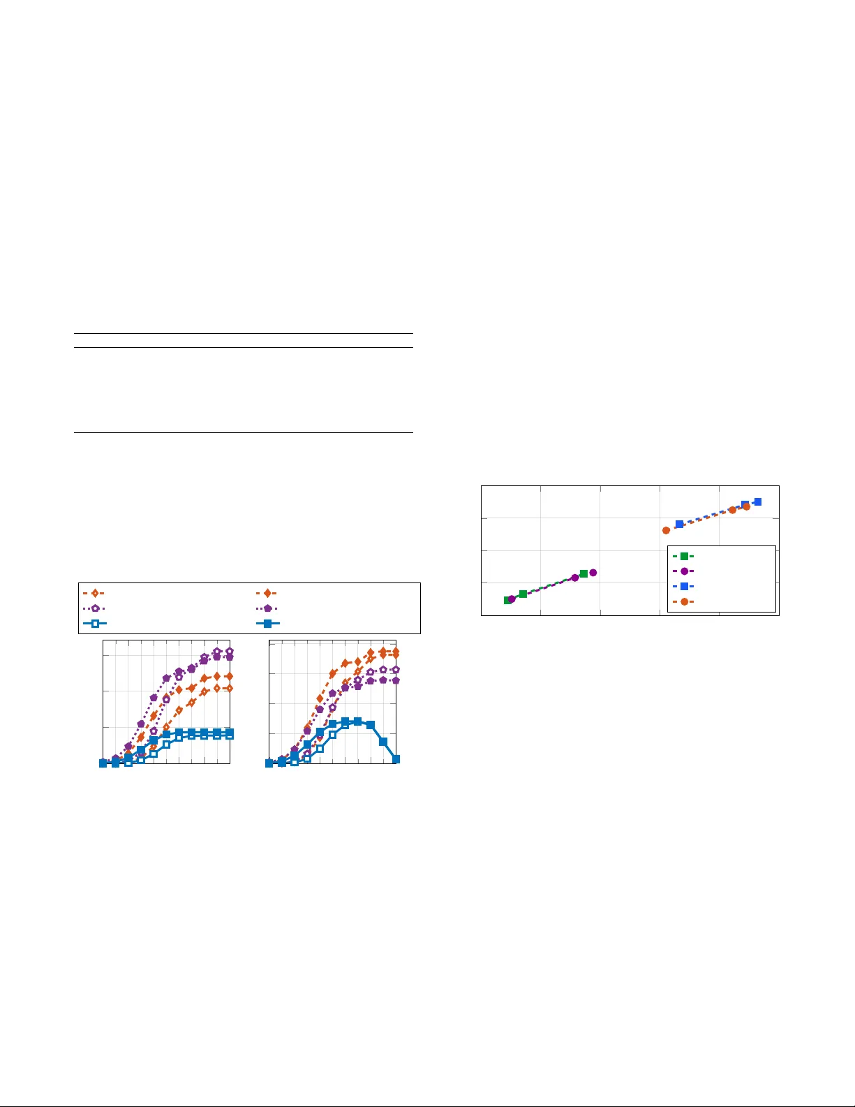
RIS-Assisted D-MIMO for Ener gy-Ef ficient 6G Indoor Networks Akshay V ayal Parambath 1 , Jose Flordelis 2 , V enkatesh T entu 1 , Charitha Madapatha 1 , Fredrik Rusek 2 , Erik Bengtsson 2 , T ommy Sv ensson 1 1 Department of Electrical Engineering, Chalmers Univ ersity of T echnology , Gothenburg, Sweden 2 Sony Europe, Lund, Sweden Abstract —W e pr opose an alternating optimization framework for maximizing energy efficiency (EE) in reconfigurable in- telligent surface (RIS) assisted distributed MIMO (D-MIMO) systems under both coherent and non-coherent reception modes. The framework jointly optimizes access point (AP) power al- location and RIS phase configurations to impro ve EE under per -AP po wer and signal-to-interference-plus-noise ratio (SINR) constraints. Using majorization-minimization for power alloca- tion together with per -element RIS adaptation, the framework achieves tractable optimization of this non-conv ex problem. Simulation results for indoor deployments with realistic power - consumption models show that the proposed scheme outperforms equal-power and random-scatterer baselines, with clear EE gains. W e evaluate the performance of both reception modes and quantify the impact of RIS phase-shift optimization, RIS controller ar chitectures (centralized vs. per -RIS contr ol), and RIS size, pr oviding design insights f or practical RIS-assisted D-MIMO deployments in future 6G networks. Index T erms —Distrib uted MIMO, RIS, energy efficiency , spec- tral efficiency , po wer allocation, alternating optimization, coher- ent and non-coherent r eception, 6G. I . I N T R O D U C T I O N A PPR O A CHING the sixth generation (6G) of wireless communications, the applications and use cases are rapidly expanding, leading to a sharp rise in the number of connected devices. Although macro base-station deployments act as the backbone of wireless networks, the y often struggle to meet user requirements and fairness as the network grows. T o balance these demands, more sophisticated architectures are needed to complement or extend existing infrastructure while ensuring efficient and sustainable operation [1]. Distributed MIMO (D-MIMO), also known as cell-free massiv e MIMO (CF-mMIMO), has emer ged as a promising paradigm, characterized by its adaptability and user-centric (UC) serving capability [2]. In such networks, distributed access points (APs) are dynamically clustered based on user positions, or channel conditions, lev eraging either estimated or measured channel state information (CSI). These UC clusters enable flexible AP coordination, improving key performance indicators such as throughput, co verage, and fairness. Despite these adv antages, D-MIMO systems still suf fer from severe cov erage degradation, especially in high-blockage indoor en- vironments [3]. Increasing AP density could mitigate this, but it is neither cost-efficient nor energy-efficient. This work was supported by the European Commission through the Horizon Europe/JU SNS project Hexa-X-II (Grant Agreement no. 101095759), and the Advanced Digitalization program at the WiTECH Centre DisCouRSe financed by VINNO V A, Chalmers, Ericsson, Qamcom, RISE, SAAB and V olv o Cars. Even with distributed multi-antenna APs, indoor D-MIMO remains constrained when direct AP-UE links are blocked or subject to se vere pathloss, as beamforming cannot bypass ob- stacles [3]. Reconfigurable intelligent surf aces (RISs) address this by enabling controllable reflections that form alternativ e paths without deploying additional APs [4]. Unlike network- controlled repeaters that rely on power -hungry amplify-and- forward relaying, RISs are nearly passive arrays of pro- grammable reflecting elements. By intelligently configuring their phase shifts, they align reflected signals with AP-UE links, thereby enhancing signal strength, suppressing interfer- ence, and improving link reliability at minimal po wer cost. W ith minimal hardware complexity and ease of deployment, RISs complement D-MIMO and serve as an energy-ef ficient alternativ e to AP densification in indoor en vironments. An additional challenge lies in the non-coherent (NC) reception inherent in D-MIMO systems, where signals from multiple APs may arrive phase-misaligned, disrupting coherent (C) combining and necessitating refined models that jointly optimize RIS configuration and power allocation under both C and NC reception. Here, coherent operation assumes that the serving APs coordinate their transmissions in both time and phase, enabling coherent signal combining at the UE. Sev eral approaches have attempted to address NC recep- tion in related architectures. For instance, mixed C and NC transmission strategies hav e been proposed to mitigate NC reception in CF-mMIMO-OFDM systems [5]. In addition, rate-splitting methods [6], hav e been explored to improv e SE in NC conditions. On the EE side, joint AP acti vation and power allocation for energy-efficient CF-mMIMO networks has been studied in [7]. These works highlight the challenges of NC reception and the importance of SE/EE optimization. Howe ver , most existing works either focus on NC reception in CF-mMIMO without RIS [5], [6] or consider EE optimization without jointly accounting for RIS-assisted C and NC recep- tion [7]. Our previous work [8] demonstrated the potential of RIS-assisted D-MIMO for improving indoor coverage and UC clustering. In that study , we showed that dynamic AP clustering combined with RIS assistance can significantly enhance signal-to-interference-plus-noise ratio (SINR), EE, and coverage probability . W e further rev ealed that RISs enable smaller AP clusters to achiev e performance comparable to larger clusters, highlighting RIS as a scalable and energy- efficient alternativ e to AP densification. Ho wev er, that study did not explicitly address NC reception nor formulated a joint EE optimization framew ork. Motiv ated by these gaps, this paper develops a joint alternat- ing optimization (A O) of RIS phase-shifts and transmit powers to maximize global EE in RIS-assisted D-MIMO systems. Unlike prior works, the proposed framework ev aluates the system under both C and NC reception while optimizing transmit power and RIS phase shifts for EE. A detailed power - consumption model is incorporated, including RIS controller and hardware power consumption, and the resulting EE serves as an upper-bound benchmark for practical implementations. Specifically , we incorporate 3GPP Indoor Hotspot (InH) chan- nel models [9]. T o address the resulting non-con vexity , the proposed A O framework combines majorization-minimization (MM)-based power allocation with RIS phase-shift adaptation. Through simulations, we benchmark the proposed approach against equal-po wer and random-scatterer RIS baselines, pro- viding insights into the roles of RIS optimization, controller architectures, and RIS size under both reception modes. Over- all, the findings show that RIS-assisted D-MIMO ef fectiv ely balances SE and EE, offering valuable guidance for future 6G wireless networks. I I . S Y S T E M M O D E L A. Network T opology and Associations Fig. 1: Illustration of an RIS-assisted D-MIMO downlink system. W e consider a narro wband RIS-aided D-MIMO downlink with L distributed APs, K single-antenna user equipments (UEs), and M RISs as illustrated in Figure 1. The APs are geographically distributed and connected via fronthaul links to a central processing unit (CPU) for UC coordination, joint precoder design, and RIS control. The deployment follows the 3GPP InH model [9], with APs uniformly placed on a grid with spacing D and of fset D/ 2 from the walls. The grid size ( L x , L y ) and spacing D are scenario dependent. The system operates at a carrier frequency f c and bandwidth B . The UEs are distrib uted following a finite homogeneous Poisson point process (FHPPP). Only a fraction of the K UEs are acti ve per schedul ing slot, reflecting realistic indoor traf fic loads (e.g., factory environments). Since AP locations are fixed, RIS panels are randomly deployed across the coverage area to support the spatially varying acti ve UEs and pro vide additional reflected paths in blocked regions. Each AP can serve up to N slot UEs per downlink time slot. Each acti ve UE k ∈ K act is jointly served by its two strongest APs, forming the cluster S k = { n 1 ( k ) , n 2 ( k ) } ⊆ L = { 1 , 2 , . . . , L } . An AP cluster size of tw o is used to keep the system model tractable while focusing on power allocation and RIS phase optimization. In addition, each UE is assisted by one RIS selected from M = { 1 , 2 , . . . , M } . The AP-UE clustering [2, 10], and UE-RIS association are based on large- scale fading and geometry , so that each UE selects the RIS offering the strongest cascaded AP-RIS-UE channel. The RIS size N RIS determines the passiv e beamforming gain; under ideal alignment, the reflected-signal po wer scales with N 2 RIS , thereby improving both SE and EE. B. Channel Model W e model each AP-UE, and AP-RIS-UE channel according to the 3GPP InH model [9, T able 7.4.1-1, 7.4.2-1], [11] as a Rician fading channel, which accounts for line-of-sight (LoS) probability , pathloss ( PL ), and shadowing in indoor scenarios. For a generic MIMO channel between a transmitter t with N t antennas and a receiv er r with N r antennas: H t,r = p β t,r q κ t,r κ t,r +1 a r ( θ r ) a H t ( θ t ) + q 1 κ t,r +1 W t , r , (1) where κ t,r is the Rician factor [9, T able 7.5-6], β t,r = G t G r 10 − PL( d 3D ,f c ) / 10 is the lar ge-scale fading (including antenna gains G t , G r ), a r ( θ r ) ∈ C N r × 1 and a t ( θ t ) ∈ C N t × 1 are the uniform linear array (ULA) steering vectors at AoA θ r and AoD θ t , respecti vely , and W t , r ∼ C N ( 0 , I N r ⊗ I N t ) is the Rayleigh component. For a ULA with N elements and half- wa velength spacing, the steering vector is given by a ( θ ) = 1 √ N [1 , e j π sin θ , . . . , e j π ( N − 1) sin θ ] T , where θ ∈ { θ t , θ r } . W e denote the AP-RIS channel by H n,m ∈ C N RIS × N AP , the RIS-UE channel by g m,k ∈ C N RIS × 1 , and the direct AP-UE channel by r n,k ∈ C 1 × N AP , which will be used in the subsequent signal model formulation. W e assume CSI is av ailable at the CPU for the considered indoor scenario with static users, while CSI acquisition is not addressed here. Each RIS m applies a diagonal unit-modulus phase-shift matrix Φ m = diag e j θ m, 1 , . . . , e j θ m,N RIS , where θ m,i ∈ [0 , 2 π ) . 1) Coher ent Case: In this case, all distrib uted APs are as- sumed to share a common phase reference, thereby achie ving network-wide synchronization. This allo ws their transmitted signals to be combined constructiv ely at the UE, provided that CSI is also well aligned, i.e., the relative phase offsets ∆ n,k between AP n and UE k are effecti vely zero. The propagation channel between AP n and UE k is h n,k ≜ g H m k ,k Φ m k H n,m k + r n,k , (2) where r n,k is the direct AP-UE link and the cascaded AP-RIS- UE contributions via the serving RIS m k are phase-aligned by appropriate choice of Φ m k . This model represents the best- case system performance, where RIS fully exploit their passi ve beamforming gain and signals from multiple APs combine coherently at the UE, yielding maximum array gain. While requiring significant synchronization overhead, this coherent case serves as an upper bound against which more practical schemes can be benchmarked. 2) Non-Coher ent Case: In distributed deployments, how- ev er , accurate phase synchronization across transmitting APs is rarely achie vable. Denoting the relati ve phase of fset between AP n and UE k as ∆ n,k = θ n − φ k , each transceiv er operates with its own oscillator, resulting in independent random phase offsets that are not known to the network [5]. The effecti ve channel can be expressed as ˜ h n,k ≜ e j ∆ n,k h n,k . (3) Here, the lack of phase alignment prevents coherent com- bining across APs, reducing the ov erall array gain and leading to lower SE and EE compared to the coherent case. C. Signal Model Let s k be the unit-po wer symbol for UE k , and p n,k ≥ 0 the transmit power from AP n to UE k . The transmit signal at AP n is x n = K X j =1 √ p n,j q n,j s j , (4) where q n,k ∈ C N AP × 1 denotes the precoder at AP n for UE k . The recei ved signal at UE k is y ( χ ) k = X n ∈S k √ p n,k h ( χ ) n,k q n,k s k + X j = k X n ∈S j √ p n,j h ( χ ) n,k q n,j s j + n k , (5) where the first term represents the desired signal for UE k , the second terms accounts for multi-user interference, and n k ∼ C N (0 , σ 2 k ) denotes the additiv e Gaussian noise with thermal noise variance σ 2 k . Here, we use χ ∈ { C , NC } to denote the reception type and write the effecti ve channel as h ( χ ) n,k . The instantaneous SE of UE k can be expressed as SE ( χ ) k = log 2 1 + P n ∈S k √ p n,k h ( χ ) n,k q n,k 2 P j = k P n ∈S j √ p n,j h ( χ ) n,k q n,j 2 + σ 2 k . (6) D. P ower-Consumption Model The total network power consumption in an RIS-assisted D- MIMO system is composed of the transmit power consumed by the power amplifiers (P As) and sev eral static hardware- related components. Let η P A ∈ (0 , 1] denote the P A effi- ciency . The dynamic transmit power required to deli ver the allocated per -UE powers { p n,k } with unit-norm precoders is P P A = 1 η P A P L n =1 P K k =1 p n,k . Follo wing [12], the static power contrib utions comprises: (i) transceiv er-chain po wer P TRxC , comprising one local oscillator (LO) per AP and the per-antenna RF power at APs and UEs, (ii) fixed per -AP ov erhead P FIX , and (iii) baseband signal-processing power P SP , scaling with B , L, N AP , K and in versely proportional to computational ef ficiency η AP - c . The RIS hardware also introduces a non-negligible cost, such that the total static power consumption is P static = P TRxC + P FIX + P SP + P RIS with P RIS = P M m =1 N RIS P b + P RIS - ctrl , where P b is the per-element biasing power [4, 13] and P RIS - ctrl accounts for the controller consumption [14]. For the considered indoor scenario with one RIS per UE ( M = K ), this expression scales linearly with K , and the controller term reduces to a single contrib ution when centralized RIS control is adopted. The overall network po wer consumption P tot is the sum of P P A and P static . This model highlights that although RISs introduce only lo wer P b , their controller architecture and the AP-side signal-processing complexity can dominate in the P static , thereby strongly influencing the achiev able EE. I I I . O P T I M I Z AT I O N F R A M E W O R K In this section, we first formulate the global EE maxi- mization problem for the RIS-assisted D-MIMO system. W e then introduce a compact ef fectiv e channel representation to simplify the SINR structure and motiv ate the need for problem reformulation. This leads to an EE objecti ve with power and SINR constraints, forming the basis for the MM-based A O algorithm dev eloped later . A. Effective Channel-Based Constants T o simplify the SINR analysis in (6), we rewrite the combined AP-RIS-UE channels into compact constants. This isolates desired signal and interference terms in (6), while keeping the optimization problem tractable. For a giv en UE k , let S k denote its serving APs and m k the associated RIS. The ef fectiv e channel from AP n t ( k ) to UE k , t ∈ { 1 , 2 } , combining direct and RIS-reflected paths, is C t,k = g H m k ,k Φ m k H n t ( k ) ,m k + r n t ( k ) ,k q n t ( k ) ,k . (7) Based on these effecti ve channels, the total desired-signal power for UE k can be expressed as A k ( p n,k , Φ m k ) = p 1 k C des 1 k + p 2 k C des 2 k + √ p 1 k p 2 k C des 3 k , (8) where C des 1 k = | C 1 ,k | 2 , C des 2 k = | C 2 ,k | 2 , and C des 3 k = 2 ℜ{ C 1 ,k C ∗ 2 ,k } , corresponding to the receiv ed power from each AP and their cross-term correlation. Interference from other users is modeled similarly . Let D ℓj,k denote the effecti ve interfering channel from AP n ℓ ( j ) (serving UE j ) to UE k . The total interference-plus-noise power is B k ( p n,k , Φ m k ) = X j = k p 1 j C int 1 j,k + p 2 j C int 2 j,k + √ p 1 j p 2 j C int 3 j,k + σ 2 k . (9) where C int 1 j,k = | D 1 j,k | 2 , C int 2 j,k = | D 2 j,k | 2 , and C int 3 j,k = 2 ℜ{ D 1 j,k D ∗ 2 j,k } . The resulting SINR for UE k is γ k ( p n,k , Φ m k ) = A k ( p n,k , Φ m k ) B k ( p n,k Φ m k ) . (10) B. Pr oblem F ormulation Using the SINR expression, the global EE maximization problem is formulated as in [7]. max { p n,k } , { Φ m k } EE( p n,k , Φ m k ) = B K P k =1 log 2 1+ γ k ( p n,k , Φ m k ) P tot s.t. p n,k ≥ 0 , K X k =1 p n,k ≤ P max n , ∀ n, k , γ k ( p n,k , Φ m k ) ≥ γ min k , ∀ k . (11) The first constraint limits each AP’ s total transmit power to P max n , ensuring per-AP power feasibility , while the second en- forces γ min k for each UE. This problem is challenging due to its fractional, non-con vex objecti ve and bilinear coupling between power allocation and RIS phases, making conv entional con vex methods unsuitable. Hence, we adopt an A O strategy , detailed in the ne xt section. Unlike power -minimization problems, the SINR constraints here need not hold with equality since the EE objectiv e inherently balances rate and power . C. Joint Alternating Optimization Algorithm W e tackle the EE maximization via an A O framework that alternately optimizes (i) po wer allocation using MM for fix ed RIS phases and (ii) RIS phase shifts for fixed powers. Iterative refinement of both variables enables efficient handling of the problem’ s non-conv exity . The compact SINR terms A k ( p ) and B k ( p ) from (8)-(9) are employed throughout. 1) MM-Based P ower Allocation (fixed Φ m k ): Given fixed RIS phases, transmit powers are optimized via MM by first con ve xifying the global EE objectiv e fraction, and then ap- plying a second MM step to approximate the SE term. At iteration t , auxiliary variables y ( t ) k are introduced to locally approximate the SINR in (10): y ( t ) k ≜ s A k ( p ( t ) n,k , Φ m k ) B k ( p ( t ) n,k , Φ m k ) , (12) SE ( t ) q k p ( t ) n,k , Φ m k ≜ log 2 1 + 2 y ( t ) k q A k ( p ( t ) n,k , Φ m k ) − ( y ( t ) k ) 2 B k ( p ( t ) n,k , Φ m k ) , (13) which locally approximates the SINR. T o address the frac- tional EE objective, a second MM step introduces a global auxiliary ratio ν ( t ) k that linearizes the SE-po wer coupling per iteration, defined as ν ( t ) ≜ P K k =1 r B SE ( t ) q k p ( t ) n,k , Φ m k P ( t ) tot . (14) The ratio ν ( t ) k is then updated from the current po wer and rate estimates to balance rate and P ( t ) tot in each MM iteration. After the MM reformulation, the objecti ve function remains non-con ve x due to the bilinear dependence of B k ( p ( t ) n,k , Φ m k ) on the transmit po wers, pre venting direct optimization. Thus, it is linearized around the current iterate p ( t ) n,k using a first-order T aylor approximation, yielding a con vex surrogate subproblem [15]. The resulting MM surrogate maximization problem is max { p n,k } 2 ν ( t ) k K X k =1 q B SE ( t ) q k p ( t ) n,k , Φ m k − ν ( t ) k 2 P tot ( p ( t ) n,k ) s.t. 2 y ( t ) k q A k ( p ( t ) n,k , Φ m k ) − ( y ( t ) k ) 2 B k ( p ( t ) n,k , Φ m k ) ≥ γ min k , p ( t ) n,k ≥ 0 , ∀ k , X k ∈K ℓ p ( t ) ℓk ≤ P max ℓ , ∀ ℓ, (15) where ν ( t ) k is the global auxiliary ratio. Solving this conv ex subproblem yields the updated po wers p ( t +1) n,k , ensuring non- decreasing EE across iterations. 2) RIS Phase Optimization (fixed powers): For a fixed power allocation, each RIS matrix Φ m k assisting UE k is up- dated to enhance the desired signal, as sho wn in Algorithm 1. After each update, the effecti ve channel constants A k ( · ) and B k ( · ) are recomputed, ensuring consistency with the new RIS configuration. This step exploits the passi ve beamforming gain of RIS while remaining computationally lightweight. 3) Outer Loop and Stopping Rule: The MM-based power allocation and RIS updates alternate until con vergence, i.e., until the global EE improvement between two consecutive outer iterations fall below a threshold ϵ , or when the max- imum iteration count is reached. This stopping rule ensures monotonic EE improvement and stable con vergence of the A O procedure. The full procedure is outlined in Algorithm 1. 4) Computational Complexity: In each outer A O iteration, the algorithm alternates MM-based power allocation and RIS phase optimization. Computing the auxiliary variables y ( t ) k and ν ( t ) in (12)-(14) has negligible complexity , while the dominant cost arises from solving the conv ex surrogate problem in (15). In the considered setup, each UE is served by two APs, giving n = 2 K real optimization variables. The surrogate problem includes K SINR, N per-AP power , and 2 K non-negati vity constraints, giving m = 3 K + N constraints. Using a standard interior-point method, the worst-case per-iteration comple xity is O ( n + m ) 3 / 2 n 2 = O (5 K + N ) 3 / 2 (2 K ) 2 . For fixed powers, RIS phase optimization uses per-element updates with linear complexity O ( K M ) per outer iteration, where M is the number of RIS elements. The total complexity scales linearly with the number of outer A O iterations T outer . Algorithm 1 A O Framework for EE Maximization Input: Channel gains; { n 1 ( k ) , n 2 ( k ) } ; { γ min k } ; σ 2 ; { P max ℓ } ; P static ; B ; max inner/outer iters T , T outer ; K . Output: Final power allocation p ( t +1) n,k and Φ m k . 1: Initialize: Set p (0) n,k = p 0 n,k , ¯ EE (0) = −∞ 2: f or n = 1 to T outer do ▷ Outer A O loop 3: —MM-Based P ower Optimization (fixed RIS phases)— 4: for t = 0 to T − 1 do 5: Compute A ( t ) k , B ( t ) k , y ( t ) k , SEeq ( t ) k , and ν ( t ) 6: Solve surrogate problem in Eq. (15) 7: Let p ( t +1) n,k ← optimal solution of surrogate 8: Update p ( t ) n,k ← p ( t +1) n,k 9: if con vergence met then break 10: end if 11: end for 12: —RIS Phase Optimization (fixed powers)— 13: for k = 1 to K do 14: Load fixed { q 1 ,k , q 2 ,k } and { p ( t +1) 1 k , p ( t +1) 2 k } 15: repeat 16: Compute g k = g H 1 ,k , h k = H 1 , 1 q 1 ,k + H 2 , 1 q 2 ,k 17: Update Φ m k = − ∠ ( g k h k ) 18: Apply phase correction θ = ∠ ( r 1 ,k q 1 ,k ) 19: Update cascaded channel with Φ m k 20: until con vergence 21: Sav e Φ m k and Update P rx k = P ℓ ∈L k p ( t +1) ℓk | r ℓ,k q ℓ,k | 2 + | g 1 ,k Φ m k H ℓ, 1 q ℓ,k | 2 22: Recalculate channel gains using updated Φ m k for UE k 23: end for 24: Compute EE ( n ) 25: if n > 1 and ¯ EE ( n ) − ¯ EE ( n − 1) < ϵ then break ▷ Conv erged 26: end if 27: end for I V . P E R F O R M A N C E E V A L UA T I O N A. Simulation Setup W e consider a 300 × 150 m 2 indoor area where L APs are uniformly deployed following the 3GPP InH model. The system operates at f c = 4 GHz with B = 20 MHz. Each AP ( N AP = 4 ) serves up to N slot = 4 UEs per time slot. A total of K = 100 single-antenna UEs are distributed following a FHPPP , with 10% activ e UEs per slot. Each acti ve UE k ∈ K act is associated with its two strongest APs, forming a UC cluster S k ⊆ L . W e deploy M = 10 RIS panels, each with N RIS elements, randomly placed in the area, independent of the AP grid. Each UE is assisted by one av ailable RIS applying a diagonal unit-modulus reflection matrix, where each element- wise phase shift θ m,i ∈ [0 , 2 π ) . This RIS control provides an upper bound to practical codebook-based approaches. Each AP’ s transmit power is limited by P max ℓ , and σ 2 is obtained from noise power spectral density of N 0 = -174 dBm/Hz ov er B . W e set γ min k = 0 to study intrinsic SE-EE behavior without explicit quality-of-service constraints, since enforcing positiv e SINR targets for all users may lead to infeasibility under the considered deployment and po wer constraints. The proposed framew ork is ev aluated via Monte Carlo simulations, and remaining parameters are listed in T able I. T ABLE I: Simulation Parameters Parameter V alue L, N RIS , N UE , κ 9, 256 (per RIS), 1, 5 dB Antenna gains G TX , G RX , G RIS 5 dB, 2 dB, 4 dB Shadowing χ LoS , χ NLoS 3 dB, 8.03 dB P FIX , P LO 0.875 W , 0.1 W (per AP) P AP - ant , P UE - ant 0.2 W , 0.1 W (per antenna) η P A , P b , P RIS - ctrl , η AP - c 0.4, 0.997 mW , 4.8 W , 750 Gflop/s B. Results & Discussion T o show the effectiv eness of the proposed joint A O, we ev aluate global EE and sum SE under v arious baselines and system settings. W e study the (i) benefits of RIS integration, AP density v ariations, and baseline comparisons of po wer al- location and reception models; (ii) gain of joint transmit power and RIS phase optimization; (iii) impact of RIS controller power consumption models; and (iv) ef fect of RIS size. − 50 − 30 − 10 10 30 50 0 20 40 60 P T (dBm) Sum SE (bps/Hz) − 50 − 30 − 10 10 30 50 0 10 20 30 40 P T (dBm) Global EE (Mbps/J) RIS Absent, OP A, C ( L =9) RIS Activ e, OP A, C ( L =9) RIS Absent, OP A, C ( L =18) RIS Activ e, OP A, C ( L =18) RIS Absent, EP A, NC ( L =9) RIS Activ e, EP A, NC ( L =9) Fig. 2: Sum SE and global EE vs. P T for a D-MIMO system, com- paring benchmarks of RIS integration, and global EE optimization. 1) SE and EE Behavior: Figure 2 sho ws the sum SE and global EE versus P T 1 . First, optimized power allocation (OP A) consistently outperforms equal power allocation (EP A), particularly at medium and high P T . The MM-based method adapts transmit power to channel conditions by f av oring strong links while a voiding excess po wer on weaker ones once their SE contribution saturates. As a result, OP A a voids unnecessary transmit po wer increases after SE saturation, preserving ener gy 1 T ypical indoor AP transmit powers are below 30 - 35 dBm. Higher transmit power values are considered here only to illustrate EE-SE trends over a wider operating range, as used in Figures 2, 3, and 5. and sustaining EE gains. In contrast, EP A uniformly distributes P T across UEs, wasting po wer on weaker links and causing early EE saturation or decline at high P T . The EE gap is therefore more pronounced due to inefficient power use. Second, RIS optimization and AP densification reveal clear performance trade-of fs. When RISs are absent, both SE and EE plateau early since UEs rely solely on direct AP-UE links. Activ ating RISs with optimized phase-shifts (RIS-Opt) i.e., RIS Active, strengthens the effecti ve channel, particularly at moderate P T , where reflected paths contrib ute most. Increasing L from 9 to 18 improv es SE, but the added APs increase total power consumption, slightly reducing EE. At high P T , the EE gap narrows between RIS Active and RIS Absent cases with OP A and C combining for L = 9 , despite higher SE with RIS Activ e. This indicates that beyond a certain P T , EE gains from RIS integration diminish as P tot dominates, while higher P T still yield moderate SE gains from RIS and AP densification. Third, the reception model significantly affects performance. C combining achiev es the highest SE and EE by enabling coherent signal addition across APs. NC combining, while simpler to implement, yields lo wer performance since signals add only in power domain. Nevertheless, with RIS Activ e, NC still outperforms the RIS Absent case, sho wing that RISs remain beneficial ev en without perfect synchronization. 25 30 35 40 45 50 20 25 30 35 40 Sum SE (bps/Hz) Global EE (Mbps/J) RIS–Rand, C RIS–Rand, NC RIS–Opt, C RIS–Opt, NC Fig. 3: Global EE vs. sum SE for a RIS-assisted D-MIMO system ( L = 9, N RIS = 256) under C and NC reception, comparing RIS-Opt and RIS-Rand with OP A across P T ∈ [20 , 40] dBm. 2) Joint T ransmit P ower and RIS Phase-shift Optimiza- tion Significance: Figure 3 sho ws the global EE-sum SE tradeoff for RIS-assisted D-MIMO networks with OP A at P T ∈ { 20 , 30 , 40 } dBm. The comparison with random- scatterer (RIS-Rand) baselines under both C and NC reception show that RIS-Opt provides consistent performance gains across all operating points. W ith RIS-Opt, reflected links constructiv ely combine with direct AP-UE channels, enabling higher SE and translating into impro ved EE. In contrast, RIS- Rand results in weaker effecti ve channels and lower EE for a giv en SE. Furthermore, the performance gap between C and NC reception is marginal, indicating that RIS-Opt with OP A remains effecti ve ev en without coherent combining. Howe ver , in both reception models, the relative gain of RIS-Opt o ver RIS-Rand remains e vident. These results highlight that RIS optimization is critical for unlocking the full EE potential of RIS-assisted D-MIMO systems. 3) RIS Contr oller P ower Consumption Models: Figure 4 ev aluates the impact of RIS controller power at P T = 30 dBm using optimized transmit power and RIS-Opt. W e compare a centralized controller (shared, P RIS - ctrl = 4.8W) [14] with per- RIS controllers having P RIS - ctrl ∈ { 2 . 8 , 3 . 8 , 4 . 8 } W under C and NC combining. The centralized option attains the highest EE since its o verhead is ef fectiv ely independent of M . For per - RIS control, EE decreases monotonically with P RIS - ctrl as the static power scales with M . Among per-RIS controllers, the 2.8 W case achiev es the highest EE, whereas 3.8-4.8 W yield noticeably lower EE. Across architectures, the C/NC ordering is consistent, but controller power dominates EE, fav oring centralized or low-po wer per -RIS control as M increases. Central ( 4 . 8 W) Per-RIS ( 2 . 8 W) Per-RIS ( 3 . 8 W) Per-RIS ( 4 . 8 W) 0 10 20 30 40 37.0 19.2 16.0 13.6 36.2 18.8 15.6 13.3 Global EE (Mbps/J) C NC Fig. 4: Global EE of a RIS-aided D-MIMO system ( L = 9 , N RIS = 256 ) under C and NC combining for centralized and per-RIS control. 4) Effect of RIS Size: Figure 5 illustrate that increasing N RIS enhances EE in the lo w-to-moderate power range due to stronger passiv e beamforming, though with diminishing returns; the gain from 128 to 256 elements is evident, while the improvement from 256 to 512 is modest. As P T increases further , the total po wer in the EE denominator grows faster than the achiev able SE gain, leading to earlier EE saturation. As the RIS panel size increases, the higher static power outweighs the limited additional beamforming gain, resulting in only marginal benefits. At higher P T , the N RIS = 256 case con verges with the 128-element curve, while the 512- element case falls slightly below both, indicating reduced energy efficienc y for excessiv ely lar ge panels. The C/NC ordering remains consistent, with C combining forming the upper en velope across all considered N RIS configurations. − 20 − 10 0 10 20 30 40 50 0 10 20 30 40 P T (dBm) Global EE (Mbps/J) N RIS = 512 , C N RIS = 512 , NC N RIS = 256 , C N RIS = 256 , NC N RIS = 128 , C N RIS = 128 , NC Fig. 5: Global EE vs. P T for a RIS-assisted D-MIMO system with L = 9 APs, under C and NC reception using OP A and RIS-Opt. V . C O N C L U S I O N This work inv estigated energy-efficient transmission in RIS- aided D-MIMO systems using a joint A O framework al- ternating MM-based power allocation and RIS phase-shift optimization. The ef fectiv e-channel formulation enables effi- cient surrogate optimization of the non-con vex EE problem. Simulation results re veal that OP A outperforms EP A, with EE peaking at moderate P T . RIS assistance improves both SE and EE, with RIS-Opt consistently outperform RIS-Rand under both combining modes, especially at moderate P T . RIS controller po wer is critical as centralized control achie ves the highest EE, whereas per-RIS control is comparable only at low controller power; higher per-RIS budgets degrade EE as M grows, emphasizing the importance of hardware-aw are system design. Scaling N RIS improv es EE with diminishing returns, as most gains are captured by medium size panels, and at high P T very large panels add only marginal EE. Finally , C combining forms the upper bound, while NC combining remains effecti ve with RIS phase optimization and adaptiv e power control. Overall, the results highlight that both signal processing algorithms and hardware architecture play pi votal roles in determining the EE of RIS-aided D-MIMO networks. Future work may extend the proposed framework to wideband sys- tems to further assess the scalability of energy ef ficient D- MIMO architectures. Such an extension introduces challenges related to frequency-selecti ve channels, RIS bandwidth limi- tations, and increased channel estimation and synchronization ov erhead, which may impact overall ener gy efficienc y . R E F E R E N C E S [1] G. Interdonato et al. , “Ubiquitous cell-free massiv e MIMO communi- cations, ” EURASIP J. on W ir eless Commun. and Netw . , vol. 2019, pp. 1–13, 2019. [2] E. Bj ¨ ornson and L. Sanguinetti, “Scalable cell-free massive MIMO systems, ” IEEE T rans. Commun. , vol. 68, no. 7, pp. 4247–4261, 2020. [3] M. Di Renzo et al. , “Smart radio environments empowered by reconfig- urable intelligent surfaces: How it works, state of research, and the road ahead, ” IEEE J. Sel. Areas Commun. , vol. 38, no. 11, pp. 2450–2525, 2020. [4] C. Huang et al. , “Reconfigurable intelligent surfaces for energy effi- ciency in wireless communication, ” IEEE T rans. W ireless Commun. , vol. 18, no. 8, pp. 4157–4170, 2019. [5] G. Li et al. , “ Asynchronous cell-free massiv e MIMO-OFDM: Mixed coherent and non-coherent transmissions, ” IEEE Commun. Lett. , 2024. [6] J. Zheng et al. , “ Asynchronous cell-free massi ve MIMO with rate- splitting, ” IEEE J. Sel. Areas Commun. , vol. 41, no. 5, pp. 1366–1382, 2023. [7] T . V an Chien et al. , “Joint power allocation and load balancing opti- mization for energy-ef ficient cell-free massive MIMO networks, ” IEEE T rans. W ireless Commun. , vol. 19, no. 10, pp. 6798–6812, 2020. [8] A. V . Parambath et al. , “Integrating reconfigurable intelligent surfaces (riss) into indoor D-MIMO networks for 6G, ” in Pr oc. IEEE VTC2024- F all , 2024, pp. 1–6. [9] ETSI, “5G; study on channel model for frequencies from 0.5 to 100 GHz (3GPP TR 38.901 version 16.1.0 release 16), ” T ech. Rep., 2020. [Online]. A v ailable: https://www .etsi.org/deliv er/etsi tr/138900 138999/138901/16.01.00 60/tr 138901v160100p.pdf [10] Q. Y e et al. , “User association and interference management in massive MIMO HetNets, ” IEEE T rans. Commun. , vol. 64, no. 5, pp. 2049–2065, 2016. [11] W . W ang and E. S. Lohan, “ Applicability of 3GPP indoor hotspot models to the industrial environments, ” in Pr oc. IEEE ICL-GNSS , 2018, pp. 1–5. [12] E. Bj ¨ ornson et al. , “Massiv e MIMO networks: Spectral, energy , and hardware efficienc y , ” F oundations and T rends® in Signal Processing , vol. 11, no. 3-4, pp. 154–655, 2017. [13] V . T entu et al. , “UA V-enabled hardware-impaired spatially correlated cell-free massive MIMO systems: Analysis and energy efficiency opti- mization, ” IEEE T rans. Commun. , vol. 70, no. 4, pp. 2722–2741, 2022. [14] J. W ang et al. , “Static power consumption modeling and measurement of reconfigurable intelligent surfaces, ” in Proc. IEEE EUSIPCO , 2023, pp. 890–894. [15] S. Boyd and L. V andenber ghe, Conve x Optimization . Cambridge Univ ersity Press, 2004. [Online]. A vailable: https://web.stanford.edu/ ∼ boyd/cvxbook/bv cvxbook.pdf
Original Paper
Loading high-quality paper...
Comments & Academic Discussion
Loading comments...
Leave a Comment