Gaussian Phase Noise Effects on Hybrid Precoding MIMO Systems for Sub-THz Transmission
The sub-THz spectrum offers numerous advantages, including massive multiple-input multiple-output (MIMO) technology with large antenna arrays that enhance spectral efficiency (SE) of future systems. Hybrid precoding (HP) thus emerges as a cost-effect…
Authors: Yaya Bello, Yahia Medjahdi, Laurent Clavier
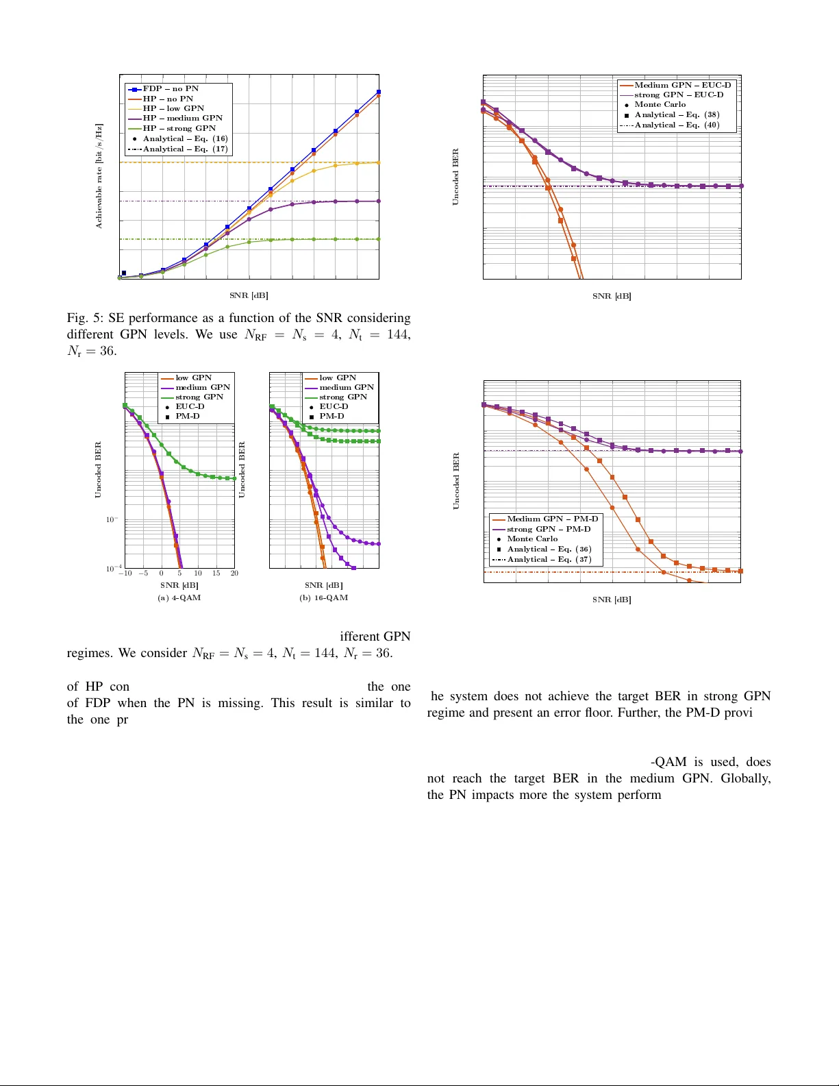
Gaussian Phase Noise Ef fects on Hybrid Precoding MIMO Systems for Sub-THz T ransmission Y aya Bello 1 , Y ahia Medjahdi 1 , Laurent Clavier 1,2 , Arthur Louchart 1 , 1 IMT Nord Europe, Institut Mines T ´ el ´ ecom, Center for Digital Systems, F-59653 V illeneuve d’Ascq, France 2 Inria, V illeneuve d’Ascq, France Email: yaya.bello@imt-nord-europe.fr Abstract —The sub-THz spectrum offers numerous advantages, including massive multiple-input multiple-output (MIMO) tech- nology with large antenna arrays that enhance spectral efficiency (SE) of future systems. Hybrid precoding (HP) thus emerges as a cost-effective alter native to fully digital pr ecoding regarding complexity and energy consumption. Howev er , sub-THz frequen- cies introduce hardware challenges, particularly phase noise (PN) from local oscillators (LOs). W e analyze PN impact on MIMO systems using HP , leveraging singular value decomposition and common LO architectur e. W e adopt the Gaussian PN (GPN) model, recognized as accurate for describing PN behavior in sub- THz transmissions. W e derive a lower bound on achievable SE and pro vide closed-form bit error rate expressions for quadra- ture amplitude modulation (QAM)—specifically 4-QAM and 16- QAM—under high-SNR and strong GPN conditions. These ana- lytical results are validated through Monte Carlo simulations. W e show that GPN can be effectively counteracted with a single pilot symbol in single-user MIMO systems, unlike single-input single- output systems where mitigation pro ves infeasible. Simulation results compare con ventional QAM against polar -QAM tailored for GPN-impaired systems. Finally , we introduce perspectives for further improvements in performance and energy efficiency . Index T erms —Hybrid precoding, Massive MIMO, Phase Noise, Sub-THz, Beyond 6G. I . I N T RO D U C T I O N T O meet the sur ging demand for high-speed multime- dia, wireless capacities must increase exponentially [1]. Future architectures tar get an approximate thousand-fold in- crease w .r .t. 5G impro vements [2]. K ey strate gies include: (i) boosting physical (PHY) layer spectral ef ficiency (SE) via massiv e multiple-input multiple-output (MIMO) [3], and (ii) expanding bandwidth. Spectrum scarcity in contemporary cellular infrastructures constitutes a critical limiting factor that fundamentally constrains any prospective enhancement in net- work capacity . Frequenc y bands in the sub-terahertz (sub-THz) range, specifically spanning from 90 GHz to 300 GHz, hav e recently emerged as leading candidates for additional spectrum resources for the next generation of cellular systems [4]. These bands of fer the prospect of exceptionally large contiguous bandwidths and thus enabling unprecedented data throughput capabilities [5]. Howe ver , transmitting in this frequency band presents se veral obstacles, such as huge channel path loss, high sampling frequency required from digital-to-analog (D A C) and analog-to-digital (ADC) con verters, and the phase noise (PN) generated by the local oscillator (LO) at both the transmit- ter (Tx) and receiv er (Rx) [6]. Owing to the intrinsically short wa velength of millimeter-wav e (mmW a ve) signals, sub-THz MIMO precoding could exploit v ery large-scale antenna arrays at the Tx and Rx to achieve substantial beamforming gains. These gains effecti vely mitigate sev ere propagation losses while enabling the synthesis of highly directional transmission beams [7]–[9]. In con ventional MIMO architectures, precoding operations are predominantly executed digitally within the baseband, enabling precise control over both amplitude and phase com- ponents of transmitted signals [10]. Nev ertheless, implement- ing fully digital precoding (FDP) necessitates the deployment of a radio frequency (RF) chain for each antenna element, encompassing components such as mixers and ADC/D A C con verters. Although the diminutiv e wav elengths characteristic of sub-THz bands facilitate the integration of very large antenna arrays, the substantial cost and po wer consumption associated with equipping each element with a dedicated RF chain renders FDP impractical [11], [12]. T o address these constraints inherent in mmW av e MIMO systems, hybrid pre- coding (HP) framew orks hav e attracted considerable research interest [13]–[15]. Such architectures strategically combine a reduced number of RF chains interfacing a low-dimensional digital precoder with a high-dimensional analog precoder , thereby enabling ef ficient utilization of hardware resources while achieving near-optimal precoding performance. PN originates from rapid, stochastic fluctuations in the phase of an oscillator signal induced by intrinsic device components. These short-term random phase variations disrupt the temporal stability of the w av eform, leading to performance degrada- tion [16]. Furthermore, PN can manifest as synchronization challenges in digitally clocked and sampled-data systems. The sev erity of PN escalates with increasing carrier frequency , thereby posing significant detriments to system reliability and efficienc y , particularly in transmissions at sub-THz fre- quency ranges. Fundamentally , PN arises as the composite effect of multiple random processes. Some exhibiting tem- poral correlation, such as the W iener process, and others uncorrelated, ex emplified by additiv e white Gaussian noise. In the literature, models incorporating correlated behavior , including the W iener PN model and the standardized 3GPP PN framew ork, hav e been extensi vely adopted [17]–[19]. The correlated component of PN can, in principle, be tracked and subsequently compensated to mitigate its degradation of radio link performance [20]. Nev ertheless, as large signal bandwidths are feasible within sub-THz frequency regimes, the influence of the residual uncorrelated Gaussian PN (GPN) component becomes predominant, thus posing a more critical limitation on system performance [21]. In MIMO systems, two LO architectures are possible: (i) common LO (CLO), where all RF chains share a centralized LO, and (ii) independent LO (ILO), where each RF chain uses its o wn LO. As reported in [22]–[24], the ILO archi- tecture is less impacted by PN than the CLO configuration. Consequently , we in vestigate in this work the GPN effect on HP single-user MIMO (SU-MIMO) systems in terms of achiev able rate and derive closed-form bite error rate (BER) expressions in high SNR and strong GPN regimes focusing on CLO architecture. A. Related W orks The PN impact in HP MIMO systems has been inv estigated using both W iener PN models [25]–[27] and GPN models [28], [29]. In [25], the authors highlighted the PN ef fect in multi- user MIMO systems employing zero-forcing (ZF) precoding for downlink transmission under a CLO architecture. They de- riv ed a lower bound on the achie v able rate based on the chan- nel covariance matrices used for channel estimation during the uplink transmission. Ho wev er, utilizing the ZF precoder re- quires the number of RF chains to match the number of users, which, from an energy consumption perspecti ve, degrades en- ergy efficienc y (EE). In [26], the authors proposed se veral PN estimation techniques for PN compensation, with the aim of enhancing the performance of a SU-MIMO system operating with ILO architecture. They assumed perfect channel state information (CSI) knowledge, and HP matrices were designed following the approach presented in [30]. In [28], the authors demonstrated the performance degradation of HP SU-MIMO systems employing singular value decomposition (SVD) pre- coding in the presence of GPN. In [29], they further examined the impact of channel estimation errors and GPN on system performance, assuming fixed analog beamforming matrices to reduce design complexity . Unfortunately , no theoretical expressions of the achie v able rate or BER are deri ved in [28], [29]. Although GPN is considered the most suitable model for describing PN ef fects in sub-THz transmissions [21], relati vely few papers in the literature address its impact on HP MIMO systems. T o the best of our knowledge, no analytical BER expression has been derived for SVD-based HP SU-MIMO systems af fected by GPN. This work therefore contributes such an analysis. B. Contributions The paper highlights the following contributions: • Derive and analyze the theoretical e xpression of the lower bound on the achie vable SE of HP SU-MIMO in the presence of GPN. • Provide semi-analytical BER expressions of HP SU- MIMO in the presence of GPN for both quadrature amplitude modulation (QAM) especially 4-QAM and 16- QAM, and polar-QAM (PQAM) constellation schemes. Digital Precoder Analog Precoder DAC DAC Fig. 1: HP massiv e MIMO Tx system model considering CLO architecture. • Propose closed-form expressions of the a verage BER in high-SNR and strong GPN regimes and validate them via Monte Carlo simulations. • Formulate semi-analytical e xpressions of the sum rate and of the BER when PN is alleviated. • Inv estigate and compare the system performance between con ventional QAM modulation scheme and PQAM con- stellation, both with and without PN cancellation. C. Organization The remainder of the paper is as follows. Sec. II and Sec. III present the system model and the various closed-form expressions of the achie vable SE and BER, respectiv ely . The simulation results are carried out in Sec. IV, discussions and perspectiv es are figured out in Sec. V. W e end up with the conclusion in Sec. VI. D. Notations Higher boldface letters A denote matrices and lower bold- face letters a indicate column vectors where the scalar a k is its k th element. The term a k ρ (resp. a k θ ) denotes the magnitude v alue (resp. phase value) of the scalar a k . The term E {·} denotes the expectation operator . The operators |·| , arg {·} , Re {·} , Im {·} , ( · ) T , ( · ) ∗ , ( · ) H , ∥ · ∥ and ∥ · ∥ F return respecti vely the magnitude, the phase, the real part, the imaginary part, the transpose, the conjugate, the Hermitian, the Euclidean norm and the Frobenius norm v alue of the ar gument. A Gaussian (resp. a complex Gaussian) random v ariable d is denoted d ∽ N ( m, q ) (resp. d ∽ C N ( m, q ) ), where m is the mean and q is the v ariance. A circular symmetric complex Gaussian random vector d is denoted d ∽ C N ( m , T ) , where m is the mean and T is the cov ariance matrix. The term I X stands for the identity matrix of size X . Finally , j ≜ √ − 1 defines the unit imaginary number . I I . S Y S T E M M O D E L A. Channel and PN Models The propagation environment in sub-THz frequencies is expected to be typically sparse thanks to the use of high gain and directive antennas focusing the energy in the desired direction and thereby , reduce multipath. W e consider the Saleh-V alenzuela model which is the most commonly used channel model in mmW ave transmissions [31]–[34] due to very high free-space path loss. Therefore, by assuming a half- wa ve spaced uniform linear array at both the Tx and Rx, the channel matrix H of size N r × N t is defined by [35] H = r N t N r N c N R N c X i =1 N R X l =1 ξ il a r ( θ r il ) a t θ t il H , (1) where N r , N t , N c and N R are the number of receive antennas, the number of transmit antennas, the number of clusters and the number of rays within each cluster , respecti vely . The term ξ il ∼ C N (0 , 1) denotes the complex channel gain of the l th ray in the i th propagation cluster . The vectors a r ( θ r il ) and a t ( θ t il ) represent the normalized responses of the transmit and receiv e antenna arrays, respectively , which are defined by a r ( θ r il ) = 1 √ N r h 1 e j π sin θ r il · · · e j π ( N r − 1) sin θ r il i T , a t θ t il = 1 √ N t h 1 e j π sin θ t il · · · e j π ( N t − 1) sin θ t il i T , (2) where θ r il and θ t il stand for the angle of arri val (AoA) and departure (AoD), respectiv ely . As long as the PN increases with the carrier frequency , the influence of the uncorrelated GPN component becomes dominant with the increase of the signal bandwidth. Thus, we consider a GPN model where the k th PN sample generated at the i th RF chain is modeled by ϕ i [ k ] ∼ N 0 , σ 2 ϕ and φ i [ k ] ∼ N 0 , σ 2 φ , (3) where σ 2 ϕ and σ 2 φ denote the GPN variance at the Tx and Rx, respectiv ely . Three GPN lev els are considered: strong GPN for σ 2 ψ = 10 − 1 , medium GPN for σ 2 ψ = 10 − 2 and lo w GPN for σ 2 ψ = 10 − 3 assuming σ 2 ψ = σ 2 ϕ + σ 2 φ with σ 2 ϕ = σ 2 φ . Finally , we adopt a coherent Rx design, i.e. , with perfect synchronization in both time and frequency . B. HP SU-MIMO Systems with CLO Arc hitectur e In this paper , we consider a SVD-based HP SU-MIMO system under CLO scheme where all the RF chains share the same LO as figured out in Fig. 1 1 . Regarding analog precoding, the mapping configuration between RF chains and antenna elements determines the required number of phase shifters (PSs). Based on this configuration, HP transceiv er ar- chitectures can be broadly classified into two categories: fully- connected (FC) and partially-connected (PC) topologies, as depicted in [30]. W e consider the FC architecture where each RF chain interfaces with all antenna elements via a complete network of PSs, thereby enabling maximum beamforming gain and improved array directivity . For the analog precoding and combining design, we assume the low complexity algorithm named phase extraction-AltMin (PE-AltMin) [30] achie ving performance le vels almost similar to those of FDP systems in terms of SE when the number of RF chain N RF is equal to the number of data stream N s as considered in this work. 1 Obviously , the Rx system model is the reverse of the processing steps performed at the Tx. Sharing the same LO leads to a same PN process on any RF chain, i.e. , ∀ i ∈ { 0 , N RF − 1 } , ϕ i = ϕ and φ i = φ · (4) Therefore, the receiv ed signal expression is giv en by r PN = e j ( ϕ + φ ) U H BB W H RF HF RF F BB s + e j φ U H BB W H RF n = e j ψ Vs + e j φ U H BB W H RF n , (5) where V = U H BB W H RF HF RF F BB . The terms F BB and F RF denote the digital precoder matrix of size N RF × N s and the analog precoder matrix of size N t × N RF , respectiv ely . The terms U BB and W RF are the digital decoder matrix of size N RF × N s and the analog decoder matrix of size N r × N RF , respectiv ely . The term s represents the transmitted signal such that s ∼ C N ( 0 , I N s ) and, n ∼ C N 0 , σ 2 I N r denotes the thermal noise which is independent and identically distributed. The term ψ = ϕ + φ ∼ N 0 , σ 2 ψ = σ 2 ϕ + σ 2 φ stands for the sum of the PN processes. I I I . D E R I V A T I O N O F B I T E R RO R R AT E A N D A C H I E V A B L E R A T E E X P R E S S I O N S In this section, we derive the theoretical lo wer bound e xpres- sion on the achie vable SE. W e also provide semi-analytical and closed-form BER expressions of SVD-based HP SU-MIMO systems with and without GPN. A. HP Systems without PN Let us express the recei ved signal at the k th stream without PN by r k = u BB H k W H RF HF RF f BB k s k + N s X i =1 ,i = k u BB H k W H RF HF RF f BB i s i + u BB H k W H RF n , (6) where u BB k and f BB k denote the k th column of U BB and F BB , respectiv ely . The second term in (6) represents the inter-stream interference (ISI), i.e . , the interference of the other streams on the stream k . Despite the optimality of analog/digital precoders and decoders put forward in [30], the BER performance of the HP system is limited since the optimization criterion does not take into account the error minimization. Sev eral works emerged and introduced new algorithms for hybrid precoders and decoders regarding the BER minimization [34], [35]. Nevertheless, these algorithms bring more computational complexity . In this work, we consider, as suggested in [28], [29], that the digital precoder and decoder are deriv ed from the SVD of the equi v alent channel H eq = W H RF HF RF = U BB VF H BB . Thus, the matrix V represents the diagonal matrix of singular values of the matrix H eq and therefore the ISI term P N s i =1 ,i = k u BB H k H eq f BB i s i = 0 · Additionally , since the objective is to achiev e the same SE performance as in FDP , the digital precoder F BB is normalized by a factor ρ = √ N s ∥ F RF F BB ∥ F in order to ensure that the signal power after the two precoding stages (digital and analog) remains equal to the signal power after the digital precoder F opt . Thus, by posing H eq = W H RF HF RF , the expression (6) becomes r k = ρ u BB H k H eq f BB k s k + u BB H k W H RF n = ρ V k,k s k + n ′ , (7) where V k,k = u BB H k H eq f BB k represents k th singular value of H eq and also the element at the k th row and column of the diagonal matrix V . The vector n ′ = u BB H k W H RF n denotes the thermal noise after the analog and digital combining matrices. Therefore, the achiev able sum rate can be giv en as a function of the signal-to-noise ratio (SNR) at the k th stream named β k by R = N s X k =1 R k = N s X k =1 log 2 (1 + β k ) , (8) where β k is defined by β k = ρ 2 | V k,k | 2 σ 2 ξ k , (9) where ξ k = u BB H k W H RF W RF u BB k . Using SVD approach giv en the perfect CSI kno wledge allows to decouple the MIMO channel into N s independent SISO channels as highlighted in (7). In this setting, an exact semi-analytical BER expression for a M -ary QAM constellation, where M denotes the modu- lation order , can be deduced for a given channel assuming an optimal detection as follows [36], [37] P be = 4 N s √ M log 2 ( M ) N s X k =1 log 2 √ M X p =1 ( 1 − 2 − p ) √ M − 1 X c =0 ( ( − 1) j c · 2 p − 1 √ M k 2 p − 1 − c · 2 p − 1 √ M + 1 2 Q s 3 (2 c + 1) 2 β k M − 1 ) , (10) where Q ( · ) represents the Q-function. The semi-analytical BER expression in (10) depends on the SNR β k instead of the SNR at the receiv e antennas (before the analog combining or decoding). Thankfully , the relationship between the two terms is giv en by β k = | V k,k | 2 · 𭟋 | ξ k | ω , (11) where 𭟋 denotes the SNR at the receiv e antennas. The term ω = E h T q F RF F H RF h ∗ q with H = [ h 1 , · · · , h N r ] T . B. HP Systems with PN 1. Lower Bound Expr ession of the Achievable Rate The receiv ed signal at the k th stream from (5) and assuming the normalized F BB is expressed by r k = ρe j ψ V k,k s k + u BB H k W H RF ˜ n , (12) where ˜ n = e j φ n ∼ C N 0 , σ 2 I N r due to the circular symmetric property of n . Channel precoding requires channel estimation at the re- ceiv er in the do wnlink, which is then fed back to the transmit- ter , assuming a sufficient coherence time to perform the pre- coding. W ithout PN mitigation, the coherent signal estimated at the receiv ed can be expressed by E e j ψ V k,k . Based on the Bussgang decomposition and the technique used in [24], [30], the equation (12) can be rewritten as follows r k = ρ E e j ψ V k,k s k + ρ M k s k + u BB H k W H RF ˜ n , (13) where M k denotes the self-interference defined by M k = e j ψ V k,k − E e j ψ V k,k · (14) The received signal is the sum of uncorrelated terms. The exact probability distrib ution of M k s k is difficult to compute. Howe ver , its variance can be readily computed under the assumption of perfect CSI. Based on this, we deriv e a lower bound on the achie v able rate by considering the worst-case uncorrelated additi ve noise as Gaussian with the same v ariance as ρ M k s k + u BB H k W H RF ˜ n [24]. As a result, the expression of the semi-analytical sum rate as a function of the signal-to- interference-and-noise ratio (SINR) is obtained as follows R PN = N s X k =1 log 2 1 + ρ 2 E e j ψ V k,k 2 ρ 2 κ k + E n e j φ u BB H k W H RF n 2 o , (15) where κ k = E n |M k s k | 2 o denotes the interference po wer . Af- ter some computations, the final expression of the achie vable rate is giv en by R PN = N s X k =1 log 2 1 + ρ 2 | V k,k | 2 ρ 2 e σ 2 ψ − 1 | V k,k | 2 + σ 2 e σ 2 ψ ξ k · (16) Pr oof : The proof is giv en in Appendix VI-A. ■ Then, we deduce the closed-form expression of the lower bound on the achiev able SE in high-SNR regime as R PN σ 2 → 0 = N s X k =1 log 2 1 + ρ 2 | V k,k | 2 ρ 2 e σ 2 ψ − 1 | V k,k | 2 = N s X k =1 log 2 1 + 1 e σ 2 ψ − 1 = N s log 2 e σ 2 ψ e σ 2 ψ − 1 ! · (17) W e observe that the high-SNR approximation of SE depends only on the PN po wer σ 2 ψ and the number of data streams N s . As a result, higher PN degrades SE while increasing N s improv es the latter for a giv en GPN regime. 2. P erformance Impr ovement with PN Mitigation Since we assume a perfect CSI knowledge, one can transmit pilot on few streams e very time to track and compensate the PN effect at the receiv er . Hence, the recei ved signal in (12) after PN mitigation is expressed as ˜ r k = ρ V k,k s k + e − j ˆ ψ u BB H k W H RF ˜ n = ρ V k,k s k + u BB H k W H RF n ′ , (18) where n ′ = e − j ˆ ψ ˜ n ∼ C N 0 , σ 2 I N r . The term ˆ ψ represents the estimated PN which is giv en by ˆ ψ = ar g ( 1 N pil X q r q s ∗ q ρ V q ,q | s q | 2 ) , (19) where s q and N pil are the transmitted signal at the q th stream and the number of streams allocated for PN tracking, respectiv ely . One can notice that after PN compensation, (18) and (7) are similar . According to (8), the semi-analytical sum rate is defined by R = N X k =1 log 2 (1 + β k ) , (20) where N = N s − N pil . Besides, the BER of an SVD- based HP SU-MIMO system employing M -ary square QAM after PN mitigation can be approximated to the one gi ven in (10) assuming a good PN estimation. For a SVD-based MIMO system, a very small N pil may suffice to counteract PN thanks to its SNR maximization benefit. Consequently , inserting pilots might be an optimal approach for achieving high data rate when employing high N s value (w .r .t. the condition N s ≤ N RF ≪ N t ). Ho wever , since PN tracking requires pilot insertion, this will reduce the SE (especially for low N s values). 3. P erformance Impro vement without PN Compensation: Op- timal Receiver and Modulation Scheme Assuming perfect CSI knowledge, the e xpression (12) after normalizing by the factor ρ V k,k becomes ˜ r k = s k e j ψ + e j φ ρ V k,k u BB H k W H RF ˜ n = s k e j ψ + n ′ k , (21) where n ′ k ∼ C N 0 , 2 σ 2 n k with σ 2 n k giv en by σ 2 n k = 1 2 β k , (22) where β k is defined in (9). One can notice through (21) how the SVD-based HP SU-MIMO systems using single- carrier (SC) modulation at the k th stream is equiv alent to a SC single-input-single-output system model in the presence of GPN ψ and additiv e complex Gaussian noise ˜ n k . Optimal detectors such as polar metric (PM) have been proposed in the literature to improve data detection and thus achieve high throughput under strong GPN conditions [38]. For symbol-by-symbol detection with equiprobable and independent symbols, the maximum likelihood criterion min- imizes the symbol error probability . The likelihood function can thus be expressed as follows p ( r k | s k ) = p ( r k ρ , r k θ | s k ρ , s k θ ) · (23) The expression (21) can be rewritten as follows ˜ r k = s k e j ψ + n ′ k = s k ρ e j ( s k θ + ψ ) + n ′ k = s k ρ + n ′′ k e j ( s k θ + ψ ) , (24) where n ′′ k = n ′ k e − j ( s k θ + ψ ) ∼ C N 0 , 2 σ 2 n k . Sub-THz targets high rates and massive MIMO systems allows high-SNR assuming high antenna gains. Consequently , the amplitude of the received symbol at the k th stream can be giv en assuming high SNR approximation by [39] ˜ r k ρ = s k ρ + n ′′ k e j ( s k θ + ψ ) ≃ s k ρ + Re { n ′′ k } , (25) and the phase by ˜ r k θ = arg n s k ρ + n ′′ k e j ( s k θ + ψ ) o ≃ s k θ + ψ + Im { n ′′ k } s k ρ · (26) Under this condition, it directly follows from the channel and PN models that ˜ r k ρ − s k ρ ∼ N 0 , σ 2 n ˜ r k θ − s k θ ∼ N 0 , σ 2 ψ + σ 2 n k /s 2 k ρ · (27) Therefore, the channel likelihood function can be expressed as a biv ariate Gaussian distribution p ( ˜ r k | s k ) = exp − 1 2 ( ˜ r k ρ − s k ρ ) 2 σ 2 n k + ( ˜ r k θ − s k θ ) 2 σ 2 ψ + σ 2 n k /s 2 k ρ 2 π r σ 2 n k σ 2 ψ + σ 2 n k /s 2 k ρ · (28) From (28), we deduce the PM whose decision rule is giv en by [39] ˆ s k = argmin s ∈C d γ ( ˜ r k , s ) , (29) where C is the set containing the reference symbols of chosen modulation scheme. The term d γ standing for the PM is defined by d γ ( ˜ r k , s ) = ˜ r k ρ − s ρ 2 σ 2 n k + ( ˜ r k θ − s θ ) 2 γ 2 , (30) with γ 2 = σ 2 ψ + σ 2 n k /E s = σ 2 ψ + σ 2 n k assuming normal- ized modulation scheme (e.g., QAM symbols), i.e. , E s = E n | s | 2 o = 1 . By considering equiprobable and independent symbols, we can define the detection error probability P e k at the k th stream by P e k = 1 M X s ∈C P ( ˆ s k = s k | s ) = 1 M X s ∈C (1 − P (ˆ s k = s k | s )) , (31) where the probability of detecting properly according to the polar domain can be approximated by P ( ˆ s k = s k | s ) ≃ P − δ ρ 2 < ˜ r k ρ − s ρ < δ ρ 2 × P − δ θ 2 < ˜ r k θ − s θ < δ θ 2 ! · (32) Fig. 2b shows the polar representation of the 16-QAM ref- erence symbols. One can notice three magnitude lev els: red, blue and purple. For the 16-QAM modulation, we have -1.5 -1 -0.5 0 0.5 1 In Phase -1.5 -1 -0.5 0 0.5 1 1.5 In Quadrature 1 2 (a) Cartesian domain 0.4 0.5 0.6 0.7 0.8 0.9 1 1.1 1.2 1.3 1.4 Amplitude -3 -2 -1 0 1 2 3 Phase 1 3 3 4 2 2 2 3 3 2 1 (b) Polar domain Fig. 2: Representation of the 16-QAM constellation in cartesian and polar domains. δ ρ 1 = 1 − 1 / √ 5 , δ ρ 2 = 3 / √ 5 − 1 , δ θ 1 = δ θ 4 = π / 2 δ θ 2 = 2 · arctan 1 √ M − 1 = 2 · arctan 1 3 δ θ 3 = arctan √ M − 1 − δ θ 2 / 2 = arctan(3) − δ θ 2 / 2 , (33) where δ ρ 1 > δ ρ 2 and δ θ 3 > δ θ 2 . Regarding the angle symmetry of QAM constellation points, we can approximate the total detection error probability of the 16 -QAM from (31) by P e k ≃ 1 2 Q δ ρ 1 2 σ n k + 3 Q δ ρ 2 2 σ n k + Q δ θ 1 2 q σ 2 ψ + σ 2 n k + Q δ θ 2 2 q σ 2 ψ + σ 2 n k · (34) Pr oof : The proof is giv en in Appendix VI-B. ■ By replacing (22) in (34), we obtain the BER expression at the k th stream defined by P e k ≃ 1 2 Q r δ 2 ρ 1 β k 2 ! + 3 Q r δ 2 ρ 2 β k 2 !! + Q δ θ 1 2 q σ 2 ψ + 1 2 β k + Q δ θ 2 2 q σ 2 ψ + 1 2 β k , (35) where δ ρ 1 , δ ρ 2 , δ θ 1 and δ θ 2 are gi ven in (33). The expression of the error probability as a function of the SNR at the Rx antennas can be deduced by replacing (11) in (35). Finally , for a giv en channel, the semi-analytical BER expression of SVD-based HP SU-MIMO systems employing the 16-QAM and assuming the CLO scheme is expressed by P be ≃ 1 N s log 2 ( M ) N s X k =1 P e k ≃ 1 4 N s N s X k =1 P e k , (36) with P e k defined in (35). The first two terms represent the probability of incorrectly estimating the amplitude lev el, while the last two terms capture the probability of erroneously -2 -1.5 -1 -0.5 0 0.5 1 1.5 2 In Phase (a) 16-PQAM(4) -2 -1.5 -1 -0.5 0 0.5 1 1.5 2 In Quadrature -2 -1.5 -1 -0.5 0 0.5 1 1.5 2 In Phase (b) 16-PQAM(8) -2 -1.5 -1 -0.5 0 0.5 1 1.5 2 In Quadrature Fig. 3: Reference constellation scheme of a 16-PQAM( Γ ) modulation considering Γ = { 4 , 8 } . detecting the phase of the received signal. When the PN becomes strong, the BER reaches an error floor which is in- variant despite the increasing SNR. According to the 16 -QAM, this PN-induced error floor , when the SNR tends to infin- ity ( i.e. , β k → ∞ ), can be ev aluated by P be β k →∞ ≃ 1 4 Q δ θ 1 2 q σ 2 ψ + Q δ θ 2 2 q σ 2 ψ · (37) One can notice in (37) that the a verage BER only depends on the PN variance in high SNR regime. This allows to consider (37) as a closed-form expression of the av erage BER using the 16-QAM. It is important to mention that (37) is more accurate in strong GPN scenario and high SNR regime as highlighted in the numerical results section. In the medium PN regime, this BER expression can serve as a lower bound when the Euclidean detector is employed. Polar modulations such as PQAM hav e been proposed to maximize the signal detection accuracy [39]. This new mod- Fig. 4: Received signal constellation for both 16-QAM and 16-PQAM(4) in the medium GPN. W e consider a SNR of 30 dB, N RF = N s = 4 , N t = 144 , N r = 36 . ulation, created for SC systems strongly impaired by the PN, maximizes the phase distance between the constellation points in order to av oid detection errors. M -PQAM( Γ ) denotes the use of the PQAM scheme where M is the modulation order . The Γ value stands for the shape which represents the number of amplitude level. Further , a M -PQAM( M / 2 ) describes an amplitude-shift keying while M -PQAM(1) is a phase-shift keying. Fig. 3 illustrates the PQAM for M = 16 and Γ = { 4 , 8 } , and Fig. 4 sho ws the received signal constellation when 16-QAM and 16-PQAM(4) are used under medium GPN regime. Intuitively to the SC model [39], the semi-analytical BER for a gi ven channel matrix, when the M -PQAM( Γ ) con- stellation is considered, can be approximated by the follo wing closed-form expression P e k ≃ 2 log 2 ( M ) Q s 6 | V k,k | 2 𭟋 (4Γ 2 − 1) ω | ξ k | + Q π Γ M q σ 2 ψ + ω | ξ k | 2 | V k,k | 2 𭟋 ! · (38) Pr oof : The proof is giv en in Appendix VI-C. ■ The first and second term express the probability of misesti- mating the amplitude lev el and the probability of misestimat- ing the phase of the recei ved signal, respecti vely . Similarly to the QAM case, the closed-form expression of the average BER in high-SNR and strong GPN regimes can be approximated by P be 𭟋 − →∞ ≃ 2 log 2 ( M ) Q π Γ M q σ 2 ψ · (39) By substituting Γ = 1 and M = 4 into (38), we can deduce the semi-analytical BER expression of 4 -QAM. Moreover , the PN-induced error floor expression for 4-QAM, assuming high- SNR and strong GPN regimes, is obtained by substituting Γ = 1 and M = 4 into (39) as follows P be 𭟋 − →∞ ≃ Q π 4 q σ 2 ψ · (40) Increasing the value of Γ provides rob ustness to the PN but also an additiv e noise weakness. Thereby , the PQAM necessitates a high SNR as depicted in Fig. 4b for enhancing the system performance when GPN becomes important ( σ 2 ψ ≥ 10 − 2 for M ≥ 16 ). For low PN regime (depending on the modulation order), the con ventional QAM is more suitable for transmission. The deriv ation process of the analytical BER for M -ary QAM constellation can be employed for M ≥ 16 . In this work, we only highlight the closed-form BER expression of 4-QAM and 16-QAM because the higher the modulation order , the greater the PN impact on system performance. It is important to mention that the pure rotation of the trans- mitted symbols illustrated in Fig. 4 is only possible when a SC wa veform is considered. In the case of a multi-carrier (MC) wa veform such as OFDM, the presence of PN induces the common phase error and intercarrier interference [18]. Thus, this will break the pure rotation observed and thus, making the PQAM with the PM useless. Fortunately , the detection metric proposed in [40] could be a solution to enhance the performance under GPN influence if DFT -s-OFDM wa veform is used. I V . N U M E R I C A L R E S U LT S A. Simulation Envir onment In this section, we highlight the simulation results of HP MIMO systems with GPN impairments. For instance, we show the GPN effect on both achiev able SE and uncoded BER performance as a function of the SNR at the Rx antennas. For the BER performance, we choose a target BER of 10 − 4 . As a remainder , three GPN le vels are considered: strong GPN for σ 2 ψ = 10 − 1 , medium GPN for σ 2 ψ = 10 − 2 and lo w GPN for σ 2 ψ = 10 − 3 assuming σ 2 ϕ = σ 2 φ . The channel parameters are set as N c = 5 clusters and N R = 10 rays per cluster . Similar to [35], we assume the AoA and AoD follow the Laplacian distrib ution with uniformly distrib uted mean angles ov er [0 , 2 π ) and angular spread of 10 de grees. The simulation results are averaged ov er 2 × 10 5 channel realizations. For the analog precoder F RF and decoder design W RF , we consider the PE-AltMin algorithm proposed in [30]. For the digital pre- coder F BB and decoder W BB , we compute them from the SVD of the equi valent channel H eq = W H RF HF RF . FDP stands for full digital precoding and when nothing is mentioned, the HP is considered. The terms PM-D and EUC-D respectively stand for the implementation of the PM detector 2 and Euclidean detector (EUC-D) whose decision rule is defined by ˆ s k = argmin s ∈C ∥ ˜ r k − s ∥ 2 · (41) B. Results 1. Achie vable SE P erformance Fig. 5 shows the achiev able SE performance comparison for different GPN lev els. Firstly , we can notice the performance 2 Obviously , we assume the perfect knowledge of GPN variance σ 2 ψ and noise variance σ 2 n k which can be estimated following [39] and assuming CSI knowledge. 0 5 10 15 20 25 30 35 40 45 50 55 60 0 10 20 30 40 50 60 70 SNR [dB] A c hiev able rate [bit/s/Hz] FDP no PN HP no PN HP lo w GP N HP medium GPN HP strong GPN Analytical Eq. (16) Analytical Eq. (17) Fig. 5: SE performance as a function of the SNR considering different GPN lev els. W e use N RF = N s = 4 , N t = 144 , N r = 36 . − 10 − 5 0 5 10 15 20 10 − 4 10 − 3 10 − 2 10 − 1 10 0 SNR [dB] (a) 4-QAM Unco ded BER lo w GPN medium GPN strong GPN EUC-D PM-D − 5 0 5 10 15 20 25 30 10 − 4 10 − 3 10 − 2 10 − 1 10 0 SNR [dB] (b) 16-QAM Unco ded BER lo w GPN medium GPN strong GPN EUC-D PM-D Fig. 6: Monte Carlo BER performance comparison between EUC-D and PM-D as a function of the SNR for different GPN regimes. W e consider N RF = N s = 4 , N t = 144 , N r = 36 . of HP considering the PE-AltMin almost matches the one of FDP when the PN is missing. This result is similar to the one presented in [30]. Indeed, when PN is absent, the lower bound expression in (16) becomes a semi-analytical sum rate similarly to (8). Secondly , we observe that the more the GPN v ariance, the more the SE deterioration. Ad- ditionally , we remark that the performance using the closed form expression (17) matches well the one using the semi- analytical e xpression (16) in high-SNR regime. Moreo ver , the stronger the PN the lower the SNR validating the closed-form expression of the lower bound on the achiev able SE in high- SNR regime. 2. Uncoded BER P erformance Fig. 6a and Fig. 6b highlight the uncoded BER performance comparison between the EUC-D and the PM-D for different GPN regimes considering a 4-QAM and 16-QAM modulation, respectiv ely . In Fig. 6a, we remark that the system reaches the target BER in low and medium GPN regimes. Nevertheless, − 10 − 5 0 5 10 15 20 25 30 10 − 4 10 − 3 10 − 2 10 − 1 10 0 SNR [dB] Unco ded BER Medium GPN EUC-D strong GPN EU C -D Mon te Carlo Analytical Eq. (38) Analytical Eq. (40) Fig. 7: Monte Carlo vs. Analytical in terms of uncoded BER considering 4-QAM. W e consider N RF = N s = 4 , N t = 144 , N r = 36 . − 10 − 5 0 5 10 15 20 25 30 10 − 4 10 − 3 10 − 2 10 − 1 10 0 SNR [dB] Unco ded BER Medium GPN P M-D strong GPN PM-D Mon te Carlo Analytical Eq. (36) Analytical Eq. (37) Fig. 8: Monte Carlo vs. Analytical in terms of uncoded BER considering 16-QAM. W e consider N RF = N s = 4 , N t = 144 , N r = 36 . the system does not achiev e the target BER in strong GPN regime and present an error floor . Further , the PM-D pro vides similar performance as the EUC-D and thus, making the PM-D not necessary for low modulation order . In Fig. 6b, we notice that the system performance when 16-QAM is used, does not reach the target BER in the medium GPN. Globally , the PN impacts more the system performance with 16-QAM unlike 4-QAM. In fact, increasing the modulation order amplifies the noise sensitivity and therefore more detection errors. Moreover , one can remark that the performance considering the PM-D outperforms the one using the EUC-D in both strong and medium GPN whereas the opposite is noticeable for the low GPN regime. Howe ver , the system performance does not achiev e the target BER even with the PM-D in the strong GPN lev el. As a result, the GPN effect depends on the modulation order employed. The higher the modulation order , the stronger the GPN impairments. 0 2 4 6 8 10 12 14 16 18 20 22 24 26 28 30 10 − 4 10 − 3 10 − 2 10 − 1 10 0 SNR [dB] Unco ded BER No PN 16-QAM PM-D 16-PQAM(4) PM-D 16-PQAM(8) PM-D medium GPN strong GPN Fig. 9: BER performance comparison between QAM and PQAM constellations as a function of the SNR under medium and strong GPN regimes. W e use N RF = N s = 4 , N t = 144 , N r = 36 . 0 5 10 15 20 25 30 10 − 4 10 − 3 10 − 2 10 − 1 10 0 SNR [dB] (a) medium GPN Unco ded BER 16-PQAM(4) - PM-D 16-PQAM(8) - PM-D Mon te Carlo Analytical - Eq. (38) 0 5 10 15 20 25 30 10 − 4 10 − 3 10 − 2 10 − 1 10 0 SNR [dB] (b) strong GPN Unco ded BER 16-PQAM(4) - PM-D 16-PQAM(8) - PM-D Mon te Carlo Analytical - Eq. (38) Analytical - Eq. (39) Fig. 10: Monte Carlo vs. Analytical in terms of uncoded BER using both 16 -PQAM( 4 ) and 16 -PQAM( 8 ) under medium and strong GPN regimes. W e consider N RF = N s = 4 , N t = 144 , N r = 36 . Fig. 7 and Fig. 8 compare respectively Monte Carlo simula- tion results with the analytical expressions from the previous section. For 4-QAM, the Monte Carlo performance perfectly matches the analytical expression (with M = 4 and Γ = 1 substituted in (38)) in strong GPN regime. Furthermore, we observe that the performance using the closed-form expres- sion (40) matches well the one using the semi-analytical expression (38) in the high-SNR regime under strong GPN. This substantiates the closed-form BER e xpression deriv ed. In the medium GPN regime, one can notice a slightly difference between the Monte carlo with the semi-analytical BER. Regarding the 16-QAM, the Monte Carlo performance matches with the semi-analytical one under strong GPN level. Moreov er , the closed-form BER expression in (37) perfectly coincides the Monte Carlo in high-SNR regime and thus validates the latter . Despite the good matching between (36) and (37) in high-SNR, Monte Carlo performance outperforms 0 2 4 6 8 10 12 14 16 18 20 22 24 26 28 30 10 − 4 10 − 3 10 − 2 10 − 1 10 0 SNR [dB] Unco ded BER 16-QAM EUC-D / Mon te Carlo 16-QAM EUC-D / Eq.(10) 16-QAM PM-D / Eq. (36) 16-PQAM(4) PM-D / Eq. (38) 16-PQAM(8) PM-D / Eq. (38) With PN mitigation Without PN mitigation Fig. 11: BER performance comparison with/without PN miti- gation under strong GPN regime. W e consider N RF = N s = 8 , N pil = 1 , N t = 144 , N r = 36 . the one with the semi-analytical BER expression (36) in medium GPN le vel. Ne vertheless, the close-form BER e x- pression giv en in (37) can be seen as an upper bound BER performance in medium GPN. Fig. 9 shows the Monte Carlo performance comparison between QAM and PQAM constellation schemes. W e per- form the comparison by considering: (i) 16-QAM modulation associated to the PM-D only 3 for the signal demodulation, and (ii) 16-PQAM( Γ ) with Γ = { 4 , 8 } using the PM-D. Under medium GPN regime, 16-PQAM(4) e xceeds 16-QAM starting at 18 dB when 16-PQAM(8) reaches the target BER with the same SNR value as 16-QAM. Athough 16-PQAM(4) surpasses 16-QAM at high SNR, it is noted that 16-QAM surpasses both 16-PQAM(4) and 16-PQAM(8) in low SNR regime. This could be a benefit when considering chan- nel coding. According to the strong GPN regime, only the 16-PQAM(8) reaches the target BER. Fig. 10a and Fig. 10b compare the performance obtained from Monte Carlo simulations against the one from the semi- analytical BER expression given in (38) under medium and strong GPN regimes, respectively . In medium GPN regime, results return a match between the Monte Carlo and ana- lytical curves for 16-PQAM(8). For 16-PQAM(4), the BER performance with (38) surpasses the Monte Carlo one and thereupon can be viewed as a lower bound expression. More- ov er , the high-SNR error floor caused by the strong GPN regime confirms the validity of expression (39) which only depends on the modulation order and on the GPN variance. As a consequence, whate ver the channel model considered, the closed-form e xpressions (37), (39) and (40), accurately approximate the average BER expression in high-SNR and strong GPN regimes (assuming perfect channel precoding) for 16-QAM, M -PQAM( Γ ) and 4-QAM constellations. 3 W e only consider the PM-D because we highlight the outperformance of the PM-D compared to the EUC-D in medium and strong GPN regimes in Fig. 6. Fig. 11 presents a comparison between the performance obtained from: (i) semi-analytical BER expression (36) for 16-QAM and (38) for 16-PQAM(4) and 16-PQAM(8), both associated with PM-D (no PN compensation), and (ii) perfor- mance after PN mitigation assuming 16-QAM with EUC-D. W e also illustrate the comparison between Monte Carlo after PN compensation and the semi-analytical expression (10) when PN does not exist (ne gligible). W e consider the use of a single pilot (corresponding to a pilot density of 12.5%) for PN tracking. It can be observed that the performance with PN cancellation is better than that of 16-PQAM without PN cancellation. Moreov er , the neutralized-PN performance corresponds to the semi-analytical BER expression (10). V . D I S C U S S I O N S A. Energy Efficiency and Computational Complexity Considering RF power amplifiers, which are closely linked to the transmitters’ energy consumption, the peak-to-av erage power ratio (P APR) constitutes a crucial performance metric for communication systems. As demonstrated in [39], the P APR of the PQAM is a strictly increasing function of the number of amplitude levels Γ . This represents a drawback from an energy efficienc y (EE) viewpoint. For numerical simulations, the FC scheme was chosen to maximize the achiev able SE. Howe ver , from an EE perspec- tiv e, the FC scheme is not ideal when considering a high N RF value (still considering N RF ≪ N t ) [30]. The PC scheme with or without switches was proposed as a compromise between SE and EE [41]–[44]. The authors in [30] sho wed that increasing N RF rapidly degrades the EE in the FC architecture, since increasing the number of RF chains means increasing the number of PSs for analog precoding. As a result, the total power demand is expected to grow significantly . This is unlike the PC case, where a few number of PSs is connected to a group of RF chains and thereupon an EE improvement. Howe ver , for a small N RF value such as N s ≤ N RF ≤ 2 N s − 1 , as considered in our work, both EE and SE are better in FC than in PC. In short, the number of RF chains is decisiv e for choosing between FC or PC architecture for achie ving a good EE. In this paper , we hav e worked with SVD precoding which maximizes the SNR. Howe ver , this technique adds complexity at the Rx side 4 unlike other precoding techniques such as ZF or minimum mean square error (MMSE). Thus, applying ZF or MMSE could reduce the complexity compared to the SVD. As a result, it is possible to deduce the analytical expressions presented in this w ork. The equi valent channel matrix becomes H eq = HF RF . So, if we consider the ZF or MMSE precoding algorithm, we compute the digital precoding matrix F BB as F ZF BB = H † eq and F MMSE BB = H H eq H eq + σ 2 I N r − 1 H H eq , (42) 4 Since the SVD requires a decoding step at the Rx in contrast to ZF or MMSE which only require a precoding step at the Tx. where ( · ) † denotes the Moore-Penrose pseudo-in verse. Nonetheless, the number of RF chains must be equal to the number of receiv e antennas and thus representing a drawback in an EE viewpoint if we assume a large number of receiv e antennas or a large number of users in multi-user MIMO systems. B. P erspectives The presence of strong GPN would limit the system’ s operation to low modulation orders such as 4-QAM. This would require the use of very wide signal bands to achieve high data rates. Nevertheless, increasing signal bandwidth will add constraints on ADC/D AC by requiring very fast sampling period. Thanks to the generalized spatial modulation (GSM) which offers a counterpart for hardware impairments [45]. This multi-antenna modulation technique consists in mapping some information bits on fe w acti v ated antennas while using low modulation order to transmit the rest of information bits through the RF chains [46]. The GSM showed its importance in full digital MIMO by providing an alternative for achieving high throughput despite the constraint of low modulation order in the presence of strong GPN [47]. Additionally , GSM has already been in vestigated in HP MIMO system without PN impairments in terms of BER and EE [48]. A perspectiv e to this work is to study the implementation of GSM in HP MIMO system impaired by GPN since there is no contribution proposed in the state-of-the-art to the best of our knowledge. Also, implementing MC waveforms such as OFDM and DFT -s- OFDM might be interesting to ev aluate the possibility of reusing all 3GPP concepts on framing, definition of PHY signals, channel estimation and so on. Furthermore, a new stacked intelligent metasurface (SIM)- based concept is proposed to achieve optimal EE perfor- mance. The authors in [49] propose a promising transceiv er architecture based on multi-layer SIM to realize precoding and combining in the wa ve domain. Basically , the digital and/or analog precoding stages are done in the wa ve domain to provide a very low hardware cost and therefore, a very high EE compared to exisiting MIMO technologies. Howe ver , according to the sub-THz properties, some constraints such as high-resolution ADC/D AC and the generated PN will certainly affect its performance. Thus, another perspectiv e of this work is to study the performance of SIM-based MIMO systems with GPN. Furthermore, it could also be interesting to present a performance comparison with the HP MIMO system. V I . C O N C L U S I O N S W e inv estigated the GPN impairment on SVD-based HP SU-MIMO systems for future sub-THz applications. W e de- riv ed a theoretical lower bound expression on the achie vable SE and closed-form BER expressions for 4-QAM, 16-QAM and M -PQAM( Γ ) under CLO architecture. W e validated the theoretical expressions via Monte Carlo simulations. More- ov er , we showed that the PM detector is not necessary for low modulation order such as 4-QAM unlik e the 16-QAM where the system is more affected by GPN due to the noise sensitivity when increasing the modulation order . Additionally , we highlighted that the PQAM with Γ = M / 2 is more robust to GPN compared to the QAM. Howe ver , the QAM with the PM detector could be more adequate when channel coding is considered and regarding the Γ increasing P APR of the PQAM constellation. W e also outlined the possibility of enhancing the system performance by alleviating the GPN with a single pilot. Finally , the closed-form BER expressions deri ved in this paper considering high-SNR and strong GPN regimes remain v alid for all HP MIMO systems—whether SU or multi-user—irrespectiv e of the precoding algorithm employed, provided a CLO architecture and perfect CSI are assumed. A C K N O W L E D G M E N T Part of this work was funded by the French National Research Agenc y (22-PEFT -0006) as part of France 2030 and the NF-SYSTERA project. A P P E N D I X In this appendix, we state the proof of the equa- tions (16), (34) and (38). A. Lower Bound Expr ession of the Achievable Rate W e hav e from (15) R PN = N s X k =1 log 2 1 + ρ 2 E n e j ψ u BB H k H eq f BB k o 2 ρ 2 κ k + E n e j φ u BB H k W H RF n 2 o , (43) where κ k = E n |M k s k | 2 o with M k is defined in (14). By considering the SVD of H eq = U BB VF H BB , the term E n e j ψ u BB H k H eq f BB k o is simplified as follows E n e j ψ u BB H k H eq f BB k o = E e j ψ u BB H k H eq f BB k = e − σ 2 ψ 2 V k,k , (44) where E e j ψ = e − σ 2 ψ 2 represents the characteristic func- tion of e j ψ and V k,k = u BB H k H eq f BB k . The term κ k = E n |M k s k | 2 o is giv en by κ k = E n |M k s k | 2 o = E e j ψ u BB H k H eq f BB k 2 − E n e j ψ u BB H k H eq f BB k o 2 = E n | V k,k | 2 o − e − σ 2 ψ | V k,k | 2 = 1 − e − σ 2 ψ | V k,k | 2 · (45) The last term E e j φ u BB H k W H RF n 2 can be simplified as follows E e j φ u BB H k W H RF n 2 = σ 2 u BB H k W H RF W RF u BB k = σ 2 ξ k · (46) By replacing (44), (45) and (46) in (43), the final expression of the achiev able rate when considering the CLO scheme is giv en by R PN = N s X k =1 log 2 1 + ρ 2 e − σ 2 ψ | V k,k | 2 ρ 2 1 − e − σ 2 ψ | V k,k | 2 + σ 2 ξ k = N s X k =1 log 2 1 + ρ 2 | V k,k | 2 ρ 2 e σ 2 ψ − 1 | V k,k | 2 + σ 2 e σ 2 ψ ξ k · (47) B. Theoretical BER expr ession of 16-QAM constellation under GPN impairment The symbols on each amplitude le vel (red, blue or purple) as depicted in Fig. 2b, have the same detection error probability regarding the misestimation of the amplitude in each amplitude lev el. B.1. Detection Err or Pr obability on the F irst and Thir d Amplitude Levels (red solid line and purple dashdotted line): The symbols on the first and third amplitude le vel also ha ve the same detection error probability regarding the misestimation of the phase. From Fig. 2b, we can approximate the detection error probability of the black (bk) symbol in the first amplitude lev el (red solid line) by P ( r ) e bk ≃ 2 Q δ ρ 1 2 σ n k + 2 Q δ θ 1 2 q σ 2 ψ + σ 2 n k /E s , (48) where the first term and the second term represent the prob- ability to hav e an error on the amplitude and on the phase, respectiv ely . Since we have the same δ θ 1 between the symbols, we deduce the detection error probability of the four symbols on the first amplitude lev el as follows P ( r ) e ≃ 4 P ( r ) e bk = 8 Q δ ρ 1 2 σ n k + 8 Q δ θ 1 2 q σ 2 ψ + σ 2 n k /E s · (49) Similarly to the first amplitude level, we can approximate the detection error probability of the black (bk) symbol on the third amplitude lev el (purple dashdotted line) by P ( p ) e bk ≃ 2 Q δ ρ 2 2 σ n k + 2 Q δ θ 4 2 q σ 2 ψ + σ 2 n k /E s · (50) Giv en that we ha ve the same δ θ 4 between the symbols, we deduce the detection error probability of the four symbols on the first amplitude lev el as follows P ( p ) e ≃ 4 P ( p ) e bk = 8 Q δ ρ 2 2 σ n k + 8 Q δ θ 4 2 q σ 2 ψ + σ 2 n k /E s · (51) Because δ θ 1 = δ θ 4 for the 16 -QAM, the detection error probability of the symbols at the red and purple le vels can be expressed by P ( r,p ) e ≃ P ( r ) e + P ( p ) e = 8 Q δ ρ 1 2 σ n k + Q δ ρ 2 2 σ n k + 16 Q δ θ 1 2 q σ 2 ψ + σ 2 n k · (52) B.2. Detection Err or Probability on the second Amplitude Level (blue dashed line): In the second amplitude level, all the eight symbols hav e the same detection error probability according the amplitude estimation but not for phase estimation. Thanks to the sym- metry of symbols, we will deriv e the detection error of the colored symbols (black, red, pink and blue) and multiply each of them by 2 to obtain the total detection error probability of the symbols in the second amplitude lev el. Thus, we can approximate the detection error probability of the black (bk), red (rd), pink(pk) and blue (be) by P ( b ) e bk ≃ 2 Q min( δ ρ 1 ,δ ρ 2 ) 2 σ n k + 2 Q min( δ θ 2 ,δ θ 3 ) 2 q σ 2 ψ + σ 2 n k /E s ! P ( b ) e rd ≃ 2 Q min( δ ρ 1 ,δ ρ 2 ) 2 σ n k + 2 Q min( δ θ 2 ,δ θ 3 ) 2 q σ 2 ψ + σ 2 n k /E s ! P ( b ) e pk ≃ 2 Q min( δ ρ 1 ,δ ρ 2 ) 2 σ n k + 2 Q min( δ θ 2 ,δ θ 3 ) 2 q σ 2 ψ + σ 2 n k /E s ! P ( b ) e be ≃ 2 Q min( δ ρ 1 ,δ ρ 2 ) 2 σ n k + 2 Q min( δ θ 2 ,δ θ 3 ) 2 q σ 2 ψ + σ 2 n k /E s ! · (53) Thereupon, by considering the relation (33) and assuming 16 - QAM normalized symbols, the detection error probability of the symbols at the blue amplitude lev el can be expressed by P ( b ) e ≃ 2 P ( b ) e bk + P ( b ) e rd + P ( b ) e pk + P ( b ) e be ≃ 2 8 Q δ ρ 2 2 σ n k + 8 Q δ θ 2 2 q σ 2 ψ + σ 2 n k ≃ 16 Q δ ρ 2 2 σ n k + Q δ θ 2 2 q σ 2 ψ + σ 2 n k · (54) Therefore, we can deduce the detection error probability of the 16 -QAM at the k th stream as follows P e k = 1 M X s ∈C P ( ˆ s k = s k | s ) ≃ 1 16 P ( r,p ) e + P ( b ) e ≃ 1 2 Q δ ρ 1 2 σ n k + 3 Q δ ρ 2 2 σ n k + Q δ θ 1 2 q σ 2 ψ + σ 2 n k + Q δ θ 2 2 q σ 2 ψ + σ 2 n k · (55) C. Theoretical BER e xpr ession of M -ary PQAM( Γ ) constella- tion under GPN impairment The authors in [39] presents the BER expression of the M - PQAM( Γ ) for a SC system impaired by strong GPN consid- ering an A WGN channel by P be ≃ 2 log 2 ( M ) Q s 6 · E s / N 0 (4Γ 2 − 1) ! + Q π Γ M q σ 2 ψ + N 0 2 · E s ! , (56) where N 0 = 2 σ 2 n is the noise power spectral density . By inserting (11) into (22) and by using the ne w expression of (22) in (56), we can approximate the BER expression of the M - PQAM( Γ ) (assuming normalized PQAM symbols, i.e . , E s = 1 and N 0 = 2 σ 2 n k ) at the k th stream as follows P e k ≃ 2 log 2 ( M ) Q s 6 | V k,k | 2 𭟋 (4Γ 2 − 1) ω | ξ k | + Q π Γ M q σ 2 ψ + ω | ξ k | 2 | V k,k | 2 𭟋 ! · (57) R E F E R E N C E S [1] J. G. Andrews, S. Buzzi et al. , “What Will 5G Be?” IEEE J. on Sel. Ar eas in Commun. , vol. 32, no. 6, pp. 1065–1082, 2014. [2] T . W en and Z. Peiying, “6G: The Next Horizon: From Connected People and Things to Connected Intelligence, ” Cambridge University Press , 2020. [3] B. Rong, “6G: The Next Horizon: From Connected People and Things to Connected Intelligence, ” IEEE W ireless Commun. , vol. 28, no. 5, pp. 8–8, 2021. [4] T . S. Rappaport, Y . Xing et al. , “W ireless Communications and Ap- plications Above 100 GHz: Opportunities and Challenges for 6G and Beyond, ” IEEE Access , vol. 7, pp. 78 729–78 757, 2019. [5] J.-B. Dor ´ e, Y . Corre et al. , “Above-90GHz Spectrum and Single-Carrier W av eform as Enablers for Efficient Tbit/s Wireless Communications, ” in Pr oc. Int. Conf. on T elecommun. (ICT’2018) , Saint-Malo, France, Jun. 2018. [6] B. Murmann, “ADC Performance Surve y 1997-2022, ” [Online]. A vail- able: https://github.com/bmurmann/ADC-surve y . [7] L. Pometcu and R. D’Errico, “Characterization of sub-THz and mmwav e propagation channel for indoor scenarios, ” in Pr oc. 12th Eur . Conf. on Antennas and Propag . (EuCAP 2018) , 2018, pp. 1–4. [8] L. Pometcu and R. D’Errico, “An Indoor Channel Model for High Data- Rate Communications in D-Band, ” IEEE Access , pp. 9420–9433, 2020. [9] Y . Xing and T . S. Rappaport, “Propagation Measurements and Path Loss Models for sub-THz in Urban Microcells, ” in Pr oc. IEEE Int. Conf. on Commun. (ICC) , 2021, pp. 1–6. [10] J. Hoydis, S. ten Brink et al. , “Massive MIMO in the UL/DL of Cellular Networks: How Many Antennas Do W e Need?” IEEE J . on Sel. Areas in Commun. , vol. 31, no. 2, pp. 160–171, 2013. [11] S. A. Busari, K. M. S. Huq et al. , “Generalized Hybrid Beamforming for V ehicular Connectivity Using THz Massive MIMO, ” IEEE T rans. on V eh. T echnol. , vol. 68, no. 9, pp. 8372–8383, 2019. [12] T . Kebede, Y . W ondie et al. , “Precoding and Beamforming T echniques in mmW a ve-Massi ve MIMO: Performance Assessment, ” IEEE Access , vol. 10, pp. 16 365–16 387, 2022. [13] S. Sun, T . S. Rappaport et al. , “MIMO for millimeter-w av e wireless communications: beamforming, spatial multiplexing, or both?” IEEE Commun. Mag. , vol. 52, no. 12, pp. 110–121, 2014. [14] X. Gao, L. Dai et al. , “Energy-Ef ficient Hybrid Analog and Digital Precoding for MmW ave MIMO Systems With Large Antenna Arrays, ” IEEE J. on Sel. Ar eas in Commun. , vol. 34, no. 4, pp. 998–1009, 2016. [15] T . S. Rappaport, Y . Xing et al. , “W ireless Communications and Ap- plications Above 100 GHz: Opportunities and Challenges for 6G and Beyond, ” IEEE Access , vol. 7, pp. 78 729–78 757, 2019. [16] A. Demir, “Computing Timing Jitter From Phase Noise Spectra for Oscillators and Phase-Locked Loops W ith White and 1 /f Noise, ” IEEE T rans. on Cir cuits and Syst. I: Regular P apers , pp. 1869–1884, 2006. [17] T . Lev anen, O. T erv o et al. , “Mobile Communications Beyond 52.6 GHz: W av eforms, Numerology , and Phase Noise Challenge, ” IEEE W ir eless Commun. , vol. 28, no. 1, pp. 128–135, 2021. [18] M. Afshang, D. Hui et al. , “On Phase Noise Compensation for OFDM Operation in 5G and Beyond, ” in Pr oc. IEEE W ireless Commun. and Netw . Conf. (WCNC) , 2022, pp. 2166–2171. [19] T . Oskari, N. Ilmari et al. , “On the Potential of Using Sub-THz Frequencies for Beyond 5G, ” in Proc. Joint Eur . Conf. on Netw . and Commun. & 6G Summit (EuCNC/6G Summit) , 2022, pp. 37–42. [20] Y . Bello, J.-B. Dor ´ e et al. , “Time Domain Phase Noise Mitigation in OFDM Systems for Sub-THz Bands, ” in Pr oc. GLOBECOM 2023 - 2023 IEEE Global Commun. Conf. , 2023, pp. 4026–4031. [21] S. Bicais and J.-B. Dore, “Phase Noise Model Selection for Sub- THz Communications, ” in Pr oc. 2019 IEEE Global Commun. Conf. (GLOBECOM) , 2019, pp. 1–6. [22] T . H ¨ ohne and V . Ranki, “Phase Noise in Beamforming, ” IEEE T rans. on Wir eless Commun. , vol. 9, no. 12, pp. 3682–3689, 2010. [23] E. Bj ¨ ornson, J. Hoydis et al. , “Massive MIMO Systems With Non-Ideal Hardware: Energy Ef ficiency , Estimation, and Capacity Limits, ” IEEE T rans. on Inf. Theory , vol. 60, no. 11, pp. 7112–7139, 2014. [24] A. Pitarokoilis, S. K. Mohammed et al. , “Uplink Performance of Time- Rev ersal MRC in Massiv e MIMO Systems Subject to Phase Noise, ” IEEE Tr ans. on Wir eless Commun. , vol. 14, no. 2, pp. 711–723, 2015. [25] Y . Zhang, D. W ang et al. , “Downlink performance of hybrid precoding in massiv e MIMO systems subject to phase noise, ” in Pr oc. 2017 9th Int. Conf. on W ir eless Commun. and Signal Pr ocess. (WCSP) , 2017, pp. 1–6. [26] O. S. Faragallah, H. S. El-Sayed et al. , “Estimation and Tracking for Millimeter W av e MIMO Systems Under Phase Noise Problem, ” IEEE Access , vol. 8, pp. 228 009–228 023, 2020. [27] D.-N. Nguyen and T . Kien Trung, “Phase Imoairment Estimation for mmW av e MIMO Systems with Low Resolution ADC and Imperfect CSI, ” EAI Endorsed T rans. on Ind. Netw . and Intell. Syst. , 2022. [28] R. Corvaja, A. G. Armada et al. , “Design of pre-coding and combining in hybrid analog-digital massiv e MIMO with phase noise, ” in Pr oc. 2017 25th Eur . Signal Process. Conf. (EUSIPCO) , 2017, pp. 2458–2462. [29] R. Corvaja and A. G. Armada, “ Analysis of SVD-Based Hybrid Schemes for Massi ve MIMO With Phase Noise and Imperfect Channel Estima- tion, ” IEEE T rans. on V eh. T echnol. , vol. 69, no. 7, pp. 7325–7338, 2020. [30] X. Y u, J.-C. Shen et al. , “ Alternating Minimization Algorithms for Hybrid Precoding in Millimeter W ave MIMO Systems, ” IEEE J . of Sel. T opics in Signal Pr ocess. , vol. 10, no. 3, pp. 485–500, 2016. [31] O. E. A yach, S. Rajagopal et al. , “Spatially Sparse Precoding in Millimeter W ave MIMO Systems, ” IEEE T rans. on W ireless Commun. , vol. 13, no. 3, pp. 1499–1513, 2014. [32] F . Sohrabi and W . Y u, “Hybrid Digital and Analog Beamforming Design for Large-Scale Antenna Arrays, ” IEEE J. of Sel. T opics in Signal Pr ocess. , vol. 10, no. 3, pp. 501–513, 2016. [33] C.-C. Hu, W .-C. Lin et al. , “Generalized Spatial Modulation Aided mmW av e Massive MIMO Systems With Switch-and-Inv erter Hybrid Precoding Design, ” IEEE Syst. J. , vol. 17, no. 1, pp. 536–545, 2023. [34] J. Li, Y . Jiang et al. , “Hybrid Precoding Design in Multi-User mmW av e Massiv e MIMO Systems for BER Minimization, ” IEEE W ir eless Com- mun. Lett. , vol. 13, no. 1, pp. 208–212, 2024. [35] T . Lin, J. Cong et al. , “Hybrid Beamforming for Millimeter W av e Systems Using the MMSE Criterion, ” IEEE Tr ans. on Commun. , vol. 67, no. 5, pp. 3693–3708, 2019. [36] K. Cho and D. Y oon, “On the general BER expression of one- and two- dimensional amplitude modulations, ” IEEE Tr ans. on Commun. , vol. 50, no. 7, pp. 1074–1080, 2002. [37] E. K. S. Au and W . H. Mo w , “Exact Bit Error Rate for SVD-based MIMO systems with Channel Estimation Errors, ” in Pr oc. 2006 IEEE Int. Symp. on Inf. Theory , 2006, pp. 2289–2293. [38] S. Bica ¨ ıs, J.-B. Dor ´ e et al. , “On the Optimum Demodulation in the Presence of Gaussian Phase Noise, ” in Pr oc. 2018 25th Int. Conf. on T elecommun. (ICT) , 2018, pp. 269–273. [39] S. Bica ¨ ıs and J.-B. Dor ´ e, “Design of Digital Communications for Strong Phase Noise Channels, ” IEEE Open J . of V eh. T echnol. , vol. 1, pp. 227– 243, 2020. [40] Y . Bello, J. Dor ´ e et al. , “ Analysis of Gaussian phase noise effects in DFT - s-OFDM systems for sub-THz transmissions, ” EURASIP J. Wir eless Commun. Netw . , no. 60, 2024. [41] R. M ´ endez-Rial, C. Rusu et al. , “Hybrid MIMO Architectures for Millimeter W ave Communications: Phase Shifters or Switches?” IEEE Access , vol. 4, pp. 247–267, 2016. [42] T . Ren and Y . Li, “Hybrid Precoding Design for Energy Efficient Millimeter-W a ve Massi ve MIMO Systems, ” IEEE Commun. Lett. , vol. 24, no. 3, pp. 648–652, 2020. [43] C. Qi, Q. Liu et al. , “Hybrid Precoding for Mixture Use of Phase Shifters and Switches in mmW ave Massiv e MIMO, ” IEEE T rans. on Commun. , vol. 70, no. 6, pp. 4121–4133, 2022. [44] M. Ma, N. T . Nguyen et al. , “Switch-Based Hybrid Beamforming T ransceiv er Design for W ideband Communications With Beam Squint, ” IEEE Tr ans. on V eh. T echnol. , vol. 74, no. 2, pp. 2840–2855, 2025. [45] M. Saad, F . Bader et al. , “Generalized Spatial Modulation for Wireless T erabits Systems Under Sub-THZ Channel With RF Impairments, ” in Pr oc. ICASSP 2020 - 2020 IEEE Int. Conf. on Acoust., Speech and Signal Process. (ICASSP) , 2020, pp. 5135–5139. [46] J. W ang, S. Jia et al. , “Generalised Spatial Modulation System with Multiple Active Transmit Antennas and Low Complexity Detection Scheme, ” IEEE T rans. on W ireless Commun. , vol. 11, no. 4, pp. 1605– 1615, 2012. [47] M. Saad, N. Al Akkad et al. , “Novel MIMO T echnique for Wireless T erabits Systems in Sub-THz Band, ” IEEE Open J. of V eh. T echnol. , vol. 2, pp. 125–139, 2021. [48] J. Li, S. Gao et al. , “Hybrid Precoded Spatial Modulation (hPSM) for mmW av e Massiv e MIMO Systems Over Frequenc y-Selective Channels, ” IEEE Wir eless Commun. Lett. , vol. 9, no. 6, pp. 839–842, 2020. [49] J. An, M. Di Renzo et al. , “Stacked Intelligent Metasurfaces for Multiuser Downlink Beamforming in the W ave Domain, ” IEEE T rans. on Wir eless Commun. , vol. 24, no. 7, pp. 5525–5538, 2025.
Original Paper
Loading high-quality paper...
Comments & Academic Discussion
Loading comments...
Leave a Comment