Robust and Secure Near-Field Communication via Curved Caustic Beams
Near-field beamfocusing with extremely large aperture arrays can effectively enhance physical layer security. Nevertheless, even small estimation errors of the eavesdropper's location may cause a pronounced focal shift, resulting in a severe degradat…
Authors: Shicong Liu, Xianghao Yu, Robert Schober
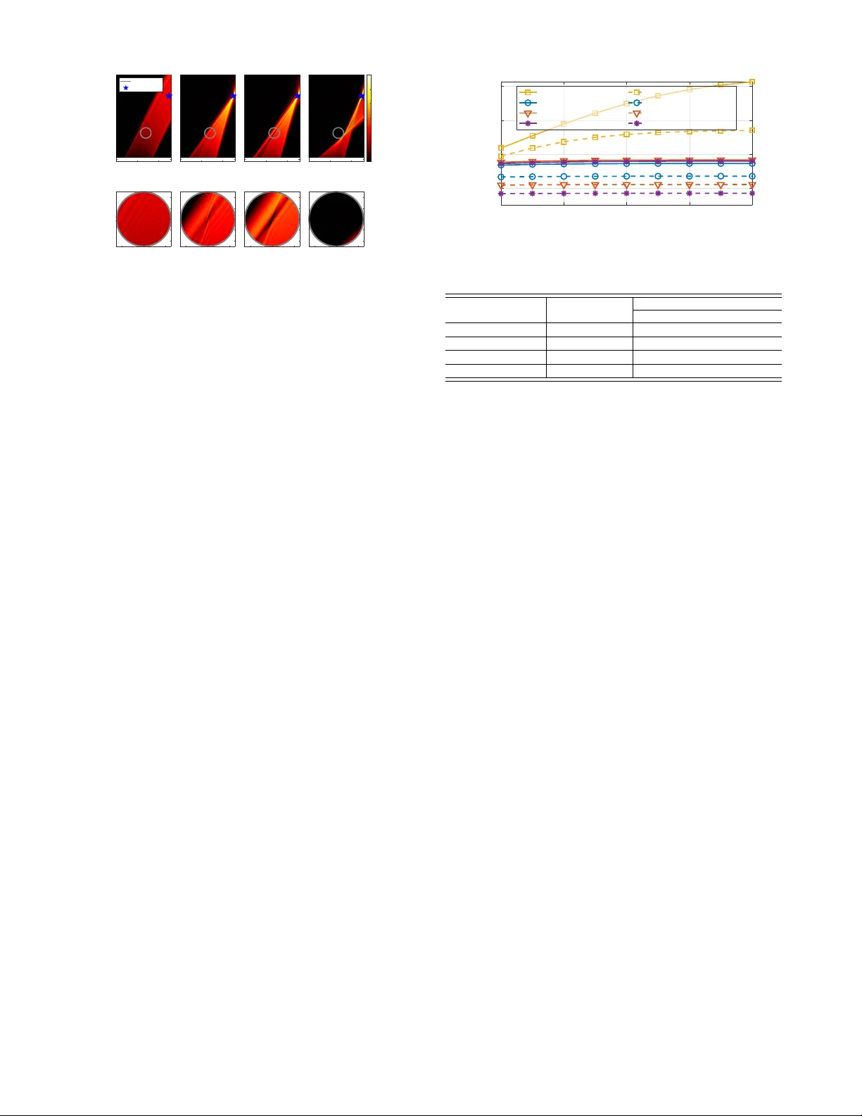
1 Rob ust and Secure Near -Field Communication via Curv ed Caustic Beams Shicong Liu, Graduate Student Member , IEEE , Xianghao Y u, Senior Member , IEEE , and Robert Schober , F ellow , IEEE Abstract —Near -field beamfocusing with extremely large aper- ture arrays can effectively enhance physical layer security . Nevertheless, ev en small estimation errors of the eavesdr opper’ s location may cause a pronounced focal shift, resulting in a se vere degradation of the secrecy rate. In this letter , we propose a physics-inf ormed rob ust beamforming strategy that leverages the electromagnetic (EM) caustic effect for near-field physical layer security provisioning, which can be implemented via phase shifts only . Specifically , we partition the transmit array into caustic and focusing subarrays to simultaneously bypass the potential eav esdropping r egion and illuminate the legitimate user , thereby significantly impr oving the robustness against the localization error of eavesdr oppers. Moreover , by leveraging the connection between the phase gradient and the EM wav e departing angle, we derive the corresponding piece-wise closed-f orm array phase profile for the subarrays. Simulation results demonstrate that the proposed scheme achieves up to an 80% reduction of the worst-case ea vesdropping rate for a localization err or of 0.25 m, highlighting its superiority f or providing robust and secure communication. Index T erms —Caustic, near field, robust design, secrecy rate, secure communication. I . I N T R O D U C T I O N For sixth-generation (6G) mobile communication systems, extremely large-scale MIMO (XL-MIMO) is expected to become a piv otal technology for achie ving unprecedented spectral ef ficiency and spatial resolution. With the growth of the number of elements in XL-MIMO, the associated increasing aperture significantly e xtends the Rayleigh distance, encompassing more users within the near-field re gion. The spherical wav efront in near -field electromagnetic (EM) wa ve propagation f acilitates beamfocusing [1], which concentrates energy at specific locations, allowing wireless systems to mitigate interference and achieve high data rates [2], [3]. Despite the promising potential of beamfocusing, existing research on near -field secure communication still suf fers from sev eral notable limitations. First, most studies ha ve assumed perfect channel state information (CSI) of the eav esdropper to be av ailable at the transmitter [2], which can be ov erly optimistic in practical passi ve wiretapping scenarios. Second, robust near-field designs often suffer from prohibitiv e com- putational complexity due to the use of iterativ e optimization procedures [4], which hinders their practical application in XL- MIMO systems. Furthermore, the CSI uncertainty in the near field is predominantly dictated by localization errors, which Shicong Liu and Xianghao Y u are with the Department of Electri- cal Engineering, City University of Hong Kong, Hong Kong (email: sc.liu@my .cityu.edu.hk, alex.yu@cityu.edu.hk). Robert Schober is with the Institute for Digital Communications, F A U, 91058 Erlangen, German y (email: robert.schober@fau.de). makes conv entional far -field robust optimization techniques, e.g., S-procedure, tailored to tackle norm-bounded CSI ac- quisition errors inapplicable [5]. Although the authors of [6] mitigate CSI uncertainty by injecting artificial noise into the null space of the legitimate channel, such a scheme still relies heavily on the degrees of freedom of the channel, and may suffer from user CSI mismatch. Third, the numerous existing robust design approaches still exhibit residual information leakage to eavesdroppers, potentially compromising secure links if the eavesdropper possesses strong detection capabili- ties. Therefore, de veloping low-complexity , robust, and nearly absolute secure beamforming strategies for near-field physical layer security remains a critical open challenge. T o fill this gap, we propose a nov el physics-informed robust and secure communication scheme in the near field by manipulating the en velope of a family of departing EM wav es, which is known as the EM caustics. In this work, we design the curv ed caustic beam trajectory synthesized by a hardware- efficient passiv e metasurface to steer the radiated energy to bypass a circular region defined by the localization error of the eav esdropper . In this way , information leakage to the designated region is suppressed. T o enhance energy efficienc y , we introduce a piece-wise trajectory design by partitioning the transmit array into focusing and caustic subarrays. Specifically , array elements with direct paths to the legitimate user that do not intersect the eavesdropping re gion form a focusing subarray , while the remaining array elements are assigned to a caustic subarray . Then, for the caustic subarray , the departing rays are designed to bypass the eavesdropping region, while for the focusing subarray , all departing rays are focused on the legitimate user . This approach combines the high ener gy efficienc y of beamfocusing with the security provisioning enabled by EM caustics. W e finally derive a closed-form phase profile to synthesize the desired curved caustic trajectory , which significantly reduces the computational ov erhead. I I . P R O B L E M S TA T E M E N T A. System Model Consider a near-field secure communication scenario as illustrated in Fig. 1(a), where a base station (BS) serves a single-antenna legitimate user equipment (UE), and an eav esdropper is wiretapping in the near-field re gion of the BS array . The BS is equipped with an M -element passi ve metasurface [7] deployed along the x -axis, with the m -th array element located at r ( m ) BS = ( x ( m ) BS , 0) , and the position of the UE is giv en by r UE = ( x UE , y UE ) . EM wav es radiated from 2 ? ? ? ? Ca u s t i c Tr a j e c t o r y Ta n g e n t Li n e Fig. 1. (a) Illustration of near -field secure communication and (b) table with notations. the radio frequency (RF) feed port illuminate the metasurface 1 and experience phase modulation when passing through the metasurface. W e adopt the spherical wa ve model [3] to characterize the near-field wireless channel as h ( r T , r R ) = e ȷκ ∥ r T − r R ∥ ∥ r T − r R ∥ , (1) where r T and r R are the coordinates of the transcei vers, respectiv ely . In addition, κ = 2 π /λ is the wavenumber with λ being the carrier wavelength, and ȷ is the imaginary unit such that ȷ 2 = − 1 . Therefore, the le gitimate channel vector h ∈ C M × 1 is giv en by h = h h r (1) BS , r UE , · · · , h r ( M ) BS , r UE i T . (2) It can be observed from (1) that near-field channel estimation is in principle a localization problem. In this w ork, we assume the av ailability of perfect location information { r ( m ) BS } M m =1 (and therefore the CSI h ) for the BS-UE link via effecti ve near- field localization methods [9]. In contrast, as eav esdroppers typically try to hide their existence from the BS, they are not expected to cooperate with the BS for localization. Hence, the location of the eavesdropper is modeled as r E = ˆ r E + ∆ r , where ˆ r E = ( x E , y E ) is the estimate of the ea vesdropper’ s location av ailable at the BS while the localization error is modeled by the term ∆ r . Consequently , the m -th element of the eavesdropping channel vector h E ∈ C M × 1 is modeled as [10] h r ( m ) BS , r E = h r ( m ) BS , ˆ r E + ∆ r , ∆ r ∈ Ω ε , Ω ε ≜ { r = ( x, y ) | ∥ r ∥ ≤ ε } , (3) where Ω ε contains all possible localization errors for the eav esdropper with their norms bounded by ε . Hence, the area depicted by Ω ε is a circle centered at ˆ r E with radius ε . B. Pr oblem F ormulation In this work, to av oid the high cost and hardware complex- ity associated with hundreds of phase shifters, we consider employing a passive metasurface to facilitate analog beam- forming. Let f = [ f 1 , · · · , f M ] T be the phase shift v ector of the metasurface at the BS, i.e., | f i | = 1 , ∀ 1 ≤ i ≤ M , and the 1 The channel between the RF feed and the m -th metasurface element can be characterized by a model similar to (1) based on their spatial separations [7, Eq. (6)] [8, Eq. (1)]. As this channel can be calibrated and compensated by the metasurface, further details are thereby omitted for brevity . achiev able rates R UE for the legitimate UE and R E for the eav esdropper are respectively given by R UE = log 2 1 + P T | h H f | 2 σ 2 n , R E = log 2 1 + P T | h H E f | 2 σ 2 n , where P T denotes the transmit po wer , and σ 2 n is the noise power at the receiv er . The secrecy rate R S between the BS and the legitimate UE is then e xpressed as R S = max (0 , R UE − R E ) . (4) Therefore, our design objecti ve is to maximize the worst- case secrecy rate in the potential eav esdropping region by designing the analog beamformer f without precise position information about the eav esdropper , which leads to the fol- lowing optimization problem max f min ∆ r ∈ Ω ε R S s . t . | f [ m ] | = 1 / √ M , ∀ 1 ≤ m ≤ M . (5) I I I . P R O P O S E D B E A M T R A J E C T O RY D E S I G N Instead of directly solving the robust and secure commu- nication problem (5) via relaxation and iterati ve numerical optimization, in this section, we propose a physics-informed method that le verages the geometric information characterized by Ω ε and curved caustic beam trajectories. Specifically , we dev elop a novel caustic beamforming scheme by partitioning the transmit array into caustic and focusing subarrays, where the caustic subarray suppresses the eavesdropping rate R E , while the focusing subarray enhances the legitimate rate R UE to jointly improve the worst-case secrecy rate in (5). A. Phase Gradients W e first present ho w the angles of departure (AoDs) of the caustic beam are manipulated by the phase gradient. T o facilitate a tractable deri vation, we assume continuous phase variation on the BS array , which will be discretized in the subsequent numerical simulations for performance ev aluation. W ithout loss of generality , we consider a monochromatic EM wa ve U ( x, y ) with wav elength λ in the xO y plane satisfy- ing the Helmholtz equation in a homogeneous and isotropic medium as ∇ 2 + κ 2 U ( x, y ) = 0 , (6) where ∇ 2 is the Laplace operator . Let the trial solution be U ( x, y ) = A ( x, y ) e ȷκD ( x,y ) , (7) where A ( x, y ) and D ( x, y ) are arbitrary real amplitude- and distance-related functions, respectiv ely . Substituting (7) into (6), we have ∇ 2 A + 2 ȷκ ∇ A · ∇ D + ȷκA ∇ 2 D − Aκ 2 |∇ D | 2 + κ 2 A = 0 , (8) where operator · denotes the inner product between vectors, and we omit the dependence on v ariables x and y for bre vity . Then, dividing (8) by κ 2 , we further have ∇ 2 A κ 2 + 2 ȷ ∇ A · ∇ D + ȷA ∇ 2 D κ + A 1 − |∇ D | 2 = 0 . (9) 3 Since wav enumber κ is typically large in wireless commu- nications, the impact of ∇ 2 A becomes insignificant in (9) due to the scaling with 1 /κ 2 . Besides, for a slow-v arying amplitude function A , the Laplacian ∇ 2 A is also generally small. Therefore, we can safely ignore this term and obtain a surrogate equation of (9) as ȷ κ 2 ∇ A · ∇ D + A ∇ 2 D + A 1 − |∇ D | 2 = 0 , (10) where the real and imaginary parts equal zero simultaneously , yielding ∥∇ D ( x, y ) ∥ = ∂ D ( x, y ) ∂ x , ∂ D ( x, y ) ∂ y = 1 (11) and 2 ∇ A ( x, y ) · ∇ D ( x, y ) + A ( x, y ) ∇ 2 D ( x, y ) = 0 . (12) For an EM wa ve U ( x, y ) , the lev el surface of the distance term D ( x, y ) is known as the wavefront, and the gradient ∇ D ( x, y ) is always perpendicular to the wav efront, which indicates the propagation direction. Since the magnitude of this gradient is equal to a constant according to (11), it follows that, if we can design and control the gradient components on the transmitting interface (e.g., the x -component on the y = 0 surface), we can then control the propagation direction of the EM wa ve. In other words, gi ven a desired AoD θ , see Fig. 2(a), one straightforward design of the phase profile of U ( x, y ) in (7), i.e., ϕ ( x, y ) = κD ( x, y ) , is given by ∂ ϕ ( x, y ) ∂ x y =0 = κ x = κ cos θ . (13) In this case, according to (11), the y -component of the phase gradient has to be [ ∂ ϕ ( x, y ) /∂ y ] y =0 = κ y = κ sin θ . Con- sequently , the departing beam propagates along the direction κ = ( κ x , κ y ) = ( κ cos θ , κ sin θ ) . Remark 1. Given specific boundary conditions at an inter- face, i.e., y = 0 , the solution in (13) is referr ed to as the generalized Snell’ s law [11]. Such a characteristic can also guide the design of beam steering and focusing by solving (13) with specific variations of the AoD θ . F or instance, the con ventional beam steering scheme along a fixed AoD θ , as shown in F ig. 2(a), can be re garded as the solution to (13) as ϕ Steering ( x ) = κ cos θ · x + C with C being an arbitrary constant. In this case, the phase profile is a linear function of x as shown in F ig. 2(d). Similarly , to focus all the transmit energy on a UE located at r UE = ( x UE , y UE ) , the AoD θ has to vary with x as cos θ = ( x UE − x ) / q ( x UE − x ) 2 + y 2 UE , (14) as shown in Fig . 2(b). The corr esponding focusing phase pr ofile is then calculated by substituting (14) into (13) as ϕ F o c ( x ) = Z κ cos θ d x = − κ ∥ r UE − ( x, 0) ∥ + C, (15) which aligns with con ventional beamfocusing [1], as illus- trated in F ig. 2(e). Fig. 2. Illustration of (a) steering beam, (b) focusing beam, and (c) caustic beam, as well as the corresponding phase profiles (d), (e), and (f). B. Caustic T rajectory Design Based on the described EM propagation characteristics, we can not only achie ve beam steering and focusing, but also tailor the curved caustic beams. A caustic is the env elope of a family of departing EM waves, stretching a focal point into a continuous trajectory . By elongating the focal point, the curved trajectory is able to bypass the undesired eav esdropping region Ω ε to support nearly absolute secure communication. In particular, we choose a spatial trajectory T that detours around the area Ω ε , and enforce that all beams radiated by the array are tangents to this trajectory , as sho wn in Fig. 2(c). In this way , the departing rays form an en velope that coincides with the prescribed trajectory , ensuring no departing EM wa ves pass through the area Ω ε . For instance, consider a curved spatial trajectory T ≜ { ( x, y ) | y = f ( x ) } ⊂ R 2 and an arbitrary point ( ξ , f ( ξ )) on it. Then, the tangent line at ( ξ , f ( ξ )) intersects the array at ( x ξ , 0) , where the x -intercept is gi ven by x ξ = ξ − f ( ξ ) f ′ ( ξ ) , x ∈ − L 2 , L 2 , (16) and L = ( M − 1) d is the aperture of the BS array , with d being the element spacing. Since the slope of the tangent line is given by the first order deriv ati ve f ′ ( ξ ) = tan θ , (13) then yields ∂ ϕ ( x ) ∂ x x = x ξ = κ cos θ = κ q 1 + ( f ′ ( ξ )) 2 . (17) The desired phase profile can then be obtained by solving (17). It is also w orth noting that, for trajectories characterized by basic elementary functions, the phase profile solutions corre- sponding to (17) are well established [12]. For e xample, the solution to (17) with the quadratic trajectory f ( x ) = ( x/a ) 2 shown in Fig. 2(f) is giv en by ϕ Quad ( x ) = κa 2 4 asinh 4 x a 2 . (18) In addition, when f is a parabolic function with acceleration parallel to the array axis, the beam synthesized by (17) reduces to the well-known Airy beam [13]. C. Pr oposed Secur e Beam T rajectory In this subsection, we propose a practical and generally applicable piece-wise caustic trajectory design, which im- prov es the energy ef ficiency by inte grating caustic shaping 4 ? Caus tic Traje ctory Tangent Line ? ? ? Ca u s t i c Tr a j e c t o r y Ta n g e n t Li n e Fig. 3. The proposed piece-wise trajectory design. with beamfocusing in the near field. The corresponding phase profile ϕ ( x ) is derived in closed form. Note that the deriv ations in this subsection rely on the spatial geometry shown in Fig. 3, while they can be readily generalized to scenarios with different geometric configurations of UE and eav esdroppers. First, according to the av ailability of direct line-of-sight (LoS) paths between BS array and the UE 2 , we partition the BS array re gion A = { x | − L/ 2 ≤ x ≤ L/ 2 } into a caustic subarray A C (without LoS paths) and a focusing subarray A F (with LoS paths), as illustrated in Fig. 3. The caustic subarray shapes its departing rays to bypass the eav esdropping region Ω ε , while the focusing subarray concentrates departing rays on the UE. Then, we can draw two tangent lines from the far end of the BS array T = ( − L/ 2 , 0) and the UE R = r UE to the circular region Ω ε , and select the two tangent segments T P and QR that lie closer to the focusing subarray . The corresponding tangent points P and Q then define the minor arc d P Q on the circle. Finally , a piece-wise caustic trajectory is constructed by T = T P ∪ d P Q ∪ QR, (19) as depicted in Fig. 3. In the following, according to the constructed trajectory T , we deri ve the phase profiles for the caustic and focusing subarrays, respecti vely . 1) Caustic Subarray: The tangent line with slope angle θ satisfies y = tan θ ( x − x t ) + y t , (20) where ( x t , y t ) on the boundary circle of Ω ε is defined by x t = x E + ε sin θ , y t = y E − ε cos θ . (21) Substituting (21) into (20), we have the x -intercept on the BS array as x θ = − y E − ε cos θ tan θ + x E + ε sin θ . (22) Since θ in (22) cannot be represented by a function of x in a simple form, directly solving ϕ ( x ) can be difficult. Hence, we consider solving ϕ ( θ ) first. According to (22), we hav e ∂ x θ ∂ θ = y E − ε cos θ sin 2 θ . (23) 2 In this letter , we focus on the single-user case to rev eal the underlying physical mechanism and obtain a more tractable closed-form phase profile. Howe ver , the proposed scheme can be extended to scenarios with multiple users/eav esdroppers by partitioning the entire BS array into multiple caustic subarrays to bypass multiple potential ea vesdropping regions and multiple focusing subarrays for user-specific secure beam design. Substituting (23) into (17), we hav e ∂ ϕ ( θ ) ∂ θ = ∂ ϕ ( θ ) ∂ x θ ∂ x θ ∂ θ = y E − ε cos θ sin 2 θ · κ cos θ , (24) which further yields ϕ ( θ ) = κ εθ + ε tan θ − y E sin θ , θ st ≤ θ ≤ θ ed , (25) with θ st and θ ed being the slope angles of the tangent line segments T P and QR , respectiv ely , as marked in Fig. 3. The constant bias of the integral is omitted for bre vity . According to the relationship between x and θ in (22), the closed-form expression for ϕ ( x ) is then giv en by ϕ ( x ) = κ 2 ε atan x − x E + S ( x ) ε + y E − S ( x ) , (26) where S ( x ) = q ( x − x E ) 2 + y 2 E − ε 2 . (27) 2) F ocusing Subarray: Since the focusing subarray has direct LoS paths to the UE, we directly concentrate all the transmit energy on the UE to boost the legitimate rate R UE . The phase profile for the focusing subarray is given by (15). In summary , the overall phase profile of the proposed trajectory (19) is given by ϕ ( x ) = ( (26) , x ∈ A C − κ p ( x UE − x ) 2 + y 2 UE + C , x ∈ A F , (28) where C is a constant to ensure the continuity of ϕ ( x ) . I V . M A I N R E S U LT S A. Simulation Setup In the simulation, the carrier frequency is set as f c = 28 GHz. The BS array is equipped with M = 256 array elements with half-wa velength spacing d = λ/ 2 . The transmit power of the BS is set as P T = 20 dBm, and the noise power at the receiv er is σ 2 n = − 50 dBm. The continuous phase solution in (28) is uniformly sampled and applied to the discrete metasurface. The following benchmarks are adopted to show the effecti veness of the proposed method. • Optimal Secure Focusing [14]: Assuming perfect CSI, the beamforming v ector is chosen as the dominant generalized eigen vector of the matrix pencil ( I M + P T σ 2 n hh H , I M + P T σ 2 n h E h H E ) , where I M denotes the identity matrix of order M . • Norm-Bounded Design [5]: The worst-case secrecy rate in the eav esdropping region Ω ε is maximized by the S- procedure via relaxation of the distance constraint to a channel norm error . • ADMM [4]: Problem (5) is relaxed and solved iterativ ely by a Dinkelbach approach. • Pr oposed Caustic Beam : The piece-wise phase profile is designed according to (28). 5 -1 0 1 x (m) 0 1 2 3 4 y (m) (a) Steering + " Boundary UE -1 0 1 x (m) 0 1 2 3 4 (b) F o cusing -1 0 1 x (m) 0 1 2 3 4 (c) Norm-Bounded -1 0 1 x (m) 0 1 2 3 4 (d) Proposed Caustic -30 -25 -20 -15 -10 -5 0 Normalized Strength (dB) (e) -0.2 0 0.2 x (m) -0.2 -0.1 0 0.1 0.2 y (m) (f ) -0.2 0 0.2 -0.2 -0.1 0 0.1 0.2 (g) -0.2 0 0.2 -0.2 -0.1 0 0.1 0.2 (h) -0.2 0 0.2 -0.2 -0.1 0 0.1 0.2 Fig. 4. The visualization of spatial beams of different phase profiles, with corresponding radiation details in the region Ω ε zoomed in. B. Caustic Beam V isualization T o provide an intuitiv e and clear illustration, we first visualize the resulting spatial beams 3 . The circular eaves- dropping region Ω ε is centered at ˆ r E = (0 . 4 , 1 . 25) m with radius ε = 0 . 25 m, and the UE is located at (1 . 5 , 3) m. Fig. 4 depicts the normalized radiation strength achie ved by different phase profiles, where the eavesdropping region Ω ε is zoomed in for a better vie w . The beam steering scheme in Fig. 4(a) radiates energy rather uniformly onto the UE direction θ = arctan( y UE /x UE ) , causing high leakage across the entire region Ω ε . In addition, the baseline schemes in Figs. 4(b) and (c) can only suppress the leakage in a very limited region within Ω ε , as depicted in Figs. 4(f) and 4(g). In contrast, the proposed method shown in Fig. 4(d) suc- cessfully steers the energy to bypass the eavesdropping region, which guarantees nearly absolute secure communication. Note that residual leakage still persists at the edge of the eav esdrop- ping region, as shown in Fig. 4(h), which is attrib uted to the omission of the term ∇ 2 A/κ 2 in (9) for a tractable analysis. This indicates that underestimating the radius ε may degrade the worst-case secrecy rate performance by introducing more residual leakage. T o avoid this, we can deliberately increase the radius ε of the ea vesdropping region by a small margin to ensure absolutely secure communication. It is also noteworthy that the schemes in Figs. 4(b) and 4(c), which employ non-unit-modulus beamforming weights, cannot be realized using phase shifts only . Despite this relaxation, they fail to match the performance of our proposed method, primarily because we exploit physics-informed EM properties as domain knowledge to bypass the eavesdropping region. C. Secr ecy Rate W e further in vestigate the secrecy rate performance with varying transmit power P T ∈ [10 , 30] dBm. As shown in Fig. 5, the proposed scheme consistently achie ves superior secrecy rate performance in both mean and worst-case secrec y rate scenarios, indicating superior robustness over other com- paring schemes. This is because of the significant suppression of energy leakage into the potential eav esdropping region, which leads to a substantial decrease of R E in (4). In the high SNR near-field region, additional transmit power leads 3 W e consider a pessimistic case with the eavesdropper located close to the BS, which can be a typical scenario in indoor en vironments [13] 10 15 20 25 30 T ransmit Pow er P T (dBm) 2 4 6 8 Secrecy Rate (bps/Hz) (Mean) Proposed (Mean) Opt. F o cusing (Mean) Norm-Bounded (Mean) ADMM (W orst) Prop osed (W orst) Opt. F ocusing (W orst) Norm-Bounded (W orst) ADMM Fig. 5. Mean and worst-case rate performance versus transmit power P T . T ABLE I C O M P U TA T I O NA L C O M P L E X I T Y A N D M E A N E X E C U T I O N T I M E Methods Computational Complexity Execution Time (s) M = 64 M = 256 Opt. Focusing [14] O (3 M 3 + M 2 ) 2 . 91 × 10 − 3 1 . 01 × 10 − 1 Norm-Bounded [5] ∼ O ( M 4 . 5 ) 1 . 81 27 . 4 ADMM [4] ∼ O ( M 3 ) 3 . 05 × 10 − 2 1 . 04 × 10 − 1 Proposed N/A 7 . 61 × 10 − 4 9 . 64 × 10 − 4 to an increase in both legitimate and eavesdropping rates, and therefore, the secrec y rate tends to remain constant. In contrast, the proposed curved caustic beams can always bypass the potential ea vesdropping re gion. Hence, more transmit power illuminating the UE leads to a rapid increase in secrec y rate. D. Computational Complexity W e finally e valuate the computational complexity of the proposed scheme. The computational complexity and the mean ex ecution time are shown in T able I, where the complexity is ev aluated by the number of multiplications, and the time is averaged over 1 , 000 realizations. The proposed scheme shows a significantly shorter execution time than the baseline methods. Moreo ver , the e xecution time of the proposed scheme increases only mar ginally by about 25% as M increases by four times, which sho ws its scalability in XL-MIMO systems. V . C O N C L U S I O N In this letter , we exploited EM wav e caustics to f acilitate secure near-field communication in the presence of ea vesdrop- per localization errors. W e first designed a curved caustic trajectory that bypasses the eavesdropping region, and then deriv ed the corresponding phase profile to generate the desired caustic beam. Numerical results demonstrated substantial gains in both the mean and worst-case secrecy rate performance, highlighting the potential of the proposed caustic scheme for providing rob ust physical layer security . In practice, hardware imperfections, such as phase quantization and phase noise, may cause distortion of the synthesized trajectory . Thus, additional studies are needed to further e valuate and improve practical deployability . R E F E R E N C E S [1] H. Zhang, N. Shlezinger , F . Guidi, D. Dardari, M. F . Imani, and Y . C. Eldar , “Beam focusing for near-field multiuser MIMO communications, ” IEEE T rans. W ireless Commun. , vol. 21, no. 9, pp. 7476–7490, Sept. 2022. [2] Y . Zhang, H. Zhang, S. Xiao, W . T ang, and Y . C. Eldar, “Near-field wideband secure communications: An analog beamfocusing approach, ” IEEE T rans. Signal Process. , vol. 72, pp. 2173–2187, Apr . 2024. 6 [3] J. An, C. Y uen, L. Dai, M. Di Renzo, M. Debbah, and L. Hanzo, “Near- field communications: Research advances, potential, and challenges, ” IEEE W ireless Commun. , vol. 31, no. 3, pp. 100–107, Jun. 2024. [4] Q. Li, C. Li, and J. Lin, “Constant modulus secure beamforming for multicast massive MIMO wiretap channels, ” IEEE T rans. Inf. F orensics Security , vol. 15, pp. 264–275, May 2020. [5] Z. Chen, F . W ang, G. Han, X. W ang, and V . K. N. Lau, “Robust beamforming design for secure near-field ISAC systems, ” IEEE W ireless Commun. Lett. , v ol. 14, no. 10, pp. 3089–3093, Oct. 2025. [6] Z. T eng, J. An, C. Masouros, H. Li, L. Gan, and D. W ing Kwan Ng, “Dynamic precoding for near-field secure communications: Implementa- tion and performance analysis, ” IEEE Internet Things J. , vol. 12, no. 15, pp. 29 427–29 442, Aug. 2025. [7] V . Jamali, A. M. T ulino, G. Fischer , R. R. M ¨ uller , and R. Schober, “Intelligent surface-aided transmitter architectures for millimeter-wa ve ultra massiv e MIMO systems, ” IEEE Open J. Commun. Soc. , vol. 2, pp. 144–167, 2021. [8] K. K. Tiwari and G. Caire, “RIS-based steerable beamforming antenna with near-field eigenmode feeder , ” in IEEE Int. Conf. Commun. (ICC) , 2023, pp. 1293–1299. [9] S. Liu, X. Y u, Z. Gao, J. Xu, D. W . K. Ng, and S. Cui, “Sensing- enhanced channel estimation for near-field XL-MIMO systems, ” IEEE J. Sel. Ar eas Commun. , v ol. 43, no. 3, pp. 628–643, Mar . 2025. [10] X. Y u, D. Xu, Y . Sun, D. W . K. Ng, and R. Schober, “Robust and secure wireless communications via intelligent reflecting surfaces, ” IEEE J. Sel. Ar eas Commun. , vol. 38, no. 11, pp. 2637–2652, Nov . 2020. [11] N. Y u et al. , “Light propagation with phase discontinuities: Generalized laws of reflection and refraction, ” Science , vol. 334, no. 6054, pp. 333– 337, Sept. 2011. [12] L. Froehly et al. , “ Arbitrary accelerating micron-scale caustic beams in two and three dimensions, ” Opt. Express , v ol. 19, no. 17, pp. 16 455– 16 465, Aug. 2011. [13] H. Guerboukha, B. Zhao, Z. Fang, E. Knightly , and D. M. Mittleman, “Curving THz wireless data links around obstacles, ” Comms. Eng. , vol. 3, no. 1, p. 58, Mar . 2024. [14] A. Khisti and G. W . W ornell, “Secure transmission with multiple antennas I: The MISOME wiretap channel, ” IEEE T rans. Inf. Theory , vol. 56, no. 7, pp. 3088–3104, July 2010.
Original Paper
Loading high-quality paper...
Comments & Academic Discussion
Loading comments...
Leave a Comment