6D Movable Antenna for Internet of Vehicles: CSI-Free Dynamic Antenna Configuration
Deploying six-dimensional movable antenna (6DMA) systems in Internet-of-Vehicles (IoV) scenarios can greatly enhance spectral efficiency. However, the high mobility of vehicles causes rapid spatio-temporal channel variations, posing a significant cha…
Authors: Maoxin Ji, Qiong Wu, Pingyi Fan
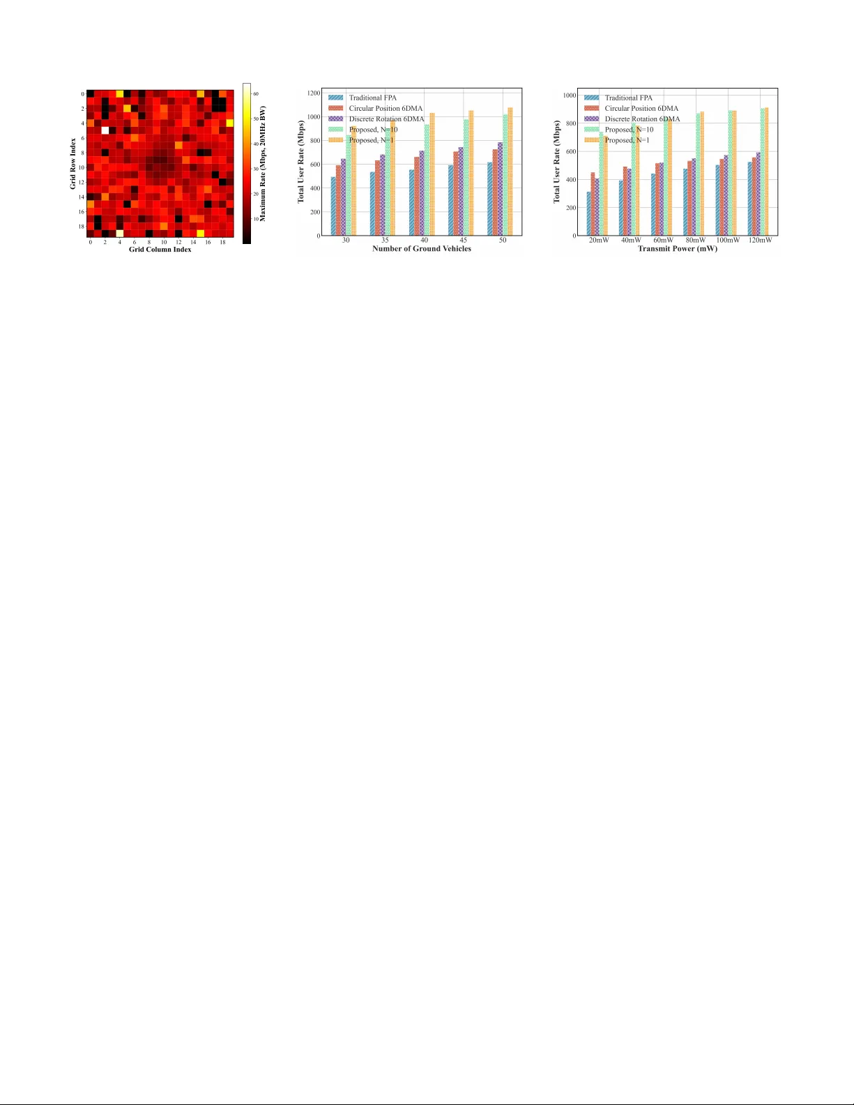
6D Mo v able Antenna for Internet of V ehicles: CSI-Free Dynamic Antenna Configuration Maoxin Ji 1 , 2 , Qiong W u 1 , 2 , ∗ , Pingyi Fan 3 , K ezhi W ang 4 , W en Chen 5 and Khaled B. Letaief 6 1 School of Internet of Things Engineering, Jiangnan Univ ersity , W uxi 214122, China 2 School of Information Engineering, Jiangxi Provincial K ey Laboratory of Adv anced Signal Processing and Intelligent Communications, Nanchang Univ ersity , Nanchang 330031,China 3 Department of Electronic Engineering, State Ke y laboratory of Space Network and Communications, Beijing National Research Center for Information Science and T echnology , Tsinghua University , Beijing 100084, China 4 Department of Computer Science, Brunel Univ ersity , London, Middlesex UB8 3PH, U.K 5 Department of Electronic Engineering, Shanghai Jiao T ong Uni versity , Shanghai 200240, China 6 Department of Electrical and Computer Engineering, the Hong K ong Univ ersity of Science and T echnology (HKUST), Hong K ong ∗ Corresponding author is Qiong W u. Email: maoxinji@stu.jiangnan.edu.cn, qiongwu@jiangnan.edu.cn, fpy@tsinghua.edu.cn, K ezhi.W ang@brunel.ac.uk, wenchen@sjtu.edu.cn, eekhaled@ust.hk Abstract —Deploying six-dimensional movable antenna (6DMA) systems in Internet-of-V ehicles (IoV) scenarios can greatly enhance spectral efficiency . Howev er , the high mobility of vehicles causes rapid spatio-temporal channel variations, posing a significant challenge to real-time 6DMA optimization. In this work, we pioneer the application of 6DMA in IoV and propose a low-complexity , instantaneous channel state information (CSI)-free dynamic configuration method. By integrating vehicle motion prediction with offline directional response priors, the proposed appr oach optimizes antenna positions and orientations at each reconfiguration epoch to maximize the av erage sum rate over a future time window . Simulation r esults in a typical urban intersection scenario demonstrate that the proposed 6DMA scheme significantly outperforms con ventional fixed antenna arrays and simplified 6DMA baseline schemes in terms of total sum rate. Index T erms —6DMA, IoV , user distribution. I . I N T RO D U C T I O N The Internet of V ehicles (IoV) is experiencing rapidly growing communication demands, requiring ultra-low latency and ultra-high reliability [1]–[4]. Howe ver , the high mobility of vehicles introduces fast time-varying channel conditions, posing significant challenges to wireless network design [5]– [8]. T o accommodate the increasing demand, scaling up antenna deployments has become the mainstream trend. In IoV , multiple-input multiple-output (MIMO) [9] and even This work was supported in part by Jiangxi Province Science and T echnol- ogy De velopment Programme under Grant No. 20242BCC32016, in part by the National Natural Science Foundation of China under Grant No. 61701197, 62531015, and U25A20399, in part by the Basic Research Program of Jiangsu under Grant BK20252084, in part by the National Key Research and Dev elopment Program of China under Grant No. 2021YF A1000500(4), in part by the Shanghai Ke wei under Grant 24DP1500500, in part by the Hong Kong Research Grant Council under the Area of Excellence (AoE) Scheme Grant No. AoE/E-601/22-R and in part by the 111 Project under Grant No. B23008. massiv e MIMO [10], [11] have been successively proposed. Howe v er , the continual gro wth in antenna scale leads to sub- stantial hardware costs and markedly increased computational complexity in signal processing. Consequently , improving antenna utilization under a limited antenna b udget is of critical importance. Recently , Shao et al. proposed a novel six-dimensional mov able antenna (6DMA) technology [12], which deploys antenna surfaces at dif ferent 3D positions with 3D rotations, providing highly flexible spatial distribution and achieving significant performance gains with a limited number of an- tennas. Moreov er , 6DMA can adjust antenna positions by capturing slowly varying user distributions in space, resulting in a low adjustment frequency and offering clear advantages ov er existing fluid antenna system (F AS) [13] and two- dimensional mov able antenna technologies [14]. Howe v er , this high deployment flexibility also introduces significant complexity in optimizing the positions and orienta- tions of the 6DMA system. On one hand, the lack of efficient channel state information (CSI) estimation hinders quantita- tiv e assessment during antenna placement optimization. On the other hand, the joint 3D positioning and 3D rotation create a high-dimensional action space, making it difficult to obtain the global optimum. T o address these challenges, reference [15] proposed a Monte Carlo-based method to esti- mate av erage channel capacity and an alternating optimization scheme to obtain suboptimal antenna positions. In [16], a discrete 6DMA system with a finite set of feasible positions and rotations was constructed using the Fibonacci-sphere method under practical constraints, and an online optimization approach based on measured rates was de veloped. Reference [17] introduced a fast CSI estimation method for 6DMA and a sequential optimization algorithm that first determines rotations and then selects positions. In [18], the directional sparsity of 6DMA systems was rev ealed, and the 6DMA po- sitions and rotations were optimized by le veraging statistical CSI to estimate channel power . In addition, reference [19] proposed a passiv e 6DMA scheme via an unmanned aerial vehicle (U A V)-mounted intelligent reflecting surface (IRS) to realize 3D position and orientation adjustments, along with an alternating optimization algorithm for the U A V’ s position and attitude. These studies adv anced 6DMA technology and verified its superiority over con v entional antenna strategies. Integrating 6DMA into IoV holds great promise, yet it entails significant technical challenges. On one hand, small- scale fading v aries rapidly in IoV communications, and when combined with the complex 6DMA layout, predict- ing instantaneous CSI becomes extremely difficult, which impedes quantitati ve optimization of 6DMA positions and rotations. On the other hand, due to high vehicular mobility , user distributions change quickly . Therefore, 6DMA may need to adjust antenna positions frequently to attain near- instantaneous optimality or adjust more slowly to pursue long-term, rob ust suboptimal performance. Moreo ver , existing 6DMA optimization algorithms either estimate user rates via Monte Carlo methods [15] or require extensi ve sampling ov er many antenna configurations [16], resulting in high complexity and limited efficiency for IoV scenarios. T o address these challenges, we formulate an optimization problem that maximizes the long-term sum rate in IoV en vironments. V ehicle locations are updated every time slot, while 6DMA positions are updated ev ery N slots. Based on predicted future vehicular distributions, antenna positions are adjusted to maximize the av erage sum rate over the next N slots, without computing instantaneous CSI 1 . Further- more, lev eraging the directional sparsity inherent to 6DMA antennas, we propose an online optimization scheme that exploits predicted side information and historical measured rate information to enable rapid allocation from historical knowledge. T o the best of our knowledge, this is the first work to apply 6DMA to IoV scenarios. I I . S Y S T E M M O D E L W e consider an urban cross-junction scenario as depicted in Fig. 1, where vehicles are uniformly distributed along two perpendicular roads. T ime is slotted with duration ∆ t , and vehicle positions are assumed quasi-static within each slot but updated at slot boundaries. At the beginning of every slot, the velocity of each vehicle is sampled from a truncated Gaussian distribution. Let K = { 1 , 2 , . . . , K } denote the set of vehicles. A single base station (BS) is located at the intersection center and serves all vehicles in the uplink. Each vehicle is equipped with a fixed-position antenna (FP A), while the BS employs a 6DMA system. 1 The source code has been released at: h ttp s:// git hu b. co m/ q io ng wu 86 / 6 D- Movab le- A nte nna- for- Inte rnet- of- Ve hicl es- CS I- F ree- D ynam ic- Anten na - Configuration. Fig. 1: System Model A. Discrete-P osition 6DMA Antenna System The 6DMA architecture consists of multiple antenna sur- faces, each capable of independent 3D translation and ro- tation, connected to a central processing unit (CPU) via telescopic mechanical links. Due to hardware constraints, both position and orientation are restricted to discrete sets. Specifically , let M and J denote the numbers of feasible discrete positions and rotations, respectively . The catalog of admissible 6D configurations is defined as P = { ( q i , r j ) | i = 1 , . . . , M ; j = 1 , . . . , J } , where q i = [ x i , y i , z i ] ⊤ ∈ R 3 is the center position of a surface and r j = [ α j , β j , γ j ] ⊤ represents the Euler angles (in radians) that rotate the surface from its zero-rotation reference pose. In this reference pose, the outward unit normal vector aligns with e x = [1 , 0 , 0] ⊤ . For a given rotation r j , the resulting outward normal n j is n j = cos β j cos γ j sin α j sin β j cos γ j − cos α j sin γ j cos α j sin β j cos γ j + sin α j sin γ j . (1) Consider a deployment that chooses U surfaces from the set P , where U ≤ M . T o compactly represent the deployment configuration, we define a binary matrix Z ∈ { 0 , 1 } M × J , where [ Z ] i,j = 1 if a surface is deployed at position i with rotation j , and 0 otherwise. The total number of deployed surfaces is enforced by P M i =1 P N j =1 [ Z ] i,j = U. The deployment should satisfy the following physical con- straints. First, mutual reflection/blockage av oidance requires that for any two distinct deployed surfaces at ( i, j ) and ( i ′ , j ′ ) (i.e., [ Z ] i,j = [ Z ] i ′ ,j ′ = 1 and ( i, j ) = ( i ′ , j ′ ) ), the surface at ( i, j ) should not face the one at ( i ′ , j ′ ) , which is enforced by n ⊤ j ( q i ′ − q i ) ≤ 0 . (2) Second, CPU blockage av oidance mandates that all deployed surfaces point aw ay from the CPU, i.e., n ⊤ j q i ≥ 0 , (3) for all ( i, j ) such that [ Z ] i,j = 1 . Third, minimum inter- surface spacing ensures that any two surfaces at distinct positions are separated by at least d min , i.e., ∥ q i − q i ′ ∥ 2 ≥ d min , (4) for all ( i, j ) , ( i ′ , j ′ ) with [ Z ] i,j = [ Z ] i ′ ,j ′ = 1 and i = i ′ . Finally , one surface per position is imposed by J X j =1 [ Z ] i,j ≤ 1 , ∀ i = 1 , . . . , M . (5) B. Channel Model W e consider the uplink transmission from K vehicles to the BS. Each 6DMA surface is equipped with Q FP A elements, yielding a total of U ∗ Q receive antennas. W e adopt a hybrid near –far field model [20]: propagation between different surfaces is in the far-field regime, while intra-surface element responses account for near-field spherical w av efronts. Let p k ∈ R 3 denote the position of vehicle k . The direction from vehicle k to surface at ( i, j ) is ˆ d k,i,j = p k − q i ∥ p k − q i ∥ . (6) T o characterize the local incident angles, we construct an orthonormal basis on the tangent plane of surface ( i, j ) . With e ref = [0 , 0 , 1] ⊤ , define u i,j = n j × e ref ∥ n j × e ref ∥ , v i,j = n j × u i,j , and the tangential projection ˆ d ∥ k,i,j = ˆ d k,i,j − ( n ⊤ j ˆ d k,i,j ) n j ∥ ˆ d k,i,j − ( n ⊤ j ˆ d k,i,j ) n j ∥ . The local elev ation and azimuth angles are then ˜ θ k,i,j = arccos( n ⊤ j ˆ d k,i,j ) , (7) ˜ ϕ k,i,j = atan2 ˆ d ∥⊤ k,i,j v i,j , ˆ d ∥⊤ k,i,j u i,j . (8) Follo wing the 3GPP radiation pattern model [21], the horizontal and vertical attenuation terms are A H = − min 12 ˜ ϕ k,i,j ϕ 3dB ! 2 , A m , A V = − min 12 ˜ θ k,i,j θ 3dB ! 2 , A m , (9) and the linear-scale element gain is G (lin) k,i,j = 10 G max − min( − ( A H + A V ) ,A m ) 10 , where ϕ 3dB and θ 3dB are the horizontal and vertical half-po wer beamwidths, respectiv ely , A m denotes the maximum sidelobe attenuation, and G max is the maximum antenna gain in the boresight direction. For each potential path ℓ between vehicle k and surface ( i, j ) , the path loss PL k,i,j,ℓ is determined by the 3GPP urban microcell (UMi) model [21] based on the geometric distance d k,i = ∥ p k − q i ∥ . The Line-of-Sight (LoS) probability is p LoS ( d k,i ) = min d 1 d k,i , 1 1 − e − d k,i /d 2 + e − d k,i /d 2 , (10) where d 1 = 18 , d 2 = 36 . For each path ℓ , a Monte Carlo trial is performed: W ith probability p LoS ( d k,i ) , the link is LoS and PL k,i,j,ℓ = 32 . 4 + 21 log 10 d k,i + 20 log 10 f c , (11) otherwise it is Non-Line-of-Sight (NLoS) and PL k,i,j,ℓ = 35 . 3 log 10 d k,i + 22 . 4 + 21 . 3 log 10 f c + χ ℓ , (12) where χ ℓ ∼ N (0 , σ 2 S F ) and σ S F = 7 . 82 dB. The corre- sponding linear large-scale power gain is defined as η (LS) k,i,j,ℓ = 10 − PL k,i,j,ℓ / 10 . Let the global coordinates of the m -th element on surface ( i, j ) be c i,j,m = q i + u m u i,j + v m v i,j , (13) with u m , v m ∈ {− s/ 2 , s/ 2 } for a square array of side length s . The near -field spherical-wav e phase from vehicle k to this element is ϕ k,i,j,m,ℓ = − 2 π λ ∥ p k − c i,j,m ∥ . (14) Assuming a small set of dominant paths ℓ ∈ D k,i,j , each with independent Rayleigh fading ξ k,i,j,ℓ ∼ C N (0 , 1) , the per-element channel coefficient is h k,i,j,m = X ℓ ∈D k,i,j q η (LS) k,i,j,ℓ · q G (lin) k,i,j,ℓ · e j ϕ k,i,j,m,ℓ · ξ k,i,j,ℓ , (15) where the near-field effect is explicitly captured by the element-dependent phase term e j ϕ k,i,j,m,ℓ , while the direc- tional radiation pattern and large-scale path loss are modeled via G (lin) k,i,j,ℓ and η (LS) k,i,j,ℓ , respectiv ely . Stacking across elements and surfaces, the channel vector for user k is h k = [ · · · , h ⊤ k,i,j , · · · ] ⊤ ∈ C B Q , where h k,i,j = [ h k,i,j, 1 , . . . , h k,i,j,Q ] ⊤ for each ( i, j ) with [ Z ] i,j = 1 , and the ov erall channel matrix is H = [ h 1 , . . . , h K ] ∈ C B Q × K . The computation of H ( t ) can be regarded as a mapping from the vehicle positions { p k ( t ) } K k =1 and the 6DMA configuration Z ( t ) , expressed as: H ( t ) = H { p k ( t ) } K k =1 , Z ( t ) . The matched-filter signal-to-interference-plus-noise ratio (SINR) [22]–[24] for user k is gi ven by Γ k H = P k ∥ h k ∥ 2 P j = k P j | h H k h j | 2 ∥ h j ∥ 2 + ε + σ 2 , (16) with a regularization constant ε > 0 , where σ 2 denotes the noise power at the receiv er . The achie vable rate is R k = B log 2 (1 + Γ k H ) , (17) and the sum rate is R sum = P K k =1 R k , where B denotes the system bandwidth. C. Pr oblem F ormulation Due to the high mobility of vehicles, user positions ev olve rapidly , resulting in fast-changing spatial distributions. While the 6DMA system can enhance performance by adapting its configuration to the user distribution, mechanical and computational constraints prohibit per-slot reconfiguration. W e discretize time into slots of duration ∆ t . The position of vehicle k at slot t , denoted p k ( t ) ∈ R 3 , follows the linear kinematic model p k ( t + 1) = p k ( t ) + v k ( t ) a k ( t ) ∆ t, (18) where v k ( t ) ≥ 0 is the instantaneous speed and a k ( t ) ∈ R 3 is the unit direction vector . T o balance adaptivity and practicality , we update Z once ev ery N slots. During the l -th optimization cycle, covering slots t ∈ { ( l − 1) N + 1 , . . . , l N } , the configuration remains fixed: Z ( t ) = Z l . Lev eraging the spatial-temporal regularity of vehicular traf- fic, we predict future positions using the instantaneous av er- age velocity ¯ v ( t ) = 1 K P K k =1 v k ( t ) , and recursiv ely compute ˆ p k ( t + 1) = ˆ p k ( t ) + a k ( t ) ¯ v ( t )∆ t , with ˆ p k (0) = p k (0) . The av erage total user rate over the next N time slots based on the predicted positions can be computed as follows. Let t l ≜ ( l − 1) N + 1 denote the starting time index of the l th period. Then, C avg ( Z l ) ≜ t l + N − 1 X t = t l K X k =1 B N log 2 1 + Γ k H . (19) The complete optimization problem can be formulated as follows: max Z l C avg ( Z l ) (20a) s.t. M X i =1 N X j =1 [ Z l ] i,j = U, (20b) N X j =1 [ Z l ] i,j ≤ 1 , ∀ i = 1 , . . . , M , (20c) n ⊤ j ( q i ′ − q i ) ≤ 0 , ∀ ( i, j ) , ( i ′ , j ′ ) , (20d) n ⊤ j q i ≥ 0 , ∀ ( i, j ) , (20e) ∥ q i − q i ′ ∥ 2 ≥ d min , ∀ ( i, j ) , ( i ′ , j ′ ) (20f) [ Z l ] i,j ∈ { 0 , 1 } , ∀ ( i, j ) , (20g) where constraint (20b) ensures exactly U surfaces are de- ployed. Constraint (20c) enforces that each discrete position hosts at most one surface. Constraints (20d)–(20f) encode the physical feasibility requirements: mutual reflection/blockage av oidance, CPU visibility , and minimum inter-surface spac- ing, respecti vely . Constraint (20g) imposes binary selection ov er the discrete configuration catalog Z l . This formulation enables proacti ve, low-comple xity 6DMA reconfiguration that exploits spatial-temporal predictability in vehicular traffic, while respecting hardware limitations and av oiding reliance on instantaneous channel state information. I I I . O P T I M I Z AT I O N M E T H O D In this section, we introduce a grid-based method for determining feasible locations and orientations. Furthermore, we exploit 6DMA sparsity in an online optimization fusing pre-test and historical rates. A. Discrete P osition and Orientation Construction T o address the lack of explicit neighborhood structure in random spherical discretization schemes (e.g., Fibonacci sampling) [25], [26], we employ a deterministic grid on a sphere of radius R around the BS. The sphere is divided into F equally spaced meridians, yielding the azimuth set Φ = n φ f = 2 π f F o F − 1 f =0 . T o satisfy the minimum inter -surface distance constraint d min , we first determine the first valid latitude circle near each pole. Let the chord length between adjacent points on this circle (along meridians) be at least d min . The corresponding circle radius should satisfy r first = d min 2 sin( π /F ) . The polar angle is then θ first = arccos( r first /r 0 ) , where r 0 denotes the radius of the sphere. The axial distance from the pole to this latitude circle is d pole = r 0 (1 − cos θ first ) . The av ailable axial length 2 r 0 − 2 d pole yields the maximum number of intermediate latitude circles: L = 2 r 0 − 2 d pole d min , (21) where ⌊·⌋ denotes the floor function. Including the two poles, the total number of discrete positions is M = F · L + 2 , where each non-polar position is represented in spherical coordinates as ( r 0 , θ g , φ f ) , where θ g denotes the polar angle of the g -th intermediate latitude circle. T o define orientation degrees of freedom, an 8- neighborhood structure is established for each non-polar position, comprising adjacent points along the same merid- ian (up/down), same latitude (left/right), and four diagonal neighbors. For any two adjacent neighbors q i 1 , q i 2 and the current position q i , the unit normal of the triangle they form is n ( m ) i = ( q i 1 − q i ) × ( q i 2 − q i ) ∥ ( q i 1 − q i ) × ( q i 2 − q i ) ∥ , m = 1 , . . . , 8 . (22) Additionally , the radial outward normal is included: n (0) i = q i ∥ q i ∥ , yielding J = 9 discrete orientations per position. The poles are handled via virtual neighbors to also maintain 9 orientations. The total number of feasible configurations is |P | = M × J . This construction inherently satisfies the minimum spacing constraint ∥ q i − q i ′ ∥ 2 ≥ d min and the CPU blockage av oidance condition n ⊤ j q i ≥ 0 . B. Offline Response Modeling The 6DMA system exhibits strong directional sparsity: a single surface provides significant gain only to users in a limited spatial region. T o quantify this, a one-time offline profiling is performed prior to deployment to establish a “spatial region–preferred configuration” prior mapping. The ground service area [0 , X ] × [0 , Y ] is partitioned into square grids of side length W , resulting in a total of N grid = X W · Y W grids, where ⌈·⌉ denotes the ceiling function. The center of grid ( g x , g y ) is c g x ,g y = ( g x − 1 2 ) W , ( g y − 1 2 ) W , z veh ⊤ , (23) where z veh denotes the typical vehicle height. W ithin each grid, S representati ve user positions { p ( s ) g } S s =1 are uniformly sampled. Using a single 6DMA surf ace (equipped with a 2 × 2 FP A array) as the radiation unit, the average theoretical rate of each feasible configuration ( q i , r j ) ∈ P for the grid is ev aluated as ¯ r g ( i, j ) = 1 S S X s =1 B log 2 1 + SINR p ( s ) g ; q i , r j , (24) where the SINR is giv en by (16). For each grid, the top- H configurations form the offline candidate set: C g = { ( q i , r j ) ∈ P | ¯ r g ( i, j ) ranks among the top H } . (25) This prior library captures the directional response charac- teristics under stable scattering and macroscopic geometry , providing a high-quality , compact candidate pool for online decision-making. C. Online Optimization Based on Historical Rates Since dynamic vehicle distributions cause deviations from offline assumptions, we introduce an online mechanism to refine priors using real-time rates. Let the l -th reconfiguration cycle span time slots T l , with 6DMA configuration Z l and vehicle positions { p k ( t ) } . The av erage rate for grid g in this cycle is ˆ R l g = 1 |K l g | · |T l | X k ∈K l g X t ∈T l R k ( t ) , (26) where K l g is the set of users mapped to grid g . The rate change ∆ R l g = ˆ R l g − ˆ R l − 1 g driv es prior updates. Each grid maintains a dynamic candidate set S g , where each configuration ( q i , r j ) is associated with a quality score q g ,i,j ∈ [0 , 1] and a usage count ν g ,i,j . The update rules are as follows. When configuration ( q i , r j ) is activ e in cycle l , its usage count is always incremented ( ν g ,i,j ← ν g ,i,j + 1 ), and its quality score q g ,i,j is adjusted based on the observed rate change ∆ R l g : if ∆ R l g > δ , then q g ,i,j is increased by η + ∆ R l g ; if ∆ R l g < − δ , it is decreased by η − | ∆ R l g | ; otherwise, it remains unchanged. The score is always projected onto the interval [0 , 1] , where η + > 0 and η − > 0 are step sizes that control the adaptation speed for positiv e and negativ e performance feedback, respecti vely , and δ > 0 is a sensitivity threshold that filters out negligible rate variations. New high- performing configurations are admitted with an initial score q 0 ∈ (0 , 1] , and the lowest-scoring entry is removed upon capacity ov erflow . At each reconfiguration instant, the candidate sets of all activ e grids (i.e., |K l g | > 0 ) are aggregated into a global candidate set U = S g S g . F or each candidate ( q i , r j ) ∈ U , a priority score is computed as π g ,i,j = q g ,i,j · ρ g · w rank · (1 + κ · ν g ,i,j ) , (27) where ρ g is the grid demand weight (e.g., the current number of users in grid g ), w rank is a rank-based weighting factor (e.g., w rank = H − rank + 1 with H denoting the maximum rank), and κ > 0 is an exploration bonus coefficient that promotes frequently used configurations. T ABLE I: V alues of parameters Parameter V alue Parameter V alue K 30/35/40/45/50 v 10 − 20 m/s U 16 Q 4(2 ∗ 2) B 20 M H z N 10 / 1 d min 10 cm R 0 . 5 m X ∗ Y 300 m ∗ 300 m W 15 m F 12 S 20 A greedy selection strategy picks configurations in de- scending order of π g ,i,j until U surf aces are allocated. A set of selected positions Q sel is maintained to ensure that no duplicate antenna positions are selected. D. Prediction-Enhanced P erformance Optimization T o improve long-term performance under low-frequenc y reconfiguration, a motion prediction mechanism is employed. At each reconfiguration instant, future v ehicle positions { ˆ p k ( t ) } N t =1 ov er the next N slots are predicted using a motion model. The cumulativ e demand density for grid g is then ˜ ρ g = N X t =1 K X k =1 1 ˆ p k ( t ) ∈ grid g . (28) Using ˜ ρ g as the demand weight ρ g in priority computation shifts the optimization objectiv e from instantaneous to time- av eraged performance over a prediction window , significantly enhancing robustness. Complexity Analysis: The proposed method ensures low latency by av oiding real-time CSI estimation. The complexity is dominated by sorting the priority scores of of fline candi- dates. W ith K vehicles and H candidates per active grid, the search space scales as O ( K H ) . Consequently , the sorting complexity is O ( K H log ( K H )) , which is computationally negligible compared to con ventional iterativ e optimization algorithms or exhausti ve search strategies, making it highly suitable for high-mobility IoV scenarios. I V . S I M U L A T I O N R E S U LT S In this section, we present simulation results based on Python 3.8 to v alidate the performance superiority of the proposed 6DMA antenna system in IoV scenarios. The de- tailed simulation parameters are summarized in T able I. W e compare against three baseline schemes: (i) a con ventional FP A system with four 90 ◦ sectors, each equipped with a fixed 4 × 4 rectangular antenna array and a uniform 15 ◦ downtilt; (ii) a circular -discrete-position 6DMA, where four sectorized surfaces mov e along a ground-parallel circular trajectory; and (iii) 6DMA with discrete rotations only , in which the surface positions are fixed but each can rotate within a predefined angular range using discrete orientation steps. Fig. 2 illustrates the average per-user rate achiev able by a single optimally configured 6DMA surface for each ground grid cell. Users near the base station (center region) exhibit relativ ely low rates, primarily because their incident angles to the antenna surface are often large, resulting in low antenna Fig. 2: Grid Heatmap Fig. 3: T otal Rate V ersus User Count Fig. 4: T otal Rate V ersus Power gain. In contrast, users in the surrounding annular region benefit from both low path loss and fa vorable incident angles, yielding the highest rates. Users in the four corner areas suffer from sev ere blockage and long propagation distances, leading to the worst performance. Fig. 3 shows the total sum rate versus the number of vehicles, where N denotes the reconfiguration interv al (in time slots) of the 6DMA surfaces. As expected, the sum rate increases with the number of users. The proposed 6DMA sys- tem significantly outperforms all baselines due to its flexible spatial deployment. Although the strategy that reconfigures ev ery slot ( N = 1 ) achiev es the highest performance, the predictiv e scheme with N = 10 (i.e., reconfiguration e very 10 slots) incurs only a minor performance loss while being far more practical in real-world deployments. Fig. 4 depicts the sum rate versus transmit power . In- terestingly , at low transmit power lev els, the N = 10 scheme slightly outperforms the N = 1 scheme, and the circular-position 6DMA also marginally surpasses the discrete-orientation-only variant. This can be attributed to the fact that under low signal-to-noise ratio conditions, system performance is more sensitiv e to cov erage uniformity and beam stability than to reconfiguration frequency . Coarser reconfiguration (e.g., N = 10 ) mitigates the adverse ef fects of prediction errors and channel fluctuations, thereby of fering more rob ust performance in po wer-limited regimes. Moreo ver , circular positional adjustment provides greater spatial degrees of freedom compared to orientation-only tuning, enabling more ef fectiv e path loss compensation when transmit power is constrained. As the transmit po wer increases and channel conditions improve, the advantage of frequent reconfiguration becomes increasingly pronounced. V . C O N C L U S I O N S In this paper , we explore the application of the 6DMA system in highly dynamic IoV scenarios. T o address the challenges posed by rapidly varying channel conditions and user distributions due to high vehicle mobility , we propose a low-comple xity , CSI-free optimization method that leverages predicted vehicle distributions to adaptively configure the 6DMA system and maximize the total user sum rate. Sim- ulation results demonstrate that the proposed 6DMA system significantly outperforms con ventional antenna deployment strategies, owing to its fle xible spatial reconfigurability . Future work will focus on refining antenna placement at a finer granularity and minimizing the number of physically moved antenna surfaces during reconfiguration to reduce mechanical ov erhead and energy consumption. R E F E R E N C E S [1] Q. W u and J. Zheng, “Performance modeling of the IEEE 802.11p EDCA mechanism for V ANET , ” in Proc. IEEE Global Commun. Conf . (GLOBECOM) , Austin, TX, USA, Dec. 2014, pp. 57–63. [2] Q. W u, X. W ang, Q. Fan, P . Fan, C. Zhang, and Z. Li, “High stable and accurate vehicle selection scheme based on federated edge learning in vehicular networks, ” China Commun. , vol. 20, no. 3, pp. 1–17, 2023. [3] Q. W ang, D. O. W u, and P . Fan, “Delay-constrained optimal link scheduling in wireless sensor networks, ” IEEE T rans. V eh. T echnol. , vol. 59, no. 9, pp. 4564–4577, 2010. [4] Q. W u and J. Zheng, “Performance modeling of the IEEE 802.11 p EDCA mechanism for V ANET , ” in Proc. IEEE Global Commun. Conf . (GLOBECOM) , Austin, TX, USA, pp. 57–63, 2014. [5] C. Li, M. Dong, Y . Fu, F . R. Y u, and N. Cheng, “Integrated sensing, communication, and computation for IoV : Challenges and opportuni- ties, ” IEEE Commun. Surve ys T uts. , early access, 2025. [6] Y . Y ang and P . Fan, “Doppler frequenc y offset estimation and diversity reception scheme of high-speed railway with multiple antennas on separated carriage, ” J. Mod. T ransp. , vol. 20, no. 4, pp. 227–233, 2012. [7] H. Zhou, P . Fan, and J. Li, “Global proportional fair scheduling for networks with multiple base stations, ” IEEE T rans. V eh. T echnol. , vol. 60, no. 4, pp. 1867–1879, 2011. [8] J. Fan, S. Y in, Q. W u, and F . Gao, “Study on refined deployment of wireless mesh sensor network, ” in Pr oc. 6th Int. Conf. Wir eless Commun. Netw . Mobile Comput. (W iCOM) , Chengdu, China, 2010. [9] J.-H. Jo, J.-N. Shim, B. Kim, C.-B. Chae, and D. K. Kim, “ AoA-based position and orientation estimation using lens MIMO in cooperative vehicle-to-vehicle systems, ” IEEE J. Sel. Ar eas Commun. , vol. 41, no. 12, pp. 3719–3735, Dec. 2023. [10] H. Jiang, Z. Zhang, J. Dang, and L. W u, “ A novel 3-D massi ve MIMO channel model for vehicle-to-vehicle communication en vironments, ” IEEE T rans. Commun. , v ol. 66, no. 1, pp. 79–90, Jan. 2018. [11] X. Chen, J. Lu, P . F an, and K. B. Letaief, “Massi ve MIMO beamform- ing with transmit div ersity for high mobility wireless communications, ” IEEE Access , vol. 5, pp. 23032–23045, 2017. [12] X. Shao and R. Zhang, “6DMA enhanced wireless network with flexible antenna position and rotation: Opportunities and challenges, ” IEEE Commun. Mag. , v ol. 63, no. 4, pp. 121–128, Apr . 2025. [13] K. W ong and K. T ong, “Fluid antenna multiple access, ” IEEE T rans. W ir eless Commun. , vol. 21, no. 7, pp. 4801–4815, Jul. 2022. [14] L. Zhu, W . Ma, and R. Zhang, “Mov able-antenna array enhanced beam forming: Achie ving full array g ain with null steering, ” IEEE Commun. Lett. , vol. 27, no. 12, pp. 3340–3344, Dec. 2023. [15] X. Shao, Q. Jiang, and R. Zhang, “6D mov able antenna based on user distribution: Modeling and optimization, ” IEEE T rans. W ir eless Commun. , vol. 24, no. 1, pp. 355–370, Jan. 2025. [16] X. Shao, R. Zhang, Q. Jiang, and R. Schober , “6D mov able antenna enhanced wireless network via discrete position and rotation optimiza- tion, ” IEEE J. Sel. Areas Commun. , vol. 43, no. 3, pp. 674–687, Mar . 2025. [17] Q. Jiang, X. Shao, and R. Zhang, “Low-complexity 6DMA rotation and position optimization based on statistical channel information, ” in Proc. IEEE/CIC Int. Conf. Commun. China (ICCC W orkshops) , Shanghai, China, 2025, pp. 1–6. [18] X. Shao, R. Zhang, Q. Jiang, J. Park, T . Q. S. Quek, and R. Schober , “Distributed channel estimation and optimization for 6D movable an- tenna: Un veiling directional sparsity , ” IEEE J. Sel. T op. Signal Process. , vol. 19, no. 2, pp. 349–365, Mar . 2025. [19] T . Ren, X. Zhang, L. Zhu, W . Ma, X. Gao, and R. Zhang, “6-D mov able antenna enhanced interference mitigation for cellular-connected UA V communications, ” IEEE W ir eless Commun. Lett. , vol. 14, no. 6, pp. 1618–1622, Jun. 2025. [20] X. Shao, L. Hu, Y . Sun, X. Li, Y . Zhang, J. Ding, X. Shi, F . Chen, D. W . K. Ng, and R. Schober, “Hybrid near-far field 6D movable antenna design exploiting directional sparsity and deep learning, ” IEEE T rans. W ireless Commun. , early access, 2025. [21] 3GPP , “Study on channel model for frequencies from 0.5 to 100 GHz, ” 3rd Generation Partnership Project (3GPP), T ech. Rep. TR 38.901 V14.1.1, Release 14, Aug. 2017. [Online]. A vailable: h t tp : //www .3gpp.or g/DynaReport/38901.htm [22] P . Fan, C. Feng, Y . W ang, and N. Ge, “In vestigation of the time-of fset- based QoS support with optical burst switching in WDM networks, ” in Pr oc. IEEE Int. Conf. Commun. (ICC) , New Y ork, NY , USA, 2002. [23] P . Fan and X. G. Xia, “Block coded modulation for the reduction of the peak to average power ratio in OFDM systems, ” in Proc. IEEE W ir eless Commun. Netw . Conf. (WCNC) , New Orleans, LA, USA, 1999. [24] Q. W u and J. Zheng, “Performance modeling and analysis of IEEE 802.11 DCF based fair channel access for vehicle-to-roadside commu- nication in a non-saturated state, ” W ir eless Netw . , v ol. 21, no. 1, pp. 1–11, 2015. [25] J. Zhang, P . Fan, and K. B. Letaief, “Network coding for efficient multicast routing in wireless ad-hoc networks, ” IEEE Tr ans. Commun. , vol. 56, no. 4, pp. 598–607, 2008. [26] Z. Y ao, J. Jiang, P . Fan, Z. Cao, and V . O. K. Li, “ A neighbor- table-based multipath routing in ad hoc networks, ” in Proc. 57th IEEE Semiannu. V eh. T ec hnol. Conf. (VTC) , Jeju, South Korea, 2003.
Original Paper
Loading high-quality paper...
Comments & Academic Discussion
Loading comments...
Leave a Comment