Rotatable Antenna-Enabled Mobile Edge Computing
In the evolving landscape of mobile edge computing (MEC), enhancing communication reliability and computation efficiency to support increasingly stringent low-latency services remains a fundamental challenge. Rotatable antenna (RA) is a promising tec…
Authors: Qiyao Wang, Beixiong Zheng, Xue Xiong
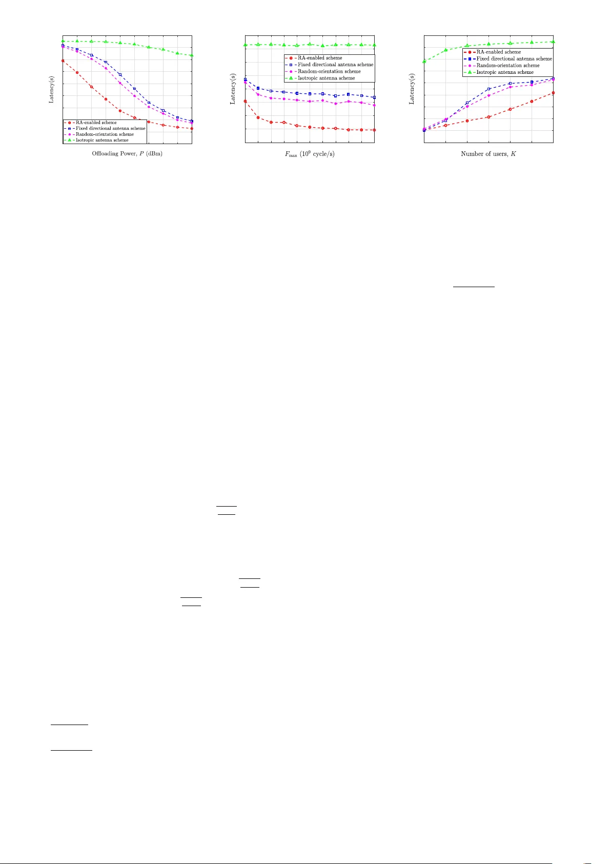
1 Rotatable Antenna-Enabled Mobile Edge Computing Qiyao W ang, Beixiong Zheng, Senior Member , IEEE , Xue Xiong, W eidong Mei, Member , IEEE , Changsheng Y ou, Member , IEEE , Qingqing W u, Senior Member , IEEE , and Jie T ang, Senior Member , IEEE Abstract —In the evolving landscape of mobile edge computing (MEC), enhancing communication reliability and computation efficiency to support increasingly stringent lo w-latency services remains a fundamental challenge. Rotatable antenna (RA) is a promising technology that introduces new spatial degrees- of-freedom (DoFs) to tackle this challenge. In this letter , we in vestigate an RA-enabled MEC system where antenna bore- sight directions can be independently adjusted to proactively impro ve wireless channel conditions f or latency-critical users. W e aim to minimize the maximum computation latency by jointly optimizing the MEC server’ s computing resource allocation, recei ve beamforming, and the deflection angles of all RAs. T o address the resulting non-conv ex problem, we develop an efficient alternating optimization (A O) framework. Specifically , the optimal edge computing resour ce allocation is derived based on the Karush–Kuhn–T ucker (KKT) conditions. Given the com- puting resour ces, the receiv e beamf orming is optimized using semidefinite relaxation (SDR) combined with a bisection search. Furthermore, the RA deflection angles are optimized via frac- tional programming (FP) and successiv e convex appr oximation (SCA). Simulation r esults verify that the pr oposed RA-enabled MEC scheme significantly reduces the maximum computation latency compared with conventional benchmark methods. Index T erms —Rotatable antenna (RA), mobile edge computing (MEC), latency minimization, antenna boresight. I . I N T RO D U C T I O N T o meet the ambitious vision of the forthcoming sixth- generation (6G) network featuring ubiquitous connectivity and ultra-low latency , mobile edge computing (MEC) has been widely regarded as a promising technology that offloads com- putation tasks from resource-limited de vices to nearby edge servers, thereby significantly reducing end-to-end latency and energy consumption [1], [2]. Howe ver , the performance of MEC systems is fundamentally constrained by the wireless links used for task of floading. The limited cov erage, channel capacity constraints, and dynamic network conditions can sev erely degrade the quality of service (QoS), especially for latency-sensiti ve applications. T o overcome these challenges, rotatable antenna (RA) tech- nology has recently emerged as an effecti ve approach to enhance spatial degrees of freedom (DoFs) by enabling each antenna to flexibly adjust its three-dimensional (3D) bore- sight direction [3]–[5]. Unlike con ventional fixed antennas, RAs can dynamically reshape their radiation patterns to fo- cus energy toward desired users and suppress interference, thereby improving link reliability and transmission ef ficiency . As a simplified yet practical member of the movable antenna (MA)/six-dimensional movable antenna (6DMA) family [6], [7], which preserves only rotational flexibility , RA of fers a compact and low-cost solution suitable for edge deployments. Owing to these advantages, RA technology has demonstrated notable performance gains in various wireless communication Qiyao W ang and Beixiong Zheng are with the School of Microelectronics, South China University of T echnology , Guangzhou 511442, China (e-mails: 202420165372@mail.scut.edu.cn; bxzheng@scut.edu.cn). Xue Xiong is with the School of Future T echnology , South China Univ ersity of T echnology , Guangzhou 511442, China (e-mail: ftxuex- iong@mail.scut.edu.cn). W eidong Mei is with the National Key Laboratory of Science and T echnol- ogy on Communications, Uni versity of Electronic Science and T echnology of China, Chengdu 611731, China (e-mail: wmei@uestc.edu.cn). Changsheng Y ou is with the Department of Electronic and Electrical Engi- neering, Southern University of Science and T echnology , Shenzhen 518055, China, and also with the Shenzhen Key Laboratory of Optoelectronics and Intelligent Sensing, Shenzhen 518055, China (e-mail: youcs@sustech.edu.cn). Qingqing W u is with the Department of Electronic Engineering, Shanghai Jiao T ong University , Shanghai 200240, China (e-mail: qingqingwu@sjtu.edu.cn). Jie T ang is with the School of Electronic and Information Engineering, South China University of T echnology , Guangzhou 510640, China (e-mail: eejtang@scut.edu.cn). Fig. 1. An RA-enabled MEC system. scenarios, such as physical layer security [8], integrated sens- ing and communication (ISA C) [9], beam-squint mitigation [10], and efficient channel estimation [11]. In particular, by flexibly adjusting the antenna boresight directions, RA can strengthen the wireless links of bottleneck users and mitigate unfa vorable channel conditions, thereby making it particularly suitable for latency-sensiti ve MEC systems. By improving the reliability and quality of the offloading links, RA further enables more adaptiv e and task-aware scheduling decisions in MEC systems, thereby significantly enhancing the ov erall com- putation efficienc y and responsi veness. Nev ertheless, despite these promising advantages, the integration of RA technology into MEC architectures remains largely unexplored. In partic- ular , how to jointly exploit RA directional control, wireless signal processing, and edge computing resource allocation to minimize computation latency remains an open problem. Motiv ated by the above, in this letter we study an RA- enabled MEC uplink communication system, where an RA array is deployed at the base station (BS) to flexibly adjust an- tenna boresight directions tow ard different users, as illustrated in Fig. 1. T o minimize the maximum computation latency , we formulate a joint optimization problem by optimizing the MEC server’ s computing resource allocation, the receive beamform- ing vectors, and the RAs’ deflection angles. T o solve the result- ing non-conv ex problem, we dev elop an alternating optimiza- tion (A O) framework, where the computing resource allocation subproblem is solved via the Karush–Kuhn–T ucker (KKT) conditions and the receiv e beamforming is optimized through semidefinite relaxation (SDR) and the bisection method, while the RA ’ s deflection angle subproblem is handled using frac- tional programming (FP) and successive con vex approximation (SCA) techniques. Simulation results verify that the proposed RA-enabled MEC scheme significantly reduces computation latency as compared to con ventional benchmarks. I I . S Y S T E M M O D E L A N D P RO B L E M F O R M U L A T I O N As sho wn in Fig. 1, we consider an RA-enabled MEC uplink communication system, where the BS is equipped with an edge computing server . Specifically , K devices simultaneously transmit data to the BS and may offload part or all of their computation tasks to the associated MEC serv er . The BS is equipped with a uniform planar array (UP A) consisting of N directional RAs, while each device is equipped with only a single isotropic antenna. Under the three-dimensional (3D) Cartesian coordinate system, we assume that the planar array is placed on the y - z plane with N ≜ N y N z , where N y and N z denote the numbers of RAs along y - and z - axes, respecti vely , and the reference orientation/boresight of each RA is assumed to be parallel to the positiv e x -axis. Let p n ∈ R 3 × 1 and q k ∈ R 3 × 1 be the reference positions of the n -th RA and the k -th device, respectively . The deflection angle vector of the n -th RA is defined as θ n ≜ [ θ e n , θ a n ] T , 2 n = 1 , . . . , N , where θ e n represents the zenith angle between the boresight direction of the n -th RA and the x -axis, and θ a n denotes the azimuth angle between the projection of the boresight vector of RA n onto the y - z plane and the z -axis. Accordingly , the pointing vector of each RA can be defined as f ( θ n ) = [ cos( θ e n ) , sin( θ e n ) sin( θ a n ) , sin( θ e n ) cos( θ a n ) ] T . T o account for the antenna boresight adjustment range, the zenith angle of each RA is constrained within a prescribed range, giv en by 0 ≤ θ e n ≤ θ max , ∀ n , where θ max denotes the maximum allowable zenith angle. For notational con venience in the subsequent analysis, we introduce an auxiliary variable f n ∈ R 3 × 1 to represent RA pointing vector associated with θ n , i.e., f n = f ( θ n ) , with ∥ f n ∥ = 1 . A. Communication Model W e consider an uplink communication model, where the computation offloading of the K devices is performed over a predefined frequency bandwidth B and shares the same time resource. All device-to-BS links are assumed to experience quasi-static flat-fading channels. Accordingly , the channel be- tween device k and RA n can be modeled as h k,n ( f n ) = q L ( d k,n ) g k,n , (1) where L ( d k,n ) = ζ 0 ( d 0 /d k,n ) α 0 represents the large-scale channel power gain, ζ 0 is the channel power gain at the reference distance of d 0 = 1 meter (m), α 0 denotes the path loss exponent, and d k,n represents the distance from the k -th device to the n -th RA. Furthermore, we assume that g k,n follows an independent Rician fading model with Rician factor κ k , giv en by g k,n = r κ k κ k + 1 ¯ g k,n + r 1 κ k + 1 ˜ g k,n , (2) where ¯ g k,n = p G k,n e − j 2 π λ d k,n represents the line-of-sight (LoS) channel component, ˜ g k,n ∼ C N (0 , 1) denotes the non- LoS (NLoS) channel component characterized by Rayleigh fading, and λ is the signal w avelength. In addition, G k,n denotes the generic directional radiation pattern for each RA, which can be modeled as [4] G ( ϵ, ϕ ) = G 0 cos 2 p ( ϵ ) , ϵ ∈ [0 , π / 2) , ϕ ∈ [0 , 2 π ) , 0 , otherwise, (3) where ϵ and ϕ are the zenith and azimuth angles of any spatial directions with respect to the RA ’ s boresight direction, G 0 is the maximum gain in the boresight direction (i.e., ϵ = 0 ) with G 0 = 2(2 p + 1) satisfying the la w of power conservation, and p ≥ 0 determines the directivity of antenna. Additionally , cos( ϵ k,n ) ≜ f T n q k,n is the projection between the device k ’ s direction vector q k,n ≜ q k − p n ∥ q k − p n ∥ and the pointing vector of RA n . Let F ≜ h f 1 , f 2 , . . . , f N i ∈ R 3 × N denote the RA deflection matrix. The ov erall channel from BS to device k is given by h k ( F ) = h h k, 1 ( f 1 ) , h k, 2 ( f 2 ) , . . . , h k,N ( f N ) i T . (4) Denote the uplink offloading transmit power and transmitted symbol of device k by P k and s k , respecti vely , the recei ved signal at the BS is expressed as y = K X k =1 h k ( F ) p P k s k + n , (5) where n ∼ C N (0 , σ 2 I N ) represents the additiv e white Gaus- sian noise (A WGN) with zero-mean and variance σ 2 . Upon receiving y , the BS applies a linear recei ve beamforming vector w H k ∈ C 1 × N with ∥ w k ∥ = 1 to extract the signal of device k , i.e., y k = w H k h k ( F ) p P k s k + K X j =1 ,j = k w H k h j ( F ) p P j s j + w H k n . (6) Then, the signal-to-interference-plus-noise ratio (SINR) for decoding the signal from the k -th device is giv en by γ k ( w k , F ) = P k w H k h k ( F ) 2 P K j =1 ,j = k P j w H k h j ( F ) 2 + σ 2 . (7) Accordingly , the maximum achiev able computation of floading rate of the k -th device is giv en by R k ( w k , F ) = B log 2 (1 + γ k ( w k , F )) . (8) B. Computing Model W e consider that each de vice k has a computation task consisting of L k bits, where processing each bit requires c k CPU cycles. The task can be divided into two parts: one computed locally at the de vice and the other offloaded to the edge server . 1) Local Computing: Let ℓ k (in bits) and f l k (in cycle/s) denote the task of floaded to the MEC server and CPU frequency of device k , respectively . Accordingly , the time required for undertaking the local computation is defined as D l k ( ℓ k ) = ( L k − ℓ k ) c k /f l k . 2) Edge Computing: W e assume that the edge computing for the k -th device commences only after all its task bits have been fully of floaded. Specifically , the total latency of edge computing contains two parts: the data transmission time from the device to the BS and the computation time at the MEC server . The MEC server allocates computing resource f e k for device k , which satisfies: K X k =1 f e k ≤ F max , f e k ≥ 0 , ∀ k , (9) where F max denotes the maximum computing capacity of the MEC server . In this work, the size of the computation result is assumed to be sufficiently small, such that we can neglect the feedback delay . Therefore, the ov erall latency associated with task offloading and edge computing is expressed as D e k ( w k , F , ℓ k , f e k ) = ℓ k /R k ( w k , F ) + ℓ k c k /f e k . Assuming that each device can perform local computa- tion and task offloading simultaneously , the task completion time is determined by the slower processing branch. Hence, the ov erall computation latency of device k is giv en by D k ( w k , F , ℓ k , f e k ) = max D l k ( ℓ k ) , D e k ( w k , F , ℓ k , f e k ) , and the maximum computation latency among all the devices is giv en by τ comp = max { D k ( w k , F , ℓ k , f e k ) , ∀ k } . C. Pr oblem F ormulation In this paper , we aim to minimize the maximum computation latency τ comp by jointly optimizing the computation offloaded data size ℓ = [ ℓ 1 , ℓ 2 , . . . , ℓ K ] T , the edge computing resource allocation for all devices f e = [ f e 1 , f e 2 , . . . , f e K ] T , the BS re- ceiv e beamforming matrix W = [ w 1 , w 2 , . . . , w K ] T , and the RA pointing matrix F . The associated optimization problem can be formulated as (P1) min ℓ , f e , W , F τ comp (10a) s.t. || w k || = 1 , ∀ k , (10b) 0 ≤ arccos( f T n e 1 ) ≤ θ max , ∀ n, (10c) ∥ f n ∥ = 1 , ∀ n, (10d) ℓ k ∈ { 0 , 1 , . . . , L k } , k = 1 , 2 , . . . , K , (10e) K X k =1 f e k ≤ F max , (10f) f e k ≥ 0 , k = 1 , 2 , . . . , K, (10g) where constraint (10b) imposes the unit-norm constraints on receiv e beamforming vectors; (10c) specifies the maximum zenith angle that each RA is allowed to adjust and (10d) ensures that f n is a unit vector; (10e) ensures that the com- putation of floaded data size is an integer within the range from 0 to L k for the k -th device; (10f) and (10g) restrict the range of the edge computing resources allocated to each device. Due to the strong coupling v ariables and the non- con vex constraints, problem (P1) is non-con vex and difficult to handle. T o solve this problem, we propose an A O algorithm to iterativ ely optimize the four blocks of variables. 3 I I I . P RO P O S E D A L G O R I T H M F O R P R O B L E M ( P 1 ) In this section, we de velop an A O-based algorithm for solving problem (P1), which alternately optimizes computa- tion variables, i.e. { ℓ , f e } , and communication variables, i.e. { W , F } in an iterati ve manner until con vergence. Accordingly , problem (P1) can be decomposed into two tractable subprob- lems. A. Joint Optimization of Offloaded Data Size and Edge Com- puting Resour ce Allocation Giv en the recei ve beamforming matrix W and the RAs’ pointing matrix F , problem (P1) can be reduced to (P2) min ℓ , f e τ comp (11) s.t. (10e), (10f), (10g) . Although problem (P2) is simplified, it remains challenging to solve optimally since the variables ℓ and f e are still coupled in (10e)-(10g). T o decouple them, we first fix f e and optimize ℓ . Under this condition, (P2) reduces to a set of single-variable optimization problems with respect to ℓ k , each of which admits a closed-form solution [12], as giv en by ℓ ⋆ k = argmin ˆ ℓ k ∈ { ⌊ ˆ ℓ ⋆ k ⌋ , ⌈ ˆ ℓ ⋆ k ⌉ } D k ( ˆ ℓ k ) , (12) where ⌊·⌋ and ⌈·⌉ represent the floor and ceiling operations, respectiv ely , and ˆ ℓ ⋆ k is giv en by ˆ ℓ ⋆ k = L k c k R k f e k f e k f l k + c k R k ( f e k + f l k ) . (13) By substituting ˆ ℓ ⋆ k into (10a) and introducing the slack vari- able t 1 , problem (P2) can be transformed into the following problem (P2.1) min f e ,t 1 t 1 (14a) s.t. L k c 2 k R k + L k c k f e k f e k f l k + c k R k f e k + f l k ≤ t 1 , ∀ k , (14b) (10f), (10g) . It can be verified that problem (P2.1) is con vex, since the left-hand side of constraint (14b) is con vex with respect to f e k , while all other constraints are affine. Therefore, the KKT conditions can be applied to derive the closed-form solution of f e k . Due to the min–max latency objective, only the multiplier associated with the bottleneck device is acti ve, while the multipliers of all the other devices equal zero. W ithout loss of generality , we normalize the activ e multiplier to unity . Accordingly , the optimal f e k for a gi ven dual v ariable µ is giv en in closed form as in [12] f e k = q L k c 3 k R 2 k µ − c k R k f l k f l k + c k R k , k = 1 , . . . , K, (15) where µ ⋆ denotes the optimal dual variable and can be found via bisection search within the interval ( µ l , µ u ] = 0 , min k L k c k f l k 2 . B. Joint Optimization of Receive Beamforming and P ointing Matrix Giv en the offloaded data size ℓ and the edge computing resource allocation vector f e , problem (P1) is reformulated as the following optimization problem for optimizing the receiv e beamforming matrix W and the RA pointing matrix F . (P3) min W , F τ comp (16) s.t. (10b), (10c), (10d) . As shown in Section III-A, at the optimal solution to problem (P2), D l k = D e k , and thus the objective in (16) can be equiv alently expressed solely in terms of the edge computation latency . By replacing D k with D e k , and replacing ℓ k with the closed-form ˆ ℓ ⋆ k from (13), problem (P3) reduces to (P3.1) min W , F max k L k c k f e k f e k f l k + c k R k ( w k , F )( f e k + f l k ) + ℓ k c k f e k (17) s.t. (10b), (10c), (10d) . Moreov er, due to the complicated fractional SINR expres- sion shown in (7), we introduce a set of slack variables t 2 and { t 3 ,k } to reformulate problem (P3.1) as (P3.2) min W , F ,t 2 , { t 3 ,k } t 2 (18a) s.t. ℓ k c k f e k ≤ t 3 ,k , ∀ k , (18b) L k c k f e k f e k f l k + c k R k ( w k , F )( f e k + f l k ) + t 3 ,k ≤ t 2 , ∀ k , (18c) R k ≤ B log 2 (1 + γ k ) , ∀ k , (18d) γ k ≤ P k w H k h k ( F ) 2 P K j =1 ,j = k P j | w H k h j ( F ) | 2 + σ 2 , ∀ k , (18e) (10b), (10c), (10d) . Problem (P3.2) is still non-conv ex due to the coupled variables and the fractional SINR constraint in (18e). T o address this issue, we further decompose problem (P3.2) into two subprob- lems. 1) Receive Beamforming Optimization Giv en the pointing matrix F , the SINR constraints reduce to γ k ≤ P k w H k h k 2 P K j =1 ,j = k P j | w H k h j | 2 + σ 2 , ∀ k . (19) T o facilitate con vex reformulation, we define W k = w k w H k , which satisfies W k ⪰ 0 and rank( W k ) = 1 . Note that w H k h k 2 = tr( W k H k ) and w H k h j 2 = tr( W k H j ) , where H k = h k h H k and H j = h j h H j . The rank-one constraint is non-con vex, we relax it to obtain the following SDR problem: (P3.3) min W ,t 2 , { t 3 ,k } t 2 (20a) s.t. γ k ( K X j =1 ,j = k P j tr( W k H j ) + σ 2 ) ≤ P k tr( W k H k ) , ∀ k , (20b) tr( W k ) = 1 , ∀ k . (20c) W k ⪰ 0 , ∀ k , (20d) (18b), (18c), (18d) . It can be verified that problem (P3.3) is a quasi-con ve x optimization problem with respect to { W k } , which can be solved via bisection search. Specifically , for any given γ k , the feasibility problem associated with (P3.3) can be reformulated as a conv ex semidefinite program (SDP). Although the SDR may result in a high-rank solution, a high-quality rank-one approximation can be recov ered using Gaussian randomiza- tion, which is then used to obtain the corresponding recei ve beamforming vectors. 2) P ointing Matrix Optimization For a giv en recei ve beamforming matrix W , problem (P3.2) can be equiv alently expressed as (P3.4) min F ,t 2 , { t 3 ,k } t 2 (21a) s.t. γ k ≤ P k w H k h k ( F ) 2 P K j =1 ,j = k P j | w H k h j ( F ) | 2 + σ 2 , ∀ k (21b) cos( θ max ) ≤ f T n e 1 ≤ 1 , ∀ n, (21c) (10d), (18b), (18c), (18d) . where constraint (21c) is equiv alent to (10c) and restricts RA ’ s zenith angle within [0 , θ max ] . Due to the fractional structure of the SINR expression in constraint (21b), we apply the quadratic transform, yielding f k ( F , η k ) = 2 R n η k √ P k w H k h k ( F ) o − | η k | 2 K X j =1 ,j = k P j w H k h j ( F ) 2 + σ 2 , (22) where η k is an auxiliary variable introduced by the quadratic transform for each device k . W e then iterativ ely optimize F and { η k } to minimize the objectiv e function in (21a). For a 4 giv en F , the optimal auxiliary v ariable η k has the follo wing closed-form expression [13]: η ⋆ k = √ P k w H k h k ( F ) P K j =1 ,j = k P j w H k h j ( F ) 2 + σ 2 . (23) For fixed η ⋆ k , the remaining problem with respect to F is still non-con vex due to the nonlinear dependence of h k ( F ) on the RA pointing vectors. T o address this issue, we adopt the SCA technique to construct a con vex approximation of problem (P3.4). Let F ( i ) denote the RA pointing matrix obtained at the i -th iteration. By using the first-order T aylor expansion at F ( i ) , the term w H k h k ( F ) in (22) can be approximated as Φ ( i +1) k ( F ) ≜ w H k h k ( F ( i ) ) + N X n =1 w ∗ k,n ( h ′ k,n ) T ( f n − f ( i ) n ) , (24) where h ′ k,n = ∂ h k,n ( f ( i ) n ) ∂ f ( i ) n = ˜ β k,n p ( f ( i ) n ) T q k,n p − 1 q k,n , with ˜ β k,n ≜ q κ k κ k +1 p L ( d k,n ) G 0 e − j 2 π λ d k,n , and ( · ) ∗ repre- sents the conjugation operation. Furthermore, to handle the non-con vex constraint in (21b), we construct a quadratic conv ex upper bound for u k,j ( F ) ≜ w H k h j ( F ) 2 . Let ∇ u k,j ( f n ) and ∇ 2 u k,j ( f n ) denote the gra- dient vector and Hessian matrix of u k,j with respect to f n , respectively , whose detailed deriv ations are provided in Appendix A. Specifically , for a positive real number δ k,j,n satisfying δ k,j,n I 3 ⪰ ∇ 2 u k,j ( f n ) , whose closed-form expres- sion is giv en in Appendix B, we hav e the following quadratic upper bound: u k,j ( f n ) ≤ u k,j ( f ( i ) n ) + ∇ u k,j ( f ( i ) n ) T ( f n − f ( i ) n ) + δ k,j,n 2 ( f n − f ( i ) n ) T ( f n − f ( i ) n ) ≜ u ub k,j ( f n ) , (25) which is obtained based on [14, Lemma 12]. Then, the expression (22) can be approximated as f k ( F , η k ) ≥ 2 R n η H k p P k Φ ( i +1) k ( F ) o − | η k | 2 K X j =1 ,j = k P j u ub k,j ( F ) + σ 2 , (26) where u ub k,j ( F ) denotes the constructed con vex upper bound applied to RA pointing matrix F . C. Overall Algorithm Algorithm 1 Joint Optimization of ℓ , f e , W , F . Initialize Set F (0) = [ e 1 , . . . , e 1 ] 3 × N , threshold ε > 0 , and i = 0 . Compute ℓ (0) and f e (0) by the closed-form solutions in (13) and (15). repeat Compute W ( i +1) by solving problem (P3.3) with given ℓ ( i ) , f e ( i ) , and F ( i ) . Update F ( i +1) by solving problem (P3.4) with given ℓ ( i ) , f e ( i ) , and W ( i +1) . Calculate ℓ ( i +1) and f e ( i +1) by the closed-form solution in (13) and (15) with given W ( i +1) and F ( i +1) . Update i = i + 1 . until τ comp ( i +1) − τ comp ( i ) τ comp ( i ) ≤ ε. Integerize ℓ ( i ) by (12). Output ℓ ( i ) , f e ( i ) , W ( i ) and F ( i ) . The ov erall A O algorithm for solving (P1) is summarized in Algorithm 1. Since the objective function τ comp is non- increasing ov er iterations and lower bounded, the proposed A O algorithm is guaranteed to conv erge. In each iteration, the computational complexity of solving problem (P2) is O I log 2 µ u − µ l ϵ 1 K , where ϵ 1 is the accurac y of the bi- section search and I is the number of inner iterations. The complexity order of problem (P3.3) via the SDR and bisection methods is O ( N 4 . 5 ln(1 /ϵ 2 )) , while that of problem (P3.4) via the SCA method is O ( N 3 . 5 ln(1 /ϵ 3 )) , with ϵ 2 and ϵ 3 being the accuracy thresholds of the bisection search and the SCA method, respectiv ely . Therefore, the o verall computational complexity of solving (P1) is O ( L · ( I log 2 µ u − µ l ϵ 1 K + N 4 . 5 ln(1 /ϵ 2 ) + N 3 . 5 ln(1 /ϵ 3 )) , where L denotes the number of outer A O iterations required for conv ergence. I V . S I M U L A T I O N R E S U LT S In this section, we present simulation results to verify the performance of our proposed RA-enabled MEC uplink communication system with the proposed A O algorithm. The RA array is centered at the origin, with an inter-antenna spacing of d = λ 2 , p = 4 , and θ max = π 6 . The system operates at 2.4GHz ( λ = 0 . 125 m) with noise power σ 2 = − 60 dBm. Unless otherwise specified, the simulation parameters are set as follows: N = 9 , ζ 0 = − 30 dB, α 0 = 2 . 8 , κ k = 1 , ∀ k , B = 2 MHz. W e set L k = 1000 Kb, c k = 1000 cycle/bit, and f l k = 6 × 10 8 cycle/s for all de vices. The offloading transmit po wers of all devices are assumed to be identical, i.e., P k = P , ∀ k . The devices are assumed to be uniformly distributed o ver a semicircle centered at the origin with a radius of r = 40 m. For a more comprehensiv e ev aluation of the proposed RA- enabled MEC system (referred to as RA-enabled scheme ), the following three schemes are considered: 1) Fixed directional antenna scheme: The deflections of all RAs are fixed as f n = e 1 , ∀ n . 2) Isotropic antenna scheme: The directional gain is set to G 0 = 1 with p = 0 in (3). 3) Random-orientation scheme: The orientation of each RA is randomly generated within the rotational ranges specified in (10c). In Fig. 2, we show the latencies of dif ferent schemes versus the of floading po wer P for K = 4 and F max = 30 × 10 9 cycle/s. It is observed that the latencies of all schemes decrease with increasing of floading power , since a higher po wer improves the uplink offloading rate. It is worth noting that the performance gap between the proposed RA-enabled scheme and the bench- mark schemes becomes less pronounced at very low and high offloading po wer . At lo w of floading po wer, noise dominates the link quality , making the directional gain insufficient to produce noticeable improvement. While at high offloading power , the latency is mainly constrained by the maximum computation capacity , the offloading communication capability is no longer the bottleneck, so the array directional gain provided by RA becomes less critical. Furthermore, the RA-enabled scheme always outperforms the benchmark schemes. This is primarily owing to the ability of RAs to adaptiv ely rotate their boresight directions, which enhances the effecti ve uplink channel gain and increases the offloading rate, thereby reducing the commu- nication latency . In contrast, the isotropic antenna scheme and fixed directional antenna scheme exhibit higher latency due to the absence of directional enhancement, while the random- orientation scheme fails to fully exploit the directional gain owing to its non-optimized antenna orientations. Fig. 3 illustrates the maximum computation latency versus the maximum computing capacity F max for K = 4 and P = 3 dBm. As F max increases, the latencies of all schemes decrease due to the shortened task execution time at the edge server . When F max is not high, the computing capability is the bottleneck of latency reduction. But when F max is high enough, the reduction of the latency becomes small which means that the of floading communication capability plays a dominant role. Therefore, it is not necessary to equip the edge computing node with an extremely powerful computing capability for latency minimization. Fig. 4 shows the latencies of different schemes versus the number of devices K for P = 3 dBm and F max = 30 × 10 9 cycle/s. It is observ ed that the RA-enabled scheme con- sistently outperforms all benchmark schemes, and the latency of each scheme increases with K . This is partially due to the 5 -12 -9 -6 -3 0 3 6 9 12 15 0 0.2 0.4 0.6 0.8 1 1.2 1.4 1.6 1.8 Fig. 2. The maximum computation latency versus offloading po wer. 5 10 15 20 25 30 35 40 45 50 55 0.2 0.4 0.6 0.8 1 1.2 1.4 1.6 1.8 Fig. 3. The maximum computation latency versus the maximum computing capacity . 1 2 3 4 5 6 7 0 0.2 0.4 0.6 0.8 1 1.2 1.4 1.6 1.8 Fig. 4. The maximum computation latency versus number of devices. reduced edge computational resources allocated to each de vice. Moreov er, the antenna deflection adjustment becomes more challenging, making it difficult to simultaneously enhance the directional gains for all devices. In addition, when K becomes large, the performance advantage of the RA-enabled scheme ov er the fixed directional and random-orientation schemes gradually diminishes, since the system becomes increasingly dominated by resource sharing and multi-user competition rather than antenna deflection optimization. V . C O N C L U S I O N In this letter , we in vestigated an RA-enabled MEC uplink system, where each RA at the BS can flexibly adjust its boresight direction to enhance uplink channel quality for multiple users. By jointly optimizing the MEC server’ s com- puting resource allocation, receiv e beamforming vectors, and the RAs’ deflection angles, we developed an efficient A O framew ork to minimize the maximum computation latency . Simulation results demonstrated that the proposed RA-enabled MEC design significantly improv es latency performance over con ventional schemes, highlighting its effecti veness to enable low-latenc y and high-efficienc y computing services in future 6G networks. A P P E N D I X A. Derivations of ∇ u k,j ( f n ) and ∇ 2 u k,j ( f n ) For the sake of exposition, we reformulated u k,j ( F ) as u k,j ( F ) = N X n =1 w ∗ k,n ˜ β j,n ( f T n q j,n ) p + q 1 κ j +1 ˜ g j,n 2 , (27) T o optimize with respect to a specific f n , we fix the other variables f m for m = n and consider u k,j as a function of f n only . T o facilitate the subsequent deriv ations, we introduce the following auxiliary v ariables based on f n : b n ≜ f T n q j,n , c n ≜ w ∗ k,n ˜ β j,n , ξ n ≜ w ∗ k,n q 1 κ j +1 ˜ g j,n , and d n ≜ P m = n w ∗ k,m ˜ β j,m b p m + q 1 κ j +1 ˜ g j,m . Thus, the objectiv e function can be written as u k,j ( f n ) = | d n + ξ n + c n b p n | 2 . For conv enience, we let ¯ d n ≜ d n + ξ n and expand this expression, we obtain: u k,j ( f n ) = | ¯ d n | 2 + 2 R ( ¯ d n c ∗ n ) b p n + | c n | 2 b 2 p n . (28) By defining the real coefficients as A n = | ¯ d n | 2 , B n = 2 R ( ¯ d n c ∗ n ) , and C n = | c n | 2 , we arriv e at a simplified form: u k,j ( f n ) = A n + B n b p n + C n b 2 p n . (29) T aking deriv ativ es of (29) with respect to b n , we obtain: ∂ u k,j ( f n ) ∂ b n = B n pb p − 1 n + 2 C n pb 2 p − 1 n = pb p − 1 n ( B n + 2 C n b p n ) , (30) ∂ 2 u k,j ( f n ) ∂ b 2 n = p ( p − 1) B n b p − 2 n + 2 p (2 p − 1) C n b 2 p − 2 n . (31) Applying the chain rule and noting that ∇ f n b n = q j,n , the gradient vector ∇ u k,j ( f n ) and the Hessian matrix ∇ 2 u k,j ( f n ) are: ∇ u k,j ( f n ) = pb p − 1 n ( B n + 2 C n b p n ) q j,n , (32) ∇ 2 u k,j ( f n ) = p ( p − 1) B n b p − 2 n + 2 p (2 p − 1) C n b 2 p − 2 n q j,n q T j,n . (33) B. Construction of δ k,j,n Based on the definition of ∇ 2 u k,j ( f n ) in Appendix A, we hav e ∥∇ 2 u k,j ( f n ) ∥ 2 ≤ ∥∇ 2 u k,j ( f n ) ∥ F . (34) Since q j,n is a unit-norm vector , the matrix q j,n q T j,n is rank- one with a single nonzero eigenv alue equal to 1. Therefore, the spectral norm of ∇ 2 u k,j ( f n ) equals the absolute value of its scalar coefficient, which is giv en by ∇ 2 u k,j ( f n ) 2 = ∂ 2 u k,j ( f n ) ∂ b 2 n . (35) T o ensure a positi ve semidefinite majorization condition δ k,j,n I 3 ⪰ ∇ 2 u k,j ( f n ) , we can directly select δ k,j,n as δ k,j,n = p ( p − 1) B n b p − 2 n + 2 p (2 p − 1) C n b 2 p − 2 n , (36) which guarantees δ k,j,n I 3 ⪰ ∇ 2 u k,j ( f n ) , and hence δ k,j,n ≥ ∥∇ 2 u k,j ( f n ) ∥ 2 . This choice ensures that δ k,j,n serves as a valid local Lipschitz constant for the gradient mapping, i.e., ∥∇ u k,j ( f n ) − ∇ u k,j ( f ( i ) n ) ∥ ≤ δ k,j,n ∥ f n − f ( i ) n ∥ . R E F E R E N C E S [1] Y . Mao, C. Y ou, J. Zhang, K. Huang, and K. B. Letaief, “ A survey on mobile edge computing: The communication perspective, ” IEEE Commun. Surveys T uts. , vol. 19, no. 4, pp. 2322–2358, 4th Quart. 2017. [2] C. Y ou, K. Huang, H. Chae, and B.-H. Kim, “Energy-efficient resource allocation for mobile-edge computation offloading, ” IEEE T rans. W ire- less Commun. , vol. 16, no. 3, pp. 1397–1411, May . 2017. [3] Q. W u, B. Zheng, T . Ma, and R. Zhang, “Modeling and optimization for rotatable antenna enabled wireless communication, ” in Pr oc. IEEE Int. Conf. Commun. (ICC) , Montreal, Canada, Jun. 2025, pp. 1055–1060. [4] B. Zheng, Q. Wu, T . Ma, and R. Zhang, “Rotatable antenna enabled wireless communication: Modeling and optimization, ” arXiv preprint arXiv:2501.02595 , 2025. [5] B. Zheng, T . Ma, C. Y ou, J. T ang, R. Schober , and R. Zhang, “Rotatable antenna enabled wireless communication and sensing: Opportunities and challenges, ” IEEE W ireless Commun. , pp. 1–8, Oct. 2025. [6] L. Zhu, W . Ma, and R. Zhang, “Modeling and performance analysis for mov able antenna enabled wireless communications, ” IEEE T rans. W ireless Commun. , vol. 23, no. 6, pp. 6234–6250, Nov . 2024. [7] X. Shao, Q. Jiang, and R. Zhang, “6D movable antenna based on user distribution: Modeling and optimization, ” IEEE T rans. W ireless Commun. , vol. 24, no. 1, pp. 355–370, Jan. 2025. [8] L. Dai, B. Zheng, Q. Wu, C. Y ou, R. Schober , and R. Zhang, “Ro- tatable antenna-enabled secure wireless communication, ” IEEE Wir eless Commun. Lett. , vol. 14, no. 11, pp. 3440–3444, Jul. 2025. [9] C. Zhou, C. Y ou, B. Zheng, X. Shao, and R. Zhang, “Rotatable antennas for integrated sensing and communications, ” IEEE W ireless Commun. Lett. , vol. 14, no. 9, pp. 2838–2842, Jun. 2025. [10] Y . Xie, W . Mei, D. W ang, B. Ning, Z. Chen, J. Fang, and W . Guo, “Thz beam squint mitigation via 3D rotatable antennas, ” in Pr oc. IEEE International Conference on Communications W orkshops (ICC W orkshops) , Montreal, QC, Canada, Jun. 2025, pp. 26–31. [11] X. Xiong, B. Zheng, W . W u, X. Shao, L. Dai, M.-M. Zhao, and J. T ang, “Ef ficient channel estimation for rotatable antenna-enabled wireless communication, ” IEEE W ireless Commun. Lett. , vol. 14, no. 11, pp. 3719–3723, Aug. 2025. [12] T . Bai, C. Pan, Y . Deng, M. Elkashlan, A. Nallanathan, and L. Hanzo, “Latency minimization for intelligent reflecting surface aided mobile edge computing, ” IEEE J. Sel. Areas Commun. , vol. 38, no. 11, pp. 2666–2682, Jul. 2020. [13] K. Shen and W . Y u, “Fractional programming for communication systems—part I: Power control and beamforming, ” IEEE T rans. Signal Pr ocess. , vol. 66, no. 10, pp. 2616–2630, May 2018. [14] Y . Sun, P . Babu, and D. P . Palomar , “Majorization-minimization algo- rithms in signal processing, communications, and machine learning, ” IEEE T rans. Signal Process. , vol. 65, no. 3, pp. 794–816, Aug. 2016.
Original Paper
Loading high-quality paper...
Comments & Academic Discussion
Loading comments...
Leave a Comment