Clutter-Aware Integrated Sensing and Communication: Models, Methods, and Future Directions
Integrated sensing and communication (ISAC) can substantially improve spectral, hardware, and energy efficiency by unifying radar sensing and data communications. In wideband and scattering-rich environments, clutter often dominates weak target refle…
Authors: Rang Liu, Peishi Li, Ming Li
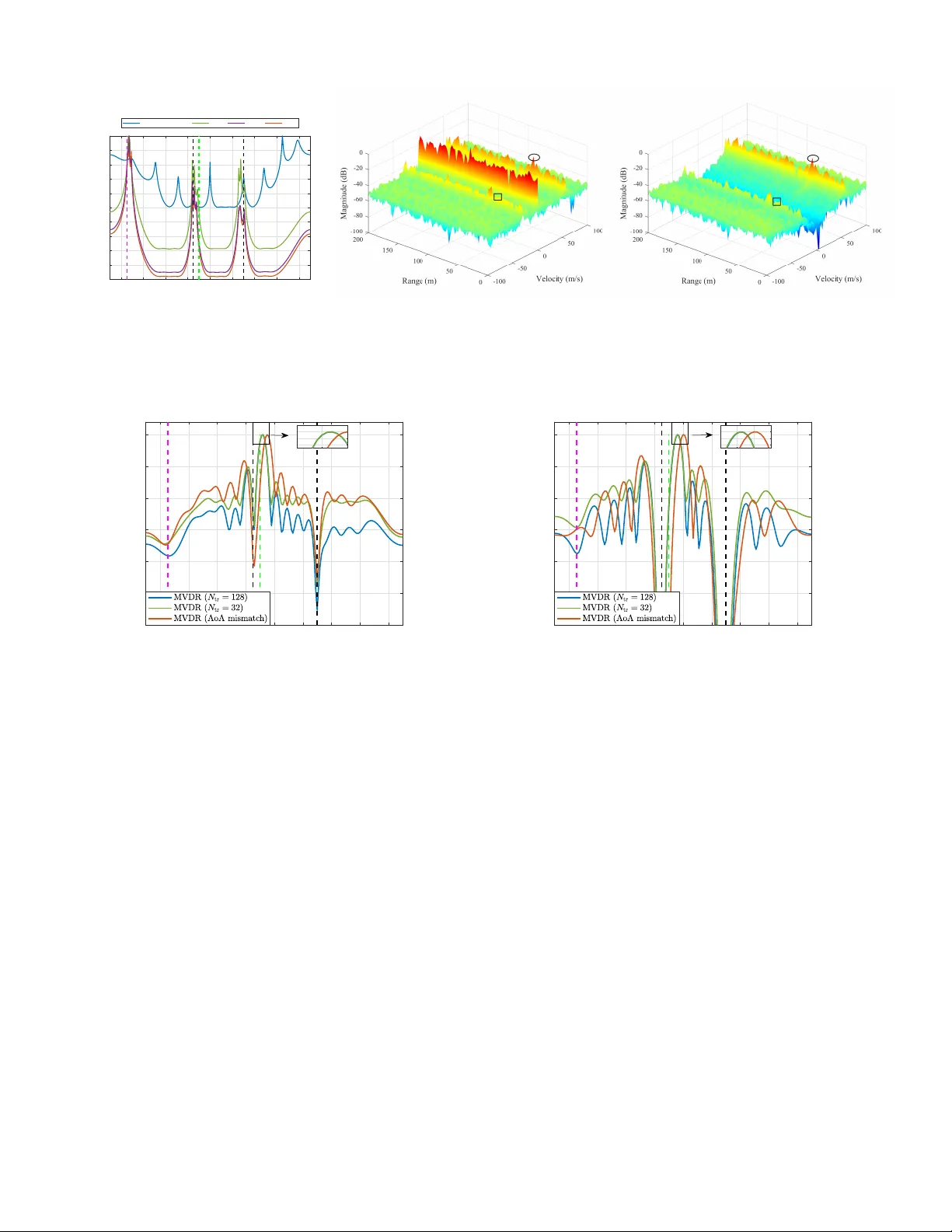
1 Clutter -A wa re Inte grated Sensing and Communication: Models, Methods, and Future Directi ons Rang Liu, Member , I EEE, Peishi Li, Ming Li, Senior Member , IEEE, and A. Lee Swindlehurst, Life F ellow , IEEE Abstract —Integrated sensing and communication (ISA C) can substantially impro ve spectral, hardware, a nd energy efficiency by unifying radar sensing and data communi cations. In wideband and scattering-rich en vironments, clutter often dominates weak target reflections and becomes a fundamental bottleneck for reliable sensing. Practical IS A C clutter inclu des “cold” clutter arising from en vironmental backscatter of the probing wa vef orm, and “hot” clutter indu ced by external in terference and reflections from the enviro nment whose statistics can va ry ra pidly o ver time. In thi s article, we de velop a unified wid eband multiple- input multipl e-out put orthogonal frequency-division multiplexing (MIMO-OFDM) signal model that captures b oth clu tter types acros s the space, time, and frequency domains. Bu i lding on this model, we review clutter characteriza tion at multiple lev els, in- cluding amplitude statistics, robust spherically inv ariant random vector (SIR V) modeling, and structured cov ariance repr esenta- tions suitable for limited-snapsh ot regimes. W e t hen summarize recei ver -side su ppression methods in the temporal and spatial do- mains, together with extensions t o space-time adaptive processing (ST AP ) and space-fre quency-time adaptive p rocessing (SFT AP), and we p ro vide guidance on selecting techniques under different wa vef orm and interference conditi ons. T o mov e beyo nd reactiv e suppression, w e discuss clutter-awar e transceiver co-design t h at couples b eamf orming and wav efo rm optimization with p ractical communication quality-of-service (QoS) constraints to enable proacti ve clutter a vo idance. W e conclude with open challenges and rese arch directions toward en vironment-adaptive and clutter- resilient ISA C for next-generation networks. Index T erms —In t egrated sensi n g and communication (ISA C), clutter modeling, clutter su ppression, wideband MIM O-OF DM, beamf orming/wa vef orm optimization. I . I N T R O D U C T I O N Integrated sensing and commun ication (I SA C) r efers to the unified use of wireless resour ces for rad ar sensing and d a ta commun ication within the sam e system , facilitating a mutual trade-off between these two function alities [1]–[5]. By inte- grating sensin g and com munication into a sing le infr astructure, ISA C significan tly improves spectru m, energy , and h ardware efficiency , while concu rrently red ucing signaling overhea d and deployment costs. The dedicated spectrum and ha r dware resources conv entionally assigned separately to radar a n d commun ication are shared , en abling dual-fun ctional “green” networks and co st-effecti ve hardware p latforms [ 6]. Beyond R. Liu and A. Lee Swindlehurst are with the Nhu Department of E lectri cal Engineeri ng and Computer Science, Uni v ersity of California, Irvi ne, CA 92697, USA (e-mail: rangl2@uc i.edu; swindle@uc i.edu). P . Li and M. Li are with the School of Information and Communicati on Engineeri ng, Dalian Univ ersit y of T echnology , Dalian 116024, China (e-mail: lipei shi@mail.dlut .edu.cn; mli@dlu t.edu.cn). resource efficienc y , ISA C also targets a deepe r integration in which the sensing and communication subsystems are jointly designed. Su c h integration supports commu nication-a ssisted sensing and sensing -assisted co mmunicatio n, lead ing to g a ins beyond what either system c a n achieve alon e [7]. The ISA C co ncept h a s attracted con siderable attention as an enab ling techn ology for next-generatio n 6G wireless networks. Recen t re sear ch ad vances h av e su bstantially ex- panded the range of ISAC app lication scenarios to include automotive sensing for in telligent transportation , vehicle-to- ev erything (V2X) co mmunica tio ns, uncrewed aerial vehicle (U A V) networks, smart homes, smar t factories, and huma n - centered sensing such as gesture or activity rec o gnition. These developments hav e stimulated stand ardization activities in bodies such as the 3rd Generation Partnership Project ( 3GPP) and IEEE toward integrating du al-function al capab ilities into future wireless network specifications. International organ i- zations such as the In ternationa l T elecom munication Union (ITU) hav e also identified I SAC as an in tegral part of the ir 6G vision, highligh ting sensing as a n ati ve cap ability of future intelligent and perceptive networks. A fundam e ntal challen ge fo r ISA C systems is clutter, which refers to un desired echo es and interferen ce that ob scure the target of intere st [8]–[10]. Th e distinction b etween targets and clutter is task-dependen t. Scatter ers that are r elev ant to the sensing objective are treated as targets, wh ile other undesired returns, includ ing those fr om irrelevant moving ob jects, are regarded as clutter . Follo wing rad ar terminolog y , we distin- guish between co ld and hot clutter . While both arise from en vironm e n tal scattering, they d iffer in whether or not the illuminating wa veform is controlled an d known at the sensing receiver . Cold clutter, also known as self-e c ho or “slow-time” clutter , represents undesired backscatter from the environmen t of the ISAC transmitter’ s own wa veform. Since this wa veform is known at the sensing receiver , cold clutter is coheren t with the transmitted sign al and (a f ter “de- random ization”) is well ap proxim ated as quasi-stationar y across multiple coher ent processing in tervals (CPIs). I t can nevertheless exhibit Dopp ler spread wh en the re ceiv er and scatterers are in relative motion. Hot clutter, also refe rred to a s scattered external interfer ence, arises when signals emitted by extern al tr ansmitters illuminate the environment an d reach the sensing receiver both d irectly and after scattering [11]–[13]. Since the inte r ference may not originate from a c o operative sourc e , its unk nown rando mness will resu lt in rapid ( “ fast-time”) variations a cross space, time, and freq uency . 2 II. SIGNAL MODELS F OR ISAC SYSTEMS WITH CLUTT ER III. SENSING IN MIM O-OFDM ISAC II.A. System Config uration II.B. Transmit Waveform a nd Downlink Communicatio n II.C. Sensing Signal Model III.A. AoA Estimation III.B. Range-Doppler Est imation Formalize MIMO-O FDM ISAC as a mathematical ba ckbone IV. CLUTTER MODELI NG AND ESTIMATION V. CLUTTER SUPPRESSI ON IN ISAC SYSTEMS VI. CLUTTER MANAGE MENT IN ISAC SYSTEMS IV.A. Statistical Characterization of Cold Clutter IV.B. Practical Covariance Estimation in MIMO-O FDM IV.C. Structured Covar iance Models IV.D. Parametric Spars e (Geometric) Models V.A. Slow-Time-Dom ain Processing V.B. Spatial-Domain Proce ssing IV.E. Hot Clutter in ISAC V.C. Space-Time Adapti ve Processing (STAP) V.D. Knowledge-Aided Methods and Machine Le arning VI.A. Joint Transmit /Receive Spatial Beamforming Optimization VI.B. Joint Transmit/Receive STAP Waveform Optimi zation VI.C. Joint Transmit/R eceive Design for NLoS Exploi tation Clutter modeling, estimati on, as well as methods for suppression and man agement VII. FUTURE DIREC TIONS VII.A. Robust Clutter Handl ing in Dynamic Environme nts Key directions for fut ure investigation VII.B. Clutter and Multi path Exploitation VII.C. Digital Twins an d Clutter Maps VII.D. Emerging Wave form Designs VII.E. Standardization and Protocol Evolution IV.F. Scenario-Specifi c Clutter Modeling Guidelines VI.D. Clutter-Aware M ulti- Domain Optimization Fig. 1. Organ ization o f the paper . Clutter ef fects are especially pro nounc ed in ISA C deploy- ments, p articularly ind oors and in den se urba n en vironm ents, where multiple transm itter s and recei vers opera te in the p r es- ence o f static structures such a s buildings and d ynamic scatter- ers such as vehicles and p eople. Mor eover , in terferenc e may originate from maliciou s emitters or fr om the network itself. Even in up ward-lookin g sensing scen arios whe r e a base station (BS) a ttempts to de tec t airbor ne targets, electromag netic wa ves guided by atmospheric ducts can create interference at the sensing receiv er . As a result, clutter can dominate th e in tended target ec h oes, an d accurate clutter modeling, effecti ve clutter estimation, and r obust clutter suppression are critical for reliable ISAC op erations [14]. Clutter mitigation in ISA C also differs from interference managem ent in radar- an d commu nication-o nly system s. Con- ventional r a d ar processing exploits Dopp ler-domain filtering under quasi-station ary clutter assumptions, while commun i- cation system s pr imarily r ely on scheduling , coding, and re- source allocatio n. In ISAC , sensing must cop e with both rad ar- like environmental reflections and co mmunica tio n-indu ced in- terference whose statistics may violate th e stationarity and nar- rowband assumptions underlyin g traditional radar processing [14]. This motivates clu tter m odels and mitigation algorithm s that operate over wid e ban dwidths an d jointly exploit spatial, temporal, and sp e ctral structure with lim ited sample supp o rt. T o address the se issues, various tech n iques have been explored includin g enhan c e d space-time adaptive p rocess- ing (ST AP) tailored to ISA C [15], clutter-aware precod - ing/beamf orming [16], an d knowledge-ass isted or m ap-based approa c h es tha t exploit prior environmental informatio n [17]. Building on these efforts, this paper provides a unified treat- ment of signal and clutter mo dels, receiver- side suppr e ssion technique s, an d proactive tran sm itter -si de re so urce allocation for c lutter-aware ISA C systems. While we adop t a wideban d MIMO-OFDM b aseline to align with cellular standards and to establish a con sistent notatio n acro ss space, time, and fre- quency , most of the clutter mod els and mitig ation techniq ues discussed in the pa p er are applicable to othe r waveforms and can be applied given an approp riate ang le-range- Doppler representatio n. Th e OFDM-specific po rtions of the paper fo- cus on ran ge-Dopp ler formation th rough the sub carrier an d symbol grid an d th e de-random iz a tio n req uired u nder d ata- embedd e d transmissions. For determ inistic p robing wav eforms such as freque n cy-modula te d con tinuous-wave (FMCW) sig- nals, ran g e discrimination is obtained throug h con ventional matched filterin g or dech ir p processing. Emergin g waveform designs beyond OFDM are briefly discussed in Sec. VII- D. The structure of the p aper is outlined in Fig. 1, a n d the p rimary contributions of the paper a r e summarized below: • W e provide a unified wid eband MIM O-OFDM baseline ISA C signal mo del that acco unts fo r b oth co ld and hot clutter . W e also ou tline an end-to -end receiver p r ocessing pipeline acro ss space, time, and fr equency , establishing a common framework fo r the rest o f the p a p er . • W e discuss clutter mo dels that connec t am plitude distri- butions, Gaussian or spherically inv ariant r andom vector (SIR V) statistics, and structured space-freq uency covari- ance matrices estimated with limited sam ple suppo r t. W e also provide scenario-specific guidelines for selecting suitable mode ls. • W e revie w clutter suppr ession metho ds over time, fre- quency , and space, inclu ding extensions to joint ST AP and space-freq u ency-time adaptiv e pro c essing (SFT AP). W e provide concise g u idance fo r practical ISAC imple- mentations. • W e extend clutter mitig ation fr om reactiv e suppression to proactive transceiver co-design, and we formulate clutter- aware resour ce a llocation under commun ication quality - of-service (QoS) co nstraints. • W e outline futu r e research dir ections that ad dress mu lti- domain joint optimization , m ulti-node coop erative clutter managem ent, antenna-based electrom a g netic en vironmen t reshaping , and cross-layer M AC and protocol integratio n tow ard deployable clutter-aw are ISA C architectures. T o suppo rt fur ther research on this topic, the sou rce code for simulations presen ted in this work is p ublicly av ailable at https://github.com/LS- W ireless/Clutter - A ware- ISAC- T utorial. Notation : Scalars, column vector s, an d matr ic e s are d e noted by p lain (e.g., a ), boldface lo wer-case (e.g., a ), an d boldface upper-case variables (e.g., A ), respectively . T h e sets of real and complex n umbers are R and C . For a matrix or vector , ( · ) ∗ , ( · ) T , ( · ) H , ( · ) − 1 , and ( · ) † denote conjug ate, tran spose, Hermitian (conjug ate transpose), in verse, and Moor e -Penrose 3 pseudoinverse. For a scalar a , | a | is its mag nitude. For a vector a , k a k is the Euclidean norm. For a matrix A , k A k F and k A k 2 denote the Fro benius and spectral norms, respectively . The trace, determinant, r a nk, and i -th eig en value (singular value) of A are tr( A ) , det( A ) , r ank( A ) , λ i ( A ) ( σ i ( A ) ). Th e real and imag inary parts are ℜ{·} a n d ℑ{·} , and a r g( · ) den otes the argument (phase) o f a comp lex qu antity . The identity , all- zero, an d all-on es matrices/vectors are I N , 0 m × n , an d 1 N . The operators diag { a } and diag ( A ) d enote, r espectiv ely , a diagona l matrix who se d iagonal is a and the vector co llecting the diagonal of A ; blkdiag( · ) forms a block -diagon al matrix; vec ( A ) stacks the columns o f A . For a matrix A , [ A ] i,j denotes its ( i, j ) -th entry . The Kronecker pro duct, Hada m ard (elementwise) product, a n d elem e ntwise d ivision ar e deno ted by ⊗ , ⊙ , and ⊘ . Th e set of N × N Hermitian positive semidefinite matrices is S + N ; A 0 indicates A ∈ S + N . Z + denotes the set of positive integers. Statistical expectation is represented by E {·} . N ( µ , Σ ) and C N ( µ , Σ ) d enote real and circularly symmetr ic c o mplex Gaussian distributions. I I . S I G N A L M O D E L S F O R I S A C S Y S T E M S W I T H C L U T T E R This section presents a unified a nd com prehensive signal modeling framework for ISAC systems operatin g in clutter- rich environments. W e begin by describing the fu n damen- tal config uration and assumptions under lying the mono static ISA C scenario , with par ticular empha sis on th e rationale for adopting standard communication waveforms, wh ich inher- ently suit communica tio n-centric dual-f unctiona l ap plications. Subsequen tly , widely ado pted m u ltiple-inpu t multiple- o utput (MIMO) orth ogona l fr equency-d ivision multiplexing (OFDM) system m odels are introduc ed. Th ese fo undation al models es- tablish a b asis fo r the clutter ma n agement strategies d iscussed in the sub sequent sections. A. System Configuration W e consider a mo nostatic ISA C system where a single BS simultaneou sly perf orms sensing and commu nication using separate transmit and receiv e antenna ar rays with N t and N r elements, respecti vely . Mo nostatic MIMO- ISA C config - urations have the advantage of simplified synch ronization (with co -located tran smitter and receiv er) and stream lined hardware integration, m a k ing them attracti ve for r eal-world dual-fu nctional dep loym ents. Multi-carrier waveforms, particularly OFDM, are the pre - dominan t ch oice fo r I SA C due to their structured d esign, ma- turity in current wireless standards, and intrinsic su itability for wideband o peration. OFDM is r esilient to frequen cy-selectiv e fading, enables efficient fr equency-d o main eq ualization, and offers high spectral efficiency . Com bining OFDM with MIMO architecture s yields well-kn own spatial multiplexing an d di- versity g ains for com munication s, and improves spatial reso- lution a n d target detection via beamf orming and multi-antenn a div ersity for sensing. OFDM-b ased desig n s furth er allow di- rect reuse of existing b a seband processors, radio frequency front ends, and pro tocol stacks, greatly simplifying integration of sensing and commun ication functionalities. In wideb and MIMO-OFDM ISAC, the use of orth ogona l sub carriers facil- itates fr equency- selecti ve chann el managemen t an d sharpen s range-Do ppler resolution f o r sensing, while multip le an tennas enable high ang ular resolution through spatial proce ssing . T he inclusion of a cyclic prefix (CP) further suppresses inter- symbol inter f erence (ISI), en su ring r eliable demod ulation even under se vere multipath and clutter . Although OFDM is as- sumed in th is paper du e to its likely use in future com mercial ISA C systems, m ost c lutter mo dels and covariance-d r iv en sup- pression tools reviewed later are not tied to a specific p robing wa veform once the received data ar e organize d in a suitable angle-ran ge-Dop pler repre sen tation. The main OFDM-spec ific compon ent in Sec. II I-B is wa veform d e-rando mization un der data-embe dded probin g, which is un necessary when th e p rob- ing waveforms are determin istic and well designed f or sensin g , for example und e r p ilot-only operation [18]. In the following d escription of the MIMO-OFDM transmit wa veform, we will make two stan dard assumption s abou t OFDM ISAC o peration: (i) the CP dur a tio n exceeds the maximum round-trip d elay f o r target reflections, and (ii) intra-symbol Dopple r fre q uency shifts are n egligible. W e for- mulate the downlink communicatio n signal model and define both linear an d non-linear tr ansmit precoding stra tegies, and outline several metrics to e valuate the perform ance of joint sensing–com munication design s. B. T ransmit W a veform an d Do wnlink Communica tion 1) T ransmit OFDM W aveform: W e co nsider a n OFDM wa veform comprising N ortho gonal su bcarriers indexed b y n ∈ { 0 , 1 , . . . , N − 1 } , each with subcarrier sp acing ∆ f = B / N , where B denotes the total sign al bandwidth . In one coheren t processing interval (CPI), the system transmits a se- quence o f L OFDM symbols indexed by ℓ ∈ { 0 , 1 , . . . , L − 1 } , each h aving a du ration of T sym = 1 / ∆ f + T CP , where T CP is the CP duration. The transmitted baseb and OFDM sign al vector x ( t ) ∈ C N t can be rep r esented as x ( t ) = 1 √ N L − 1 X ℓ =0 N − 1 X n =0 x n [ ℓ ] e 2 π n ∆ f ( t − ℓT sym − T CP ) rect t − ℓT sym T sym , (1) where x n [ ℓ ] ∈ C N t represents the precod ed fre q uency-do main wa veform transmitted on subcarrier n during the ℓ -th OFDM symbol, and rect ( t − ℓ T sym ) /T sym is a rectan gular pulse of length T sym that gates the ℓ -th symbo l. 2) Down lin k MU-MISO Communicatio n Model: W e con- sider a mu lti- user multip le-input single-output (MU-M I SO) scenario where each user is eq uipped with a single antenna. In th is case, the received signal for the k -th u ser on th e n - th subcarrier dur ing the ℓ -th OFDM symbol is mod eled as y n,k [ ℓ ] = h H n,k x n [ ℓ ] + n n,k [ ℓ ] , (2) where h n,k ∈ C N t denotes th e freq uency-dom ain comm u- nication chan nel vector from th e BS to the k -th user , and n n,k [ ℓ ] ∼ C N (0 , σ 2 comm ) repre sen ts additiv e n oise. 3) Precoding and Com mu nication Metrics: Transmit beam- forming , also known as precod in g, shapes the transmitted signals to simultan e o usly meet sensing and communication 4 perfor mance r equiremen ts. Transmit b eamform ing m ethods can be categorized as either spatial-only linear preco ding or nonlinear sp ace-time precodin g. Spatial-on ly lin ear precoding is computatio nally efficient and r elativ ely straigh tf orward to implement, wherea s nonlin ear pr ecoding approach es provide enhanced degrees of freedo m (DoFs) at the exp e n se of in- creased comp lexity , improvin g per formanc e in challen ging scenarios with multi-user interference ( MUI) by exploiting symbol-level info rmation. Detailed formu lations of linear an d nonlinear pr e coding techniques are describ ed next. Linear Precoding: Let s n [ ℓ ] ∈ C N s denote the tr ansmitted symbol vector on subcarrier n at the ℓ -th OFDM sym bol. This vector consists o f two parts: the K m odulated co mmunica tio n symbols s c ,n [ ℓ ] and ( N s − K ) additional sign als s s ,n [ ℓ ] reserved for rad ar sensing, with K ≤ N s ≤ N t . The dimension N s thus rep resents the total nu mber of simultaneo usly transmitted commun ication a n d sensing da ta stre a m s. The f requency- domain tra nsmit signal on the n -th subcarrier durin g the ℓ - th OFDM symb o l, d enoted by x n [ ℓ ] ∈ C N t , is expressed as x n [ ℓ ] = W comm n s comm n [ ℓ ] + W radar n s radar n [ ℓ ] = W n s n [ ℓ ] , (3) where W comm n ∈ C N t × K and W radar n ∈ C N t × ( N s − K ) denote the com munication a n d sensing beamf ormers, re- spectiv ely . The combin ed beam forming m atrix W n = [ W comm n , W radar n ] ∈ C N t × N s precod e s the stacked symbol vector s n [ ℓ ] = [ s comm n [ ℓ ] T , s radar n [ ℓ ] T ] T ∈ C N s . All streams are taken to be mutually inde p endent with u nit p ower , i.e., E { s n [ ℓ ] s H n [ ℓ ] } = I N s . This structu re embeds rand o m communica tio n data an d deterministic sensing probes within the sam e OFDM resource, balancing th e stochasticity n eeded for high-rate co mmuni- cation with the determinism de sired for accurate sensing. Allocating a subset of spatial DoFs to sensing preserves spa- tial/spectral di versity and yields a full-rank illumination pat- tern, enha n cing target observability [19]. Accordingly , W comm n and W radar n are co-design ed to balance co m munication QoS and sensing performance u nder v arious system constraints. Eq. (3) also accom modates orthog onal resource ISA C op- eration, where com munication and sensing are multip lexed over disjoin t time-frequ ency re source elements. In pa r ticular , for commu nication resources the tr a n smit vector specializes to x n [ ℓ ] = W comm n s comm n [ ℓ ] , whereas for sensing resources it becomes x n [ ℓ ] = W radar n s radar n [ ℓ ] , e.g ., when sensing is confin ed to ded icated (reserved) p ilot resource elem ents. T yp ical comm unication perf o rmance metrics f or linear precod in g include the signal-to-interf e rence-plu s-noise ratio (SINR) and the achiev able sum -rate. The SINR for the k -th user on sub c a rrier n is SINR n,k = | h H n,k w n,k | 2 P N s j 6 = k | h H n,k w n,j | 2 + σ 2 comm , (4) where w n,j denotes the j - th column o f W n . The ach iev able sum-rate is th en given by R sum = K X k =1 N − 1 X n =0 log 2 (1 + SINR n,k ) . (5) These metrics qu antify h ow effectiv ely the b e a mformin g strategy su p presses MUI an d directly af fects practical com- munication QoS indicators such as bit error rate (BER) or symbol erro r rate (SER). Th ese commun ication metrics, in particular the SI N R in (4 ), will be used in Sec. VI-A to im pose commun ication Qo S constraints in clu tter-a ware join t transmit and receive beam f orming designs. Non-Linear Precoding: Althoug h linear prec o ders are computatio nally efficient, they cannot fully e xploit instanta- neous symb o l an d chann e l state info rmation (CSI) to optim iz e perfor mance. Symbol-level prec oding (SLP) is an advanced technique that resha pes the transmitted waveform on a sym bol- by-symb ol basis to simultaneou sly enhan ce both com munica- tion QoS and radar sensing p erforma n ce [15], [20]–[ 24]. The SLP-designed transmit wa veform at su bcarrier n and OFDM symbol ℓ can be expressed as a g eneral nonlin ear map ping F ( · ) th at jointly exploits in stantaneous CSI h n,k and the transmitted symbol vector s n [ ℓ ] : x n [ ℓ ] = F s n [ ℓ ] , { h n,k } K k =1 , (6) By fully harn essing the symbol-level tempo ral DoFs, SLP strategically aligns MUI at the recei ver , effecti vely pushin g received signals deeper into the cor rect decision region s an d enhancin g robustness to noise and interferen ce, particu larly in heavily loaded communicatio n systems. Meanwhile, the temporal DoFs provided by SLP en able a unified precod er to simu ltaneously add r ess the inher ent rand omness re q uired by high-rate communications and the determinism essential for rad ar pro bing. This d istincti ve capability allows SLP to effecti vely man age the tr ade-off b etween th ese conflictin g requirem ents, ensuring reliable comm unication while enab lin g precise radar wa vefo rm shapin g. T o q uantify the co mmunica tio n QoS achieved by SLP , the so-called safety mar gin , defined as the minimu m distanc e between the received noise-free sign al and its correspond ing decision bou ndary , is typically emp loyed as a perfo rmance metric. Con sidering Ω -phase shift keying (PSK) modulatio n as an example, and letting s n,ℓ,k be the inten ded co nstellation point for u ser k on subcarrier n at OFDM sym bol ℓ , th e safety margin is defined as δ n,k [ ℓ ] = ℜ{ h H n,k x n [ ℓ ] s ∗ n,ℓ,k } sin( π/ Ω) − ℑ{ h H n,k x n [ ℓ ] s ∗ n,ℓ,k } cos( π / Ω) . (7) Maximizing the saf ety margin ensures greater resilience to noise and interf erence, resultin g in improved SER and overall commun ication robustness. The SLP m odel will be revisited in Sec. VI-B, wh ere it enables inco rporatin g symbol- le vel commun ication QoS constraints into joint transmit wav eform and receive ST AP filter optimization for clutter-a ware ISAC . C. Sensing Signal Model Giv en the transmit signal in (1), th e BS perf orms sen sin g by analyzing echoes fr om multiple objects, inclu ding both targets and clutter . W e mod e l the scene as a co llection of d is- crete scatterer s, ea c h with its own ra dar cross-section (RCS), propag ation delay , Doppler shift, and direction. Af ter analog- to-digital con version (ADC), CP removal, an d a fast Fourier 5 transform (FFT), the r e ceiv ed signal y n [ ℓ ] ∈ C N r at subcar r ier n and O FDM symbol ℓ is represented as y n [ ℓ ] = H t n,ℓ x n [ ℓ ] | {z } y t ,n [ ℓ ] + H c n,ℓ x n [ ℓ ] | {z } y cc ,n [ ℓ ] + H h n,ℓ s ext n [ ℓ ] | {z } y hc ,n [ ℓ ] + z n [ ℓ ] , (8) where y t ,n , y cc ,n , and y hc ,n denote the target echo, cold clutter (self-echo clu tter), an d hot clutter (scattered extern al interferen ce), re spectiv ely . The term z n [ ℓ ] accounts for oth er additive disturban ces an d is modeled as z n [ ℓ ] ∼ C N ( 0 , R z ,n ) . The covariance R z ,n captures recei ver thermal noise as well as resid ual self-interfer ence (SI ), and it red uces to σ 2 I N r in the ideal spatially white noise ca se with negligible residual SI. In p ractice, d irect TX–RX leakage is m itigated throu gh an- tenna/radio frequ e n cy isolation an d analog/d igital cancellation. Although the r esidual SI is typica lly much weaker than the transmitted signal, it is nonethele ss often stronger than weak target ec h oes. Since the focus of this paper is en vironmenta l clutter , we absorb the r esidual self-in te r ference into z n [ ℓ ] a nd model it thro ugh the gener al color e d cov ariance R z ,n . This representatio n is also convenient in later sections where th e covariance of the various d isturbances explicitly en ters into the clutter-a ware receive filterin g and transceiver optimizatio n. The comp osite clutter term can b e com pactly expressed as y c ,n [ ℓ ] = y cc ,n [ ℓ ] + y hc ,n [ ℓ ] . (9) It is also conv enient to ab sorb the hot c lutter and additive disturbanc e s into an aggregate term and define η n [ ℓ ] = y hc ,n [ ℓ ] + z n [ ℓ ] . (10) The sensing ch annels associated with th e target and co ld clutter are gi ven b y H t n,ℓ = M X m =1 α m,n e 2 π ( f D ,m ℓT sym − n ∆ f τ m ) b n ( ϑ m ) a H n ( ϑ m ) , (11a) H c n,ℓ = C X c =1 β c,n e 2 π ( f D ,c ℓT sym − n ∆ f τ c ) b n ( ϑ c ) a H n ( ϑ c ) , (11b) where the freq uency-dep endent complex coefficients { α m,n , β c,n } capture the com b ined effects of RCS, path loss, and mu ltip ath-indu ced ph ase variations, an d the transm it and receive steering vectors f or subcarrier n are denoted by a n ( ϑ ) ∈ C N t and b n ( ϑ ) ∈ C N r . The paramete r vector ϑ may include azimuth, elev ation, r ange, and polarizatio n depe nding on th e assum ed arr ay mo del. In the m ost g eneral case, given arbitrary an tenna elem ent coo rdinates { r t ,i } N t i =1 and { r r ,i } N r i =1 , the fr e quency-dep endent array r esponses are defin e d as a n ( ϑ ) = e − 2 π λ n k T ( ϑ ) r t , 1 , . . . , e − 2 π λ n k T ( ϑ ) r t ,N t T , (12a) b n ( ϑ ) = e − 2 π λ n k T ( ϑ ) r r , 1 , . . . , e − 2 π λ n k T ( ϑ ) r r ,N r T , (12b) where λ n = c 0 /f n is the w av elength at frequency f n = f 0 + n ∆ f , c 0 is the speed of light, and k ( ϑ ) de notes the unit p ropagatio n vector associated with ϑ . For simplicity , we will specialize to the far-field, single-polariza tio n, azimuth- only case in which ϑ r educes to th e scalar θ , re p resenting the azimuth angle. For the spec ia l case of h alf-wa velength spaced unifor m linear ar r ays ( ULAs), the steerin g vecto rs simp lif y to a n ( θ ) = [1 , e − π χ n sin θ , . . . , e − ( N t − 1) π χ n sin θ ] T , ( 13a) b n ( θ ) = [1 , e − π χ n sin θ , . . . , e − ( N r − 1) π χ n sin θ ] T , (13b) where χ n = 1 + n ∆ f /f 0 captures the subcar rier-dependent variation in wavelength with respect to carr ier frequ ency f 0 . This formu lation effecti vely mod els the so - called “beam- squint effect”, which refers to the fr equency-d ependen ce of the spatial response in wideb and systems. In narrowband cases ( ∆ f /f 0 ≪ 1 ), the steer ing vectors becom e frequen cy- indepen d ent since χ n ≈ 1 , ∀ n . While we r etain the azimuth - only n otation θ for bre vity , the general exp r essions in (12) can be direc tly su b stituted for arbitrar y arra y g eometries or extended to include ele vation, rang e, or polarization parame- ters, without altering the subsequen t derivations o r algorithm s. Since the hot clutter co ntribution stems from external tran s- mitters illumin ating the scene, it is modeled as H h n,ℓ = µ 1 ,n e 2 π ( f D , 1 ℓT sym − n ∆ f τ 1 ) b n ( ϑ 1 ) , . . . , µ G,n e 2 π ( f D ,G ℓT sym − n ∆ f τ G ) b n ( ϑ G ) ∈ C N r × G s ext n [ ℓ ] = [ s n, 1 [ ℓ ] , . . . , s n,G [ ℓ ]] T ∈ C G , (14) where s ext n [ ℓ ] collects the waveforms em itted by G indepen dent external sources, and µ g,n are the co rrespon ding gains. Both cold and hot clutter inv olve environmental scatterin g, with the key difference bein g the sour ce of illumin ation. Cold clutter (self-e cho clutter) is generated by back scatter of th e BS-controlled transmit signal x n [ ℓ ] and is therefore known at the sensing receiver . In contrast, th e scattered external interferen ce o r ho t clutter arises when external emissions s ext n [ ℓ ] illuminate th e e nvironmen t and are subsequen tly scattered in to the receiver , together with the direct p ath signal itself. In cooper a tive or in-n e twork scenario s, the signal s ext n [ ℓ ] may be av ailable at the BS; o therwise, it must be trea ted as unknown, non-co operative interfe rence. W e a d opt the unified model introduced above and distinguish be twe e n these two cases in Sec . IV -E. W e reorganize the f r equency-d omain signals receiv ed at each subcar r ier b y stacking th e m over L OFDM sym bols: y n = y T n [0] , . . . , y T n [ L − 1] T ∈ C N r L . (15) Defining the tran smit wa veform matrix associated with sub- carrier n as X n , blkdiag I N r ⊗ x T n [0] , . . . , I N r ⊗ x T n [ L − 1] , (16) we obtain the following mode l for the received space-time data vector at subcarrier n , which integrates reflections fro m bo th targets and cold-clu tter scatterers: y n = X q ∈Q γ q,n e − 2 π n ∆ f τ q X n v n ( θ q , f D ,q ) + η n , (17) where Q d enotes the set o f all scatterers includ ing targets and cold clu tter , γ q,n represents the reflection coefficient associated with scattere r q at sub carrier n , and η n stacks { η n [ ℓ ] } L − 1 ℓ =0 and repre sents the aggr egate d istur bance including hot clutter, receiver thermal noise a n d residu al SI. In addition, associated 6 with each scatter er is its Doppler steering vector d ( f D ) , h 1 , e 2 π f D T sym , . . . , e 2 π f D ( L − 1) T sym i T , (18) and spatial-temp oral steering vector v n ( θ, f D ) , d ( f D ) ⊗ b n ( θ ) ⊗ a ∗ n ( θ ) . (19) W e stack vector s fro m all N subcarriers vertically into a unified frequen cy-space-time d ata vector : y , [ y T 0 , y T 1 , . . . , y T N − 1 ] T , yielding the following unified signal model span n ing th e full frequ ency band : y = X q ∈Q Γ q T ( τ q ) Xv ( θ q , f D ,q ) + η , (20) where X , blkdiag ( X 0 , X 1 , . . . , X N − 1 ) ∈ C N r LN × N r LN N t (21) is the f ull-band wa veform matrix, T ( τ ) = diag { t ( τ ) } ⊗ I N r L (22) is a diag onal delay-re la ted matr ix, t ( τ ) , [1 , e − 2 π ∆ f τ , . . . , e − 2 π ( N − 1)∆ f τ ] T ∈ C N (23) is the f requency-d elay steerin g vector , v ( θ , f D ) , [ v T 0 ( θ, f D ) , . . . , v T N − 1 ( θ, f D )] T ∈ C N N r LN t (24) is the f ull-band angle-Do p pler steerin g vector, an d Γ q , diag ( γ q, 0 , . . . , γ q,N − 1 ) ⊗ I N r L (25) accounts fo r th e RCS o f all scatterers. In conventional rad ar systems, the sen sing data cube is indexed b y angle, ran ge, and Do ppler, with the range dim en- sion obtained from matched filtering in the time do main. I n OFDM-based ISA C, howe ver , the same phy sical in f ormation is represented by angle, subcarrier, and symbol in d ices. Here, the subcarrier index encod e s range th rough a linear frequ ency- delay pha se pr ogression, while the sym bol index encodes Doppler th r ough a linear temp oral phase accum ulation. The unified data model in (15)–(2 5) explicitly re veals th is rela- tionship via the f requency-d elay steering vector t ( τ ) define d in (23) and the Doppler steering vector d ( f D ) de fin ed in (1 8). Range fo cusing co rrespon ds to projecting along t ( τ ) over the subcarriers, wh ile Dop pler focu sin g correspond s to projecting along d ( f D ) over the OFDM symbols. Apply in g an in verse discrete Fourier tr a n sform (IDFT ) across the subc arriers and a discrete Fourier transfor m (DFT) acr oss the symbo ls jointly realize matched filtering for range and Doppler e stimation directly in the modulation -symbol domain 1 . T his fund amental interpretatio n provides the the oretical f o undatio n for construc t- ing th e r ange-Do ppler map (RDM) via a two-dimensio n al transform , as further detailed in Sec. III. Remark 1 ( Extensions to bistatic and multistatic scenarios). The model in (8)-(14) is presented for a monostatic BS with 1 This assumes a s ufficient ly long cycli c prefix, ef fecti ve compensation of any residual carrier frequency offse t (CFO), sampling frequency offset (SFO), and phase noise, as well as proper equali zatio n of data-bearing subcarriers, which are typica l OFDM-based ISA C requi rements. co-located tr a n smit an d sensing r eceiv e array s. Th e same for- mulation extend s to bistatic an d multistatic op eration when the illuminator and the sen sing receiv er are at different locations. Consider an illum inator at p Tx and a sensing r e ceiv er at p Rx . For a movin g scatter m with p o sition p m ( t ) , th e bistatic path length is d m ( t ) = k p m ( t ) − p Tx k + k p m ( t ) − p Rx k , which yields th e bistatic delay τ m = d m (0) /c 0 . The asso- ciated Dop pler shift f ollows from the tim e derivati ve of the bistatic prop agation ph ase and is th erefore governed b y the projection s of the scatterer velocity onto the Tx -to-scatterer and scatterer-to-Rx lo ok directions. W ith separated transmit and receive ar rays, the target and clutter terms retain the sam e sum-of- r ank-on e structure as in (11), except that the ar ray response inv olves distinct transmit and receive steering vectors correspo n ding to different departu re and arriv al d ir ections. For notational clarity , we p roceed with the mo nostatic notation in the follo wing derivations, no ting that the same stacking operation s apply in bistatic and multistatic settings after substi- tuting th e co rrespon d ing steer in g vectors and d elays. Practical wa veform co n siderations that g overn coheren t p rocessing in bistatic/multistatic sensing are discussed in Sec. III-B. I I I . S E N S I N G I N M I M O - O F D M I S AC Building o n the fr equency-d o main signal model established in Sec. II- C, this section develops the receiver -side processing framework for target detec tion and parameter estimation in MIMO-OFDM ISAC systems. The receiver pr ocessing typi- cally follows a hierar chical two-stage structur e: the first stage estimates target angles of ar riv al (AoAs), while the secon d perfor ms rang e-Doppler (RD) estimation fo r localizatio n and velocity retriev al. A. AoA Estimation Accurate Ao A estimation is a cr itical com ponen t of multi-anten na sensing sy stems, includin g MI MO-OFDM ISA C. For systems emp loying n arrowband wa veforms, there are a plethora of techniqu es av ailable f or Ao A estima- tion. T hese techn iques can be classified a s spectr um- or (pseudo sp ectrum)-b ased method s, m ultidimension al paramet- ric estimation schemes, o r solutions to sparse re c overy prob- lems. The first category includes classical d elay-and - sum (Bartlett) be amformin g [2 5], Capon or m inimum variance distortionless respon se (MVDR) beam forming [26], and the MUSIC algorith m [27]. These meth ods generate a func- tion repre sen ting the recei ved power or su b space orthogo - nality vs. angle that is th en searched for stationar y points. Multidimension al alg o rithms estimate all AoAs “simultane- ously”, based f or example on ma x imum likelihood (ML) [28], weighted subsp ace fitting [29], o r special array ge o metries such as the ESPRIT algorithm [ 30]. Metho ds that exploit sparsity in the spatial d omain recast AoA estimation as a sparse reconstruction problem [31], u sing algorithms such as orthog onal matching pursuit (OMP), sp a rse Baye sian lea r ning (SBL) [32], an d SPICE [33] to reconstru c t the spa tial pseu do- spectrum. For wideband systems, the frequ ency dep e ndence of the arr a y respo nse complicates AoA estimation, lead ing to the previously mentioned beam squint effect if such d epende n cies 7 are ignored. Frequency-inv ariant beamfo rming, f ocusing, an d av eraging metho ds can comb ine data acro ss OFDM subca rriers before determ ining th e final target angle estimates. The ab ove methods have various trade-offs in term s of accuracy an d comp lexity th at are a lr eady well d ocumente d in the literature. Sp e cial array geometr ie s such as UL As are ad- vantageous beca use statistical e fficiency can often be achiev ed without open -ended param eter search es, using efficient proce- dures inv olving FFTs, polynom ial r o oting (e.g., roo t- MUSIC [34], MODE [ 35], or root-WSF [3 6]), or eig en value com- putations as ESPRIT . Howe ver , for large receive ar rays, th e best perf orming Ao A methods suffer from high computatio n al complexity due to the need for in verting or per forming an eigenv alue dec omposition on a high-dim ensional covariance matrix, or th e requirem ent for large dictionaries. B. Ran ge-Doppler E stimation W ith A o A e stima tes of poten tial targets, the receiver can jointly estimate the ran ge and Dop pler p arameters associated with each AoA. As mentioned ab ove, in OFDM-b ased I SA C, range information manifests as a linear phase progression across subc a r riers, while ( c onstant) Doppler in formation ap- pears as a linea r phase pro gression ac ross OFDM sy mbols. Performin g an IDFT a c ross the subcarrie r s and a DFT across the symbols co r respond s to time- domain m atched filter ing executed in the m odulation -symbol doma in [37]. However , OFDM transmission s carr y ran dom commu nication data, caus- ing sign al-depen dent co u pling between the transmitted wav e- forms and received rad a r echoes. This coupling co mplicates the RD analysis and must be carefu lly mitig ated to e nsure accurate parameter estimation . Here we present a systematic receiver processing cha in com prising ang le g ating via spatial filtering to isolate and co ncentrate target returns fr o m dis- tinct directions, wa veform de-randomizatio n to remove th e influence of rand om data modulatio n , 2 D-DFT mappin g to conv ert the received data into a structured RDM, an d RD- domain d etection to id entify significan t peaks and determin e target parameters. Wh ile h ot clutter is rapidly tim e -varying and rarely yields coherent RD p eaks, target and cold clutter returns generate stru ctured periodic signatur es af ter 2D-DFT processing. Con sequently , this stage f ocuses on estimating the delay a n d Doppler parameters of these cohere nt compon ents while treating ho t clutter and noise as a g gregated interference. 1) An gle Gatin g via Sp atial F iltering: T he first step ap plies spatial filtering to decoup le sign als from d ifferent Ao As and exploit the array gain. Denote the estimated AoA set as { ˆ θ p } P p =1 , where each ˆ θ p defines an angular sector indexed by p , and P ≤ M + C since not all scatterers are spatially resolvable. Le t M p and C p respectively deno te th e num ber o f targets and strong clutter reflections at each estimate ˆ θ p , where M = P P p =1 M p and C = P P p =1 C p . The b eamform ed signal for the p -th direction is ob tained as Y p ( n, ℓ ) = r H n ( ˆ θ p ) y n [ ℓ ] , (26 ) where r n ( ˆ θ p ) deno te s the r e ceiv e b eamform ing vector . Sub - stituting y n [ ℓ ] from ( 8) yields Y p ( n, ℓ ) ≈ M p X i =1 ˜ α p,i e 2 π ( f D ,p,i ℓT sym − n ∆ f τ p,i ) x p,n,ℓ + C p X j =1 ˜ β p,j e 2 π ( f D ,p,j ℓT sym − n ∆ f τ p,j ) x p,n,ℓ + ˜ z h p,n,ℓ , (27) where the coefficients ˜ α p,i and ˜ β p,j include b oth reflectio n magnitud e and beamfor ming gain in angular sector p for the targets an d strong clutter reflection s, r espectiv ely . The Do ppler shift and pro pagation d elay of the i -th target are repre sented by f D ,p,i and τ p,i , while f D ,p,j and τ p,j correspo n d to other scatterers. The term ˜ z h p,n,ℓ = r H n ( ˆ θ p )( H h n,ℓ s ext n [ ℓ ] + z n [ ℓ ]) denotes the residu al interferen c e after bea m formin g , including hot clu tter , noise and residual SI. In add itio n, x p,n,ℓ = a H n ( ˆ θ p ) x n [ ℓ ] captures th e component of the transmit w a ve- form associated with ˆ θ p . The approximation in (27) holds when different steering vectors are ne a rly orthogo n al, i.e., | r H n ( ˆ θ p ) b n ( θ q ) | ≪ 1 , q 6 = p . The rece ive be amforme r r n ( ˆ θ p ) can be realized u sing classical d e signs th at balan ce com p lexity an d interference suppression. Thre e repre sen tativ e m e th ods are m aximum- r atio combinin g (MRC), ze ro-for cing (ZF), and minimu m m ean- square-er r or (MM SE) b eamform ing, given b y [38], [3 9] r MRC n ( ˆ θ p ) = b n ( ˆ θ p ) / k b n ( ˆ θ p ) k 2 2 , (28a) r ZF n ( ˆ θ p ) = ˆ B p,n b n ( ˆ θ p ) / k ˆ B p,n b n ( ˆ θ p ) k 2 2 , (28b) r MMSE n ( ˆ θ p ) = ˆ C − 1 p,n b n ( ˆ θ p ) / k ˆ C − 1 p,n b n ( ˆ θ p ) k 2 2 , ( 28c) where ˆ B p,n = I N r − B p,n ( B H p,n B p,n ) − 1 B H p,n projects on to the space or th ogona l to the interferen ce defined by B p,n = [ b n ( ˆ θ 1 ) , . . . , b n ( ˆ θ p − 1 ) , b n ( ˆ θ p +1 ) , . . . , b n ( ˆ θ P )] , and ˆ C p,n = P P q 6 = p b n ( ˆ θ q ) b H n ( ˆ θ q )+ I N r serves as an inter ference- plus-noise correlation temp late co nstructed from th e steering vectors. Collecting th e a ngle g ated results Y p ( n, ℓ ) acr oss sub carriers and OFDM symbols yields th e per-angle tim e –frequ e ncy data matrix [ Y tf p ] n,ℓ , Y p ( n, ℓ ) , expressed in comp a c t form as Y tf p = H tf p ⊙ X p + Z h p , (29) where [ X p ] n,ℓ , x p,n,ℓ denotes th e k nown transmit wav eform on the p -th an gle-gated branch and [ Z h p ] n,ℓ , ˜ z h p,n,ℓ . The ef - fective time - frequen cy sensing chan nel H tf p includes reflections from both targets and strong clutter com ponents: H tf p = M p X i =1 α p,i t ( τ p,i ) d T ( f D ,p,i ) + C p X j =1 β p,j t ( τ p,j ) d T ( f D ,p,j ) , (30) where t ( τ ) and d ( f D ) re present the dela y - and Dop pler- domain steering vector s, resp ectiv ely . 2) W av e form De- Rando mization: For OFDM ISAC, the effecti ve probing signal o n each time-frequ ency resource in - herits the randomness o f the communication sym bols, and consequen tly the rece i ved ec hoes are da ta depend ent for a ll n and ℓ e ven wh e n a deterministic sensing stream is also present. If the depen dence on the ra ndom da ta is not co mpensated for, 8 the sub seq uent range-Do ppler focu sing produc e s mod ulation- induced sidelobes and an elev ated backgroun d interference floor that may mask weak targets. T o mitigate this effect, we employ element-wise de-r andomiza tion. Starting from Y tf p = H tf p ⊙ X p + Z h p in (29 ), common de- random ization rules include r eciprocal filtering (RF) [40]–[4 2], matched filterin g (MF) [41], [4 3], [44], and W iener-type linear MMSE (LM MSE) filtering [45]–[4 7]: ˆ H tf p = Y tf p ⊘ X p RF Y tf p ⊙ X ∗ p MF Y tf p ⊙ X ∗ p | X p | 2 + SNR − 1 in ,p LMMSE (31) where [ | X p | 2 ] i,j = | [ X p ] i,j | 2 and SNR in ,p = ( P i | α p,i | 2 + P j | β p,j | 2 ) /σ 2 denotes the effective inpu t signal-to - noise ratio (SNR) o n the p -th angle - gated branch. These strategies reflect different r o bustness/accuracy trade-o ffs: • RF c o mpletely removes the influence of the wa veform and yields an ideal sinc-like imp ulse r e sponse, but tend s to amp lify noise, especially for scenarios with lo w SNR or high -order m odulation . • MF coherently integrates the signal energy , providing maximum SNR gain and robust perfor mance at low SNR. Howe ver , it intro duces random sidelob e s du e to symb ol variations, which may mask weak targets, especially for higher-order mo dulation. • LMMSE implem ents a linear-MMSE compr o mise be- tween sidelob e supp ression and noise amplification . It approx imates RF perfo rmance at h ig h SNR an d co n verges to MF behavior at low SNR. Its p ractical limitation lies in r e quiring accu rate SNR information, which d epends on the un known scattering co efficients. Remark 2 ( Pilot-only p r ob in g). In pilot-only oper ation, sens- ing is confined to reserved p ilot resou r ces or rep eated deter- ministic seq u ences, so that the probing symbols are known and repea tab le. The r eceiv er then r educes to standard cohere nt integration based on the known p ilots, and d e-rando mization is unnec e ssary . Th e main trade-off is the sensing robustness gained fro m deter ministic pro bing versus th e p ilot or resou rce overhead req uired to preserve commu n ication th rough put. Remark 3 ( Application to bistatic/mu ltistatic sen sin g ). The de- random ization step in (31) presu mes that th e p robing symb o ls are a v ailable a t the sensing receiv er . T his is immed iate in monostatic BS sensing , and it can a lso b e satisfied in co oper- ativ e bistatic or multistatic deploym ents wh en the illuminator shares the pr obing symbols or w h en they can be reco nstructed from the pilot pattern , applied precoders, and decod ed data. I n non-co operative o r passiv e setting s, coheren t processing may rely on a ref e rence b ranch that captur es a strong direct-p ath copy of the illuminator signal, as commonly done in passi ve radar . When neither wa veform sharing nor a usab le r eference is available, sen sing typ ic a lly falls back to pilot- o nly oper ation or statist ics-based processing, wh ich incurs loss relati ve to wa veform-aware range - Doppler fo cusing. (a) Witho ut de-randomization. (b) With de-randomization. Fig. 2. RDMs with an d without wa veform de-rand omization using rec ip rocal filterin g (rectan gle: weak target of interest, ellipse: strong target, and SCNR = − 4 7 . 4 dB). 3) Ra nge-Doppler Map ( RDM): For a d e-rand o mized sens- ing chann el estimate ˆ H tf p , the RDM is foun d via a 2D-DFT: χ p = F H N ˆ H tf p F L , (32) where F L and F H N are no rmalized DFT and in verse-DFT (IDFT) matrices of sizes L and N , respectively . This op eration coheren tly a c cumulates en ergy from identical delay-Do ppler compon ents into well- d efined RD cells. Fig. 2 illustrates the impact of wav eform de-rando mization on OFDM range-Dop pler fo cusing for a case with a weak and strong target. Using th e same ang le-gated measurements, we comp a r e th e RDM o btained by directly ap plying a 2D - DFT to Y tf p with the RDM obtained afte r wa veform de- random ization in (3 1) followed b y the standard f ocusing in (32). W ithout de-rand omization, the r a ndom co m munication symbols introdu ce symbo l-depend ent fluctuations that raise the RDM b ackgrou nd an d gen erate dense modulatio n-indu ced sidelobes, wh ich ob scure the targets. After de- random ization using RF , the modulation -induced artifacts are su bstantially reduced a n d the und erlying delay-Do ppler structure is b etter focused, and the ta rget energy collapses in to compact RD cells. De- random ization a lo ne do es n ot supp ress backg round clutter o r strong -target leakag e, as indicated in Fig. 2(b) b y the pr o noun c ed Dop pler clutter ridge maskin g the weak target (rectangle) . This moti vates the sub sequent clutter-suppression and interf e rence-aware p rocessing stages. 4) RD- Domain Detection a nd Estimation: Af ter generation of the RDM χ p , the next step is to detec t po tential targets within eac h RD c ell. T he classical generalized likelihood ratio test (GL R T) p rovides an optimal detection framew ork under Gau ssian an d ho mogeneo us clutter [48]. Given h tf p = vec ( ˆ H tf p ) ∈ C N L , th e GL R T test statistic for a hy pothesized delay-Dop pler cell ( τ , f D ) is T GLR T ( τ , f D ) = | v H DD ( τ , f D ) h tf p | 2 k v DD ( τ , f D ) k 2 2 k h tf p k 2 2 − v H DD ( τ , f D ) h tf p 2 , (33) where v DD ( τ , f D ) = d ∗ ( f D ) ⊗ t ( τ ) ∈ C N L × 1 . L ev eraging the unitarity of the 2D-DFT , the ab ove G L R T statistic can be efficiently comp uted directly in the RD domain as: T GLR T ( n d , n v ) = | χ p ( n d , n v ) | 2 k χ p k 2 F − | χ p ( n d , n v ) | 2 , (34) 9 T ABLE I: Com parison of c lutter amplitud e d istribution models Distrib ution PDF Expression Character istics Pros and Cons Raylei gh r a σ 2 R exp − r 2 a 2 σ 2 R Light-tai led, m any small scattere rs + Simple analytic form, good for dif fuse clutter – Poor in presence of dominant reflectors Log-Normal 1 r a σ √ 2 π exp − (ln r a − µ ) 2 2 σ 2 Moderate -tail ed, multipl icati ve fa ding + Captures shado wing/f adin g well – Limited analyt ical con v enienc e W eibull k λ w r a λ w k − 1 exp h − r a λ k i Flex ible tail, empirical fit + V ersatile tail modeling (sea, terrain) – Requires empirica l paramete r fitting K-distrib ution 2 b K Γ( ν ) b K r a 2 ν K ν − 1 ( b K r a ) Heavy- taile d, compound Gaussian + Accurate for spiky clut ter (urban, sea) – Higher complexi ty for ML estimation where the co r respond ing cell in the RDM is χ p ( n d , n v ) = f H N ( n d ) ˆ H tf p f L ( n v ) , (35) and f N ( n d ) , f L ( n v ) de n ote the n d -th and n v -th column s of the no rmalized DFT matrices o f sizes N and L , resp ectiv ely , 0 ≤ n d ≤ N − 1 , 0 ≤ n v ≤ L − 1 . The co rrespond ing hypoth esis test fo r each RD cell ( n d , n v ) is T GLR T ( n d , n v ) H 1 ≷ H 0 ζ , (36) for a g iv en detection threshold ζ . Although the GLR T is optimal fo r ho mogene o us Gaussian interferen ce, pr a c tical ISAC clutter is often heterog eneous and may deviate fr om Gau ssianity . Con sequently , d etection with a fixed thr e sh old can b e unr e liable d ue to lo cal v ariations in the interferen ce level. T o m aintain a prescribed false-alarm probab ility , rang e-Doppler c onstant false-alarm rate (CF AR) detectors estimate the lo cal interference p ower from n eigh- boring trainin g cells ar ound the cell under test and adapt the thr e sh old according ly . Representative CF AR variants and compara tive studies can b e fou nd in [49]. In summary , this section outlined the funda mental signal processing p ipeline for MIMO-OFDM I SA C sensing, in c lud- ing Ao A estimatio n, waveform de-rando mization, RD-domain processing, and robust d etection. Howe ver , these ba seline technique s assum e stationary clutter conditions with homo- geneou s statistics. Practica l ISA C environments often deviate significantly from these idealized assumptions, resulting in perfor mance degrada tio n. Accurate clutter modelin g and tai- lored clutter sup pression strategies are thus cr ucial for reliab le operation , as detailed in Sections IV and V , r espectiv ely . I V . C L U T T E R M O D E L I N G A N D E S T I M AT I O N Accurate clutter modeling an d cov ariance estimation are essential for effective clutter mitigatio n and reliable target- parameter e stima tio n in ISAC . Building on the wideband MIMO-OFDM mod el an d the an gle-ran g e-Dopp ler data cube developed in Sections II–II I, this section surveys representa tive clutter statistics and practical covariance estimator s und er snapshot-limited operation. While the discussion is framed in the OFDM angle-ran g e-Dopp ler d o main, the underlying statistical and covariance m odeling principles are largely wa veform-agn ostic. W e first summar ize co ld-clutter statistics, then p resent snap shot-limited covariance learn ing metho d s for both spatial and space-time p rocessing, including tra in ing-data selection, range focusing , and regularized/robust estimators. W e further review structu red covariance and sparse geom etric models, extend the discussion to hot clutter statistics, and conclud e with scenario-spe c ific modelin g guidelines. These interferen ce statistics sup port the adaptive receive processing in Sec. V an d pr ovide the environmental sign a tu res needed b y the wa veform-ad a ptiv e tr a nsceiv er designs in Sec. VI . A. Statistica l Cha racterization o f Cold Clutter Statistical models ch a r acterize clu tter throug h amp litude distributions and multi-dimensional correlation st ructure s, forming the foun dation for detector design and perfo r mance prediction in ISAC system s. These m odels rep resent clutter as random processes with specific probab ility den sity fun ctions (PDFs) an d correlatio n proper ties across th e spa tial, tem poral, and frequen cy domains. T o keep the discussion focu sed, we summarize repr esentativ e clutter amp litude distributions an d their typical operating regimes in T able I, and then em phasize the space-frequ ency correlation structu res th at ar e particu- larly relevant to MIMO-OFDM I SA C. Th rough out this paper, complex Gau ssian mode ling is used as a tractable baseline for covariance-based analysis and design. When clu tter mea- surements exhibit heavy tails and hetero geneity , c o mpoun d- Gaussian/SIR V models pr ovide a mo re gen eral description at the cost of increased estimation an d processing complexity . 1) Amp litude Distributions: Clutter amplitude statistics de- pend on the un derlying scattering mechanisms and are often characterized by their tail behavior , which directly imp acts CF AR thresh o lding and false-alarm performanc e. Represen- tati ve mo dels r anging from light-tailed Rayleig h to heavy- tailed compo und-Ga u ssian distributions ar e summarized in T ab le I . Ray leigh m odels provide a con venient and analytically tractable baseline for d iffuse clutter with many co mparab le scatterers. Log-no r mal captures multiplicative effects such as shadowing and partial blockages and y ields mod erately heavy tails. W eibull offers flexible tail behavior and is widely used as an em pirical fit f o r sea/terrain c lu tter and g razing-an gle re- turns [50]. The K-distribution and r elated compoun d-Gaussian models are well suited for spiky clutter with inter m ittent large excursions, c ommon ly observed in urban and maritime en vi- ronmen ts [51]. Other amp litu de mo dels and parameter fitting proced u res are well docum ented in the radar literature (e.g. , [52], [53]). While amplitude statistics govern CF AR behavior 10 and outlier p rev alence, most suppression and beam forming designs d epend on the stru cture of the second -order statistics in the spatial and frequ ency dom ains, as discussed next. 2) Se c ond-Order Space-F r eq u ency S tatistics: Clutter r e- turns are typically modeled as the cohe rent sup erposition of numero us in depend e nt scattering returns from the en viron- ment. Ac c o rding to th e central limit theo rem (CL T), when the number of i.i.d. scatterers is sufficiently large, the aggregate clutter ech o in a g i ven locatio n can be accurately appr oximated by a complex Gaussian d istribution. Under th is assumptio n, the clutter is fully charac te r ized by its covariance structur e. Consequently , m a ny of the r eceiv er design s discussed later, e.g., sample covariance m atrix (SCM)- based MVDR/ST AP and M MSE-type pr ocessing, are fo rmulated und er this Gaus- sian baseline, since they depend primarily on second -order statistics and admit tractable covariance-based fo rmulation s. For n on-Gau ssian heavy-tailed observations, th e normalized shape matrix to gether with texture statistics should b e used instead, as d iscussed in Sec. IV -A.3. Sin ce in general arr ay responses and clu tter reflectivity are fr e quency depen dent, the clutter space-frequen cy covariance matrix varies across the full OFDM signal sp ectrum, but ther e often exists sign ificant correlation between adjacent subcarrier s. Accurately mo d eling these space-freq uency depen dencies is essential for effecti ve clutter suppr ession a n d robust sensing. For the wideband MIMO-OFDM I SA C mode l in Sec. II, th e space-freq uency covariance ma tr ix b etween sub carriers n and n ′ captures th e jo int spa tial- spectral cor relation of the clutter: R cc [ n, n ′ ] = C X c =1 ρ c [ n, n ′ ] b n ( θ c ) a H n ( θ c ) R X [ n, n ′ ] a n ′ ( θ c ) b H n ′ ( θ c ) , (37) where ρ c [ n, n ′ ] = E { β c,n β ∗ c,n ′ } and R X [ n, n ′ ] = E { x n [ ℓ ] x H n ′ [ ℓ ] } . This covariance cap tures three key mech- anisms: ( i ) frequency-selective scatterer reflectivity thr ough ρ c [ n, n ′ ] , ( ii ) beam squint via frequency-dep endent steering vectors b n ( θ c ) an d a n ( θ c ) , an d ( iii ) waveform-induced cor- relation throug h R X [ n, n ′ ] . Each co mpon e n t presents unique challenges fo r I SA C systems. Frequency-Selective Gaussian Clutt er Reflectivity : The complex scattering coefficient β c,n for clutter patch c at subcarrier freq u ency f n = f 0 + n ∆ f is modeled as a zero- mean com p lex Gaussian r andom variable: β c,n ∼ C N 0 , σ 2 c ( f n ) , (38) where the variance σ 2 c ( f ) re p resents the streng th of the frequen cy-depend ent RCS. Th e Gaussian assumption is valid for r esolution cells encom passing nume r ous indepen dent scat- terers [52], [54]. T o characterize th e f requency dep endence , the empirical land -clutter model in [53] can be ad opted, wh ic h provides the clutter reflectivity σ 0 as a functio n of wa velength λ , depr ession an gle φ dep , and surface rou ghness σ h : σ 0 [ dB ] =10 log 10 A GIT ( φ dep + C GIT ) B GIT × exp h − D GIT 1 + 0 . 1 σ h λ i , (3 9 ) where A GIT , B GIT , C GIT , D GIT are terrain -specific co nstants [52]. Su b sequently , the frequ ency-depen dent clu tter variance at frequen cy f is obtained b y mappin g the reflectivity to re c e i ver power thro ugh a system- sp ecific scaling factor ξ c : σ 2 c ( f ) = ξ c σ 0 ( f ; φ dep , σ h ) . (40) The cross-fr equency correlation of the clu tter scattering coefficients is characterized by: E { β c,n β ∗ c,n ′ } = p σ 2 c ( f n ) σ 2 c ( f n ′ ) ρ f ( | f n − f n ′ | ) , (41) where ρ f (∆ f ) denotes the normalize d coheren ce fun c tion, satisfying | ρ f (∆ f ) | ≤ 1 and ρ f (0) = 1 . In typica l p ropagatio n en vironm e n ts, empir ical evidence from f requency-a g ile radar measuremen ts shows that coheren ce decay s rapidly with fre- quency separation [52]. This can be modeled as an exponential decay ρ f (∆ f ) = e x p ( −| ∆ f | /B c ) , where B c represents the coheren ce bandwidth g overned by the mu ltipath dela y spread. The value of B c can be deter mined fro m m easured data or inferred from the average power delay profile (PDP) specific to the g i ven environmen t [52], [54]. Classical scattering th eory indicates that the fr equency de- penden ce o f the clutter is closely tied to th e scatterer’ s electri- cal size across the signal bandwidth . A practica l engin eering measure for this purpo se is th e b andwidth- induced electrical size chang e [ 55]: ∆( k a ) = 2 π D dom B / c 0 , (42) where D dom is th e size of the scattering o bject. When ∆( k a ) ≪ 1 , the clutter RCS and a rray responses can be ap- proxim a ted as frequ ency-flat, simp lifying full-band cov ariance estimation. Con versely , wh en ∆( ka ) & O (1) , the frequen cy- depend ent scattering char acteristics necessitate subban d-based modeling and estimation strategies. As a practical illustration for ISA C, a scatter er dimension D dom = 1 m an d bandwidth B = 4 00 MHz leads to ∆( k a ) ≈ 8 . 4 , indicating th at f requency selecti vity is a r elev ant issue. Per -Subcarrier Spatial Covariance : The d iagonal blocks R cc ,n represent the sp atial covariance at eac h subcarrier: R cc ,n = R cc [ n, n ] = C X c =1 σ 2 c,n b n ( θ c ) a H n ( θ c ) R X,n a n ( θ c ) b H n ( θ c ) , (43) where σ 2 c,n = E {| β c,n | 2 } is the power of scatterer c on subcarrier n an d R X,n , R X [ n, n ] . The fr equency-de pendent steering vecto r s cau se systematic variations in spatial structure across the OFDM b ands. This freque n cy de pendenc e impacts ISA C pro c essing in thre e ways. (i) Th e eig en vectors o f R cc ,n “rotate” fro m o ne subcarr ier to the next. (ii) The ef fectiv e rank of R cc ,n also varies with frequency as b eam squint red is- tributes clutter energy across the spatial dimensio n, po tentially concentr a ting inter ference towards commu nication users while leaving sensing directions relatively clear, or vice versa. (iii) Furthermo re, at the millimeter-wa ve frequencie s proposed f or 5G/6G ISAC , the resulting n arrower beamwidths reduce clutter angular spr ead but in crease sensitivity to b eam misalign ment, requirin g more fre quent covariance updates as c o mmunica tio n 11 users move. These frequency-d ependent effects violate the traditional assump tion of fre q uency-inv ariant spatial process- ing. For ISA C systems, th is necessitates per-resourc e -block covariance tracking, increasing co mputation al and memo ry requirem ents co mpared to nar rowband approa c h es. Cross-Frequency Co rrelation : The off-diago n al bloc ks R cc [ n, n ′ ] for n 6 = n ′ capture cross-freq uency corre la tio n in the clutter return s. Stand ard OFDM co mmunica tio n systems employ indepe ndent data symbols across sub carriers, y ielding R X [ n, n ′ ] = 0 , n 6 = n ′ . (44) Under Gaussian clutter assump tio ns, this ind ependen ce pro- duces a block-d iagonal cov ariance structure that simplifies per-subcarrier pr ocessing. I SA C system s, h owe ver, require coheren t processing across subcarriers to ach iev e adequate range resolution . Sensing wa vefo rms must maintain phase relationships through stru ctured pilots or repeated seq uences, inducing tran smit correlation: R X [ n, n ′ ] = E { x n [ ℓ ] x H n ′ [ ℓ ] } 6 = 0 , n 6 = n ′ . (45) These cohe r ent wav eforms in troduce notable off-diagon al terms in the clutter covariance struc tu re, forming a banded matrix concen trated arou nd th e main d iagonal. The correla- tion band width of these off-diagon a l elements depends on wa veform design pa r ameters and sensing r e so lution require- ments. For ISA C pr ocessing, this cross-frequ ency correlation presents both opp ortunities a n d challenges, enabling improved clutter estimation through sub carrier av eraging , but prod ucing a banded space-frequen cy covariance that breaks strict per- subcarrier in depend ence. Th ese space-f requency correlation proper ties also motiv a te the subband /overlapping-window co- variance learn ing strategies discussed in Sec. I V -B. 3) Non - Gaussian Clutter Modeling : In high-reso lu tion sce- narios, particularly at low grazin g ang les or in heteroge - neous environments such as ur ban canyons or sea surfaces, clutter fr equently deviates from classical Gaussian statistics, exhibiting pro minent heavy-tailed behavior and intermittent high-in te n sity spikes. Such situations motiv ate the ado ption of co mpoun d-Gaussian mod els, which separate slowly vary- ing local p ower fluctuatio ns (texture) from rapidly ch anging coheren t scattering (speckle). Compared with the Gaussian baseline, SI R V/comp ound- G a ussian mod els [52] c an better match empirical clutter statistics observed in fine resolu tion cells, as the limited n umber of scatterers p er cell w e a kens the Gaussian assumption . Howe ver , these mode ls typ ically make inference m ore challen ging and motiv ate robust shape-matrix (covariance) estimation metho ds, as discussed in Sec. IV -B.4. In SIR V mode ls, the non-Gau ssian clu tter is represented as y [ ℓ ] = p κ [ ℓ ] g [ ℓ ] , (46) where th e scalar texture p arameter κ [ ℓ ] > 0 captures the slow temporal v ariations in clutter power , a n d th e vector g [ ℓ ] ∼ C N ( 0 , Σ ) re presents fast coherent fluctua tio ns ( speckle). The spatial co rrelation structure is embedd ed in the shap e (covari- ance) m atrix Σ , identifiable only up to a scale f actor an d conv entionally normalized as tr ( Σ ) = N r . I n this f o rmulation , the clutter cov ariance natur ally factor iz e s as R = E { κ } Σ . This model can be interpreted as a simplified, short time-o n - target instance o f the broad er class o f spherically in v ariant random processes ( SIRP) model. Com m only used texture distributions such a s the K-distribution flexibly cap ture clu tter heteroge n eity and tail heaviness, while the sh ape m atrix Σ characterizes instantaneo us spa tial corre latio n. B. Practical Covariance Estimation in MIMO-OFDM Cov ariance estimation is the br idge between the statistical clutter mo dels in Sec. IV -A and the ad a p tiv e p rocessing/desig n tasks co nsidered later . On ea c h subcar rier n , th e disturb ance seen by the r e c eiv er can be decomp osed into wa veform- depend ent cold clutter, whose covariance is colore d by the realized pro bing matr ix X n , and a wa vefo rm-ind e pendent compon ent η n that aggregates h o t clu tter , receiver thermal noise, and residual interference . T wo estimation prod ucts are useful in c lutter-aw are ISAC : ( i ) an instantaneo us interf erence- plus-noise cov ariance for receiver -side adaptation with in a CPI, and ( ii ) a w av eform-in depend ent scene signatu re (e.g., an inner c lutter kern el) th at enables pred icting the interfer- ence cov ariance fo r ar bitrary candidate probing waveforms. W ideband OFDM further comp licates both because rang e- frequen cy cou pling spread s retu rns from a g iven d e lay acro ss all subcarriers, makin g train ing-snapsh o t selection critical. W e th erefore describe a prac tica l snapsho t-formatio n pip e lin e for target-free and target-pre sent condition s (includ in g ran ge focusing when needed), review r egularized/robust covariance estimators for snapshot-limited oper ation, an d finally d iscuss how separate estimates of R η , n can be lev eraged to learn wa veform-inde p endent clu tter kernels. Remark 4 ( Sp atial vs. space-time sna pshots). Unless other wise stated, Section s IV -B.1–IV -B.4 focus on spatial snapshots y n [ ℓ ] ∈ C N r and th e c o rrespon ding N r × N r disturbanc e covariance R I ,n = E { y n [ ℓ ] y H n [ ℓ ] } . Th e extensio n to ST AP is obtained by stack ing L slow-time sna pshots into y st n [ m ] ∈ C N r L and estimating the N r L × N r L space– time covariance R st I ,n = E { y st n [ m ]( y st n [ m ]) H } , where the training index m enumera te s seconda ry snapshots (e.g., training rang e gates and/or multiple CP Is), since ℓ is already a b sorbed into the stacked vector . 1) T arget-F r ee Case: When no targets are pre sen t within the training snapshots, i.e., y n [ ℓ ] = y c ,n [ ℓ ] + η n [ ℓ ] , the process of estimating th e interferenc e-plus-no ise covariance is considera b ly simplified and can b e p erforme d directly from frequen cy-domain snapshots without ra n ge focusing , since n o target excision is required . Under the assump tio n of local- homog eneity over the selected training snap sh ots, one can em- ploy c la ssical SCM-based estimation [ 56] o n each subcarrier : b R I ,n = 1 N tr X ℓ ∈T y n [ ℓ ] y H n [ ℓ ] , (47) where T is the trainin g set and |T | = N tr . T o ensu r e r eli- able estimation , the Reed-Mallett-Brenn an (RMB) guideline recommen ds a minim um o f N tr ≥ 2 D in depend e nt samples, where D d enotes th e DoFs p r ocessed. Specifically , D = N r applies fo r spatial-o nly pr ocessing, while D = N r L applies for space -time p rocessing inv olving L symbols. In additio n 12 to sample sup p ort, covariance e stimation quality also depends on the slow-time structure of the pro bing waveform used to collect the secon dary data, especially for space-time covari- ance learnin g. Determ inistic sensing wa vefo rms are g e nerally preferab le, since tempor ally white communica tion symbols tend to wh iten the slow-time statistics after av eraging and weaken clutter Do ppler selectivity . I n pr a ctice, only a small number of slow-time symbols ( L ≈ 12 − 14 ) m ay be available per CPI. Thus, if on e relies only o n per-symbol snapsho ts for spatial SCM learning , N tr ≤ L can be insufficient wh e n N r is large. F or ST AP , the adaptive dimension grows to D = N r L and reliable estimation of R st I ,n typically req u ires additional indepen d ent secondary snapsho ts, e.g., acr oss train ing range gates or m ultiple CPIs. Note that the clutter statistics often vary relativ ely slo wly with fre q uency , an d in such cases it is not necessary to estimate the clutter covariance at every subcar rier . Instead, on e can divide the total b andwidth into mu ltiple subband s and estimate a covariance that can be applied at the subband level: b R I ,b = 1 N tr N sb X n ∈N b X ℓ ∈T y n [ ℓ ] y H n [ ℓ ] , (48) where N b is the set of subcarr iers in the b -th subb and an d N sb = |N b | . This reduce s compu ta tio n without significantly sacrificing accura cy when the subban d width is c h osen with in the clutter co herence band width. T o ob tain an ind ividual covariance estimate at ea c h subcarrier, on e c a n im plement the subband av eraging using a sliding window with overlappin g frequen cy windows , tradin g off estimation variance versus frequen cy resolution in a c ontrolled mann er . 2) T arget-Pr esent Case: When a target echo m ay be p resent in the d ata, care mu st be taken to eliminate the target con- tribution before estimating the clutter covariance, to a void target nulling durin g ada ptiv e beamfor ming. In classical pulsed radars th is is achieved by range gating after time-dom ain matched filtering; range cells under interrog ation that may contain a target are excluded a nd the covariance is formed from neighb oring cells. In OFDM sensing , by c o ntrast, range is enc o ded as a linear phase pr ogression acr o ss subcarrier s, so a target at delay τ leaves a coherent signature on all subcarri- ers. As a re sult, simple per-subcarrier excision is in effecti ve. The remed y is to co n vert the subcarr ier-domain measurem ents to the delay do main, an d remove the con tributions of po tential target rang e ce lls before fo rming the clutter covariance. Alter- natively , if sufficiently accura te target par ameters are available to synthesize a reliable target rep lica, on e may first perfor m target can cellation in the frequ e ncy d omain and th en apply the per-subcarrier SCM in ( 47), a lthough in th e discussion below we emp h asize th e rang e-gated train in g appro ach. T o realize this target-aware trainin g mech anism, the receiver follows a slightly m odified version of the sensing p ipeline described in Sec. III . After o btaining an in itial Ao A estimate that defines th e an gular sector p , th e received samples on each subcarrier ar e retained without ap plying spatial beamfor m ing, so that all spatial Do Fs remain av ailable f or subsequen t ad ap- ti ve clu tter supp ression. The preserved samp les at subca rrier n and O FDM symbol ℓ can be written as e y p,n [ ℓ ] = M p X i =1 α p,i e 2 π ( f D ,p,i ℓT sym − n ∆ f τ p,i ) x p,n,ℓ b n ( ˆ θ p ) + C p X j =1 β p,j e 2 π ( f D ,p,j ℓT sym − n ∆ f τ p,j ) x p,n,ℓ b n ( ˆ θ p ) + z h p,n,ℓ . (49) Subsequen tly , th e de-ra ndomizatio n in (3 1) is applied to re- move the kn own modulation -induced compo nent x p,n,ℓ . W e denote the resulting d e-rando mized spatial snapshot as y p,n [ ℓ ] . For de te r ministic/pilot-on ly prob ing, x p,n [ ℓ ] is k nown and fixed, and this d e-rando mization step is unn ecessary . Range focusing is performed next to coherently aggregate energy dispersed acro ss subcar riers into discrete r ange b ins. For each angular sector p , discrete range gate τ , and OFDM symb o l ℓ , the corr e sponding ran ge-gated sp a tial snapshot is obtained throug h the following freq uency-to-d elay transfor mation: y p,τ [ ℓ ] = 1 √ N N − 1 X n =0 e 2 π n ∆ f τ y p,n [ ℓ ] ∈ C N r . (50) This f ocusing o peration resu lts in a structured thr ee- dimensiona l radar data cube, ind exed by angular sector p , range g ate τ , and slo w-time ℓ . Th is lo calizes any target to a sm a ll number o f r ange gates who se d ata c a n be excised as needed. For each range cell τ r of in te r est, a number o f gu ard cells are intr o duced to mitigate target leakage in to the training set. Training snapshots are then collected fr om neig hborin g range cells, assumin g local homog e neity of th e clu tter . The interferen ce-plus-no ise covariance associated with τ r is then estimated using the classical SCM: b R I ,p ( τ r ) = 1 |S ( p, τ r ) | X ( ℓ,τ ) ∈S ( p,τ r ) y p,τ [ ℓ ] y H p,τ [ ℓ ] , (51) where S ( p, τ r ) is the set of selected training indices ( ℓ, τ ) drawn from neigh boring ce lls, with car dinality |S ( p, τ r ) | . After perfo rming range focusing over the entire OFDM bandwidth , coherent accum ulation acro ss subcarrier s signifi- cantly improves the signal- to -clutter-and-no ise ratio (SCNR). Howe ver , this full-band processing inheren tly averages ou t the frequen cy-selectiv e ch a racteristics intrinsic to wid eband clut- ter , such as th ose intro duced by beam squint and f requency- depend ent RCS variations. When the clu tter coheren ce band- width B c is substantially smaller than the signal bandwidth B , a single full-ban d covariance estimate b e comes mismatched, and covariance e stimation should b e carried out over a na r- rower frequency subband, as d escribed above. T o implement the ran ge gatin g method described a bove, range focu sing is perfor med for each sub band b using only the subcarrie r s in N b , yieldin g subband- sp ecific rang e -gated sn apshots: y p,b,τ [ ℓ ] = 1 √ N sb X n ∈N b e 2 π n ∆ f τ y p,n [ ℓ ] ∈ C N r . (52) The clutter cov ariance at each range gate is then estimated within each subband by a pplying SCM to the correspon ding 13 target-free tr aining set: b R I ,p,b ( τ r ) = 1 |S ( p, τ r ) | X ( τ ,ℓ ) ∈S ( p,τ r ) y p,b,τ [ ℓ ] y H p,b,τ [ ℓ ] . (53) 3) Regularized Estimators: In practical ISA C dep loyments, particularly th ose alig ned with standar dized proto cols su ch as 5G NR, o nly a limited number of slow-time snapshots may be a v ailable p er CPI. This can lead to poo r ly con ditioned SCM estimates espec ially fo r high-dimen sional space-time covariance matrices. In th is section we d iscu ss methods to improve the condition ing of SCM estimates obtained using any of the metho ds in (47), (48), (51), or ( 53). W e will focus on spatial covariance estimates of dimension N r × N r , but identical methods can be applied fo r spac e - time covariance estimation where the dimen sion is N r L . When subcarrier-wise processing is adopted, each subca r rier n can be associated with either a shared full-band estimate under f r equency-station arity , or a lo c al/subband estimate un d er frequency selecti vity . Shrinkag e estimators o ffer a statistically sound ap proach to regularization in small-sample scenar ios by combining the empirical SCM with a structur ed shrinkage comp o nent [ 57]: b R shr = (1 − α ) b R SCM + α µ I N r , µ = tr ( b R SCM ) / N r , (54) where th e shrink a ge factor α b alances estimation b ias and variance. A wide ly used method for determining α is the oracle-ap p roximatin g shrin k age (O AS) estimator [58]: α OAS = 1 − 2 N r tr ( b R 2 SCM ) + tr 2 ( b R SCM ) ( N ts + 1 − 2 N r ) tr ( b R 2 SCM ) − 1 N r tr 2 ( b R SCM ) , ( 55) which is subsequen tly pro jected o n to the interval [0 , 1] . The scalar N ts denotes th e num ber of training samp les, i.e., N ts = N tr or N ts = |S ( p, τ r ) | . T his d ata-driven app r oach minimizes the expected Fro benius r isk and typically o utperfor ms fixed diagona l loadin g m ethods, especially when L < N r . When the ar r ay geometr y exhib its structural symmetries, additional spatial processing can be employed to enhance co - variance estimation without requirin g more data. For instanc e , ULAs that possess centro-He r mitian symmetry can benefit from forward-b ackward averaging ( FB A) [25]: b R FB = 1 2 b R SCM + J b R ∗ SCM J , (56) where J is the anti-iden tity (exchange) matrix . This averaging operation enforces persymmetr y and improves the variance and con d ition number of th e c ov ariance estimate. En vironm ents with strong specular clutter reflections fre- quently result in (ne ar) rank d e ficient covariance m atrices. For ULAs, spatial smoothing (SS) partitions the array into subarray s and averages the subarray covariances to provide additional statistical diversity [2 5]. For a cho sen subarray length F , the number o f forward subarrays is ˜ F = N r − F + 1 , and the SS covariance is given by b R SS = 1 ˜ F ˜ F X i =1 S i b R SCM S H i , (57) where S i ∈ { 0 , 1 } F × N r is a selection m a trix. In ISA C systems, it is critical to cho ose F large e n ough to decorre late co herent clutter comp onents while main ta in ing sufficient spatial DoFs to accommod ate multi- u ser com m unication b eamform ing. If sensing and communication occupy separate tim e -freque n cy resources, this co n straint can be re la xed . 4) Ro bust Estimation under Heavy-tailed Samples: When the amplitude statistics are heavy-tailed or training snapsho ts contain ou tliers a n d he terogeneity , Gau ssian SCM-b ased learn - ing can be unreliable. Under the SIR V model in Sec. IV - A.3, r o bust estimators of the n o rmalized shap e matrix provide improved resilience. Clutter cov ariance estimation within the SIR V f r amew ork typically proceed s in two step s, first estimat- ing th e n ormalized shape matrix Σ and then deter mining the mean texture E { κ } o r related p arameters. Robust covariance estimators such as T yler’ s M-estimator a n d its structu red o r regularized variants are espe c ia lly effectiv e in hand ling h eavy- tailed or heterogeneou s train ing sample s and remain robust ev en in small-sam ple scenarios, as detailed in [ 59]. In p ractice, employing the SIR V mo del is justified when em pirical d a ta exhibit pron o unced non-Gau ssian features, such as excess kurtosis or notable heterog eneity acr oss neighbor ing ran ge- angle c e lls. Under su c h conditions, SIR V -based estimators consistently ou tperform Ga u ssian-based SCM m ethods. 5) W av e form-Indep endent I nner Clutter Covariance Esti- mation in I SAC S ystems: The SCM-ty pe estimators in Sec- tions IV -B.1–I V -B.4 learn the sp a tial disturbance covariance R sp I ,n ∈ C N r × N r from per-symbol sn a pshots y n [ ℓ ] . The exten- sion to ST A P replaces y n [ ℓ ] by stacked space-tim e snapshots and yields R st I ,n ∈ C N r L × N r L , who se estimatio n typically relies o n ind ependen t secondary data in dexed by train ing ra nge gates and/or multiple CPIs. Unlike con ventional r adar systems that employ an ide ntical p eriodically pulsed waveform, ISAC systems th a t perform joint sensing and commu n ication o n the same resou rce blo cks (RBs) employ wa veforms that chang e with each CPI, du e to the presen ce of rando m communication data. Consequ e ntly , ev en if the p hysical scene is uncha nged, the cold-clutter covariance observed at the receiver chan ges with the illuminating wa veform. Kernel learning is theref ore most reliable when the secondary da ta are collected using probin g wav eforms with e xplicit slo w-time structure, since temporally indep endent data symbols ten d to whiten the slow- time statistics af ter averaging and weaken the clutter Dopp ler signature in the second-o rder statistics. For join t transmit– receive optim ization, it is therefore desirable to factor the cold-clutter covariance into a waveform-depen dent term and an un derlying wav eform- independ ent clutter signature. Since this signature depends on whether th e receiv er pe r forms ST AP or spatial- o nly p rocessing, we next discuss two co rrespond ing kernel formulation s: a space- time inner clutter kernel associ- ated with the space-tim e wa veform X n , a nd a spatial kernel associated with sp a tial- only beamfo rming via W n . Based on the signal model and definition s in (8 )–(17), the stacked cold-clutter on sub carrier n can be written as y cc ,n = C X c =1 β c,n e − 2 π n ∆ f τ c X n v n ( θ c , f D ,c ) , (58) where β c,n is the reflection coefficient of clutter patch c . Under the standard u ncorrelated patch model, E { β c,n β ∗ c ′ ,n } = 14 0 , ∀ c 6 = c ′ , and E {| β c,n | 2 } = σ 2 c,n . The space-time cold- clutter covariance on subcar rier n is defined as R st cc ,n , E { y cc ,n y H cc ,n } , which in practice can b e e stima te d fro m target- free second ary snap shots. For a given CPI with the prob ing matrix X n , the SCM estimate of R st cc ,n is given b y : b R st cc ,n ( X n ) ≈ X n V st cc ,n X H n , (59) where the waveform-indepen dent in ner clutter kernel is V st cc ,n , C X c =1 σ 2 c,n v n ( θ c , f D ,c ) v H n ( θ c , f D ,c ) . (60) The “in ner” clutter kernel V st cc ,n depend s on ly on th e scene ge- ometry an d the angle- Doppler scattering p ower , but no t on X n . Once V st cc ,n is learned, th e co ld-clutter cov ariance indu ced by any cand idate prob ing wa veform fo llows immediately via (59 ), which is particu larly usefu l for the jo int wa vefo rm-receiver optimization a p proach es d iscussed in Sec. VI-B. In practice, V st cc ,n should be lear ned f rom training ra nge b ins o utside the cell under test, with guard cells to prev ent target leak age. Otherwise, if target retu rns contamin ate the training set, the subsequen t ad aptiv e pro cessor may in advertently supp ress the target along with the clutter . Moreover , kernel learning is most meaningf ul when hot clu tter is absen t or can be accoun ted for separately , since hot clutter is ind e penden t of X n . A pr actical a p proach is cov ariance fitting across m ultiple probin g realizations. Let b R st ,i I ,n denote a sample estimate ob- tained f rom target- free training cells in the i -th CPI, and let X ( i ) n be the corre sp onding kn own pro bing wa veform. Whe n an estimate of the waveform-indep endent disturban ce covariance R st η , n is av ailable, we first isola te the cold - clutter co ntribution b R st ,i cc ,n ≈ b R st ,i I ,n − b R st η , n , an d then r ecover the kerne l by solving b V st cc ,n = arg min V 0 I X i =1 k b R st ,i cc ,n − X ( i ) n V ( X ( i ) n ) H k 2 F + λ P ( V ) , (61) where P ( V ) can enco de prio rs such as low-rank and Kro- necker structure s revie wed in the next section to impr ove sample efficiency . The resu ltin g b V st cc ,n can then be used to predict R st cc ,n ( X n ) for any ca n didate wav eform d uring transceiver o p timization. In Sec. IV -E we discuss how R st η , n can be obtained in cooperative and no n -coop e rativ e hot-clutter settings, ena bling the isolation of R st cc ,n for kernel learning . For spatial- o nly pro cessing, the relev ant wav eform- depend ent object is the N r × N r receive-side spatial clutter covariance on each subcar rier . Und er the downlink ISAC transmit mode l x n [ ℓ ] = W n s n [ ℓ ] with E { s n [ ℓ ] s H n [ ℓ ] } = I , the per-symbol transmit covariance is R X,n , E { x n [ ℓ ] x H n [ ℓ ] } = W n W H n . The r esulting spatial cold -clutter covariance on subcarrier n c a n be expr essed as R sp cc ,n ( W n ) = C X c =1 σ 2 c,n a H n ( θ c ) W n W H n a n ( θ c ) b n ( θ c ) b H n ( θ c ) . (62) The dependence of the clutter on the transmit p recoder is clear from (62), which also separ ates the in fluence of the precod e r fro m the scene-d ependen t paramete r s. The ma pping from W n W H n to R sp cc ,n can be written explicitly as vec { R sp cc ,n ( W n ) } = V sp cc ,n vec { W n W H n } , (63) where the spatial kernel depend s only o n the environment: V sp cc ,n , C X c =1 σ 2 c,n vec { b n ( θ c ) b H n ( θ c ) } vec H { a n ( θ c ) a H n ( θ c ) } . (64) Compared with the space- tim e kern el in (6 0), the sp a tial-only formu latio n captures the rec ei ve-side ang ular covariance after temporal a veraging, an d it depends on the prob ing strategy only throug h the transmit covariance W n W H n . In summary , Sec. IV -B has revie wed cov ariance learn- ing for ISAC, inclu ding training- data selection und e r target- free/target-pre sent cond itions, r a nge f ocusing, an d regular- ized/robust estimators, and highlig hted th e n eed for waveform- indepen d ent clutter signatures in adaptive tr ansmission de- signs. Th e metho ds above treat the covariance as largely unstructur ed. W e next intr o duce structured cov ariance an d sparse geometr ic mo dels that inc orpora te physical constrain ts to further impr ove sample efficiency an d interpre tability . C. Structured Covarianc e Mo dels Imposing physically motiv ated structure on the clutter co- variance estimate, such as separable space-frequ ency c o rre- lation, spatial stationarity , or low-rank-plus-n oise representa- tions, gr eatly red uces the number of free param eters com- pared with an unstructured covariance. This redu ction lowers the req uired training suppo rt and enables nu merically stable adaptive suppre ssion . The models in th is subsection ar e in- troduced for freq uency-do m ain snap shots prior to full-ban d range focusing. After full-band r ange focusing , freque n cy selecti vity is n o long er explicitly tracked in th e ran ge-gated covariance, a nd spatial-only structures often suffice. Below we r evie w fi ve represen tati ve structures: Kro n ecker separa- bility , T oe p litz spatial stationarity , lo w-rank- plus-noise, space- time auto regressi ve (ST AR) models, and selection-in duced (thinned ) covariance m odels. 1) Kr oneck er Model: When spatial and fre q uency co rrela- tions arise from appr o ximately ind ependen t physical mecha- nisms, such as mild beam squint com bined with near wide- sense station ary u ncorrelate d scattering , the space-f requen cy covariance is ap proxima tely separable: R sf , E vec ( Y ) vec ( Y ) H ≈ R sp ⊗ R fr , (65) where Y ∈ C N r × N sb stacks antenna observations across subcarriers and N sb is the nu m ber of subc arriers in the considered subband. Such structures have been extensively studied in high-dimension a l covariance e stima tio n and shown to yield improved statistical conv ergence an d robustness com- pared with unstructured estimators [60]. By le veraging this separability , the Krone c ker model reduce s the nu m ber o f free p arameters from O ( N 2 r N 2 sb ) in the unstruc tu red case to O ( N 2 r + N 2 sb ) , wh ile preserv ing the domin ant correlation geometry that g overns clutter statistics. 15 2) T oe p litz Spatial Model: For a ULA r e ceiv er with locally wide-sense station ary clutter , the spatial covariance can b e approx imated by a Hermitian T oe plitz matrix with entries [ R sp ] i,j = r sp ( | i − j | ) [25]. This form r eflects th e spatial sta- tionarity alon g the array apertu re and admits a stra ig htforward and statistically ef ficient estimator that averages the diagonals of the sample cov ariance matrix: r sp ( k ) = 1 N r − k N r − k X i =1 [ b R SCM ] i,i + k , (66) where k = 0 , 1 , . . . , N r − 1 . When the sp atial coheren ce is limited, a banded T oeplitz model that retains o nly the first few diago nals re duces estimation variance while preserving the ph ysically meanin gful correlation s. Th e T oeplitz ap proxi- mation is less accu rate in sectorize d or spatially n onstationar y scenarios, e.g., near-field r egimes typical of extra- la rge MIMO or terahertz array s, where the spatial ph ase p rogression is no longer shift- in variant. In such ca ses, subar ray-based mod eling or explicit near-field parameter izations are m ore appr opriate. 3) Low-Ra nk plus Noise R epr esentation: In clutter en vi- ronmen ts d ominated by a fe w strong scatterers, the spatial covariance can be accu rately modeled by a lo w-rank signal term superim posed on an isotro pic noise floor [ 61]: R sp ≈ U r Λ r U H r + σ 2 I , r ≪ N r , ( 67) where U r contains the eigenvectors associated with the r largest eigen values Λ r , an d σ 2 denotes th e spatially white noise power . The effecti ve ran k r can be d etermined b y analyzing th e e ig en value spectrum throu gh tools such as the Akaike I nform ation Criterion (AIC) or the Min imum De- scription Length (MDL) appr o ach [61]. Diago nal loading or shrinkage metho ds c a n be u sed to ensu r e numerica l stability . 4) P arametric AutoRe g r essive Mod el: The ST A R model provides a comp act parametric clu tter descrip tion th a t assumes a low-order vector autoregressive (V AR) relatio n ship in slow time [62]. Let y n [ ℓ ] ∈ C N r denote the N r -antenna array sna p- shot on subcar r ier n at slow-time index ℓ in an in terval where the clutter can be treated as app roximately stationary . ST AR assumes that ther e exist matrices { H i } L AR − 1 i =0 , H i ∈ C M ′ × N r with M ′ ≤ N r , such that L AR − 1 X i =0 H i y n [ ℓ + i ] ≈ 0 , ℓ = 1 , . . . , L win , (68) where L AR is the mod el order and L win is the nu m ber of a v ailable secondary slow-time samples. T o expr e ss (68 ) compactly , define H , [ H 0 H 1 · · · H L AR − 1 ] ∈ C M ′ × N r L AR , and form Y ℓ , [ y n [ ℓ ] , . . . , y n [ ℓ + L AR − 1]] ∈ C N r × L AR , and E , [ vec ( Y 1 ) , . . . , vec ( Y L win )] ∈ C N r L AR × L win . T hen (6 8) becomes HE ≈ 0 , and H can b e estimated via a con strained least-squares fit that selects the left singular vectors associated with the smallest singular v alues of E , yielding a b a sis that is nearly ortho gonal to the clutter subspace. Compar ed with unstructur ed space- time covariance estimation, ST AR r educes the ef fecti ve numb er of parameters by exploiting recur si ve space-time structur e, there b y lowering th e requ ired amo unt o f secondary data. In pr a ctice, L AR and M ′ can be chosen using informa tio n criteria su ch as AIC or MDL, to balan c e model complexity a n d residual pr ediction error . 5) Se le c tio n-Ind uced ( Thinned) Covariance Model: Be- yond imp osing algeb raic models on the clutter covariance, a compleme n tary “structure” arises when the receiver deliber- ately reduce s the observation d imension by selectin g only a subset of sp a ce-time channels p rior to cov ariance estimation. This is referr e d to as thin n ed ST AP with joint antenna- pulse selection, where thinning refer s to re m oving r e dundan cy across space and slo w time [63], [64]. Let y ∈ C N r L = vec { Y } denote the full stacked snap shot, an d d efine a binary selection matrix S sel ∈ { 0 , 1 } K × N r L , wher e K ≪ D . Then , e y = S sel y , (69) e R , E { e y e y H } = S sel RS H sel , (7 0) where R = E { yy H } is the f u ll-dimension al clutter covari- ance. Th e resulting e R is a princip a l submatrix determ ined by th e k nown sampling pattern, which can thus be estimated with reduced train ing sup port. It also redu ces subsequ ent MVDR/ST AP pr ocessing since the d imension of the m atrix in verse is smaller . Thinning is ben eficial when the interferen ce is effecti vely low rank, e.g., clutter con centrated on an angle- Doppler r idge, so K can be cho sen on th e ord er of the effecti ve clutter rank while preserving the n eeded ad aptiv e DoFs. In wideband ISA C, the same selectio n appro a c h extends na tu rally to anten nas, subcarrier s, and/or OFDM sy mbols, and it can be combined with th e structured priors in (65)–(68) to further improve sample efficiency an d numer ical stability . D. P arametric S parse (Geometric) Models In scenarios characterized b y sparse clutter originatin g fro m a limited numb er of do minant reflecto rs, p arametric models offer sub stantial ad vantages over th e purely statistical ap- proach e s described ea r lier . Sparse p arametric models estimate geometric param eters such as ang les, delay s, and Dopp le r frequen cies associated with individual clutter so urces such as buildings, terrain features, and p rominen t in frastructur e. Using the MIMO-OFDM ISA C framework intro duced in Sec. II-C, clutter echoes c a n be r epresented by d iscrete scatterers d e- scribed b y parameters ( θ c , τ c , f D ,c ) and fr e quency-dep endent reflection coefficients β c,n . T hese parameter s can be estimated using estab lished meth ods, p otentially enab ling determin istic nulling when domina n t scatterer s are well resolved. Sparse recovery methods m ay suffer fr o m dictio nary coh erence and off-grid mismatch, motivating gridle ss or refined p arameteri- zations when h igh resolution is r equired. E. Hot Clutter in ISAC W e now switch from studying co ld clutter that is coherent with the p r obing wav eform to consider ing hot clu tter gen erated by extern al in terferenc e that is not u nder the contro l of the ISA C system. Ho t clutter arises when extern al sign als illuminate the environment and re a ch the sensing receiv er both directly and after multip ath scattering . When the sour ce is non-co operative a nd the interferen ce is unknown, the hot clutter canno t be de-ran domized or de c omposed as in ( 5 9), and thus it exhibits stronger n onstationarity than cold clutter . H o t 16 clutter p o ssesses three d istinc tive characteristics: ( i ) spatially distributed reflections, ( ii ) pro nounce d cross-freq uency (fast- time) correlation shaped jointly b y the emitter spectrum and the multipath delay spread, and ( iii ) temporal n onstationar ity across slow-time CPIs [1 1]–[13]. Th e se p roperties mo ti vate the development of mo dels that capture c o upled depen dencies. In cellular I SA C dep loyments, a common sou rce o f h ot- clutter is leakag e from nearb y cellular transmissions. This includes adjacent-ch annel in terferenc e an d out-of-b and ( OOB) emissions fro m c o-sited transmitters a t the same BS site, e.g., other sectors/carriers and potentially o ther oper ators, as well as fr om neigh boring BSs. Since such leakage is typically spec- trally shaped and non - flat d ue to transmitter filtering/spectral masks and spectral regrowth, it naturally yields a fr equency- colored covariance across OFDM subcarrier s. Follo wing the OFDM ISAC model in (8), th e received ho t clutter on sub carrier n and OFDM symbol ℓ is expressed as y hc ,n [ ℓ ] = G X g =1 µ g,n e 2 π f D ,g ℓT sym b n ( θ g ) s n,g [ ℓ ] e − 2 π n ∆ f τ g , (71) where G is th e num ber o f dominan t hot- clutter co mponen ts in- duced b y on e or more extern al emitters, an d ( µ g,n , τ g , f D ,g , θ g ) denote the f requency-d ependent amplitude, delay , Doppler, and Ao A associated with the g -th componen t. The ter m s n,g [ ℓ ] is the corre sp onding external wa veform co mpone nt captured within the sensing band on su b carrier n and symbol ℓ , which may in clude adjacen t-chann e l/OOB leakage after receiver fil- tering. Depending o n the dep loyment, s n,g [ ℓ ] may b e available at the BS in coopera ti ve/in-network settings; o th erwise it is treated as u nknown. The second-o r der statistics of hot clutter exhibit an inheren tly three-dimension al structur e a c ross space, frequen cy , and slow time: R hc [ n, n ′ ; ∆ ℓ ] = X g σ 2 g e − 2 π ( n − n ′ )∆ f τ g e − 2 π f D ,g ∆ ℓ T sym b n ( θ g ) b H n ′ ( θ g ) E { s n,g [ ℓ ] s ∗ n ′ ,g [ ℓ + ∆ ℓ ] } , (72) where σ 2 g denotes the power of µ g,n within the con sidered band. This repre sentation h ighlights its structure in both th e frequen cy and slow-time dime nsions: dela y s indu c e cross- frequen cy correlatio n, while emitter Dop plers introduce cor- relation across OFDM symbols. In par ticular, und er adjace n t- channel/OOB leakag e, the interf erence power spectra l density within th e sensing band is gener ally non-flat, so R hc is frequen cy-colored , e. g., the per-subcarrier inter f erence power R hc [ n, n ; 0 ] varies with n , and the cross-freq uency ter m E { s n,g [ ℓ ] s ∗ n ′ ,g [ ℓ + ∆ ℓ ] } is ty pically not fr equency-wh ite. Learning the hot clutter statistics largely d epends on wh at informa tio n is a vailable. For hot clutter du e to cooper a ti ve in-network sources (e.g., another coordinated BS), the inter- ference waveform on subcarrier n may be a v ailable at the sensing receiver , in wh ic h case one could exp lo it a kernelize d representatio n similar to cold clutter : b R hc ,n ≈ X h ,n V hc ,n X H h ,n , (73) where X h ,n is the kn own interfer ence waveform over the CPI (constructe d ana logously to X n ), and V hc ,n captures the angle- Fig. 3. Rep resentative I SA C en vironmen ts. Doppler scattering o f the clutter patches illum inated by th e hot-clutter sourc e . In p ractice, V hc ,n or R hc ,n can be e stima ted offline d uring “qu iet” p eriods in which the interfer e r is active while the ISA C BS is mu ted and no uplin k users are presen t, so that cold clutter is absent and the rece ived sna pshots are dominated by hot clutter and backgr ound n oise. As in standard ST AP training, the estimation should exclude rang e bins for which target detection is p erforme d to a void self-n ulling. For non-coo perative emitter s, the interf erence wa vefo rm is un known at the BS and the factorization above cannot be used. In this ca se, the fu ll hot-clutter c ovariance o r the disturbanc e covariance R η , n can be estima te d directly f rom secondary data collected du r ing quiet p eriods where o nly the interference is present. In this case, one cannot exploit the factorization in (7 3) to han d le the clutter nonstation a r ity . Thus, covariance learning shou ld be perform ed o ver short quasi-stationar y windows, and can sign ificantly benefit fro m the structured estimators revie wed in Section s IV -B–IV -C to reduce training req uirements. F . Sce n ario-Sp e cific Clutter Modeling Guid elines Practical ISA C deployments span d iv erse e nvironmen ts, each characterized b y unique scattering dy namics an d clutter characteristics. Consequen tly , a single universal clu tter mo d el is insuf ficient, necessitating cu stomized a p proach es. In this subsection, we p rovide modeling g uidelines f or several rep- resentative I SA C scenarios studied in the literature. 1) V ehicle-to -Everything (V2X) Envir onmen ts: V2X scenar- ios typically feature clutter environments d ominated by static urban infrastructur e (e.g ., buildings, road signs, barr ie r s) and dynamic scattere r s such as moving vehicles. Static infr astruc- ture p roduces strong spe c ular reflections exhibiting heavy- tailed, non - Gaussian amplitude distributions. Depend ing on the directionality of th e transmit wa veform (e.g ., side- vs. forward- 17 T ABLE II : Recommen ded Clutter Models for V arious ISAC Environmen ts En vironment Dominant Clutt er Featur es Recommended Models V2X/UMi-Street Heavy-tailed; dual-mode Doppler; hot clutter Geometric + K/SIR V hybrid Indoor LoS-dominant; sparse multi path; micro-Doppler Geometric/Sparse parametric U A V/ A erial Range-Doppler gradients; heterogeneous terrain Hybrid geometric-statistical Industrial IoT Metallic strong scatterers; st ructured geometry Sparse geometric + structured cov ariance or rear-looking ), an ISA C receiver on a moving vehicle will see clutter from static objects spread across the Doppler spectrum. Mobile targets will exhibit rela tive Dop pler shif ts distinct from the predictab le p atterns due to static ob jects. Effecti ve clutter modeling in V2X scenario s thus benefit f rom hy- brid geometric- statistical appro aches: determin istic geometric models r epresent dominant specu lar path s, wh ile the residual clutter b a ckgrou nd is cap tured using statistical m odels, e.g ., K-distributions or gener al compound -Gaussian fr amew orks. Moreover , freq uency-selective b ehaviors become significant when B /B c ≥ 1 or w h en ∆( k a ) = 2 π D dom B c & O (1) , promp ting subband or resourc e-block- specific (per-RB) covari- ance estimation an d beam-squ int compensation strategies. 2) In door and Residen tia l Envir onments: Indoor scenar ios, including residential and office settings (e. g., correspon ding to 3GPP Indo or Hotspot (InH)-O ffice/Home scenar ios), exhibit considerab le multipath scattering dom inated b y stable lin e-of- sight ( LoS) and first-o rder r e flec ti ve path s. These multipath compon ents gen e rally experien ce only micro -Dopple r e ffects, primarily driven by limited human motion. The r e lati vely slowly cha n ging en vironme n t facilitates clutter characteriza- tion, an d it is often possible to exploit deta iled en vironm en- tal maps of indoor en vironments to predict clu tter ef fects. Deterministic geom etric m o deling can also characterize the dominan t p ropaga tio n paths in such environments. Statistical modeling , typically employing log-n ormal or W eibull distribu- tions, can complement geometric models for residual diffuse scattering, particularly in en vironm ents w ith diverse materials. 3) UA V a nd A erial Pla tforms: ISA C systems using U A V or other aerial platfo rms of ten encounter heterogen eous clut- ter over u rban, suburban, ru ral, or maritime regions within their coverage areas. The spatial he te r ogeneity can lead to significant r ange-dep endent variations in clutter statistics. Like V2X ap p lications, mob ile airborn e platfo rms spread static groun d clutter across the Doppler spectru m. Effecti ve clutter modeling thus re q uires a h y brid geo metric-statistical appro ach, combinin g determin istic Dop pler ad justments derived from the platform’ s kn own k inematics with segmented statistical clutter models adap ted to different terrain types. 4) Sma rt F acto ries and In dustrial IoT : I ndustrial IoT e n - vironm e nts suc h as factory flo ors generally inv olve large indoor sp a ces with structured geo metries and strong dominan t scatterers, typ ically meta llic machinery and eq uipmen t. Clutter in these settings predomin a ntly originates f rom strong specu lar reflections from metallic surfaces, supplemented by weaker diffuse scattering from construction materials like con crete. Sparse geometric modeling, enhanced b y environmental priors derived from CAD-based factory layou ts and ray -tracing simu - lations, can effectiv ely capture these domina nt scattering path s. Residual diffuse compo nents can be statistically mo deled using, e.g. , Gau ssian or lo g -norm al distributions. In sum m ary , effecti ve clu tter mod eling in ISAC systems should integrate physical environmental in sig h ts with adaptive statistical estimation metho ds. Employing hybrid models that fuse statistical, sparse geom etric, and structu red covariance frameworks accordin g to scene- specific dynam ic s and system bandwidth con siderations provides a ro bust app roach. T able II summarizes recomm e nded clutter mod eling strategies for th e representative scen arios shown in Fig. 3. V . C L U T T E R S U P P R E S S I O N I N I S A C S Y S T E M S Building on the clu tter models and estimation methods in Sec. IV , this sectio n focu ses on receiver - side clutter sup - pression th at oper ates on c lutter-contaminated ISA C measure- ments. Th e core ingr edients m ir ror classical radar processing and include slow-time filterin g that exploits Doppler sep a- ration, spatial b eamform ing and nu lling tha t exploit angular separation, and jo int space-time adaptiv e filtering enab le d by interferen ce c ovariance estimatio n. T hese o perations ca n be interpreted as linear differencing, projectio n, and ad a ptiv e weighting in th e Doppler, angle, and joint domain s. The meth- ods below assume the M I MO-OFDM wa veforms in troduced earlier, but they also ap ply to o ther sensing wa vefo rms once suitable spac e - time snapshots are av ailable. For wideband processing, freq uency-do m ain snapshots are also required . ISA C in troduces additional issues that shape both algorithm design and perf ormanc e . T he prob ing waveform is o ften data depend ent, an d may o nly be partially known at the sensing re- ceiv er . Cold clutter and hot clutter may coexist an d ev olve with the en vironment and network traffi c, and the seconda r y data for covariance estimation are freq uently limited and hete r oge- neous. W ideband op eration fu rther y ields subcarrier-depen dent array responses, which m otiv ates per -subcarr ier or subban d adaptation an d caref ul reco mbination across frequency . W e therefor e organize the discussion by the a vail able process- ing d im ensions. W e start f rom slow-time suppr ession, move to spa tial- domain method s, and the n revie w space-time and space-freq uency-time pro cessing for coup le d angle-Do ppler scenarios. W e close with k nowledge-aided and learn in g-based approa c h es. For each case, we summarize ap plicable scenarios, sample-supp ort req uirements, and implemen tation issues, and conclud e with app lication guidelines. A. Slow-T ime-Domain Pr oc essing Slow-time processing methods exploit the Do ppler con - trast between (quasi-)station ary clu tter an d moving targets by 18 applying one- dimensiona l tempo r al filtering alon g the slo w - time index. Buildin g on the angle-g ating and wa veform de- random ization f r amew ork in Sec. III, let y p,n [ ℓ ] d enote the clutter-contaminated return at angular sector p , sub carrier n , and OFDM sym bol ℓ within a CPI of length L . Most slow- time suppression metho ds r evie wed below can be written in the un ified form e y p,n [ ℓ ] = y p,n [ ℓ ] − b y c ,p,n [ ℓ ] , wh e re b y c ,p,n [ ℓ ] is a clutter/b ackgro und estimate obtained via ( i ) movin g target indication (MTI) - based h igh-pass filtering, ( ii ) back groun d es- timation and subtra c tio n, or ( iii ) m o del-based adaptive tracking such as Kalman filtering. 1) MTI-b ased Methods (High-pass F iltering ): MTI meth- ods supp ress low-Doppler clutter by applying discrete-time high-p ass filtering along slo w time. A classical ap p roach is the single- delay ca n celler (SDC) [ 6 5], [66]: e y p,n [ ℓ ] = y p,n [ ℓ ] − y p,n [ ℓ − G d ] , G d ∈ Z + , (74) whose Dopp ler r esponse is given by: H SDC ( f D ) = 1 − e − 2 π f D G d T sym , (75) with f D interpreted over the unambiguo us interval [ − 1 / (2 T sym ) , 1 / (2 T sym )) . While SDC provides strong rejection aro und f D ≈ 0 , it exhibits spectr al nulls at f blind D = m G d T sym , m ∈ Z . ( 76) These nulls create blind Doppler regions that ca n attenuate targets who se Do p plers fall near the null lo cations. Moreover, the noise variance inheren tly increases; two-pulse SDC dou- bles it, and high e r-order differences further amp lify it, necessi- tating careful threshold calibration. T o alleviate sup pression o f low-Doppler targets (e.g ., pedestrians), selecting larger delay intervals G d > 1 or employin g infinite impulse response (I I R) high-p ass filters can provide flexible trade-offs between clutter suppression depth and target d istortion. MTI-based clu tter sup pression has bee n effecti vely demon - strated in recent ISA C work. For instan ce, [67] implemented an IIR high-pass filter over slo w- time in a beam-scanning framework, en hancing subseq uent roo t- MUSIC and GLR T perfor mance in dynamic vehicu lar scenarios. T o ad dress syn- chroniza tio n cha llen ges posed by timing and carrier fr equency offsets in asynchronou s vehicular networks, [65] intro duced a cyclically-shifted clutter-map co r relation (CMCC) syn chro- nization scheme p rior to MTI proc essing. This appro ach lever - ages en vironm ental clutter m a ps as reference fing erprints, and yields imp rovements over trad itional recursive mean averaging (RMA) meth ods in asynch ronou s con ditions. 2) Ba ckgr ound Estima tio n an d Su btraction Methods: Back- groun d subtraction im proves target visibility by p redicting the slowly varying clutter componen t an d subtr acting it from the observation [68]. The main design choice is how to construct the backgrou nd estimate from the slow-time history . In the following, we re view a b atch estimate based on symbol- wise averaging, a recursive estimate based on expo nential smoothing , and a one-step pr edictor b ased on differencing. Symbol-wise A veraging and Subtractio n : This m e thod assumes that clutter remains stationary or exhibits minimal variation within a CPI. Clutter estimates ar e computed by av eraging the received sign als across multip le sy m bols: b y stat c ,p,n = 1 L L − 1 X ℓ =0 y p,n [ ℓ ] , (77) e y p,n [ ℓ ] = y p,n [ ℓ ] − b y stat c ,p,n . (78) Symbol-wise averaging has b een effectiv ely integrated into multi-subcar rier joint detection approach es, leadin g to im- proved angle-Dopp ler estimation by explo iting frequency di- versity [10], [6 9]. Th e YOLO scheme in [7 0] ap plies sy m bol- wise averaging in a beam- squint-enab led architectur e, demon - strating robust p erform ance for wid e-angle clutter supp r ession. Recursive Mean A verag ing (RMA) : When clu tter statistics drift slowly over time, RMA u p dates a recursive clutter-map estimate via expo nential smoo thing: b y c ,p,n [ ℓ ] = ρ b y c ,p,n [ ℓ − 1 ] + (1 − ρ ) y p,n [ ℓ ] , (7 9) e y p,n [ ℓ ] = y p,n [ ℓ ] − b y c ,p,n [ ℓ ] , (80) where th e para m eter 0 < ρ < 1 trades off conv ergence speed against stability . In the frequen cy do main, the resulting residual sequ ence behaves as an IIR h igh-pass filter with a tunable notch around f D ≈ 0 , enablin g impr oved robustness compare d with batch averaging f or slowly drifting clutter . A detailed inves tigation o f RMA in per ceptive mob ile networks suggests an optimal selection of ρ ≈ 0 . 9 9 ∼ 0 . 995 for balancing convergence speed and stability [71]. Consecutive-Symbol Differencing (CSD) : CSD is a special case o f SDC with G d = 1 and can be interpreted as a one- step clutter p redictor b y c ,p,n [ ℓ ] = y p,n [ ℓ − 1] . It a ttempts to minimize the p r ediction error e y p,n [ ℓ ] = y p,n [ ℓ ] − y p,n [ ℓ − 1] , (81) which effectively suppresses static or slowly varying clutter but in creases the residual noise and ma y attenuate very lo w- Doppler targets, as in oth er differencing-b ased MTI filters. Its robust ISAC clu tter supp ression perform ance has been exper- imentally c onfirmed in [ 6 6], particu larly when integrated with subsequen t 2 D-IFFT and MUSIC-based p arameter estimation . 3) Ad aptive Fil tering T echniques: Adap tive filtering tech- niques, such as the Kalman filter (KF), address tem porally correlated clutter by m odeling its slo w-time ev olution as a first-order autor egressi ve pro cess. After angle g a tin g and wave- form de- random ization as previously described, th e clutter compon ent y c ,p,n [ ℓ ] is r epresented by y c ,p,n [ ℓ ] = a c y c ,p,n [ ℓ − 1 ] + ǫ p,n [ ℓ ] , (82) where a c characterizes the temporal correlation and ǫ p,n [ ℓ ] denotes th e process no ise repr esenting clutter e volution u n - certainty . The cor respondin g ob servation mo del, comp rising clutter , ta rget sign als, and noise, is expressed as y p,n [ ℓ ] = y t ,p,n [ ℓ ] + y c ,p,n [ ℓ ] + z p,n [ ℓ ] . (83) The Ka lman filter recursively e stimates the clutter state throug h standar d pre diction and upd ate steps. Subseque n tly , clutter supp ression is achiev ed by sub tracting the estimated 19 clutter state b y c ,p,n [ ℓ ] fro m the observed signal: e y t ,p,n [ ℓ ] = y p,n [ ℓ ] − b y c ,p,n [ ℓ ] . (84) Practical implementa tio ns may fu rther enh ance KF robustness by in tegrating commu nication-a id ed estimation method s or neural-n etwork-based predic to rs, adjusting model param e ters to man age dynamic clutter con ditions. Each o f the slow-time clutter suppression m ethods discussed above offers distinct adv antages and limitatio ns. MTI-b ased methods provide straightf o rward ye t effective clutter sup- pression in stationary environments but risk attenuating low- Doppler targets and amp lif ying noise. Backgro und estimation technique s (sym bol-wise averaging and RMA) robustly hand le slowly drifting clutter but requ ir e careful tuning a nd stable sys- tem synchronizatio n. Ad aptiv e Kalman filter in g pr ovides en- hanced flexibility for nonstationary clutter, but with in c reased computatio nal com plexity and synchro nization req u irements. Selecting suitab le slow-time pro cessing strategies necessitates thorou gh analysis of clutter chara cteristics, target dynamic s, and prac tica l system constraints. 4) Case Studies: T o illu stra te the behavior of slo w-time clutter suppression in different interference regimes, we con - sider two rep resentative settings and ev aluate per formanc e u s- ing th e M USI C spatial pseu do-spectru m and the corr e sponding RDM. Un less oth erwise specified , all simu lations in Figs. 4 – 11 u se th e comm on parameters summarized in T able III . For the stochastic clutter examp le s in Figs. 4, 5, 8, and 1 0, the cold clu tter is m o deled as a collection of C = 10 0 scatterer s unifor m ly d istributed over four iso-range rings whose radii bracket the target range, with two rings o n the near-range side and two on the f ar-range side. Th e scatterer azimuth angles are ind ependen tly drawn from a unifor m distribution over [ − 90 ◦ , 9 0 ◦ ] , and their radial velocities are unif o rmly distributed over [ − 1 , 1] m/s to represent slow-moving envi- ronmen tal clu tter . W e consider a multi-target scen e consisting of a weak target of interest (T oI) and two mobile UA Vs with stronger reflections. While the U A Vs are readily detectable in isolation, their d ominant ech oes and sidelobe leakag e can mask the T oI in its ran g e cell an d in the angle– Doppler plane. U A V -1 is close to the T oI in azimuth but well separated in Doppler, which stresses an gular resolv ability under strong - target leakage. U A V -2 is well separated in azimuth but sha r es the Do ppler of the T oI, wh ich creates Doppler overlap and elev ates the sidelobe floor alo ng th e Dopp ler slice of interest. This scenario provides a ch allenging test case for weak- target extraction . When present, h ot clutter is gener ated by an interfer e nce sour ce lo cated at an azimuth angle of − 7 4 . 5 ◦ and a r a n ge of 122 . 4 m. For MVDR and ST AP processing, the inter f erence-p lus-noise covariance is estimated u sing the SCM formed from N tr indepen d ent training snapshots drawn from per iodically structu red comm u nication blocks rather than temporally indep endent data symbo ls, so that the SCM retain s the clutter angle-Dopp le r stru cture. The wid eband signal model in Sec. I I inhe r ently captur es the beam-squ int effect via the subcarrier-depen dent steering factor χ n . The simulation scen arios consider ty pical cellular con fig - urations with mo dest fractional band widths and conv entional far -field ar r ay geometr ies. Consequently , beam-sq u int-indu ced T ABLE III: Comm on simulation par a m eters. Parameter V alue Carrier frequenc y f c = 28 GH z Tx/Rx arrays N t = 16 , N r = 16 OFDM subcarrier spacing ∆ f = 120 kHz # subcarriers N = 512 # OFDM symbols per CPI L = 256 Modulation 64-QAM T raining snapshots N tr = 256 W eak t arget (T oI) ( θ , r, v ) ( − 10 ◦ , 41 . 8 m , − 31 . 2 m/s ) Strong target (UA V -1) ( θ , r, v ) ( − 15 ◦ , 53 . 2 m , 61 m/s ) Strong target (UA V -2) ( θ , r, v ) ( 30 ◦ , 55 . 4 m , − 31 . 2 m/s ) External emitter ( θ , r, v ) ( − 74 . 5 ◦ , 122 . 4 m , 0 m/s ) angular spread is not visually prominen t in the displayed pseudo- sp ectra, and the observed angu lar d istributions main ly reflect the pro pagation geometry and the adop ted sectorized illumination and b eamform ing strategy . Fig. 4 sho ws the cold - clutter-only c ase corresp onding to SCNR = − 45 . 9 dB. In the MUSIC p seudo-spe c trum o f Fig. 4(a), the un suppressed respo nse exhibits a pronoun ced clutter pedestal and dense sidelob e s, an d it is dominated by the U A V reflections near − 15 ◦ and 3 0 ◦ . The weak T oI nea r − 10 ◦ is c le a r ly obscured wh en o nly angular info rmation is used. Symbol-wise averaging provid es limited improvement because it ma in ly targets quasi-station a ry backgrou nd co mpone nts and does not mitigate slow-moving clutter and stro nger moving- target r eturns. RMA an d CSD red uce th e pedestal an d sidelobe lev els by placing a notch aroun d f D ≈ 0 , but the stro ng U A V peak remain s since it is not associated with ne a r-zero- Doppler backgr o und scatterers. The RDMs in Fig. 4( b) and Fig. 4(c) further confirm this limitation. Before supp ression, a near- zero-Dop pler clu tter ridge is visible, togeth er with a strong peak around 61 m /s from U A V -1, and elev ated sidelo bes along the Doppler slice v = − 31 . 2 m/s caused by U A V -2, w h ich shares the T oI Doppler and leaks through rang e side lo bes. After apply ing RMA, the n ear-zero-Dopp ler r idge is strongly attenuated, but the stron g-target co mponen ts an d their leakage remain evident. This shows that slow-time-on ly pro cessing is insufficient when do m inant m oving objects occu py non -zero Doppler bins or overlap the Do ppler of the target of in te r est. Fig. 5 illustrates perf ormance for th e mixed cold an d ho t clutter scenario, where SCNR = − 47 . 4 dB. Compar ed with Fig. 4(a), the T o I is harder to identify in Fig. 5(a) because the external emitter produces a strong LoS response and raises the pseu do-spectru m floor throug h scattering, which ra ises sidelobe levels and reduces T oI contrast. T h e same behavior appears in the RDM of Fig. 5( b), where th e emitter-induced in- terference in creases the ran g e-Dopp ler back groun d and masks the weak T oI, even thoug h the UA V targets remain visible. After ap p lying RMA in Fig. 5 (c), th e near-zero-Do ppler r idge is attenuated , but p ronou nced residual interferen ce and leakag e persist because the ho t- clutter co ntribution is no t co nfined to a narrow band arou nd f D = 0 and cannot be removed by slow- time backgr o und subtraction alone . These results motivate the joint space-time sup pression strategies discussed later . In addition to the stochastic examples, we also co nsider a site-specific prop agation environmen t genera te d b y the NVIDIA Sionn a r ay-tracing simulator [7 2], as illustra te d in Fig. 6. The scenario in cludes a monostatic ISA C BS, a weak 20 -80 -60 -40 -20 0 20 40 60 80 Angle (°) -60 -50 -40 -30 -20 -10 0 Magnitude (dB) W/o Suppression Avg. RMA CSD (a) Spatial pseudo-spectrum. (b) R DM before clutter suppression. (c) RDM aft er using RMA. Fig. 4. Spatial p seu do-spectr a and RDMs befo re and after slow-time filtering in th e cold- clutter-only case (no external emitter). The target of in terest is indicated by the green dashed line and rectangle , and the strong U A V targets are indicated by th e black dashed lines a nd ellipses. SCNR = − 45 . 9 dB. T oI , two stron g er mobile U A V targets, and an external emitter . The BS is deployed a t a heigh t of 13 . 5 m, the targets are placed at h e ights between 10 m and 15 m, and the emitter is at 5 m. Unless o therwise specified, the array and wav eform settings follow T able III. Th e key difference is that the b ackgro u nd cold-clutter returns from sur round ing buildings are generated by ray tracing over a detailed 3D scene. The resultin g o b- servations in c lude static backgro und c lu tter from buildings, echoes fro m the T oI and the stron g U A Vs, and em itter- induced inter ference and h o t-clutter contributions associated with the external source. Th e maxim um interactio n dep th for Sionna is set to three, so each ray unde rgo es at m ost th ree interactions with scen e objec ts. I n Fig. 6 , colo r ed line segments show rays arriving at the BS, with the colo r indicatin g the underly ing p r opagatio n mech a n ism. Sionn a defines the LoS as a direct Tx–Rx path , so f or m o nostatic sensing the target echoes appea r as reflec ted and scattered paths that interact with th e target object, even when a geome tr ic LoS exists. Although propa g ation is simulated in full 3D, the sensing processing in th is example assumes az im uth estimatio n only since the BS em p loys a ULA. The T oI and UA Vs are mo deled as simplified 3D mesh objects impo rted into Sionna. These meshes are o btained by simplifying publicly a vailable 3D models in Blender and exporting them in Sion n a’ s XML format, which keeps the ray-tracin g scene lightweight while enabling flexible material assignm ent. Fig. 7 presents the MUSIC spatial p seudo-spec tr um an d the correspo n ding RDMs for the Sio nna R T scene in Fig. 6. Th e overall b ehavior is consistent with the mixed-clu tter example in Fig. 5, but the detection task is mo re challeng in g due to the mu ch lower SCNR. Before suppression, the sensing signal is dom inated by strong building backscatter, strong U A V echoes, a n d emitter-induced hot clu tter , so the T o I near − 10 ◦ is not discern ible in either the spa tial p seudo-spectr um or the RDM. Ap plying RMA lar gely removes the quasi-static building c o ntribution and imp roves the v isibility of the T oI signature. Howe ver , pro nounc e d residual peaks an d sidelobe leakage associate d with the moving U A Vs and th e external emitter re main, and the weak T oI retu rn is still strongly masked in the RDM. This R T case therefore reinfo rces that slow-time filtering alo ne is insufficient in realistic u rban scen es with mobile cold clutter and emitter-induced hot clutter . B. Sp a tial-Domain P r ocessing Spatial-dom a in clutter suppression le verages the rece ive array to attenuate interfere n ce fro m undesired directions while maintaining gain toward the target. One can apply a spatial combiner to the N r -dimension al snapsho ts in (8) or to ra nge- gated sn apshots o b tained after waveform de-ran d omization and range foc using, depe n ding on how the cell u nder test and the trainin g data are defined . In wideban d MIMO-OFDM, the steering vector b n ( θ ) varies with the subcarrier index due to b eam squin t, so th e combiner is typ ically designed per subcarrier or within narr ow subb ands where the array response and interfere nce statistics are appro ximately station- ary . Building o n the an gle-gating role of spatial filtering in Sec. III- B, we n ext summ arize clutter-aw are spatial designs that either impose explicit null constraints or adapt to an estimated inte r ference covariance. In th is sub section, R I ,n , E { y n [ ℓ ] y H n [ ℓ ] } ∈ C N r × N r denotes th e per-subcarrier sp atial disturbanc e covariance or its r ange-gate d cou nterpart whe n y n [ ℓ ] is replaced by y p,τ [ ℓ ] . 1) Deterministic Beam Nulling: Deterministic b eam n u lling is a straightforward and co mputation ally ef ficient solution when a small numb er o f dominan t clutter directions are known a p riori or can be re liab ly estimated , f or examp le fro m a clutter map [17], [73] or from a high- SCNR spa tial p seudo-spectr um. The fund amental app roach inv olves placing deep n ulls towards clutter d ir ections wh ile p reserving d istortionless rece p tion in the target d irection [7 4]. Le t { θ c , 1 , . . . , θ c ,C 0 } denote the set of clu tter AoAs selected for nu lling, and define clutter steering matrix B c ,n = [ b n ( θ c , 1 ) , . . . , b n ( θ c ,C 0 )] ∈ C N r × C 0 . The projector orth ogona l to the subsp a c e span ned by B c ,n is P ⊥ ,n = I N r − B c ,n B † c ,n , ( 85) where ( · ) † denotes the Mo o re-Penro se pseudo in verse. When B c ,n has full co lumn r ank, B † c ,n = ( B H c ,n B c ,n ) − 1 B H c ,n . When B H c ,n B c ,n is ill-con ditioned, a regularizer can improve nume r- 21 -80 -60 -40 -20 0 20 40 60 80 Angle (°) -45 -40 -35 -30 -25 -20 -15 -10 -5 0 Magnitude (dB) W/o Suppression Avg. RMA CSD (a) Spatial pseudo-spectrum. (b) R DM before clutter suppression. (c) RDM aft er using RMA. Fig. 5. Spa tial pseudo-spec tr a and RDMs befo r e a n d after slow-time filtering with both co ld and ho t clu tter . The target of interest is marked b y the g reen d ashed line a nd rectangle, the strong UA V targets are marked b y the black dashed lin es and ellipses, and th e external emitter is m a rked b y the p urple dashed line. SCNR = − 47 . 4 dB. Li n e - o f - si g h t S p e c u l a r r e f l e c t i o n D i f f u se r e f l e c t i o n R e f r a c t i o n D i f f r a c t i o n BS Target of interest External emitte r Strong UAV targets Line-of-sight Specular reflection Diffuse reflection Refraction Diffraction BS Target of interest External emitte r Strong UAV targets Fig. 6. Illustration of a n ISA C pr opagation environment with realistic clutter generated by th e Sionna r a y-tracing simu lator . ical stab ility . A distortionless spatial co mbiner with unit ga in tow ard the target AoA θ t is then given by u det ,n = P ⊥ ,n b n ( θ t ) b H n ( θ t ) P ⊥ ,n b n ( θ t ) . (86 ) This design enforces u det ,n b n ( θ t ) = 1 while placing nulls tow ards the domina n t clutter sou r ces. When the target AoA is near the clutter subspace, the denomin ator in (86 ) beco m es small an d the comb iner becom es sensitiv e to steering vector mismatch and calibr ation errors. In such situations, spa tial- only su ppression may not p r ovide adequate target discrimina- tion and ad ditional processing dimen sions are needed . 2) Su bspace P r ojectio n : When clutter AoAs are not ex- plicitly kn own, or wh en clutter occupies an extended ang ular region, it is mor e effectiv e to estimate the clutter subspace [75]. Gi ven the dominant eigen vectors U c ,n ∈ C N r × r c ,n of the covariance estimate b R I ,n ∈ C N r × N r for subcar rier n , th e correspo n ding orth ogona l projecto r c a n be written as P ⊥ ,n = I N r − U c ,n U H c ,n . (87) The resu lting subsp ace-projec tio n co mbiner takes the same form as in (86). Compared with determin istic nulling, th e perfor mance of subspace projec tio n depend s on selecting an approp riate clutter subspace dimension r c ,n . Overestimating r c ,n increases the risk of target self- n ulling, while und eres- timating r c ,n increases the residual clutter . In practice, r c ,n can be d etermined using eig e n value thresho lds, energy capture ratios, or information -theoretic criteria such as MDL o r AIC, as discussed in Sec. IV -C. 3) Covariance - Adaptive Beamforming: Covariance- adaptive spatial b eamform ing directly incorpor ates b R I ,n and can achieve near-optima l ou tp ut SCNR when the covariance estimate is accurate and the training data are locally hom o geneou s. The MVDR combin er is obtain e d by minimizing th e o utput interference power subject to a distortionless con stra int toward θ t : u MVDR ,n = b R − 1 I ,n b n ( θ t ) b H n ( θ t ) b R − 1 I ,n b n ( θ t ) . (88) The linearly con stra in ed minimu m variance (LCMV) b e am- former genera lizes MVDR by allowing multiple lin ear con- straints to pr o tect target or comm unication signa ls [76]: u LCMV ,n = b R − 1 I ,n C n ( C H n b R − 1 I ,n C n ) − 1 f , (89) where C n collects th e steer ing vectors for which th e respon se should be c onstrained, and f spec ifies the d e sire d gains, e.g., equ al to 1 o r 0 fo r desired directions and in terference , respectively . The MVDR combiner in (88) is recovered as a special case of (8 9) with C n = b n ( θ t ) for target direc tio n θ t and f = 1 . In snap shot-limited settings, the robustness of MVDR and LCMV can be significantly impr oved by the regularized and structured covariance estimator s in Sec. I V . Figs. 8 and 9 comp are MVD R rece ive beam p atterns ob - tained with SCM-b ased covariance estimation f or the stoch as- tic clu tter and Sion na R T mo dels, respec tively . W ith sufficient training ( N tr = 12 8 ), MVDR pr eserves the desired respo n se at th e T oI and form s nulls toward the U A Vs. In Fig. 8, the suppression of UA V -1 is limited co mpared to UA V - 2 b ecause it is near th e T oI. In Fig. 9, the sidelobe floor is highe r and the main lobe peak exhibits a more noticeable bias relativ e to the nominal T oI direction. Th is is expected in the R T setting because the scattered UA V echo es o c cupy an angular sector rather than a single AoA. As a result, spatial-only MVDR cannot carve a deep n otch aroun d UA V - 1 withou t incurrin g stronger mainlob e distortion , which leads to h igher residual 22 -80 -60 -40 -20 0 20 40 60 80 Angle (°) -100 -90 -80 -70 -60 -50 -40 -30 -20 -10 0 Magnitude (dB) W/o Suppression Avg. RMA CSD (a) Spatial pseudo-spectrum. (b) R DM before clutter suppression. (c) RDM aft er using RMA. Fig. 7. Sp atial pseudo-spe ctra and RDMs before and after slow-time filterin g in the Sionna R T -g enerated m ixed-clutter case. The target of interest is mar ked by the green d ashed line an d rectan gle, the stro ng U A V targets are m arked by th e black d ashed lines and e llipses, and th e exter n al em itter is ma rked b y the p urple dashed line. SCNR = − 63 . 5 dB. -80 -60 -40 -20 0 20 40 60 80 Angle (°) -30 -25 -20 -15 -10 -5 0 Beampattern (dB) -15 -10 -5 -4 -2 0 2 Fig. 8. Receive beam pattern comparison for the stochastic model (green dashed line: target of interest; black dashe d lines: strong UA V targets; pur p le d ashed line: external emitter ). sidelobes an d a larger apparent m ainlobe shift. When the amount o f trainin g is reduc ed to N tr = 32 , SCM estimation errors fu r ther elev a te sid e lobes in b oth figures, with the mo st se vere degrad a tio n occurring n ear U A V -1 where ang ular sepa- rability is smallest. When th e target Ao A is impr ecisely kn own (assumed to be − 11 ◦ instead of − 10 ◦ , sho wn by the red curves), the respon se for the target Ao A is redu ced by − 1 0 dB due to the null fo r the nearby UA V . If the T oI retur n had been p resent in the training data, the actu al target AoA would have b een even m o re dee ply attenuated . T hese results show that spatial-o nly filtering can be fragile, f urther highligh ting the n eed for jo int space-time processing to explo it Dop pler separation in ad dition to spatial discrimination. C. Sp ace-T ime Adap tive Pr ocessing ( ST A P ) ST AP suppresses clutter by jointly exploiting the av ailable spatial and slow-time Do Fs [7 7]. In MIMO-OFDM ISA C, ST AP opera tes on th e stacked snapshot y n ∈ C N r L in (17) for each subcarr ier n or on the fu ll- band stacked snapshot y ∈ C N r N L in (20). It coherently processes m easuremen ts collected from the receive array over multiple OFDM symbols. This joint processing is effecti ve for clutter with coupled angle-Dop pler structure that is difficult to mitiga te using an gle- -80 -60 -40 -20 0 20 40 60 80 Angle (°) -30 -25 -20 -15 -10 -5 0 Beampattern (dB) -10 -5 0 5 -4 -2 0 2 Fig. 9. Rece ive beamp a ttern comp a r ison using Sionna- R T simulations (green dashed line : target of interest; black dashed lines: strong U A V targets; pu rple dashed line: external emitter). or Dopp le r-only su ppression. ST AP is particularly usefu l wh en platform m otion o r movin g scatterers ind uce Dopp le r-spread clutter , the clutter spans a wide ang u lar sector an d lea ves noticeable re sidual sidelobes after one - dimensiona l pr ocessing, or whe n h ot clutter occupies a broad region in the angle- Doppler p lan e. These g a ins come with increased computa- tional and sample complexity because ST AP relies on estimat- ing and in verting a large N r L × N r L or N r N L × N r N L inter- ference covariance matrix, wh ich of ten nec e ssitates redu ced- complexity and structu red form ulations. W e first revie w clas- sical MVDR-ST AP , discuss the wideband SFT AP extension, present reduced -complexity an d structured ST AP variants, an d finally move to bistatic and multistatic gener alizations. I n this section, R I ,n , E { y n y H n } ∈ C N r L × N r L denotes the space-time covariance associate d with the stacked snapshot y n in ( 17), and R I ∈ C N r N L × N r N L for the full-band stacked snapshot y in (20 ). 1) Classical ST AP: T he classical narr owband ST AP method designs a spatial-tempora l ad aptiv e filter for each hy- pothesized angle- Doppler bin ( θ , f D ) u sin g the p e r-subcar r ier stacked snap shot y n . Recall that the stacked space- time snap- 23 shot y n ∈ C N r L admits the f orm y n = X q ∈Q γ q,n e − 2 π n ∆ f τ q X n v n ( θ q , f D ,q ) + η n , (90) where X n is constructed fr om the transm itted sign als { x n [ ℓ ] } L − 1 ℓ =0 as in ( 16), v n ( θ, f D ) is the spac e-time steering vector defin ed in (19), and η n is the aggregated distur bance. For ISA C-ST AP design, it is co n venient to define the effective wa veform-dep endent space-time steering vector e v n ( θ, f D ) , X n v n ( θ, f D ) ∈ C N r L . (91) The ST AP weig ht f or b in ( θ, f D ) is o btained fr o m the standard MVDR pro b lem min w n w H n b R I ,n w n s.t. w H n e v n ( θ, f D ) = 1 , (92) where b R I ,n ∈ C N r L × N r L is the space-time interfere n ce- plus-noise cov ariance estimate. The solution to (92 ) is the normalized MVDR form w MVDR ,n = b R − 1 I ,n e v n ( θ, f D ) e v H n ( θ, f D ) b R − 1 I ,n e v n ( θ, f D ) , (93) Substituting e v n ( θ, f D ) = X n v n ( θ, f D ) y ields an explicit wa veform-dep endent expression: w MVDR ,n = b R − 1 I ,n X n v n ( θ, f D ) v H n ( θ, f D ) X H n b R − 1 I ,n X n v n ( θ, f D ) . (94) The corr e sp onding o utput SCNR for a unit-power target is SCNR n = v H n ( θ, f D ) X H n b R − 1 I ,n X n v n ( θ, f D ) . (95) Note that b oth b R I ,n and w MVDR ,n ( θ, f D ) depen d on the transmitted wa veform throu gh X n . E ffecti ve clu tter m itigation is thu s no t only a receiver -side pr o blem. Joint transmit–receive optimization can shape the illumination pattern and reduce wa veform-indu ced clutter sidelo b es. W e f u rther examine this proactive optimiza tio n perspective in Sec. VI-B. Classical ST AP achiev es near-optimal su ppression whe n the interferen ce statistics are stationary within the CPI and when sufficient hom o geneou s training d ata are available for r eliable covariance estimation. Its prac tical de p loyment is con strained by the cubic complexity of in verting an N r L dimension al matrix and b y the sample suppor t requ ired for stable estima- tion o f R I ,n . Classical narrowband processing also becomes mismatched in wideba n d scenarios since beam squ int and frequen cy-selectiv e clutter ind uce frequ ency-depen dent steer- ing vectors and covariance m atrices. In OFDM system s, this frequen cy dependence nece ssitates subcarrier-specific ST AP filters. Ho we ver , when indi vidually pr o cessed su b carrier r e- sults are combine d for delay/ran ge focusing, resid u al mis- matches arising fro m per-subcarrier adaptation can degrade coheren t integration perfo rmance. These limitations motiv ate the development of spac e - frequen cy-time adaptive pro cessing. 2) Sp ace-F requency-T ime Adaptive Pr ocessing (SF T AP) : SFT AP extends classical ST AP by a dapting jointly across the spatial, slow-time, an d fr e quency dimen sio ns. T h is exten- sion addresses wideba nd effects by accounting f or fr e q uency- depend ent array r e sp onses and by explicitly incorp orating delay stru cture across the subcarriers. B ased on the signal model y = P q ∈Q Γ q T ( τ q ) Xv ( θ q , f D ,q ) + η , and th e comm on simplification that the frequency-d ependent reflectivity term Γ q can be treated as app roximately flat over the pro c essed band/sub band, the respo nse of a hyp othesized scatterer a t ( θ, f D , τ ) is prop o rtional to the effectiv e space-frequen cy-time steering vector e v ( θ , f D , τ ) , T ( τ ) Xv ( θ , f D ) , (96) where T ( τ ) d efined in (22 ) cap tures the frequ ency-delay phase progr ession, X in (21) is th e full-b and waveform matrix , and v ( θ , f D ) in (2 4) is the fu ll-band an g le-Dopp ler steering vector . If b R I ∈ C N r N L × N r N L is an estimate of the f ull-dimensio n al interferen ce-plus-no ise covariance, the MVDR-SFT AP filter is w SFT AP = b R − 1 I e v ( θ , f D , τ ) e v H ( θ, f D , τ ) b R − 1 I e v ( θ , f D , τ ) = b R − 1 I T ( τ ) Xv ( θ, f D ) v H ( θ, f D ) X H T H ( τ ) b R − 1 I T ( τ ) Xv ( θ, f D ) . (97) SFT AP aligns natu r ally with OFDM-based ISA C architectu r es because it p reserves frequen cy-d ependen t clutter structu re across the signal ban dwidth while maintaining cohere n t pro- cessing over slow time. Its main limitation is co m putational and statistical scalability . The matrix inv ersion now has dimen- sion N r N L , and direct matrix in version leads to complexity of order O{ ( N r N L ) 3 } . In a ddition, the en larged cov ariance matrix is more difficult to estimate robustly from limited training data. These challen ges motiv a te r educed-c omplexity and structur ed ST AP variants, which we d iscuss next. 3) Red uced-Comp lexity ST AP Metho ds: Reduced- complexity ST AP variants aim to retain most of the interferen ce rejection capab ility of full-dimensional MVDR filtering while reducing the cost of high-dim ensional covariance inversion and th e amo u nt of trainin g data ne eded for reliable covariance estimation. In wideban d OFDM settings, these id e as can also be comb ined with subban d processing so that the adaptive d imension scales with the local coh erence ban d width. W e br iefly summar ize three representative a pproach es. Reduced-Dimension (R D ) -ST AP : RD-ST AP d ecreases the computatio nal load b y pro jecting the N r L -dimen sional space- time snapshot onto a lower -dimension al subspace. The sub- space is ty p ically de fin ed in beamspac e , in the Doppler do- main, or using prior k nowledge of the angle-Dop pler region where clutter an d targets are expected to lie. Let T RD ∈ C N r L × d denote a basis matrix with d ≪ N r L . Projecting the covariance, steerin g vector, and the filter weights at sub c arrier n on th is basis yield s w RD ,n = T RD ( T H RD b R I ,n T RD ) − 1 T H RD X n v n ( θ , f D ) v H n ( θ , f D ) X H n T RD ( T H RD b R I ,n T RD ) − 1 T H RD X n v n ( θ , f D ) , (98) which red uces the problem dimen sion from N r L to d . Th e basis T RD can be constru cted from param etric models such as ST AR [62] or from prio r knowledge o f the clutter ridge and the target search region. 24 Reduced-Rank (RR) - ST AP Methods : RR-ST AP is similar to RD-ST AP , but exploits the eigenstructure of the interfe r ence covariance and adapts only within a dominant low-rank sub- space of b R I ,n . A c o mmon ap proach is princip al-compo nents ST AP based o n the ap proxim ation b R I ,n ≈ U r Λ r U H r , (99) where U r ∈ C N r L × r contains the r dom inant eigenvectors and Λ r ∈ C r × r the correspond ing eigenv alues. Th e associated weight vector is th en w RR ,n = U r Λ − 1 r U H r X n v n ( θ, f D ) v H n ( θ, f D ) X H n U r Λ − 1 r U H r X n v n ( θ, f D ) . (100) RD- and RR-ST AP c a n approa c h full-rank ST AP perfor mance when the selected subspace cap tures the effecti ve clutter wh ile leaving pr e dominan tly white noise beh ind. I n pra c tice, ch oos- ing r and efficiently comp uting the dom inant eigenvectors a r e the main implementation issues when N r L is large. Structured ST AP : In this ap proach a structured m odel for th e covariance is imposed to red uce estimation variance and computational cost. One example assumes appro ximate separability betwee n the spatial and slow time dimension s, which yields the Kronecker model b R I ,n ≈ b R t ,n ⊗ b R s ,n , ( 101) where b R s ,n ∈ C N r × N r and b R t ,n ∈ C L × L denote the spatial and slow-time covariances. When the wa veform-aware steer- ing vector is also separ able, th e M VDR solution factorizes into a Kr onecker p roduct of two lower-dimensional MVDR filters: w struct ,n = b R − 1 t ,n t n ( θ, f D ) t H n ( θ, f D ) b R − 1 t ,n t n ( θ, f D ) ⊗ b R − 1 s ,n b n ( θ ) b H n ( θ ) b R − 1 s ,n b n ( θ ) , (102) where t n ( θ, f D ) = [ a H n ( θ ) x n [0] , . . . a H n ( θ ) x n [ L − 1]] T ⊙ d ( f D ) , an d X n v n ( θ, f D ) = t n ( θ, f D ) ⊗ b n ( θ ) . This Kronecker structure reduces the co mputation of the matrix in verse from O{ ( N r L ) 3 } to O { N 3 r + L 3 } and improves numer ical stability with limited training d ata. Howe ver , strong space-tim e co u - pling, heterog eneous clutter , or r apid dyn a m ics can violate the model and reduce suppression perfo rmance. 4) Exten sion to Bistatic/Mu ltistatic ST AP: T he ST AP for- mulation in (94 ) is wa veform-aware because the effecti ve space-time steering vector takes the form e v n = X n v n ( · ) and depend s on th e in stan taneous pro bing symb o ls { x n [ ℓ ] } L − 1 ℓ =0 throug h X n in (16 ). I n b istatic and mu ltistatic sensing, the feasibility of ST AP is largely de te r mined by wheth er the sensing receiv er has access to such sym bol-level wa veform informa tio n. Following Remark 3, we con sid e r two cases accordin g to th e av ailability of such info rmation. When the sensing wav eform is av ailable a t the receiver , the extension of (94 ) and ( 95) follows by rep lacing the mo nos- tatic space-time steering vecto r with its bistatic counter part. Knowledge o f the waveform m ay come fr om a co operative transmitter that shares { x n [ ℓ ] } , or fr om a ref erence link th at enables waveform reconstru c tio n. W ith n on-colo cated transmit and r eceiv e arra ys, the space - time steering vector m u st acc o unt for distinct tran smit an gles-of-d eparture (AoDs) and rec ei ve AoAs. For subcarrier n , define the bistatic steerin g vector as v bi n ( θ T , θ R , f D ) , d ( f D ) ⊗ b n ( θ R ) ⊗ a ∗ n ( θ T ) , (103) where θ T and θ R denote the transmit AoD and receive AoA, re spectiv ely . Rep lacing the steering vector in (94)–(95) by v bi n ( θ T , θ R , f D ) yields the cor respond ing wa veform-aw are bistatic/multistatic ST AP weights and SCNR. When the instantaneo us transmit waveform is not av ailable, coheren t waveform-aware ST AP in the form of ( 94) is gen - erally inf easible. Th is situation arises with non -coop e r ativ e sources or un der stringent inter-node signaling constrain ts. An alternative is to for mulate ST A P using second- order tran smit statistics, which are substantially cheap er to excha nge than per-symbol wa veforms and are of ten the o n ly inform ation av ailable under limited backhau l o r fronth aul. Define the stacked transmit vector on sub carrier n over one CPI as e x n , [ x T n [0] , . . . , x T n [ L − 1]] T ∈ C N t L , (10 4) and its space-time cov ariance R e x ,n , E { e x n e x H n } . For transmit direction θ T , the co r respond ing effecti ve slow-time wa veform seen by a scatterer can be expr essed as x prb ,n ( θ T ) , [ a H n ( θ T ) x n [0] , . . . , a H n ( θ T ) x n [ L − 1]] T = [ I L ⊗ a H n ( θ T )] e x n , (105) whose covariance is R prb ,n ( θ T ) , E { x prb ,n ( θ T ) x H prb ,n ( θ T ) } (106) = ( I L ⊗ a H n ( θ T )) R e x ,n ( I L ⊗ a n ( θ T )) . (107) The target return on su bcarrier n can be written as y t,n = α t,n [ D ( f D ,t ) x prb ,n ( θ T ,t )] ⊗ b n ( θ R ,t ) , (10 8) where D ( f D ) , diag ( d ( f D )) , and α t,n ∼ C N (0 , σ 2 t,n ) rep- resents the target RCS together with the assoc iate d path-loss. For a target hypo thesized at ( θ T ,t , θ R ,t , f D ,t ) , th e corr espondin g space-time target covariance is R t,n = σ 2 t,n [ D ( f D ,t ) R prb ,n ( θ T ,t ) D H ( f D ,t )] ⊗ [ b n ( θ R ,t ) b H n ( θ R ,t )] . (109) Giv en R t,n and th e interfe r ence-plu s-noise covariance R I ,n (or its SCM estimate), ST AP can be posed as a maximu m - SCNR design through the generalized Rayleigh quotient max w n 6 = 0 SCNR n ( w n ) = w H n R t,n w n w H n R I ,n w n , (110) whose maxim iz e r is the d ominan t generalized eigenvector of ( R t,n , R I ,n ) , or equ iv alently th e dom inant eigen vector of R − 1 I ,n R t,n , and the optimal SCNR is SCNR ⋆ n = λ max ( R − 1 I ,n R t,n ) . (111) When the waveform is a vailable, R t,n is rank-on e an d the resulting solutio n satisfies w n ∝ R − 1 I ,n e v n , which match e s the wa veform-aware solu tion in ( 94) up to an irrelev ant scaling . This covariance-driven formulatio n hig h lights a ke y trade- off. For many ISAC wav eforms, including OFDM, the slow- time sam ples in o ne CPI are often modeled as having tempo- rally white seco nd-or der statistics. I n this case, R prb ,n ( θ T ) ∝ 25 -0.2 -0.15 -0.1 -0.05 0 0.05 0.1 0.15 0.2 Normalized Doppler -80 -60 -40 -20 0 20 40 60 80 Angle (°) -80 -70 -60 -50 -40 -30 -20 -10 0 (a) Before ST AP . -0.2 -0.15 -0.1 -0.05 0 0.05 0.1 0.15 0.2 Normalized Doppler -80 -60 -40 -20 0 20 40 60 80 Angle (°) -80 -70 -60 -50 -40 -30 -20 -10 0 (b) Classical ST AP . -0.2 -0.15 -0.1 -0.05 0 0.05 0.1 0.15 0.2 Normalized Doppler -80 -60 -40 -20 0 20 40 60 80 Angle (°) -80 -70 -60 -50 -40 -30 -20 -10 0 (c) RR-ST AP . Fig. 10 . Po st-ST AP angle- Doppler maps unde r cold and hot clu tter (rectang le: target of in terest, ellipse: stron g U A V targets). I L and different slow-time samples a r e unc orrelated. This situation arises when the exchan ged tran sm it inf o rmation is limited to a pe r-symbo l sp a tial covariance R X,n , E { x n [ ℓ ] x H n [ ℓ ] } ∈ C N t × N t , which is c ommon ly used in spatial beamfor ming design. If the d ata sym bols are temp orally inde- penden t across OFDM sym bols and the per-symbol tran sm it covariance is ap proxima tely constant within a CPI, then R e x ,n ≈ I L ⊗ R X,n . (112) This implies R prb ,n ( θ T ) ≈ a H n ( θ T ) R X,n a n ( θ T ) I L . Doppler does not ch ange the seco nd-or d er statistics in this case, so D ( f D ,t ) R prb ,n ( θ T ,t ) D H ( f D ,t ) = R prb ,n . Thus, f D disappears from the target covariance in ( 109), and Doppler discrimina- tion canno t be achieved using seco nd-or der statistics alon e. Doppler selectivity can be r ecovered within the covariance- driven fr amew ork wh en the available tra n smit statistics re ta in nontrivial slow-time co rrelation. On e low-overhead option is to exch ange o r infer a separab le space-time covariance mode l R e x ,n ≈ R tx st ,n ⊗ R X,n , (113) where R tx st ,n ∈ C L × L summarizes the slow-time corr elation induced by structured tr a nsmissions such a s rep eated ref- erence sequen ces and determin istic training. In this model, R prb ,n ( θ T ) ≈ a H n ( θ T ) R X,n a n ( θ T ) R tx st ,n , and the Dopp ler depend ence in (109) appears thro ugh D ( f D ) R tx st ,n D H ( f D ) . For mu ltistatic dep loyments with multiple illuminato r s in- dexed by i , the same con struction applies by using the corre- sponding R ( i ) e x ,n or a low-o verhead factorizatio n thereof to form R ( i ) t ,n . The overall target covariance can then be obtained by aggregating th e p er-illuminator covariances. If the illuminato rs are mutually coh erent, the cross-covariance terms can b e included. Otherwise, an additive superpo sition of the per- illuminator covariances pr ovides an accurate approx im ation. 5) Case Stu d ies: Figs. 10 a n d 11 show th e angle-Dop pler maps at the T oI ran ge gate for the mixed cold- and hot- clutter scenario, und er the stochastic scatterer m o del and the site-specific Sionna R T scen e, respectively . In both cases, we a dopt a wideband per-subcarr ie r processing p rocedu re. For each scanned ( θ, f D ) , th e match ed-filter baselines in Figs. 10(a) a nd 11(a) ap ply a sp ace-time matched filter on each subcarr ier steered to ( θ , f D ) , i.e., the weig ht is cho sen propo rtional to the effective steering vector e v n ( θ, f D ) and is applied to the stacked sn apshot y n without SCM-based interferen ce wh itening. For th e classical ST AP a nd RR-ST AP results in Figs. 10 (b)–(c) and 11(b)–(c ), we instead f orm the ST AP we ights using th e SCM estimate b R I ,n and e v n ( θ, f D ) . The resu lting per-subcarr ier outp uts ar e th e n cohe rently f used across freque n cy using the delay steering vector associated with the T oI ran ge gate to ob ta in each map value. In the stocha stic case, the cold clutter is g e nerated by C = 100 scatterers whose AoAs are independently drawn from a u niform distribution over [ − 90 ◦ , 9 0 ◦ ] . T his prod uces a spatially rich near-zero-Dop pler clutter ridg e that is r e lati vely unifor m over angle. In Fig. 10(a), the match ed-filter map is interferen ce dominated . A prono u nced ridge near f D ≈ 0 arises f rom quasi-static co ld clutter, wh ile hot clutter and the strong U A V echoes create additional peaks and leakage that raise th e b ackgro und and m ask the weak T oI. This o utcome also reflects the limitatio ns of o ne-dimen sional suppre ssion . Slow-time filtering main ly attenuates th e n e ar-zero-Doppler region and cannot e lim inate strong mo bile scatterer s at non- zero D o ppler, wher eas spatial-on ly filtering has difficulty when a dominan t scatterer lies close to the T oI in ang le an d the in- terference exhib its couple d angle-Dopp ler structu re. Fig. 10(b) shows that ST AP r esolves these issues by jointly exploiting spatial and slow-time Do Fs. I t suppresses th e zer o -Dopple r clutter and places deep notch es at the U A V bins marked by ellipses, wh ich lowers the local ba ckgrou nd an d makes th e T oI clearly v isible in the angle-D o ppler plan e. Fig. 1 0(c) shows the RR-ST AP result, which shows similar p e rforman ce but with a higher residual backgro u nd consistent with the redu ced-ran k perfor mance-co m plexity tradeoff for limited secondary data. Fig. 11 repeats the sam e experiment f or the R T -generated mixed-clutter environment. Compared with the stochastic case, the low-Doppler cold-clutter in Fig. 1 1 (a) exhibits less un if orm angular supp o rt and an overall weaker backg round le vel. This is be cause the cold-c lu tter is domin ated b y site-specific building back scatter conc entrated over a non -unifo r m set of azimuth angle regions. Mea n while, the hot clutter is more promin e nt and has increased Dop pler spre ad in the R T scen e. This is due to the fact that the r a y tracing captures mu ltiple indirect propag ation p aths between the extern a l source and the receiver throu g h en vironm ental inter actions (as befor e , with a maximum interactio n depth of three). Despite this stro nger 26 -0.2 -0.15 -0.1 -0.05 0 0.05 0.1 0.15 0.2 Normalized Doppler -80 -60 -40 -20 0 20 40 60 80 Angle (°) -70 -60 -50 -40 -30 -20 -10 0 (a) Before ST AP . -0.2 -0.15 -0.1 -0.05 0 0.05 0.1 0.15 0.2 Normalized Doppler -80 -60 -40 -20 0 20 40 60 80 Angle (°) -70 -60 -50 -40 -30 -20 -10 0 (b) Classical ST AP . -0.2 -0.15 -0.1 -0.05 0 0.05 0.1 0.15 0.2 Normalized Doppler -80 -60 -40 -20 0 20 40 60 80 Angle (°) -70 -60 -50 -40 -30 -20 -10 0 (c) RR-ST AP . Fig. 11 . Post-ST AP angle-Do ppler maps und e r cold and hot clutter generated by Sionna R T simulation (rectangle: target of interest, ellipse: stro ng U A V targets). and more diffuse interfer e n ce fo o tprint, ST AP in Fig. 11 (b) still provides strong suppression o f bo th the near-zero-Doppler and the hot- clutter leakage. It also mitigates the impact of the domin a nt U A V in th e local ang le-Doppler neighborh ood, thereby improvin g the T oI visibility . D. Knowledge-Aid ed Metho d s and Machine Learning Despite the ef fectiveness of the previously discussed tem- poral, spatial, and space-tim e c lu tter suppression meth o ds, practical I SAC scenarios m ay require mor e sophisticated pro- cessing strategies. Conv entional app roaches dep end h eavily on hom ogeneo u s snapsho ts and stationary clutter assum p- tions, wh ic h may no t hold in real dynamic environments. T o ad dress these limitatio ns, knowledge-aided and machine learning- based ap proach e s have emerged. These “intellige nt” methods leverage extern al prior kn owledge or data to impr ove clutter suppression performan ce un der limited data a vailability and impr e cisely u nderstood clutter conditions. 1) Kno wled ge-Aided Methods: Knowledge-aid ed (KA) methods improve adaptive processing by lev eraging exter- nally av ailable prior en vironmen tal inf ormation [78], such as geometric infor mation deriv ed fro m digital elev a tio n models (DEMs), building fo otprints, ro ad networks, an d/or c o mmuni- cation chan n el statistics. The key idea is to translate kn own or lear ned environmental c h aracteristics into priors for inter- ference modelin g, cov ariance e stimation, and adaptive filter- ing, thereb y reducing the dep e ndence on large homogene ous secondary datasets and improving ro bustness under clutter heteroge n eity and nonstationarity . A comm on theme across recen t studies is to first constru c t a clutter representation th at is informed b y available p rior knowledge and then inco r porate it into the sensing r eceiv er . One represen ta tive d irection focuses on structural and sub- space inf o rmation. Prior knowledge constrains where clutter energy is expected to con centrate and it therefore reduces the effectiv e a d aptive dimen sion. This perspe cti ve is closely related to reduced -dimension and r educed- rank ST AP , where the projection b asis is gu ided by the clutter sup port so tha t adaptive degre e s of f reedom are spent on the relev ant interfer- ence r egion . I n ISA C systems, channel knowledge maps pr o- vide a practical mechan ism to store offline-learne d location- depend ent clutter ch aracteristics [1 7], [7 3], [79]. The stored informa tio n may include d ominant scattering an gles and delay- Doppler signatur es. During online o peration, the rec e i ver can use these priors to pe rform spatial projection or zero-f orcing to suppress the known clutter direction s befor e p arameter estimation. This map assisted pre-nu lling is p articularly useful for low-velocity or quasi-stationary targets be cause Dop pler- based suppr ession can be ineffecti ve in that r egime and m ay suppress the desire d echo together with lo w-Dopp ler clutter . Another dir ection empha sizes statistical and cov ariance informa tio n. Prior knowledge is used to regular ize cov ari- ance estimation throu gh shrinka ge, struc tu red m odeling, and loading strategies. A typical formulatio n combin es a samp le covariance with a predicted or histor ical covariance mod el as b R I = α b R s + (1 − α ) R prior . T hese techn iq ues improve numerical cond itioning and stabilize ad aptive filters in small- sample regimes and und e r heterogeneo us tr a in ing. In wid eband MIMO-OFDM ISA C, the prior can also reflect wa vefo rm- induced statistics and frequ ency-depen dent array resp o nses, which a r e impo rtant when effects such as beam- sq uint are non- negligible. KA seq uential angle-ran ge pr ocessing d etectors provide an example where prio r interf erence covariances a re exploited to constru ct filter s that appr oach SINR o ptimal perfor mance und er p ractical wideban d conditions [80]. Prior k nowledge can also b e in corpor ated through out the en- tire pro cessing chain. In this case, environmental in f ormation guides u pstream oper ations that affect subseq uent clutter su p- pression. Exa m ples include time-freq uency sy nchron ization, sensing parameter association, and hypoth esis mana g ement. In asynchron ous percep ti ve vehicular n e tworks, stable clutter returns can serve as environment specific fingerprin ts to sup- port synch ronization and a ssoc ia tio n, whic h then e nables more coheren t processing and impr oved clutter mitigatio n [65]. In addition, prior s deriv ed from channel knowledge maps can provide inform a tio n about mu ltipath geome try and can red uce ambiguity in non-L oS sensing. Th is is achieved by nar r owing the feasib le hypoth esis space and separating target related echoes fro m mu ltipath induc e d artifacts [79]. Knowledge-aided methods pr ovide a p hysically inter- pretable and mod ular route to r obust clu tter suppression . They compleme n t pu rely data driven adaptation by incorpo rating 27 map and ge o metry dri ven constraints, prior regularized co- variance learn ing, and kn owledge-g uided rec e iver pr ocessing. These advantages beco me more pronou nced in heterog e neous ISA C environments, includ ing bistatic and mu ltistatic deploy- ments a nd wideband operation , where clutter statistics v ary with locatio n, wa veform, and network configu r ation. 2) Machine Learning Meth ods: Machine learning (ML) of- fers a complem entary ro u te to KA processing fo r clutter-aw are ISA C, especially wh en the clu tter statistics are h eterogen e ous, nonstationa ry , or difficult to capture with a para m etric model. Beyond purely data-driven adap tation, mod e l-driven learning provides a practical bridg e b etween optimizatio n and lear ning by em b edding phy sics- an d model- based clutter structure into trainable n etworks, enablin g mor e reliable per forman c e and reduced com p utational complexity [8 1]. Recent advances illustrate that ML can also en hance clutter- aware ISA C over the entire p rocessing chain . In cooperative and cell-free deploymen ts, lear n ing-ba sed r epresentation s and learned pr iors can captu re network-co upled interference and enable scalable, geometry -adaptive fusion/infer ence as clutter statistics vary with the environment an d network config uration [82]. At the receiver , learned denoising o r interferen ce-aware filtering can sup press clutter and residual self-interf erence, followed b y end -to-end e stimation/trackin g network s that infer sensing states directly fr om comm u nication wa veforms with reduced reliance on handcrafted m odels [83]. At the tran s- mitter , reinf orcemen t learnin g and policy optimizatio n can further support online wa veform/beam contro l to proa cti vely av oid clutter-dominan t scatterer s, natur ally couplin g rece i ver- side supp r ession with transmitter-side ad aptation and sensing – commun ication tr ade-offs [8 4], [85]. Hybr id KA and ML designs that combine interpr etable priors with learned com- ponen ts are particularly promising for gen e ralization acr oss different ty pes of deploym ents. V I . C L U T T E R M A N AG E M E N T I N I S A C S Y S T E M S The previous section explored rec eiv er-side processing tech- niques that suppress clutter after it has already contaminated the receiv ed signals. In this sectio n we shift focus to pr oac- tive clu tter management th r ough joint transmit and rec ei ve design. Mod ern wireless comm unication system s routin ely exploit transm it- side DoFs such as beamf orming and power control to ad apt to time- varying chan n els and satisfy QoS requirem ents. I n ISA C, th e se same DoFs can be le veraged to sh ape the radiated field and resulting reflections, which can red uce clutter illumination , improve the con ditioning of the interferen ce statistics, an d pr eserve co mmunica tio n reliability und er sensing. Beyond spatial beamfor ming a n d power allocation, transm it waveform design acro ss slow time (and fre q uency for wid e band ISA C) also provides addition al proactive Do Fs that contro l range and Dop pler sidelobes and reduce clutter leak age b e f ore r e ceiv er-side sup pression [86]. Building o n this motiv ation, Section s VI-A an d VI-B develop joint spatial and space-time tran scei ver optimization for clutter mitigation. Sec. VI-C d iscusses joint transmit/rec e i ve design that selectiv ely exploits r esolvable target-related non-line-o f- sight (NLo S) co mpone n ts, and Sec. VI-D summarizes clutter- aware multi-d omain optimization that extend s the design spa c e to the EM and network dom a ins. A. Joint T ransmit/Receive Spatia l Beamfo rming Optimization W e first co nsider jo int transceiver design in the spatial domain based on the linear b lock-level p recoding model in ( 3). For each su b carrier n , the BS transmits zero-mean vectors x n [ ℓ ] whose seco nd-or der statistics are charac te r ized by R X,n = E { x n [ ℓ ] x H n [ ℓ ] } . Unde r the model in Sec. II- B, we have R X,n = W n W H n for the linear precod er W n . This design o f W n controls the p er-subcarrier illumination pattern, but does not impose any slo w-time coding across OFDM sy m bols. As a result, the cold-clutter r eturn on ea ch subcarrier is determined by the contribution of R X,n tow ards the clutter directio n s. Since th is subsection focuses on spa tial- only p rocessing, all covariances are N r × N r unless o therwise stated, and we drop the sup erscript ( · ) sp for simplicity . The sensing rece iver applies a per-subcarrier sp a tial com- biner u n ∈ C N r to the frequ ency- domain sna p shot y n [ ℓ ] at subcarrier n a n d OFDM sym bol ℓ to pro duce r n [ ℓ ] = u H n y n [ ℓ ] . (1 1 4) The resulting ob servations are then range- Doppler focu sed b y coheren t accumu lation a c r oss sub carriers and OFDM symbols: b y ( τ , f D ) = N − 1 X n =0 L − 1 X ℓ =0 r n [ ℓ ] e − 2 π f D ℓT sym e 2 π n ∆ f τ . ( 115) For angle θ , we define th e tr ansmit and receive bea m formin g gains on sub c arrier n as, r espectively , g n ( θ ) = a H n ( θ ) R X,n a n ( θ ) , h n ( θ ) = | u H n b n ( θ ) | 2 . (116) For spatial-on ly desig n , the d isturbance covariance can be written as R I ,n ( R X,n ) = R cc ,n ( R X,n ) + R η , n , where R cc ,n ( R X,n ) is the cold-clutter covariance ind uced b y the transmit wav eform and R η , n captures waveform-indepen dent hot clutter interference, thermal noise, and residual SI. W e characterize cold- c lutter scattering thro ugh the spatial in n er- kernel formu la tio n in Sec. IV -B.5, vec { R cc ,n ( R X,n ) } = V sp cc ,n vec { R X,n } , wh ere V sp cc ,n is a wa veform-in d ependen t en vironm e n tal signatur e learned from target-fre e secondary data, while R η , n is estimated separately , e.g., during quiet periods as discussed in Sec. IV -E. I n the form ulation below , we assume estimates of V sp cc ,n and R η , n are av ailable. The SCNR f o r target a n gle θ t is SCNR BLP ( θ t ) = P N − 1 n =0 σ 2 t,n h n ( θ t ) g n ( θ t ) N − 1 X n =0 u H n R cc ,n ( R X,n ) + R η , n u n , (1 17) where σ 2 t,n is the reflected target power on subcarrier n . This RD-cell-based SCNR expression r eflects coher ent processing over both the slow-time and freq uency gr ids, wh ic h differs from non -cohere nt SCNR accumulation across symbo ls and subcarriers as con sidered in [8 7]. W e then formu late a clutter-aware jo int tr ansmit and recei ve beamfor ming pro blem that m aximizes the SCNR at a d esired 28 RD c ell while satisfying the do wnlink commu nication QoS constraints and the total transmit power budget: max R X,n , u n SCNR BLP ( θ t ) (118a) s.t. SINR n,k ≥ γ n,k , ∀ n , k , (118b ) N − 1 X n =0 tr ( R X,n ) ≤ P tot , (11 8c) where γ n,k denotes the required com munication QoS for user k on subc a r rier n , an d P tot represents the total transmit p ower constraint. Add itional co nstraints including per-subcarr ier and per-antenna p ower limits, as well as h ardware-related co nsid- erations such as peak -to-average p ower r atio ( P APR), could also be incorpor ated into (11 8). In th e following, we use the problem formulation of ( 118) to illustra te ap proach es for addressing this class of non -conv ex optimizatio n p roblems. T o effecti vely addr ess the com plexity of the joint transmit– receive beamformin g optimization , we ad opt an alternating optimization (A O) appro ach that decom p oses the origin al problem in to two tractab le subp roblems: Receive spatial fil- tering and transmit covariance matr ix optimization, which are solved iteratively u ntil conv ergence. Given fixed transmit covariance matrices R X,n , the op timal receive beamforme r u n for subcar r ier n can be in depend e ntly obtained u sing MVDR: u ⋆ n = R − 1 I ,n ( R X,n ) b n ( θ t ) b H n ( θ t ) R − 1 I ,n ( R X,n ) b n ( θ t ) , (119) with R I ,n ( R X,n ) = R cc ,n ( R X,n ) + R η , n . Then, with the u n fixed, the transmit covariance optimiz a tion results in a fractional fo rm. T o e fficiently ta c k le th e fractio nal objective, we define R n,k = w n,k w H n,k and app ly Dinkelbach’ s method [88] with an auxiliary scalar η : max R X,n , R n,k 0 N − 1 X n =0 tr ( e A t,n − η e A c ,n ) R X,n (120a) s.t. (1 + γ − 1 n,k ) tr ( H n,k R n,k ) ≥ tr ( H n,k R X,n ) + σ 2 comm , ∀ k , n, (120b ) N − 1 X n =0 tr ( R X,n ) ≤ P tot , (120c) R X,n − K X k =1 R n,k 0 , Rank { R n,k } = 1 , ∀ k , n, (1 20d) where H n,k , h n,k h H n,k , e A t,n , σ 2 t,n h n ( θ t ) a n ( θ t ) a H n ( θ t ) , e A c ,n , un vec { ( V sp cc ,n ) H vec { u n u H n }} N t × N t and σ 2 comm is the noise power at the commun ication users. T emporar ily r elaxing the non-convex rank-o ne co nstraints yields a con vex semidef- inite program ming (SDP) problem , which can be efficiently solved via stand a r d nu merical optim iz a tio n too ls. Af ter obtain - ing the SDP solu tions R ⋆ X,n and R ⋆ n,k , the optimal ran k-one transmit beamform ing solution s fo r the communicatio n users can be recovered using w ⋆ n,k = ( h H n,k R ⋆ n,k h n,k ) − 1 2 R ⋆ n,k h n,k , ∀ k, n. (121) The sensing b eamform ers ar e subsequently o b tained v ia an eigendeco mposition: W s ,n W H s ,n = R ⋆ X,n − K X k =1 w ⋆ n,k ( w ⋆ n,k ) H . (122) After each SDP solution, the auxiliar y scalar η is updated as η = P N − 1 n =0 tr ( e A t,n R ⋆ X,n ) P N − 1 n =0 tr ( e A c ,n R ⋆ X,n ) + u H n R η , n u n , (123) and algor ithm iterations continu e to con vergence. Alternatively , explicitly rep resenting R n,k as w n,k w H n,k , th e optimization p roblem has a difference-o f-conv ex (DC) formu - lation. Applying Dinkelbach’ s transfor m ation, the f ractional objective reduces to max w n,i N − 1 X n =0 N s X i =1 ( w H n,i e A t,n w n,i − η w H n,i e A c ,n w n,i ) . (124 ) Lev eraging th e DC stru c tu re, the conve x-con cav e pro cedure (CCP) is used. Specifically , th e co n vex term is lineariz e d around the beam formin g vector w ( j ) n,i from the pr evious it- eration as f ollows: w H n,i e A t,n w n,i ≥ 2 ℜ{ w H n,i e A t,n w ( j ) n,i } + const . (125) Hence, the origin a l non-convex DC pro blem reduces to a conv ex second-or d er cone p r ogramm ing (SOCP) p r oblem with SINR and to ta l power constra in ts expressed as: | h H n,k w n,k | ≥ √ γ n,k h h H n,k W n, − k σ comm i 2 , ∀ n, k , (126) N − 1 X n =0 N s X i =1 k w n,i k 2 2 ≤ P, (127) where W n, − k , [ w n, 1 , . . . , w n,k − 1 , w n,k +1 , . . . , w n,N s ] . This SOCP formu lation enhances co m putational efficiency and can be solved using existing co n vex solvers. Recent studies have explor ed an alogous optimizatio n fra m e- works with d iv erse emp h ases. For instance, [89] inv estigates the du al o ptimization perspectives of m a ximizing SCNR un der sum-rate constraints and vice versa. In [90], a full- duplex ISA C scenario is developed, optim izing either tr ansmit power or sum -rate sub ject to radar an d com munication SINR con- straints. Robust b e amformin g optimization considerin g pr ac- tical constraints like similarity mea sures, constan t mod ulus, and per -antenn a po wer is studied in [76]. In addition, [91] incorpo rates imper fect channel state inform ation du e to q uan- tization er rors into the op timization. Despite these ad vances, purely spatial beamf orming strategies may not fu lly resolve all clutter sour ces, m otiv ating f urther exploration into ST AP and advanced wa veform d esign method s, as discussed next. Fig. 12 e valuates th e sensing p erform a n ce of th e proposed joint transmit–receive beamformin g design in a multi-u ser downlink ISAC scen a r io. W e com pare it w ith thre e baselines: (i) radar-only , which allocates all transmit resour c es to sens- ing, ( ii) co mmunica tio n-only , wh ich op tim izes the downlink precod e r solely for m ulti-user commun ications, and (iii) a heuristic scheme that steers beams to ward th e u ser c hannels and an addition al sen sing stream toward the target direc- tion, followed by an MVDR r eceiv e combiner designed f rom 29 30 32 34 36 38 40 42 44 46 48 50 Transmit power (dBm) -25 -20 -15 -10 -5 0 5 10 15 20 SCNR (dB) ISAC (perfect) ISAC (estimated) Radar-only (perfect) Radar-only (estimated) Heuristic (perfect) Heuristic (estimated) Comm-only (a) Sensing S C NR versus transmit po wer P tot . 0 2 4 6 8 10 12 14 16 18 20 Communication SINR threshold (dB) 13.5 14 14.5 15 15.5 16 16.5 17 SCNR (dB) (b) Sensing SCNR versus communication SINR. Fig. 12 . Sen sing perfo r mance for jo int transm it– receive beam - forming op timization. the resu ltin g interfere n ce c ov ariance. Solid curves (“p erfect”) assume that the w av eform- independ ent clutter kerne l V cc ,n and the remain in g disturbanc e covariance R η , n are k nown, whereas dashed curves (“estimated”) use estimates b V cc ,n and b R η , n obtained from the covariance-fitting proced ure in Sec. IV -B.5. W e u se N tr = 5000 p robing realizations and collect L = 32 target-fre e secondary snapsho ts per realization, where the transmit data { X ( i ) n } are generated fr om 64 -quadr ature amplitude modulation (QAM) OFDM sig nals and are known at th e BS. T o ensure fairness, SCNR is always ev aluated using the tr u e d isturbance statistics, and only the de sign stage uses perf ect versus estimated quantities. Fig. 1 2 (a) shows th e sensing SCNR versus transmit power fo r K = 6 users with a 10 dB SINR re quiremen t. The op timized ISA C d esign consis- tently appr oaches the rad ar-only bench mark and substantially outperf orms the comm unication - only b aseline, demonstratin g that joint transceiver optimization can maintain sensing p erfor- mance while mee ting multi-user QoS constraints. Th e heu ristic scheme exhibits a noticeable lo ss, indicating th at simple beam steering fails to fully exploit the a vailable sensin g DoFs. The gap b etween solid and da shed cur ves is modest, reflecting finite-sample errors in estimating V cc ,n . Fig. 12(b ) illustrates the sensing–comm u nication tradeo ff by sho wing SCNR versus the SINR th r eshold for different numb ers of users. As the SINR requireme n t tighten s or the nu mber of u sers increases, more spatial DoFs and power mu st be allo cated to commun i- cations, which r educes the achievable sensing SCNR. B. Joint T ransmit/Receive ST AP W aveform Optimizatio n Sec. VI-A designs a join t spatial tra n sceiv er thro ugh the p er- subcarrier transmit covariance R X,n = E { x n [ ℓ ] x H n [ ℓ ] } , which shapes the spatial illum ination on each subcarr ier but leaves the slow-time wa veform across OFDM symb ols uncon stra ined. When cold clutter exhibits Do ppler spre a d [9 2]– [94], wh en ho t clutter varies within a CPI, or wh en clutter and target overlap in angle, spatial-only con trol is insuffi cient and the ST AP framework in Sec . V -C becomes par ticularly usefu l. Sin ce cold clutter is coh e r ent with the probin g wav eform, th e space-time interferen ce c ovariance in ST AP depe n ds on the transmitted wa veform throu gh X n . Thus, here w e d ev elop a pro activ e joint transmit and re ceiv e ST AP design that optim izes the symbol- lev el wav eforms toge ther with th e ST AP receive filters under commun ication QoS c o nstraints. W e assum e ST AP operates on the stacked snapsh o t y n ∈ C N r L on each subcar rier n . Accord ingly , R I ,n ( X n ) ∈ C N r L × N r L denotes the space-time distur bance covariance. Since we fo cus solely o n space-time p rocessing in wh a t follows, all cov ariances ar e of size N r L × N r L u nless oth- erwise stated , and we o mit the superscript ( · ) st for simp licity . Follo wing the inn er-kernel factorization in Sec. IV -B.5, the wa veform-dep endent cold-clutter covariance adm its the repre- sentation R I ,n ( X n ) ≈ R cc ,n ( X n ) + R η , n = X n V st cc ,n X H n + R η , n , where V st cc ,n is a wa veform-in d ependen t space-time clutter kern e l that depend s only o n th e scene geom etry and angle-Dop pler scatter ing power . The estimate s of V st cc ,n and R η , n can be fou nd using the methods discussed in Sec. IV . Extendin g ST AP wa veform optimizatio n to ISA C requires enforcin g instantaneo u s mu ltiuser QoS constrain ts while di- rectly co ntrolling x n [ ℓ ] over slo w time. In this exam p le we adopt symbol-level preco ding as the transmit-side mecha- nism, since its QoS co nstraints are imposed directly o n th e symbol-wise w av eform and are compatible with the ST AP coupling throu gh X n [15], [9 5], [9 6]. L e t the hyp othesized target pa rameters b e ( θ t , f D ,t ) and define v t,n , v n ( θ t , f D ,t ) . W e jointly d esign the transmit wav eforms { X n } and the correspo n ding space-time receive filters { w n } . T o b alance complexity and r obustness, we a dopt a pe r-subcarr ier ST AP strategy and aggregate the sensing p erform ance acr o ss the OFDM ban d width. The radar SCNR for the target range - Doppler cell is expressed as SCNR SLP = P N − 1 n =0 σ 2 t,n w H n X n v t,n 2 P N − 1 n =0 w H n ( X n V st cc ,n X H n + R η , n ) w n . (128) Compared with the blo ck-level spatial SCNR in Sec. VI-A, (128) exploits space- time Do Fs at the receiver and enables slow-time wa veform shaping at th e transmitter throu gh X n . W e th en formu late th e joint tran smit/receive o ptimization: max { x n [ ℓ ] } , { w n } SCNR SLP ( X n , w n ) (129a) s.t. δ n,k [ ℓ ] ≥ ¯ γ n,k , ∀ n, k , ℓ, (129b ) 30 N − 1 X n =0 L − 1 X ℓ =0 k x n [ ℓ ] k 2 2 ≤ P tot , ( 129c) x n [ ℓ ] ∈ X , ∀ n, ℓ, (129d ) where δ n,k [ ℓ ] is the SLP safety m argin defined in ( 7 ), an d ¯ γ n,k is the r e q uired QoS threshold that guar a n tees satisfactory SER. The set X is used to capture practical wa vefo rm constrain ts such as P APR limits, spectral m asks, similar ity to a r eference wa veform, or constant- en velope signalin g. Problem (129) is no n-conve x due to th e f ractional ob je c ti ve and the cou pling between { x n [ ℓ ] } and { w n } . W e adopt a n A O pr ocedure similar to th at in the previous section. For fixed transmit wa veforms, R I ,n ( X n ) is fixed, a n d the o ptimal ST AP filter for the target b in ( θ t , f D ,t ) is w ⋆ n = R − 1 I ,n ( X n ) X n v t,n v H t,n X H n R − 1 I ,n ( X n ) X n v t,n . ( 130) This formu lation is consistent with the waveform-aware ST AP structure in Sec. V -C, with R I ,n ( X n ) made explicit for transmit-side optimization. For fixed receiv e filters, o ptimizing { x n [ ℓ ] } shapes X n to m aximize the SCNR u nder per-symbol SLP Qo S constraints an d the wa veform f easibility set X . The resulting subpr oblem is a fr actional QCQP with af fine Qo S constraints in th e waveform variables. It can b e h andled using the same tools as in Sec. VI-A, including Dinkelbach-typ e fractional p r ogramm ing comb ined with semidefinite r elaxation (SDR) or CCP , with the main d ifference th at th e design variable is n ow the space-tim e wa veform { x n [ ℓ ] } rather than the covariance-level matrix R X,n . When additional constraints such as constant mod ulus, P APR contr o l, or wa veform sim- ilarity are imposed, th e corr espondin g SLP b ased wa veform design tec hniques in [1 5] can be incorpor a ted into the transmit update step. C. Joint T ransmit/Receive Design for NLoS Exploita tion The proac ti ve design s in Sections VI-A and VI-B shape the transmit wav eform and receive filtering to mitigate clutter for im proved sensing . I SA C systems also have com munication objectives that are enhan c ed by in c reased mu ltipath scatterin g that leads to improved diversity and chan nel rank. Howe ver , inducing such scattering also potentially increases clutter, creating an inhe r ent trade-o ff for ISA C applicatio ns [97]. Rather than eliminating target ec h oes genera ted via non -line- of-sight (NLoS) p a ths, a comp lementary para d igm is to exploit strong specular NLoS target reflections, since they can p rovide useful sensing informa tion. Th is approa ch is taken in radar multipath explo itatio n models, where the received signal is cat- egorized in to dire ct target return s, m u ltipath target return s, an d clutter-only retu rns [98]. In obstructed or sensing - throug h-wall scenarios, virtual-an chor-based mo deling pr ovid es a g eometry- consistent interpre tatio n of specu lar reflectio ns, w h ich helps maintain consistent hypotheses and mitig ate ghost artifacts when dom inant reflectors can be id entified [99]. When multipath co mponen ts are resolvable in delay , Doppler, or angle, detection and estimation c a n benefit fro m coheren t fusion across multiple hypo theses. Representative GLR T -typ e designs in OFDM radar and OFDM-ISA C show that detection perf ormance is governed by a no n centrality parameter, which natur ally motiv ates ada p tiv e wa veform se- lection and multipath-aware co mbining [54], [100]. When different NLoS paths exhibit heterogen e ous reliability and SNR, weighted combin in g impr oves ro bustness by emp h asiz- ing stronge r or better-tracked co mpone nts, an d the weights can b e optim ize d together with transmit power allocation under ISAC co m munication constraints [100]. More br oadly , NLoS exploitation is inher e ntly a joint transmit/rece i ve de sig n problem . O n the sensing side, the tr ansmitter can selecti vely illuminate inf o rmative reflecto rs to stabilize target-related NLoS ech oes, while the receiver coherently fuses the result- ing mu ltipath structure in stead of nulling it as interferen ce. On the co mmunicatio n side, the same m ultipath com ponents contribute to spatial diversity an d degrees of f reedom, yet they also couple with the prob ing waveform and th e interfer ence en vironm e n t. As a result, the explo itation-red uction trade o ff must be addressed at the transceiver r ather th a n using receiver - only post-pro cessing [97], [98]. In p ractice, NLo S explo itation requ ires reflector identifica- tion and path association acr o ss time, whic h can be supported by geom etry-aware models and site-specific prior s [9 9]. Be- yond passively using existing reflectors, on e m ay also cre ate strong and controllab le NLoS paths via active reconfigu rable intelligent surfaces (RIS) to provid e add itio nal di versity an d improve rad a r d etection perfor mance thro ugh joint radar/RIS design [10 1]. NLoS exploitatio n is most ben e ficial when the dominan t reflectors are strong and resolvable so that their parameters can be reliably determined . T h is hy brid viewpoint motiv ates clutter-aware multi-d omain transceiver optimization that jointly c ontrols the wa veform, transceiver pr ocessing, and propag ation environment, as discu ssed next. D. Clutter-A war e Multi-Domain Op timization Effecti ve clutter managemen t in ISA C calls for proactiv e strategies that go beyond the baseban d spatial and space-time optimization in Sections VI- A-VI-C. By explo iting add itional DoFs in the electroma g netic (EM) and network domain s, ISA C transceivers can better c o ntrol clutter generation and obser- vation, improving radar detection sensiti vity while enhanc ing commun ication reliability [1 02]. This subsection o u tlines a unified clutter-aware op tim ization viewpoint spannin g the EM, baseband, and network d omains. 1) EM-Do main Clutter Management: EM-d omain clutter managem ent aims to shape the radiated field and, when possible, the effectiv e propaga tion environment so that diffuse clutter is weakened befor e it re aches the baseban d pr o cessor . T wo represen tati ve EM -domain mech anisms are advanced antennas and RIS. Advanced Antennas for Clutter Control: Recent advances in antenna tech nologies provide unpreced ented opp ortunities for clutter-aw are rad iatio n control at the EM layer . Fluid or movable antennas enable dynamic adjustment of the effec- ti ve antenn a position or geometry , which improves spatial div ersity and allows th e transmitter to steer energy away from clutter-domin ant regions [103]–[1 06]. Like wise, elec- tr on ic a lly r econfig urable a ntenna s , in c luding pixel, parasitic, 31 metasurface-based , and h olograp hic-surface architectures, sup- port rapid re configur a tio n of radiation p a tterns, p olarization states, and imped ance pr o files, enabling fine-grained spatial and polar ization-do main co ntrol [107]–[112]. By actively sup- pressing tr ansmissions to ward known clutter directions or u n- fa vorable po larization states, the se antennas r educe the clutter power at its p h ysical or igin rather than rely ing solely on d igital post-pro cessing. Polarization agility fur ther helps separa te target ech oes from clutter by e xploiting d ifferences in scat- tering respo n ses. Ke y challenges inclu de reliable environmen t awareness, trade-offs between reconfigurab ility and radiatio n efficiency , and implem entation complexity in comp act and m o- bile platfo rms. Recent stud ies have r eported encou raging g ains throug h adap ti ve rad iation co ntrol and cross-layer integration , suggesting that E M -domain adaptation is a viable enab ler of proactive clutter mitig a tio n. RIS for Propaga t ion En vironment Reshaping: Be yond av oiding clutter illumination, RIS of fer a m echanism to ac- ti vely reshape the p ropagatio n environment [113]. By adjusting their elem ent-wise p h ase r esponses, RIS can modify the spatial distribution a n d intensity of the reflected fields, influencing the scattering from both targets and clu tter . Three representative clutter-related strategies have emerged: ( i ) usin g RIS as clutter sinks to steer clutter r eflections away from th e receiver o r to form destructive-interference nulls [11 3]–[116], ( ii ) r epurpo s- ing stro ng reflection s as ben eficial paths toward intend ed tar- gets or comm u nication users to enha nce SCNR and throughp ut [15], an d ( iii ) creating c o ntrollable NLo S paths that introdu ce additional spatial, delay , and Doppler diversity to improve detection an d clutter discrimin ation [87], [116]. E arly stud ies support the potential of RIS-enabled clutter m anagemen t, with perfor mance gains dr i ven by advances in lo w-loss materials, efficient co ntrol, and integrated arch itec tu res. 2) Network-Dom a in Clutter Mitigation: At the n etwork lev el, c lutter suppression is a cooperative an d distributed op- timization p roblem. In cell-free massi ve MIMO or distributed ISA C n etworks, geog raphically separated access points (APs) coordin ate illumination and rece p tion to redu ce energy de- li vered to clu tter-dominant regions while preserving target visibility thr o ugh multi-per spectiv e diversity . The key is to exploit inter-node clutter correlatio n together with the ability to align target returns in delay , an gle, an d Doppler . W ith tight synchro n ization, coherent fusion after target-centric alignment maximizes suppression. W ith looser synchron ization, no n co- herent energy fusion still b enefits from inter-node clu tter de- correlation . Co ordinated sched u ling and b eam/power p lan- ning can av oid simultaneous illumination of the same clutter patches, distributed ap ertures can place join t nulls toward dom- inant clutter , and heterogeneo u s range-angle-D o ppler vie ws can be fused so that loca l clutter pea k s are attenuated. Recent related work includ es cooperative ISA C architec- tures th at join tly sche d ule TX/RX roles, b eams, and power to suppress illumination of c lu tter-dominant sectors while preserving sensing coverage and target handover [117], [11 8]. Analytical o ptimization and derived scaling laws results char- acterize im p rovements with increased AP d e n sity , co ordinatio n granular ity , and backha u l capacity [119]. In ce ll- free archi- tectures, formulations that co u ple mu lti-perspective sensing with clutter-aw are AP assignment and beamfo r ming impr ove robustness un der limited o r stale CSI [120], [121]. T o enh ance scalability , graph-lear n ing-based fusion has been proposed to lev erage an gular diversity and mitigate loca l clutter outliers [82]. Moreover , excha n ging com pact clutter maps or sufficient statistics enables distributed beamfor ming and ST AP-like joint filtering with mo d est backhau l overhead [122]. Network-level deploymen ts mu st addr ess (i) syn chron iz a - tion and calibr ation f o r coh erent comb ining and stable nulling, (ii) fronth a ul/backhau l con stra ints th at limit real-tim e ex- change of CSI and maps, (iii) non-station ary clutter an d mobility th at render maps stale an d requ ire low-latency re- optimization , a n d (iv) scalab le distributed covariance e stima - tion as the numbers of antennas, subc a rriers, and nodes gr ow . Cross-layer orchestration is also needed, including lightweight MA C/control p rotocols for clutter-aware sched uling and map dissemination, alo ng with priv a cy and security safeguar ds when sharin g environmental knowledge. 3) Cr oss-Domain Optimization for Clutter Management: Joint op eration acro ss the EM, baseb and, and network d omains enables a closed-loop mech a n ism for proac ti ve clutter man- agement. Knowledge of dominant reflector d ir ections, Dopp ler signatures, and geo graph ic d istributions can be shared acro ss domains to guide coor dinated resource allo cation and wa ve- form ada p tation. In practice, a hierarchical contr o l stra tegy ca n be established a c ross distinct timescales. At coarse timesca les (e.g., per frame or schedulin g epoch) , the system optimizes slowly varying param e ters such as AP activ ation, anten na topolog y , and p olarization configur a tio ns based o n long-ter m clutter statistics. At fine timescales (e.g ., per O FDM symbo l or pulse), dy namic adaptatio n refine s baseband wav eform and beamfor ming, or sym bol-level precoding, to track instanta- neous variations. Meanwh ile, reconfigu rable antenn as an d RIS can ad just phase or polarizatio n states u sin g fast feedbac k from clutter estimators or site-specific maps. This cross-dom a in hierarchy forms an adaptive loop. L ong- term EM an d network con figurations establish a clutter- resilient baseline, while short-term baseband adaptation re- sponds rap idly to local perturb ations. Such syn ergy reduces th e effecti ve clu tter rank prior to rece p tion, eases post-pr ocessing, and strengthen s the sensing–co m munication tradeoff. In sum- mary , in tegrating EM -domain r econfigur ation, baseb a n d wa ve- form optimizatio n , and network -lev el cooper a tion establishes a unified paradig m f or clutter-aware ISAC, tran sf o rming clutter from an unavoidable impair m ent into a co ntrollable, and in some cases exploitab le, environmen tal p a r ameter . V I I . F U T U R E D I R E C T I O N S The implemen tation o f clutter-aw are ISAC is not limited by the av ailability of supp ression algorithm s, but rather b y the ability to sustain reliable per forman ce under environmental complexity and fast nonstationarity . Practica l systems must cope with time-varying clutter statistics, hetero geneou s hard- ware an d wav eform configura tions, and stringent laten cy and signaling budgets. Against this backdrop , the discussion below highligh ts open problem s that coup le physical-scene dynam ics, statistical learning, and protoco l support, a n d that m ay shap e next-genera tio n clutter-aw are ISA C architectures. 32 A. Robust Clutter Hand ling in Dyna mic En vir on ments Highly dynam ic c lu tter challenges ISA C receivers because the in terference statistics can drift with in a CPI and acr oss CPIs, dir ectly un derminin g covariance estimation and adap tiv e filtering. Classical tracking algo r ithms such as Kalm an filtering are effectiv e when the clutter ev olution is well cap tured b y low-order state sp a ce m o dels, but th eir performa n ce degrades under abru pt regime ch anges, multi-mechanism dynamics, and h eterogen eous or limited secon dary data. A key researc h direction is to d ev elop robust onlin e p rocessing that can trac k clutter statistics with limited snap shots while remainin g stable under distribution shifts and m odel mismatch. A promising approa c h in this d irection is to co uple m o del- based estimators with learned c ompon ents that assist adap- tation rather th an replace ph ysical mod eling. For e xample, neural sequence models can predict o r regular ize the e v o- lution of cov ariance parameters, enabling fast u pdates and reducing sensitivity to nonstationary co nditions. Foundation models tr ained on diverse radar an d ISA C datasets may further provid e tr ansferable p riors for clutter structu r e and h elp recogn ize recur ring scene-d ependen t p atterns [123]. Realizing these gains r equires lig htweight architectures f or re a l-time inference , data- efficient train ing and adaptation unde r limited labels, and e valuation me th odolog ies tha t certify perf ormance for h eterogen eous en vironmen ts. In addition , self-sup ervised adaptation can enable continual refinement without labels, physics-info rmed learn ing can impose Dop pler and geometry consistency to improve samp le efficiency and interpre tability , and p redictive digital twins can provide sh o rt-hor izon forecasts of clutter ev olution to suppor t proac tive tracking an d filtering. B. Clutter a nd Multipath Exploitation Building on th e multipa th /NLoS exploitation p aradigm re- viewed in Sec. VI-C, a possible futur e d ir ection is to r eliably identify , associate, and coheren tly combin e infor mativ e mul- tipaths in cluttered, time-varying scenes. Such scatter ing can produ ce “gho st” target imag es that can b e exploited for ta rget detection and classification [124]. Lear ning-ba sed app r oaches, such as deep neural n etworks trained on extensi ve multipath - rich d a ta sets, are p o ssible solution s [125]. Environment-aware training, and leveraging ray- tracing simu lations or large-scale multipath datasets can im prove robustness in comp lex prop- agation scenarios. Beyond passiv e exploitation, intention al multipath exploitation methods, includin g radio-simu ltaneous localization and mapp in g (radio -SLAM), use reflecto rs a s virtual tr ansmitters or receivers. Coh e r ent multipath co mbin- ing achieves div ersity gain by car efully a lig ning informative multipath signals across multiple nodes, r equiring precise path labeling and synch r onization. By strategically u sin g multipath reflections, futu re ISA C systems can co n vert clutter into a ben- eficial sensing asset, enab ling improved NLoS target detection and enh a n ced situational awareness. C. Digita l T wins and Clutter Maps Integrating ISA C with d igital twin tech nology is a prom ising approa c h to enhan ce en vironmen ta l awareness and clutter prediction . A distributed n etwork of ISA C n o des can coop- eratively con struct real-time clutter maps, e n abling predictive identification of clutter ef fects before they degrad e system perfor mance. For e xample, the distributed intelligent ISAC (DISA C) f ramework of [ 126] d emonstrates how sharing sensor observations and semantic info rmation amon g no d es yields network-level situational awareness. When linked to digital twin models, th ese d istributed maps may enable forecasting of clutter dynam ics an d proactive m itigation. K ey c h allenges include synchron izin g and fusing high- rate data streams fro m heteroge n eous sensors in real time, maintain ing map consis- tency acr oss nod es, an d preservin g data priv acy and secu rity . AI-enhan ced multimo d al environmen tal modeling is a lso gaining traction a s a way to create m ore accurate digital replicas of th e phy sical world. Moder n approa ches fuse rad ar , LiD AR, cameras, and even commun ication sign als to improve map fidelity and robustness [127]–[130]. For e xample, de- composin g a scene in to static structures and dynamic o b jects enables sensing approaches tailored to each compone n t, as demonstra te d by method s that comb ine point-clo ud recon- struction with real-time object track ing. Futur e research should focus o n gen eralizations to div erse environments, cross-modal calibration and uncertain ty h andling, and efficient real-time inference on ed ge devices. W ith these advances, digital-twin- driven clutter predictio n could facilitate highly adaptive clu tter suppression strategies for ISAC systems. D. Emerging W avefo rm Designs Unlike co n ventional OFDM, wh ich can be fragile in dou- bly dispersive an d clutter-rich chann e ls, emerging wa veforms such as ortho gonal time fr equency space (OTFS) an d affine frequen cy division multiplexing (AFDM) exhibit inherent r o - bustness against mobility and m ultipath. OTFS o perates in th e delay–Do ppler domain an d can coh erently agg regate energy from multiple pr opagation paths, allowing indirect o r c lutter- induced c o mpon e n ts to b e modeled explicitly rather than ab- sorbed into unstru ctured no ise [13 1]–[133]. This can improve clutter ch aracterization a nd facilitate d etection of weak targets. AFDM em ploys chirp-b ased modula tio n that also offers fine delay–Do ppler resolution and resilience to Doppler shif ts [134]–[136], which helps separate moving targets from near- static clutter . I n essence, b oth O TFS an d AFDM make clutter a more structured part o f the sign a l mode l, which can be isolated or even explo ited throu g h suitable processing. Ideally , wav eform designs sho u ld adapt to en vironmen t- depend ent clutter char acteristics. For example, an AFDM transmitter could dynam ically adju st chirp rate, or an O TFS system co uld modify symbol mapping an d pilot placement, to incre ase target–clutter separab ility . Lea r ning-assisted con- trollers could select or synthesize waveforms fro m a lib rary under spectral regulatio ns and hardware co nstraints. I ntegrat- ing heterogen eous wa veforms with in a sing le ISAC system would le verage their com plementary streng ths f or various mobility and clu tter regimes, but it in troduces new challeng es in synchro nization, cross-wav eform interfere nce manage m ent, and adap ti ve switching policies. 33 E. Stan dar dization and Pr oto col Evolution Next-generation wireless stan dards sho uld embrace clutter awareness as a key design ob je c ti ve. On e immediate need is a unified chan nel mod el that explicitly inco rporates clutter and target scattering, bridging the g ap in current 5G mod- els that lack ded icated sensin g repr esentations. Ongo ing 6G research is extending geometry-b ased stochastic models to integrate target RCS an d environmental clutter within a com- mon framew ork while main taining com p atibility with legacy assumptions. In pa rallel, stan d ards should introd u ce clutter- centric perf o rmance metrics (e.g . , suppression ratio or sensing reliability under interference) an d d efine representative sce- narios, fro m dense urban canyons to indu strial factory floors, for consistent e valuation o f ISA C perf ormanc e . Ado p ting suc h unified models and metrics, as advocated in [137], will pr ovide a comm on found a tio n fo r clutter-aw are ISA C ev aluation and guide fu ture standardization . Another crucial aspect is the development of MA C-layer protoco ls and signaling mec h anisms that en a b le network-wide clutter awareness. New p rotocol primitives are need ed for sharing sensing infor mation and co ordinatin g clutter mitiga- tion among distributed n odes. E merging network-level ISAC architecture s en vision a centralized sen sin g server th at ag- gregates en vironmental feedback such as clutter maps and dynamica lly schedules tr ansmissions across b a se stations for cooper a tive tracking and interf e rence sup pression. T o support interoper ability , standardized feedba c k and control messag e s for c lutter awareness shou ld be defined, po tentially in cluding simple clutter-status indicators and lig htweight sensing broad - cast ch annels f or timely dissemination o f environment updates, while keeping sign aling overhead minimal. Establishing these interfaces will allow nod e s to coord inate beamformin g, power control, an d oth er adaptatio n s as clutter condition s e volve, in line with d istributed signalin g stra tegies highlighted in [13 8]. Equally imp ortant is deeper cross-lay er integration so that real-time environmental con text p ermeates the entir e network stack. Ph ysical-layer sen sing o utputs such as obstacle p osi- tions or clutter p ower le vels should d irectly inf orm MA C scheduling , resou rce allocation, and beam manag ement. This enables ada p tiv e p olicies whereb y th e radio access network adjusts c ommun ic a tion and sensing r e so urces based o n clutter lev el and mob ility . En vironmen t-agno stic sched uling can waste resources in stab le scenes and degrade sensing under rapid dynamics; pr edictive or cognitive MAC designs tha t le verage short-term clutter for ecasts cou ld mitigate these issues. Re- alizing fully clutter-aw are ISAC in 6G will require not only standard interfaces ( p otentially open APIs enabling external systems such as V2X to co ntribute sensing data) but also rigor- ous pr i vacy and security mechanisms fo r shared en vironmental informa tio n. This end - to-end integration remain s an open challenge an d a key direction fo r future ISAC standardization. V I I I . C O N C L U S I O N S This paper has p r esented a clutter-aw are ISA C fram ework that unifies clutter modeling, estimation, suppression, and proactive m anagemen t. Star ting fr om a wideband M IMO- OFDM signal model that cap tu res both cold an d hot clutter across the space, time, an d frequency do m ains, we connec te d amplitude d istributions, robust SIR V statistics, and structured covariance estimation under limited-snapsho t cond itions. W e systematically revie wed receiver -side suppression method s, spanning slow-time processing, spatial filterin g, and ST AP and SFT AP extension s, h ighlighting how jo int multi-do main processing is essential when clutter is dyn amic, struc tured, or overlaps with the target. W e further discussed clutter -aware transceiver co-desig n , where b eamfor m ing an d waveform o p- timization a r e in tegrated with com munication QoS con straints to proactively contro l illum ination and m itigate interferen ce. Lookin g ahead, key r e sear ch pr iorities include dynamic clut- ter han dling via learnin g-enha n ced filtering, leveraging clu t- ter/multipath as sensing assets, intelligent digital twins and clutter m a ps, delay -Doppler robust wa veform design s, and standardizatio n of clutter-centric c h annel models, per formanc e metrics, and proto c ols. T hese advances will be instrumen tal in enabling truly en vironmen t-adaptive an d clutter-resilient ISAC systems for n ext-generatio n networks. R E F E R E N C E S [1] F . Liu, C. Masouros, A. P . Petropulu, H. Griffit hs, and L. Hanzo, “Joint radar and communica tion design: Application s, state-of-the-a rt, and the road ahe ad, ” IEEE T rans. Commun. , v ol. 68, no. 6, pp. 3834–3862, Jun. 2020. [2] F . Liu et al. , “Inte grat ed sensing and communicati ons: T ow ard dual- functio nal wireless networks for 6G and beyon d, ” IE EE J. Sel. A re as Commun. , vol . 40, no. 6, pp. 1728–1767, Jun. 2022. [3] J. A. Z hang et al. , “Enabling joint communication and radar sensing in m obile networks—A surve y , ” IEE E Commun. Survey s & T ut. , vol. 24, no. 1, pp. 306–345, 1st Quart. 2022. [4] J. A. Zhang et al. , “Percepti ve mobile networks: Cellula r networks with radio vision via joint communica tion and radar sensing, ” IEEE V eh. T echnol . Mag. , vol . 16, no. 2, pp. 20–30, Jun. 2021. [5] S. Lu et al. , “Inte grated sensing and communications: Recent adva nces and ten open cha llenge s, ” IEEE Internet Things J. , vol. 11, no. 11, pp. 19094–1912 0, Jun. 2024. [6] F . L iu et al. , “Sev enty years of radar and communications: The road from separat ion to inte gration, ” IEEE Signal Pr ocess. Mag . , vol . 40, no. 5, pp. 106–121, Jul. 2023. [7] Z. W ei, F . Liu, C. Maso uros, N. Su, a nd A. P . Petropulu, “T o ward m ulti- functio nal 6G wireless networks: Integra ting sensing, communicati on, and securit y , ” IEE E Commun. Ma g. , vol. 60, no. 4, pp. 65–71, Apr . 2022. [8] J. A. Zhang et al. , “ An overvie w of signal processing technique s for joint communication and radar s ensing, ” IE E E J. Sel. T opics Signal Pr ocess. , vol . 15, no. 6, pp. 1295–1315, Nov . 2021. [9] A. Liu et al. , “ A surve y on fundamen tal limits of inte grate d sensing and communication, ” IEEE Commun. Surve ys & T ut. , vol. 24, no. 2, pp. 994–1034, 2nd Quart. 2022. [10] H. Luo et al. , “Int egra ted sensing and communications in clutter en vironment, ” IEEE T rans. W ir ele ss Commun. , v ol. 23, no. 9, pp. 10941–1095 6, Sep. 2024. [11] S. M. K ogon, D. B. W illia ms, and E. J. Holde r , “Beamspace techn iques for hot clutter cancel latio n, ” in Proc . IEEE Int. Conf . Acoust., Speech, Signal P r ocess. (ICASSP) , Atlant a, GA, USA, May 1996, pp. 1177– 1180. [12] P . M. T echa u, J. R. Guerci, T . H. Sloc umb, and L. J. Griffith s, “Performanc e bounds for hot and cold clutter mitigation , ” IEEE T rans. Aer osp. Elect r on. Syst. , vol. 35, no. 4, pp. 1253–1265, Oct. 1999. [13] Y . I. Abramovic h, N. K. Spencer , S. J. Anderson, and A. Y . Gorokhov , “Stocha stic-con straints method in nonsta tionary hot-cl utter cancella - tion. I. Fundamental s and superv ised training applicat ions, ” IEEE T rans. Aer osp. Electr on. Syst. , vol. 34, no. 4, pp. 1271–1292, Oct. 1998. [14] B. L i and A. P . Petropulu, “Joint transmit designs for coe xisten ce of MIMO wirele ss communicatio ns and sparse sensing radars in clut ter , ” IEEE Tr ans. Aer osp. E lectr on. Syst. , vo l. 53, no. 6, pp. 2846–2864, Dec. 2017. 34 [15] R. Liu, M. Li, Q. Liu, and A. Swindlehurst, “Joint wave form and filter designs for ST AP-SL P-based MIMO-DFRC systems, ” IEEE J. Sel. Area s Commun. , vol . 40, no. 6, pp. 1918–1931, Jun. 2022. [16] C. Liao, F . W ang, and V . K. N. Lau, “Optimize d design for IRS- assisted integrate d sensing and communication systems in clu tter en vironments, ” IE EE T rans. Commun. , vol . 71, no. 8, pp. 4721–4734, Aug. 2023. [17] Z. Xu, Z. Zhou, D. Wu, and Y . Zeng, “Channel kno wledge map- enhanc ed clutte r suppression for inte grat ed sensing and communica - tion, ” in Pr oc. IEEE/CIC Int . Conf. Commun. Chin a , Hangzhou, China, Aug. 2024, pp. 90–95. [18] J. Ren and S. Tsai, “Multi-t ier structured array for sensing pilot design in inte grated sensing and communicati on, ” in IE E E Sensor Array and Multic hanne l Signal Pr ocess. W orkshop (SAM) , Corv alli s, OR, USA, Jul. 2024. [19] X. Liu, T . Huang, N. Shlezinger , Y . L iu, J. Zhou, and Y . C. Eldar , “Joint transmit be amforming for multiu ser MIMO communicati ons and MIMO radar , ” IEEE T rans. Signal Pr ocess. , vol. 68, pp. 3929–3944, Jun. 2020. [20] R. Liu, M. Li, Q. Liu, and A. Swindlehurst, “Dual-func tional radar - communicat ion wa vefo rm design : A symbol-le v el prec oding app roach, ” IEEE J . Sel. T opics Signal Pr ocess. , vol . 15, no. 6, pp. 1316–1331, Nov . 2021. [21] R. L iu, M. L i, Y . Liu, Q. Wu, and Q. L iu, “Joint transmit wav eform and passiv e beamformin g design for RIS-ai ded DF RC systems, ” IE EE J . Sel. T opics Signal Pr ocess. , vol . 16, no. 5, pp. 995–1010, Aug. 2022. [22] P . Jiang, M. Li, R. L iu, W . W ang, and Q. Liu, “SLP-based dual- functio nal wav eform design for ISA C systems: A deep learning ap- proach, ” IEEE T rans. V eh. T echnol . , vol. 74, no. 7, pp. 11105–11119, July 2025. [23] P . L i, M. Li, R. Liu, Q. Liu, and A. L. Swindlehurst, “MIMO-OFDM ISA C wav eform design for range-Dopple r sidelo be suppression, ” IE EE T rans. W ir eless Commun. , vol. 24, no. 2, pp. 1001–1015, Feb . 2025. [24] P . Li, M. Li, R. Liu, Q. Liu, and A. L. Swindlehurst, “Lo w range- Doppler s idelobe ISA C wa ve form desi gn: A low-c omplex ity approac h, ” IEEE T rans. V eh. T ech nol. , vol. 74, no. 10, pp. 16544–1 6549, Oct. 2025. [25] H. L. V an Tree s, Optimum Array Pr oce ssing: Detect ion, Estima- tion, and Modulati on Theory , P art IV . Ne w Y ork, NY , USA: W ile y- Intersci ence, 2002. [26] J. Capon, “High-resol ution frequ ency -wa venu mber spectrum analysis, ” Pr oc. IEEE , vol . 57, no. 8, pp. 1408–1418, Aug. 1969. [27] R. O. Schmidt, “Multip le emitter location and signal paramet er esti- mation, ” IEEE T rans. A ntennas Propa g. , vol. 34, no. 3, pp. 276–280, Mar . 1986. [28] P . Stoica and K. C. Sharman, “Maximum lik eli hood methods for direct ion-of-arri val estimation, ” IE EE T rans. Acoust., Speech, Signal Pr ocess. , vol . 38, no. 7, pp. 1132–1143, Jul. 1990. [29] M. V iberg and B. Ottersten, “Sensor array processing based on sub- space fitting, ” IEEE T rans. Signal Pro cess. , vol. 39, no. 5, pp. 1110– 1121, May 1991. [30] R. Roy and T . Kailath, “ESPRIT -estimation of signal parameters via rotati onal in v ariance techniques, ” IE E E T rans. Acoust., Speec h, Signal Pr ocess. , vol . 37, no. 7, pp. 984–995, Jul. 1989. [31] D. Mali outov , M. Cetin, and A. S. W illsk y , “ A sparse signa l recon- structio n perspecti ve for source localizat ion with sensor arrays, ” IEE E T rans. Signal Process. , vol. 53, no. 8, pp. 3010–3022, Aug. 2005. [32] Z. Y ang and J. Xie, “Sparse Bayesian learning for direction -of-arri val estimati on: A tutori al, ” IEEE Commun. Survey s & Tu t. , vo l. 20, no. 3, pp. 1724–1745, 3rd Quart. 2018. [33] P . Stoica, P . Babu, and J. Li, “SPICE: A sparse cov arianc e-based estimati on method for array processing, ” IEEE T rans. Signal Proce ss. , vol. 59, no. 2, pp. 629–638, Feb . 2011. [34] A. J. Barabell, “Improving the resolution performance of eigenst ructure-b ased direction-findi ng algorithms, ” in Pro c. IE EE Int. Conf. Acoust., Spee ch, Signal Pr ocess. (ICASSP) , Boston, MA, USA, Apr . 1983, pp. 336–339. [35] P . Stoica and A. Nehorai, “MUSIC, maximum likelihoo d, and Cram ´ er- Rao bound, ” IEEE Tr ans. Signal Proce ss. , vol. 37, no. 5, pp. 720–741, May 1989. [36] M. Jansson, A. Swindlehu rst, and B. Ottersten, “W eighted subspace fitting for general array error models, ” IEEE T rans. Signal Proce ss. , vol. 46, no. 9, pp. 2484–2498, Sep. 1998. [37] C. Sturm and W . Wiesbe ck, “W av eform design and signal processing aspects for fusion of wirele ss communic ations and radar sensing, ” Pr oc. IEEE , vol. 99, no. 7, pp. 1236–1259, Jul. 2011. [38] D. T se and P . V iswana th, Fundamentals of W irele ss Communicat ion . Cambridge , U.K.: Cambridge Uni v . Press, 2005. [39] Q. Dai et al. , “ A tutoria l on MIMO-OFDM ISAC: From far-fie ld to near -field, ” IEEE Commun. Surve ys & T ut. , vol. 28, pp. 4319–4358, Jan. 2026. [40] C. Sturm, E. Pance ra, T . Zwick, and W . W iesbe ck, “ A novel approach to OFDM radar processing, ” in Pr oc. IEEE Radar Conf . , Pa sadena, CA, USA, May 2009. [41] S. Mercier , S. Bidon, D. Roque, and C. Enderli, “Comparison of correla tion-ba sed OFDM radar recei vers, ” IEE E T rans. Aerosp. Elec- tr on. Syst. , vo l. 56, no. 6, pp. 4796–4813 , Dec. 2020. [42] L. Pucci, E. Paoli ni, and A. Giorge tti, “System-le v el analysis of joint sensing and communica tion based on 5G ne w radio, ” IEEE J . Sel. Areas Commun. , vol . 40, no. 7, pp. 2043–2055, Jul. 2022. [43] C. R. Berger , B. Demissie, J. Heckenba ch, P . Wil lett, and S. Zhou, “Signal processing for passi v e radar using OFDM wav eforms, ” IEE E J . Sel. T opics Signal Pr ocess. , vol . 4, no. 1, pp. 226–238, Feb . 2010. [44] P . L i, M. Li, R. Liu, Q. Liu, and A. L. Swindlehurst, “OFDM-ISA C beyo nd CP limit: Performance analysis and mitigation algorith ms, ” arXiv:2511.17878 , Nov . 2025. [45] J.-Y . Baudai s, S. M ´ eric, B. Benmeziane, and K. Cinglant, “Doppl er robustn ess of joint communication and radar systems using the W iener filter , ” IEEE T rans. Commun. , vol . 71, no. 8, pp. 4807–4818, Aug. 2023. [46] M. F . Ke skin et al. , “Fundamental trade-of fs in monostatic ISA C: A holisti c inv esti gation tow ards 6G, ” IEEE Tr ans. W ir ele ss Commun. , vol. 24, no. 9, pp. 7856–7873, Sep. 2025. [47] Z. Du et al. , “Probabi listic constell ation shaping for OFDM ISAC signals und er tempora l-freque ncy filtering, ” IEEE T rans. W ir eless Com- mun. , vol. 25, pp. 12914-129 29, Feb. 2026. [48] E. J. Kell y , “ An adap ti ve dete ction algorit hm, ” IEE E T rans. Aer osp. Electr on. Syst. , vol. 22, no. 2, pp. 115–127, Mar . 1986. [49] M. A. Richards, Fundamentals of R adar Signal Pro cessing . New Y ork, NY , USA: McGra w-Hill, 2005. [50] D. C. Schleher , “R adar detectio n in W eibull clutter , ” IEEE T rans. Aer osp. Elect r on. Syst. , vol. 12, no. 6, pp. 736–743, Nov . 1976. [51] E. Jakeman and P . N. Pusey , “ A model for non-Rayleigh s ea echo, ” IEEE T rans. Antennas Prop ag . , vol. 24, no. 6, pp. 806–8 14, Nov . 1976. [52] M. S. Greco and S. W atts, “Radar clutter modeling and analysis, ” in Academic P re ss Library in Signal P r ocessing , V olume 2: Communica- tions and Radar Signal Pr ocessing , Else vier , 2014, pp. 513–594. [53] M. A. Richards, J. A. Scheer , and W . A. Holm, Eds., Principles of Modern Radar: Basic Principle s . Ra leigh, NC, USA: SciT ech Publishing and The Instituti on of Engineering and T echnol ogy (IET), 2010. [54] S. Sen and A. Nehorai, “ Adapti ve OFDM radar for targe t detect ion in multipat h scenarios, ” IEEE Tr ans. Signal Pr ocess. , vol. 59, no. 1, pp. 78–90, Jan. 2011. [55] E. F . Knott, J. F . Schaef fer , and M. T . Tul ey , Radar Cross Section , 2nd ed. Norwood, MA, USA: Artec h House, 1993. [56] S. M. Kay , Fundamentals of Statistic al Signal Pro cessing , V ol. I: Estimation Theory , Upper Saddle Riv er , NJ, U S A : Prentice Hall, 1993. [57] O. Ledoit and M. W olf, “ A well- conditi oned esti mator for large- dimensiona l cov ariance matrice s, ” J. Mult ivariate Anal. , vol . 88, no. 2, pp. 365–411, 2004. [58] Y . Chen, A. W iesel , Y . C. Eldar , and A. O. Hero, “Shrinka ge algorithms for MMSE co v ariance estimation, ” IEEE T rans. Signal Pr ocess. , vol. 58, no. 10, pp. 5016–5029 , Oct. 2010. [59] A. M. Zoubir , V . K oi vunen, E. Ollila, and M. Muma, Robust Statistic s for Signal Pro cessing . Cambridge , U.K.: Cambridge Univ . Press, 2018. [60] T . T siligkar idis and A. O. Hero, “Cov aria nce estimation in high dimensions via Kronecker produc t ex pansions, ” IE E E T rans. Signal Pr ocess. , vol . 61, no. 21, pp. 5347–5360, Nov . 2013. [61] M. W ax and T . Kailath, “Detect ion of signals by informati on theoret ic criter ia, ” IEEE T rans. A coust., Spee ch, Signal Pro cess. , v ol. 33, no. 2, pp. 387–392, Apr . 1985. [62] P . Parker and A. Swindlehurst, “Space-time autore gressiv e filtering for matched subspace S T AP , ” IE EE T ran s. Aerosp. Electr on. Syst. , vol. 39, no. 2, pp. 510–520, Apr . 2003. [63] X. W ang, E. Aboutanios, and M. G. Amin, “Reduce d-rank ST AP for slo w-moving target detect ion by antenna-pul se selecti on, ” IEEE Signal Pr ocess. Lett . , vol. 22, no. 8, pp. 1156–1160, Aug. 2015. [64] X. W ang, E. Aboutanio s, and M. G. Amin, “Slo w radar tar get detec tion in hete rogeneou s clutter using thinned space-t ime adapti ve processing, ” IET Radar Sonar Navig . , vol. 10, no. 4, pp. 726–734, Apr . 2016. 35 [65] X.-Y . W ang, S. Y ang, J. Zhang, C. Masouros, and P . Zhang, “Clutter suppression, time-freque ncy synchronizat ion, and sensing parameter associat ion in asynchronous percepti ve ve hicula r networks, ” IEEE J. Sel. Area s Commun. , vol . 42, no. 10, pp. 2719–2736, Oct. 2024. [66] S. Shen, R. Xi, H. W ang, J. Dong, J. Jin, and Q. W ang, “Clutt er suppression based sensing algorithm in ISA C system, ” in Proc. IEEE Int. Conf. Commun. T ec hnol. , Chengdu, China, Oct. 2024, pp. 1340– 1345. [67] D. Luo, H. Wu, H. Luo, B. Lin, and F . Gao, “Moving target s ensing for ISAC systems in clutter en vironment , ” in P r oc. IEEE W ir ele ss Commun. Netw . Conf. (WCNC) , Dubai, United Arab Emirates, Apr . 2024. [68] Y . Geng, “ A search space-base d clutter mitigatio n algorithm for ISA C systems, ” in P r oc. IEEE Int. Conf. Commun. W orkshops (ICC W ork- shops) , Den ve r , CO, USA, Jun. 2024, pp. 2065–2070. [69] Y . W ang, H. L uo, F . Gao, J. Zhao, H. W u, and S. Ma, “Dynamic targ et s ensing for ISA C systems in clutte r en vironmen t, ” in Pr oc. IEEE W irele ss Commun. Netw . Conf. (WCNC) , Duba i, United Arab Emirates, Apr . 2024. [70] H. Luo, F . Gao, H. Lin, S. Ma, and H. V . Poor , “YOLO: An effici ent T erahertz band inte grate d sensing and communicat ions scheme with beam squint , ” IEEE T rans. W irele ss Commun. , vol. 23, no. 8, pp. 9389– 9403, Aug. 2024. [71] M. L. Rahman, J. A. Zhang, X. Huang, Y . J . Guo, and R. W . Heath, “Frame wor k for a percepti ve mobile network using joint communica- tion and radar sensing, ” IEEE T rans. Aer osp. E lectr on. Syst. , vol. 56, no. 3, pp. 1926–1941, Jun. 2020. [72] F . A¨ ıt Aoudia, J. Hoydis, M. N.-David, S. Cammerer , and A. K eller , “Sionna R T: T echni cal report, ” arX iv:2504.217 19 , Apr . 2025. [73] Z. Xu, Z . Zhou, D. W u, X. Xu, and Y . Zeng, “CKM-enabled joint spatial -Doppler domain clutter suppression for low- altit ude U A V ISA C, ” , Dec. 2025. [74] X. Zhang, X. W ang, and E . Abouta nios, “Ef fect analy sis of spati al modulati on on clutt er mitiga tion for joint RadCom systems and solu- tions, ” in Proc . IEEE Radar Conf. , Floren ce, Italy , Sep. 2020. [75] S. Ri vetti, O. T . Demir , E. Bjornson, and M. Skoglund, “Clutter- aw are targ et detec tion for ISA C in a millime ter-w a ve cell-fre e massiv e MIMO system, ” in Pr oc. IEEE Int. W orkshop Signal Pr ocess. Artif . Intell. W irele ss Commun. (SP A WC) , Surrey , United Kingdom, Jul. 2025. [76] Y . Niu et al. , “Interferen ce m anagemen t in MIMO-ISA C systems: A transce i ver design approach, ” IEE E T rans. Cogn. Commun. Netw . , vol. 11, no. 3, pp. 1762–1775, Jun. 2025. [77] J. R. Guerci , Space-T ime Adaptive Pro cessing for Radar , Norwood, MA, USA: Artech House, 2003. [78] J. R. Guerci, Cognit ive Radar: The Knowledge - A ided Fully Adaptive Appr oac h , Norwood, MA, USA: Artech House, 2010. [79] D. W u, Z. Dai, and Y . Zeng, “Y ou may use the same channel kno wl- edge map for en vironmen t-aw are NL oS sensing and communication, ” arXiv:2507.03589 , Jul. 2025. [80] U. B. S arac and G. M. Guvensen, “Kno wledg e-aided and adapti ve beam-squint a ware MIMO-OFDM radar detec tors for ISA C, ” IEE E T rans. Commun. , vol. 73, no. 11, pp. 10246–1 0261, Nov . 2025. [81] P . Jiang, M. Li, R. Liu, W . W ang, and Q. Liu, “Joint wa vefor m and beamforming design in RIS-ISAC systems: A model-dri ve n learnin g approac h, ” IEEE T rans. Commun. , vol. 73, no. 8, pp. 6469–6483, Aug. 2025. [82] P . Jiang, M. Li, R. Liu, and Q. Liu, “Graph learnin g for cooperati ve cell-f ree ISA C systems: From optimization to estimati on, ” IE EE T rans. W irele ss Commun. , to appea r . [83] Y . W ang, M. T ao, and S. Sun, “Deep lear ning-base d ext ended targe t tracki ng in ISA C systems, ” in Proc . IEEE Int. Conf. Commun. W ork- shops (ICC W orkshops) , Montrea l, Canada, Jun. 2025, pp. 678–683 . [84] H. Cho, S. Y oo, B. C. Jung, and J. Kang, “Enhancing battle field aw areness: An aeria l RIS-assisted ISA C system with deep reinforce- ment learning, ” in P r oc. IEEE Military Commun. Conf. (MILCOM) , W ashington, DC, USA, Oct. 2024, pp. 469–474. [85] A. Umra, A. M. A hm ed, and A. Sezgin, “RL-aided cognit i ve ISA C: Robust detection and sensing-communica tion trade-of fs, ” arXiv:2511.02672 , Nov . 2025. [86] P . Li, M. Li, R. Liu, and A. L. Swindlehurst , “Sensing-ori ented adapti v e resource allocation for OFDM-ISAC systems, ” IE E E T rans. Signal Pr ocess. , vol . 73, pp. 5121–5135, Dec. 2025. [87] T . W ei, L. Wu , K. V . Mishra, and M. R. B. Shankar , “Multi -IRS-aide d Doppler -toler ant wideband DFRC system, ” IEEE T ran s. Commun. , vol . 71, no. 11, pp. 6561–6576 , Nov . 2023. [88] W . Dinkelbach , “On nonlinear fractio nal programming, ” Managemen t Scienc e , vol. 13, no. 7, pp. 492–498, Mar . 1967. [89] L. Che n, Z. W ang, Y . Du, Y . Che n, and F . R. Y u, “Generaliz ed transce i ver beamforming for DFRC with MIMO radar and MU-MIMO communicat ion, ” IEE E J . Sel. Are as Commun. , vol. 40, no. 6, pp. 1795– 1808, Jun. 2022. [90] Z. He, W . Xu, H. Shen, D. W . K. Ng, Y . C. Eldar , and X. Y ou, “Full-du plex communication for ISAC: Joint beamforming and powe r optimiza tion, ” IEEE J. Sel . Areas Commun. , vol. 41, no. 9, pp. 2920– 2936, Sep. 2023. [91] J. Choi, J. P ark, N. L ee, and A. Alkhateeb, “Joint and rob ust be amform- ing framewo rk for integrate d sensing and communicati on systems, ” IEEE T rans. W ire less Commun. , vol. 23, no. 11, pp. 17602–17620, Nov . 2024. [92] B. T ang and J. T ang, “Joint design of transmit wa ve forms and recei ve filters for MIMO radar space -time adapti ve processing, ” IEEE Tr ans. Signal Pr ocess. , vol . 64, no. 18, pp. 4707–4722, Sep. 2016. [93] G. Cui, X. Y u, V . Carotenut o, and L. Kong, “Space -time transmit code and recei ve filter design for colocate d MIMO radar , ” IEEE T rans. Signal Pr ocess. , vol . 65, no. 5, pp. 1116–1129, Mar . 2017. [94] L. Wu, P . Babu, and D. P . Palomar , “Transmit wa vefo rm/recei ve filter design for MIMO radar with multip le wav eform constraints, ” IE EE T rans. Signal Proc ess. , vol. 66, no. 6, pp. 1526–1540, Mar . 2018. [95] B. W ang, L. W u, Z. Cheng, and Z. H e, “Exploitin g constructi ve interfe rence in symbol le ve l hybrid beamforming for dual-fu nction radar -communica tion system, ” IEE E W ir ele ss Commun. Lett. , vol. 11, no. 10, pp. 2071–2075, Oct. 2022. [96] A. Aubry , A. De Maio, and M. M. Naghsh, “Optimizing radar wav e- form and Doppler filter bank via gene ralize d fractional programming, ” IEEE J. Sel. T opics Signal Proce ss. , vol. 9, no. 8, pp. 1387–1399, Dec. 2015. [97] S. Lu, F . Liu, and L. Hanzo, “The degrees-o f-freedom in monostatic ISA C channels: NLoS expl oitat ion vs. reduction, ” IEEE T rans. V eh. T ec hnol. , vol. 72, no. 2, pp. 2643–2648, Feb . 2023. [98] Z. Xu, C. Fan, and X. Huang, “MIMO radar wa ve form design for multipat h ex ploitat ion, ” IEEE T rans. Signal P r ocess. , vol. 69, pp. 5359– 5371, Oct. 2021. [99] M. Leigsnering , F . Ahmad, M. G. Amin, and A. M. Z oubir , “Multipa th expl oitat ion in sparse scene recov ery using sensing-through-w all dis- trib uted radar sensor configurat ions, ” in Pro c. IEEE Int. Conf. Acoust., Speec h, Signal P r ocess. (ICASSP) , South Brisbane, Australia, Apr . 2015, pp. 2749–2753. [100] X. L v , R. L iu, Q. Liu, and M. Li, “T arge t detectio n in OFDM-ISAC systems: A multipath exploi tation approac h, ” in Pr oc. IEEE Global Commun. Conf. (GLOBECOM) , T aipei, T aiwan , Dec. 2025. [101] M. Rihan, E. Grossi, L. V enturino, and S. Buzzi, “Spatial div ersit y in radar dete ction via acti ve reconfigurabl e intellige nt surfaces, ” IEEE Signal Pr ocess. Lett . , vol. 29, pp. 1242–1246, May 2022. [102] R. Liu, M. Li, M. Z afa ri, B. Otterst en, and A. Swindleh urst, “Multi - domain optimiz ation framewor k for ISA C: From elec tromagnet ic s hap- ing to netw ork cooperatio n, ” IEEE W irele ss Commun. , to appear . [103] J. Zou et al. , “Shifting the ISA C trade-of f with fluid antenna systems, ” IEEE W irele ss Commun. Lett. , vol . 13, no. 12, pp. 3479–3483, Dec. 2024. [104] W . Lyu , S. Y ang, Y . Xiu, Z. Zhang, C. Assi, and C. Y uen, “Mov able antenna enabled integra ted sensing and communicatio n, ” IEEE T rans. W irele ss Commun. , vol. 24, no. 4, pp. 2862–2875, Apr . 2025. [105] A. Khalili and R. Schober , “Mova ble antenna enabled ISA C: T ackling slo w antenna movement , dynamic RCS, and imperfect CSI via tw o- timescal e optimiza tion, ” IEEE T rans. W ir eless Commun. , vol. 25, pp. 8452–8467, Dec. 2025. [106] L. Che n, M.-M. Zhao, M.-J. Zhao, and R. Zhang, “ Antenna posi tion and beamforming optimization for mova ble an tenna enab led ISA C: Optimal solutions and efficie nt algorit hms, ” IEE E Tr ans. Signal Pr ocess. , vol. 73, pp. 3812–3828, Jul. 2025. [107] M. L iu, M. Li, R. Liu, Q. Liu, and A. Swindlehurst, “Reconfigurabl e antenna arrays: Bridgi ng ele ctromagne tics and signa l pro cessing, ” IEEE Commun. Mag . , to appear . [108] P . Zheng, R. W ang, Y . Zhang, J. Hossain, A. Chaaban, A. Shamim, T . Y . Al-Naffou ri, “Electroma gnetic ally recon figurable antennas for 6G: Enabling technol ogies, prototype studies, and research outlook, ” arXiv:2506.00657 , May 2025. [109] M. L iu, M. Li, R. Liu, and Q. Liu, “Secure ISAC systems empowered by compound reconfigurabl e antenna arrays, ” , Aug. 2025. [110] M. Liu, M. Li, R. Liu, Q. Liu, “Tri-ti mescale beamforming design for tri-hybrid archi tectu res with recon figurable antennas, ” arXiv:2503.03620 , Mar . 2025. 36 [111] B. Lee, R. Liu, D. J. Love, J. V . Krogmeier , and A. Swindlehurst, “Inte grate d polarimetri c sensing and communicati on with polarizat ion- reconfigura ble arrays, ” IE EE T rans. W irele ss Commun. , vol. 25, pp. 10618–1063 4, Jan. 2026. [112] S. Zeng, H. Z hang, B. Di, H. Zhang, Z. Shao, and Z. H an, “Hologra phic beamforming for inte grated sensing and communicati on with mutual couplin g ef fects, ” IE EE J . Sel. Are as Commun. , v ol. 44, pp. 480–49 7, 2026. [113] R. Liu, M. Li, H. Luo, Q. Liu, and A. Swindlehurst, “Inte grated sensing and communication with reconfigurable intelligen t surface s: Opportu- nitie s, applicati ons, and future directions, ” IEEE W ire less Commun. , vol. 30, no. 1, pp. 50–57, Feb . 2023. [114] H. Luo, R. L iu, M. Li, and Q. L iu, “RIS-aide d integrat ed sensing and communicat ion: Joint beamformi ng and refle ction desig n, ” IEEE T rans. V eh. T echnol . , vol. 72, no. 7, pp. 9626–9630, Jul. 2023. [115] R. Liu, M. L i, Q. Liu, and A. Swindlehurst, “SNR/CRB-c onstraine d joint bea mforming and re flection designs for RIS-ISA C systems, ” IE EE T rans. W ir eless Commun. , vol. 23, no. 7, pp. 7456–7470, Jul. 2024. [116] S. Zhang, R. Liu, M. Li, W . W ang, and Q. Liu, “T arget detectio n in ISAC systems with acti ve RISs: A multi-perspe cti ve observ ation approac h, ” IEEE T rans. Cogn. Commun. Netw . , vol. 11, no. 5, pp. 2923–2937, Oct. 2025. [117] K. Meng, C. Masouros, A. P . Petropulu, and L. Hanzo, “Cooperati ve ISA C networks: Opportuni ties and challen ges, ” IEEE W ireless Com- mun. , vol. 32, no. 3, pp. 212–219, J un. 2025. [118] R. Li, Z. Xiao, and Y . Z eng, “T oward seamless sensing cov erage for cellular m ulti-static integ rated sensing and communicat ion, ” IEEE T rans. W ir eless Commun. , vol. 23, no. 6, pp. 5363–5376, Jun. 2024. [119] K. Meng, C. Masouros, A. P . Petropulu, and L. Hanzo, “Cooperati ve ISA C netw orks: Performance analysis, scaling laws, and optimiza tion, ” IEEE T rans. W irel ess Commun. , vol . 24, no. 2, pp. 877–892, Feb . 2025. [120] S. Liu, R. Liu, Z. Lu, M. Li, and Q. Liu, “Cooperati ve cell-fre e ISA C netw orks: Joint BS mode selection and beamforming design, ” in Proc. IEEE W irel ess Commun. Net w . Conf. (WCNC) , Dubai, United Arab Emirates, Apr . 2024. [121] D. Galappatht hige, M. Mohammadi, G. Aruma Baduge , and C. T el- lambur a, “Cell-fre e inte grated sensing and communication: Principles, adv ance s, and future directions, ” , Mar . 2025. [122] H. Liu, Z . W ei, L. Sun, R. Xu, Y . Z hang, and Z. Feng, “Cooperati ve sensing in cell-fre e massiv e MIMO ISA C systems: Performance opti- mizatio n and signal processing, ” IEEE T rans. W ireless Commun. , vol. 25, pp. 12531–12547, Jan. 2026. [123] Q. Hu, L. Zhang, X. W ang, G. Li, Y . Liu, and X.-P . Zhang, “When marine radar target detect ion meets pretrained lar ge language models, ” in Pr oc. IEE E Int. Geosci. Remote Sens. Symp. (IGARSS) , Brisban e, Australia , Aug. 2025. [124] G. E. Smit h and B. G. Mobasseri, “ Analysis and exploi tation of multipat h ghosts in radar target image classificat ion, ” IEEE T rans. Imag e Proce ss. , vol. 23, no. 4, pp. 1581–1592 , Apr . 2014. [125] R. G. Guendel, N. C. Kruse, F . Fioranelli, and A. Y arov oy , “Mul tipath expl oitat ion for human acti vity recogni tion using a radar network, ” IEEE T rans. Geosci. Remote Sens. , vol. 62, pp. 1–13, Feb . 2024. [126] E. C. Strinati et al. , “Distribute d intell igent integrate d sensing and communicat ions: The 6G-DISAC approach, ” Pr oc. Joint Eur o. Conf. Network s and Commun. & 6G Summit (EuCNC/6G Summit) , Antwerp, Belgiu m, 2024, pp. 392–397. [127] Y . Peng, L. Xiang, K. Y ang, F . Jiang, K. W ang, and C. Masouros, “Inte grate d multimodal s ensing and communicat ion: Challenges, tec h- nologie s, and archit ecture s, ” , Jun. 2025. [128] A. Liu, W . Jiang, S. Huang and Z. Feng, “Multi-modal integrate d sensing and communication in internet of things with large language models, ” IEEE Internet Things Mag . , vol. 8, no. 5, pp. 103–111, Sep. 2025. [129] M. V aezi, G. A. Baduge, E. Ollila , and S. A. V orobyo v , “ A tutorial on AI-empo wered inte grated sensing and communicati ons, ” IEE E Com- mun. Surve ys & T ut. , vol. 28, pp. 4980–5013, Feb . 2026. [130] T . Mao, L. Liang, J. Y ang, H. Y e, S. Jin, and G. Y . Li, “Multimodal- wireless: A large-scal e data set for sensing and communication , ” arXiv:2511.03220 , Nov . 2025. [131] W . Y uan, Z. W ei, S. Li, J. Y uan and D. W . K. Ng, “Inte grated sensing and communicat ion-assiste d orthogonal time freque ncy space transmis- sion for vehicul ar networks, ” IEEE J. Sel. T opics Signal Proc ess. , v ol. 15, no. 6, pp. 1515–1528, Nov . 2021. [132] S. Li et al. , “Nove l ISAC transmission framewo rk based on spatial ly- spread orthogonal time frequenc y space modulation, ” IE EE J . Sel. Area s Commun. , vol . 40, no. 6, pp. 1854–1872, Jun. 2022. [133] E. Shtaiwi , A. Abdelha di, H. Li, Z . Han, and H. V incent Poor , “Orthog- onal time frequency space for integrat ed sensing and communication : A surve y , ” , Feb . 2024. [134] H. S. Rou et al. , “From orthogonal time-frequenc y space to af fine frequenc y-di vision m ultipl exi ng: A comparati ve study of next- generat ion wav eforms for inte grated sensing and communic ations in doubly dispersi ve channels, ” IEEE Signal Proce ss. Mag . , vol. 41, no. 5, pp. 71–86, Sep. 2024. [135] A. Bemani, N. Ksairi, and M. Kount ouris, “Int egra ted sensing and communicat ions with affin e frequenc y di vision multiple xing , ” IEEE W irele ss Commun. Lett. , vol. 13, no. 5, pp. 1255–1259, May 2024. [136] Y . Ni, P . Y uan, Q. Huang, F . Liu, and Z. W ang, “ An integrate d sensing and communica tions system based on af fine frequenc y division multiple xing , ” IEEE T rans. W irele ss Commun. , vol. 24, no. 5, pp. 3763– 3779, May 2025. [137] H. Gong, J. Zhang, Y . Zhang, and G. Liu, “New charac teristi cs and modeling of 6G channels: T o ward a unifie d channel model for standardi zatio n, ” IEEE V eh. T echnol. Mag. , vol. 20, no. 3, pp. 68–77, Sep. 2025. [138] K. Han, K. Meng, X.-Y . W ang, and C. Masouros, “Netwo rk-le v el ISAC design: State-of-th e-art, challen ges, and opportunit ies, ” IEE E J . Sel. T opics Electr omagn. Antennas Propa g. , vol . 1, no. 1, pp. 65–83, Sep. 2025.
Original Paper
Loading high-quality paper...
Comments & Academic Discussion
Loading comments...
Leave a Comment