Bio-inspired metaheuristic optimization for hierarchical architecture design of industrial control systems
Automated process control systems (APCS) are widely used in modern industrial enterprises. They address three key objectives: ensuring the required quality of manufactured products, ensuring process safety for people and the environment, and reducing…
Authors: Ruslan Zakirzyanov
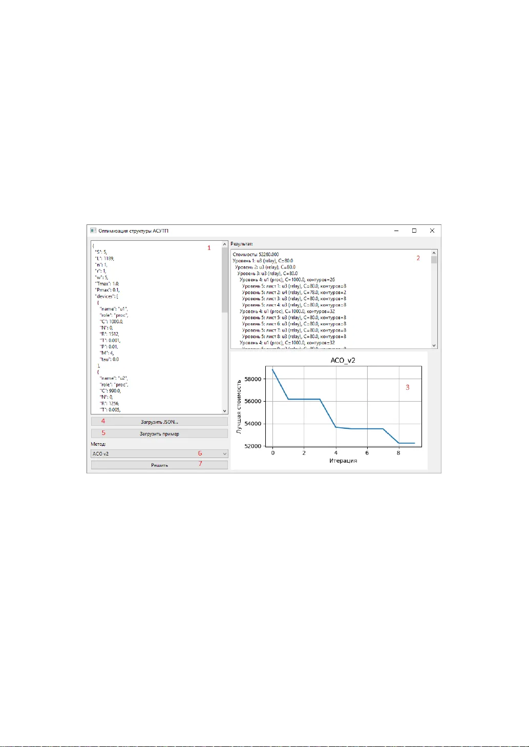
This manus cript is an English translation of a Russian-language article accepted for publication in: Vestnik of Samara State Technical University. Technical Sciences (2026). The original v ersion is the version of record. This translat ion is provided for dissemination pu rposes. The final p ublishe d version will be available in the journal. If citing this work, please cite the original publis hed version. BIO-INSPIRED MET AHEUR ISTIC OPTIMIZ ATION FOR HIERARCHICAL ARCHITECTU RE DESIG N OF INDUSTRIAL CONTROL SYSTE MS R.M. Zakirzyanov 1 1 NEXT Engine ering, LL C 62, Sibgata K hakima st ., K azan, 421001, Russian Fe deration Abstract. Automated proce ss control systems (APCS) are w idely used in mo dern industrial enterprises. They address three key objectives: ensuring the required quality of manufactu red products, ensuring process safety for people and the environment, and reducing capita l and operating costs. A t la rge industrial enterprises, APCSs are typically geographically distributed and ch aracterized by a large number of mo nitored para meters. Such systems often consist of several subsystems bui lt u sing various technical means and serving different functional purposes. APCSs usually have a hierarchical structure consisting of several levels, where each level hosts commerci ally a vailable technical devices with predetermin ed ch aracteristics. This a rticle examines the engineering problem of selecting an optimal software and hardware structure for a d istributed process control system applied to a continuous process in the ch emical industry. A formal formulation of the optimization p roblem is presented , in which the h ierarchical structure of the system is represented as a n acyclic graph. Optimization crit eria a nd constraints are defined. A solution metho d based on a metaheuristic an t colony optimization alg orithm, widely used for this class of problems, is proposed. A brief overview of the developed software tool used to solve a number of numerical examp les is provided . The experimen tal results are discussed, along with para meter selection and possible algorithm mo difications aimed at improving solution quality. Informa tion on the verification of the control system implemented using the selected software and hardware structure is presented, and directions for further research are o utlined. Keywords: distributed con trol system, structu ral optimization, hie rarch ical structure, metaheuristic algo rithm, automated pro cess control system. Introduction Modern industrial processe s are characterized by a high level of aut omation. I n the chemical, petrochem ical, and oil refining industries, production is typically carried out in a n autom atic o r autom ated m ode, w here the proc ess oper ator does not directly control the process but instead perform s supervisory functions and issues control actions in accordance with technologi cal regulations. At such enterprises, the automated process control system (APCS) is implemented as a hardware-software system composed of commercially availab le components [1]. If the co ntrolled object is geog raphically di stributed and involves a large number of variables, the cor responding contro l system is re ferred to as a dis tributed cont rol s ystem (DCS) [2]. The properties and functionality of distributed control systems are largely determined by the system architecture, since the characteristics of the components are predefined by m anufacturers and canno t be modified. Therefore, achiev ing the requir ed system perfor mance necessitates constructing a configuration of components with known characteri stics that m inimizes cost while satisf ying all specified requirements and constraints, i.e., a n optimal arch itecture [3]. 2 The APCS archi tecture is hier archical (Fig. 1) and con sists of multiple levels. The number of levels is determ ined by system designers b ased on the scale, distribution, and f unction al requirements of the system. T raditionally, three f uncti onal levels of an APC S a re di stinguished (lower, m iddle, and upp er) [4]. Howev er, in practical implementations, each functional level may consist of several physical layers [5]. For example, the middle level of a l ocal control system may be implemente d as a single physical layer based on a programmable l ogic controller (PLC), whereas the middle level of a APCS m a y include three or m ore physical layers (input /output modules, contro l units, netw ork switches, etc. ). Fig . 1. T ypical architecture of an AP CS: CPU – control units (programmable controllers), I/O – input/output modules, OS – operator workstations, LCU – local control units. In practice, the hardware configuration of an automated process control system (APCS) i s d etermined at an early stage of system design (often before a m athematical model of th e controll ed obj ect i s avai lable) based on initial informatio n about the sy stem (number of signals, reliabil ity, accuracy, and performance requirem ents). T he selected hardware configuratio n and its characteristics must subsequen tly be taken into account when developing the mathem at ical model of the sy stem . At this stage, t he designer must select system components and cons truct an architecture that ensures effective control of the object during subsequent implem entation, while satisfy ing reliability and performance requirements and minim izing cost. Designing an optimal hardware ar chitec ture for an APC S is an im portant task that is currently addressed pr imarily em pirically, based on the desig ner’s experience and recomm endations from equipment manufacturers. This pa per presents a form al formulation of the proble m of optimizing the hardware architecture of an APC S, proposes a solution method based on the ant colony optimization (ACO) metaheuristic, and outlines direc tions for f urther research i n this area. 3 Related work The problem of optim izing the architecture of techn ical systems rem ains highly relevant and continues to attract significant researc h attention. Various aspec ts of structural optim ization hav e been addressed in the literature. For example, the optimization of robotic assembly systems is st udied in [6], while the construction of optimal architectures for distributed control systems is considered i n [7, 8]. Related problems include the optim ization of production line structures [9], topolog y design [10], and chem ical process system opt imizatio n [11]. The selection of optimal architectures for autom ated process control systems is discussed in [12], whe reas the synthesis of complex sy stem architectures is ad dressed in [13]. M ethods and algori thms for optim izing hierarchical architectures a re comprehe nsively rev iewed in [14, 15]. A wide range of solution m ethods, both exact and appr oximate, has been developed for such optim ization problems. Exact m ethods ar e typically computationally expensive, which limits t heir applicability to large- scale instances. In contr ast, approxim ate methods do not guarantee optimality but can provide near -optim al solutions with moderate com putational eff ort. Metaheuristic algorithms i nspired by biological behavi or (bio-inspired algorithms) or natura l and social phenomena have become widely used for solving bot h continuous and di screte optimization problem s [16]. A large number of such algorithms have been proposed, including the Genetic Algorithm (GA), Tabu Search (TS), Bat Algorithm (BA), Artificial Bee Colony (ABC), Grey Wolf Optimizer (GWO), Ant Colony Optimization (ACO), Particle Sw arm Optimiz ation (PSO ), Cuckoo Search (CS), and Simulated Annea ling (SA) [17]. Metaheuristic algorithm s can be broadly classifi ed into two cat egories: local search methods, whi ch itera tively im prove a single solution (e.g., TS, SA), an d popul ation - based methods. The latter include evolutionary algorithms (e.g., GA) and swarm intelligence algorithms (e.g., A CO, PSO, GWO) [18]. A detaile d ov erview of the historical developm ent of m etaheuristics is provide d in [19]. Metaheuristics have been successfully applied to a wide range of engine ering problems [20]. Standard benchmark pr oblems, such as Tension/Com pression Spring Design (TCSD), P ressure Vessel Desig n (PVD), and Welded Be am D esign (WBD), are commonly used to evaluate optimization algorithms, along wit h classical test functions such as Rosenbro ck, Rastrig in, and Ackley func tions [21]. The Ant Colony Optimization (ACO) algorithm was f irst proposed by M. Dorigo for solving the T raveling Salesman Problem (TSP) in 1992 [22]. Num erous modifications and extensions of ACO have since been developed [23]. Its applications include controller tuning in control systems [24], route optim ization [25], resource planning [26], and facility location p roblems [27] . Recent research has also f ocused on hybrid approaches that combine different metaheuristic algorithm s [28], as well as the integra tion of swarm -based methods with local search techniques [29]. In addi tion, t here is growing i nterest in combining metaheuristics with machin e learning methods [30]. S ev eral studies address the problem of parameter selection and tuning f or metaheurist ic algorithms [31], while othe rs explore automated des ign of proble m-specific evolut ionary algorithm s [32]. The speci fic problem addre ssed in this p aper was origi nally formulated in [33], and the corresponding optimization criteria for distribu ted control system architectures are presented in [34]. 4 Problem Statemen t To form ulate the probl em of finding the o ptim al hardware arch itecture o f an automated process control system (APCS), the system is represen ted as a tree (i.e., an acyclic graph), an exam ple of which is shown in Fig. 2. T he structure illustrated in the figure may represent, for example, the hardwa re architecture of the midd le functional level of an APCS, w hich in turn consists of t hree physical layers. At Level 3 (the lowest lev el in t he fig ure), inpu t/output m odules are located, to which field devices are directly connected. Level 2 contains controllers that implem ent the control logic of the process. Level 1 consists of network switches that interconnect multiple controllers into a unified system . T he number of levels in the architecture may vary. Fig . 2 . Hierarchical architectu re of an APCS Let the hier archical architec ture o f an autom ated pro cess con trol system (APCS) be represented as a graph , wh ere denotes a devic e (grap h node), and is the set of edg es representing communication c hannels betwee n devices. Let be the set of dev ice types. It is assumed that each node of the architecture (i.e., each device), regardless of its type, operates a ccording to a cy clic process con sisting of th e following th ree phases: acquisition of in formation (read ing) from the controlled process or from nodes of the lower hierarchica l level; processing of info rmation (execu tion of contro l algorit hms); transmission of information (writing ) to a lower hier archical level or generation of co ntrol actions app lied to the pro cess. Each device in the system is as signed one of two roles: a processing unit or a relay unit. A processing unit executes control algorithm s (e.g., controllers or servers), whereas a relay unit performs only data transmission functions (e.g., network switches or input/output m odules). Each device type is characterized by th e following parameters: – device cost; – number of physi cal chan nels; – maxim um mem ory capacity; – device failu re probability ; – execution tim e of a single ins truction (perfo rmance); – operating m ode (1 – processing unit, 2 – relay unit); – maxim um number of child devic es; 5 – transmission de lay for relay unit s (for proces sing units ). Each device type is represented by th e vector defin ed in (1). . (1) Let be the set of contro l loops, where eac h loop is de fined as : , (2) where is the number of physical signal s in the loop, is the memory required to store all i nstruc tions and variables of the loop, and is the num ber of instructions in the loop processing pr ogram , characterizing its computational complexity. In general, a loop m ay contain different types o f signals (analog, discrete, input, output, etc.). In thi s study, i t is assumed that all field signals are pre -assigned to loops, and that for each loop t he num ber of signals , the number of instructions in the processing program, and the required memory ar e known (or estim ated). It is further assumed t hat the execution tim e of any instruct ion is constan t and equal to . The optimal cont rol system architecture is repre sented as a tree with levels, where corresponds t o t he root (top of the hiera rchy), and co rresponds to t he leaf level (bottom of the hierarchy ). Let denote the num ber of devices at level , and let be the total number of d evices in the sy stem. Let denote the number of leaf nodes (devices directly connected to field equipment), and let denote the set of leaf nod es. Then, . Based on the above, for each device , the following mappings are introduced: – device ty pe; – parent node; – set of child nodes; – subtree rooted at node , where ; – set of nodes on the path from to the root, includ ing the root. Here, denot es the hierarchy level, and i s the index of the node at level . Thus, each device can be repres ented as the v ector defined in (3). . (3) To solve the pr oblem , it is assumed that only devices at level (le af nodes) are directly conne cted to fie ld equipm ent of the pr ocess plant, i.e., they receive measurem ents from the process and apply con trol actions. It is f urther assumed that all devic es belong to a prede fined set of types and diffe r only in the values of the param eters i ntroduce d above. Horizontal connections betw een devices are not allowed. Each control loop must be physically connected to a leaf node of the tree. A leaf node can process the assig ned loops directly if it is a processing unit ( ), or forward them to an upper-level processing unit if it is a relay unit ( ). Each loop must be assigned to exactly one proce ssing unit. A proc essing unit can p rocess only those loops that are conne cted to leaf nod es within its s ubtree. 6 It is assumed t hat only r elay units introduce transmission delays. Processing units execute assig ned loops cycl ically. T he execut ion ti me of a processing unit is equal to the total processing time of all loops assigned to i t. To simplify the no tation, indice s , , and are omitted below. , where , if control loop is physically connect ed to leaf ( ), and ot herwise; , where , if control loop is assigned to process ing unit ( ), and ot herwise. Thus, if a control l oop is phy sically connected to a node at level , it is considered to be connected to a leaf node (i.e., ) . If the signals of loop are processed at node , then loop is assigne d to node ( i.e., ). The following constraints define t he t ree structure of the di stributed control system. The tree has a single root (4). The root node m ay be either a processing unit or a relay unit. . (4) Nodes located at level (leaf nodes) do not hav e child n odes: . (5) Each node can hav e at m ost child devices: (6) where denotes the type of node . Constrain t (6) applies t o all nodes except leaves. Each control loop m ust be connec ted to exac tly one leaf nod e: . (7) The following constra ints define the assignm ent of control loops to processing units. Only processing units can p rocess control loops; there fore, a loop can not be assig ned to a relay unit: . (8) Each control loop m ust be assig ned to exactly one process ing unit: . (9) Each processing unit is subject to a memory constraint. The total memory required by all assigned loops must not excee d the avai lable mem ory: . (10) A pr ocessing unit can process only those loops that are connected to leaf nodes within its subtre e. Thus, a proce ssing unit serv es only its own s ubtree: . ( 11 ) The t otal number of signals from all control loops connected to a leaf node must not exceed the num ber of a vailable channe ls: . (12) 7 Here, denotes the number of channels determ ined by the device type of node . A node may have . Since the designed ar chite cture corresponds to a control system for a dynamic process, it is im portant to take into account its dynamic properties during synthesis. In practice, this is a c omplex p roblem [13]. As a perform ance indicato r, the maximum processing ti me of a control l oop is considered. For any loop , the total process ing time must not exceed a specified limit . The proces sing time of a control l oop consists of two com ponent s: (i) the execution time of all instructions corresponding to loops assigned to the processing unit, and (ii) the total transmission delay introduced by relay uni ts along the path from the leaf node to the processing unit and back (13). , ( 13 ) wh ere, denotes the proces sing unit a ssigned to control loop , and denotes the path from the leaf node t o which loop is connected to the processing unit . The term is an indicator function e qual to 1 if node i s a relay unit and 0 if it is a proce ssing unit. When designing the system, reliability must be taken into account. The probability of failure is used as a reliability indicator. It is ass umed that the system becom es inoperable if at least one of it s components f ails, and that failures of individual devices are independent. Under these assum pt ions, the system failure probab ility is g iven by . (14) where is the failure p robability determined by th e type of dev ice . In this study, the f ailure probabili ty is assumed to be constant. In real systems, it is generally time-dependent, i.e., [36]. Methods for r eliabili ty evaluation of hierarchical autom at ed process cont rol system s are described in [35, 36]. The follow ing cons traints d efine t he coord ination of pr ocessing uni ts. A proc essing unit cannot hav e a parent that is a lso a proces sing unit: . (15) A processing unit canno t hav e other processing units in its sub tree: . (16) There must be exactly one pr ocessing uni t on the path from any leaf node to the root: , (17) Previously, key criteria for opt imizing the hierarchical architecture of a di stribu ted control system were identif ied in [34]. The total cost is a primary factor in system design. In gene ral, system cost consists of capital and operating costs. Assum ing that t he cost of ea ch device is fixed, the total implem entation cost is defi ned as the sum of the costs of all devices. The op timal hierarchical architecture is obtained by m inimizing the total system cost under const raints (4)-(17): 8 , (1 8) where is the optim al total cost o f the system . Thus, t he structural optim ization problem can be formulated as follows: determ ine a hierarchical architecture composed of devices of predefined t ypes t hat minim izes the objective functio n (18) sub ject to constrain ts (4)-(17). It i s assumed that an unlim ite d number of devices of ea ch t ype is available. The resulting ar chitec ture is assum ed to be a homog eneous tree, i.e., t he path from any leaf node to the root c ontains the sam e number of lev els. Method Selection and Soft ware Implement ation The pr oblem described above is a com bi natorial (discrete) optimization pr oblem with multiple constrain ts. This problem is NP -hard bec ause, under certain assumpt ions, it can be reduced to a known N P-complete problem (e.g., the k napsack problem [37]). Exact methods (e.g., dynamic pr ogramm ing [6]) or approximate methods (e.g., metaheuristic algorithm s) can be u sed to solve the problem. Exact methods are computationally expensive and difficult to scale, and therefore may be ineffective for large problem instances. Therefore, heuristic and metaheuristic algorithms are widely used to solve such problems. Selecting a suitable metaheuristic algorithm is a n ontrivial task in itself [38]. To select an appropriate solution method, an ana lysis of the pe rform ance of common optimization algorithms on t ypical problems (benchmarks) was conducted [17, 21]. In [17], it was shown that the GWO, BA, and CS algorithms perform best when solving continuous optim ization problem s, while GA, ABC, and ACO are m ore suitable for solving discrete p roblems. The genetic algorithm (GA) is designed fo r systems with a fixed struc ture; therefore , when applied to a tree construction problem, difficulties may arise in encod ing solutions. The artificial bee colony algorithm (ABC) does not store in termediate resu lts a nd is not designed for working with tree structures. The ant colony opti miz ation (ACO) algorithm stores int ermediate results, al lows for convenient e ncoding of solutions, as it was originally developed for solving graph problems, is simple to i mplem ent, an d can be easily combined with other algorithms. Therefore, it wa s chosen for so lving the pro blem of optimizing the structure of an automated pro cess contro l system . A description of the ant colony algorithm is given in [22, 37]. A distinctive feature of the algorithm is that it stores the best solutions using traces ( pherom ones ) that evaporate at a cer tain rate. Each step is selec ted accord ing to the follow ing rule: , (19) where is th e probability of se lecting the i -th option, is t he pheromone level associated with the i -th opt ion, is the heuristic value characterizing the cost (preference) of the i -th option, is the p aramete r controlling the influence of pheromone ( “ herding ” ), is the parameter controlling the influence of the heuristic ( “ greed ” ), and is the total number of feas ible options. The pherom one level is upd ated according to the follo wing rule: , (20) 9 where is the ph eromone level at iteration , is the pheromone level at iteration i , i s the pheromone evaporation coefficient, and i s t he amount of deposited pheromone. In this problem , each selection o f a new device to be added to th e tree is performed with a probabil ity determined by expression (19). The ant i ncrem entally constructs the tree f rom the root to the leav es by addi ng graph nodes. T he construction process is completed w hen a feas ible tree is obtained. A fter construction, all const raints ar e verified. If the constructed tree satisfies all constraints, it is considered a v alid solution ; otherwise, i t is discarded. In si mplified f orm , the algorithm consists of several m ain steps, described below. Each selection of a new device is performed by the ACO algorithm according to the rules defined by expressions (19) and (20). The flow chart of the algorithm is shown in F ig. 3. The steps in wh ich the ACO algorithm selects a new dev ice are highlig hted in color. Fig. 3. Flowchart of the al gorithm for constructing the op timal hardware architecture Stage 1. Con struct a tree backbone of he ight , with the process unit leve l defining . Select an arbitr ary device ( either a proce ssing unit or a relay uni t) and place i t at the top level of the hier archy. If the root is a processing unit, only relay unit s can be adde d as its children, since there must be exactly one processi ng unit on any path from a leaf to the root. If the root is a relay unit, bo th processing units and relay uni ts can be added a s its children. Select the next device a nd pla ce it at the next lower level of the hierarchy . I f a processing unit has already been placed above, only a r elay unit can be selected. I f no 10 processing unit has yet been placed i n the backbone, either a processing unit or a relay unit can be sele cted. Repeat this procedu re until level (the leaf l evel) i s reached. At the l eaf lev el, only devices that support connection o f field signals (control loops) c an be us ed, i.e., dev ices with . The level at which t he first proces sing unit is placed is def ined as the processing unit lev el. All s ubsequent process ing units can be placed only at this le vel. Stage 2. Connectin g Control Loops by Adding Leaves and Branches . We begin by connecting control loops to the leaf nodes (initially, there is on ly one leaf). The f irst control loop is selected and connected to t he leaf. Each loop requ ires a certain amount of memory, , for processing. We traverse the tree upward until a pro cessing unit i s found. This process ing unit is assigned to proc ess the loop. We then check whether t he se lected processing unit can process the loop. The available memory of the processing unit must be greater than or equal t o the total memory required by all loops assigned to it. If there is insuffic ient mem or y, the processing unit is r eplaced with another one, and the check i s repeated. If no suitable processing unit can be foun d, the solution does no t exist. If the processing unit has suf ficient memory, t he processing t ime constraint is verified. The sum of transmission delays i ntroduced by all relay units along the path from the leaf node (to which the loop is connected) to t he assigned process ing unit and back, plus the p rocessing tim e of all loops assigned to thi s processing unit, must no t exceed the speci fied value . If ther e are s till available channels on th e leaf node, the nex t control loop is connected using a greedy assignment strategy [39]. I f no channels are av ailable, it is checked whether an additional device can be added at this level of t he hi erarchy . If the parent node allows adding another child dev ice, a new device is sele cted and added at the leaf level. If no addit ional child device can be added (i .e., the maximum number of child devices has been reached), higher levels of the hierarchy are examined. At each lev el, it is ch ecked whether a new child device can be added. Whe n s uch a possibility exists, a new device is sel ected and added to the hie rarchy. If the new device is added a t the leaf level, the connect ion of control loops continues . If the device is added at a higher level, the corresponding branch is extended to the leaf level. If it is not possib le to extend the branch to the leaf level (e.g., due t o selecting a device that does not suppo rt child connec tions), the algorithm bac ktracks t o the upper level and chang es the device ty pe until a feas ible optio n is found. If channel s are availabl e on a leaf node, a control loop i s connected, feasibility is verified, and the l oop is assigned to a processing uni t. The procedure continues until all control loops are connected and assigned to processing units. Stage 3. Con straint Checking . O nce all control loo ps a re connected and a ssigned t o processing units, the system reliability is ev aluated using fo rmula (14). If the s ystem failure probability exceeds the specified value , the solution is discarded. It should be noted that constrain ts (4)-(13) and (15)-(17) are satisfied by construction and do not require additiona l verification. Stage 4. Objective Function Calculation . The system cost objective function is evaluated using formula (18). The cost is defined as the sum of the costs of all system components (i.e., all devices in the hierarchy). The g oal of the a lgorithm is t o find a fe asible tre e with minim al cost. 11 After constructing a feasible solution, the pherom one values are updated acco rding to formula (20), and the next ant is initialized. The number of ants i n the population i s one of the key tuning param eters of the ACO algorith m. The algorithm is exe cuted over multiple iterations. At each iteration, th e best feasible solution is retained. The number of iterations is also config urable. To implem ent the algorithm, a Python program [40] was developed, capable of solving numerical problems of rela tively larg e scale. The softwa re genera tes a tree structure that satisfies the problem constraints. Its functionality allows for the integration of additional solution methods (through the implem entation of corresponding modules), v isualiz ation of the re sulting system architecture, and gene ration of convergence plots. The converg ence plot can be exported in *.png or *.csv format. The m ain interface of the prog ram is shown in Fig . 4. Fig. 4. Main windo w interface of the software: 1 – input field for problem data in JSON format; 2 – output field display ing the resulting system architecture as a tree; 3 – convergence plot of the algorithm; 4 – button for loading input data from a JSON file; 5 – button for loading a default exam ple of input da ta; 6 – dropdown list for selecting the solution method; 7 – button for running the algorithm. The program accepts the following input data i n JSON format: the number of hierarchy levels, the number and types of control loops, constraint li mit s, a descript ion of available dev ice types (process ing units and relay units), and al gorithm parameters ( , , , etc.). The program runs on Window s and Linux o perating system s. Experimental Re sults Using the dev eloped software, a number of numerical examples were s olved, and the influence of algorithm parameters on the solution search process was studied. Testing was performed on a workstation with the following specification s: Intel Core i5 -7400 CPU (3.0 GHz ), 16 GB RAM, 512 GB SSD, and W indows 10 Pro ope rating sy stem. The i nput data f or the numerical example are presented in Table 1. The example considers a set of \( A \) identical control loops with parameters 12 . The maximum processing time of a control loop, s, and the maxim um allowable system failure pr obability, , were used as c onstraints. Table 1 Input data for the numerical exam ple Device type Cost , arb. units 1 000 990 80 78 65 Number of channels , units 0 0 8 4 2 Memory capacity , units 5 12 256 - - - Failure probabilit y 0,01 0,02 0,005 0,005 0,001 Instruction execution time , s 0,002 0,004 - - - Processing unit flag 1 1 0 0 0 Max. number of child nodes , units 4 4 4 4 8 Transmission dela y , s 0 0 0,01 0,03 0,02 Processing units and may represent, for exa mple , programmable logic controllers (PLCs), which are relatively expensive but do not include I/O channels. Relay units , , and may represent I / O modules, to which 2 to 8 physica l signals can be connected, or network switches. All device types are equipped with network ports (4 to 8) for connecting downstre am dev ices. The a lgorithm w as exec uted with a population of 20 ants and 20 iterations. The following ACO parameters were used: , , . For each set of input data, 20 independent runs of th e a lgorithm were performed. The results obtained for different values of and are summarized in Table 2 . The follow ing nota tion is used in Table 2: is the n um ber of con trol loops, is the number of hierarchy levels, i s the best value of the objective function, i s the average value of the objective function, is the coefficient of variation, is the percent age of succ essful run s, an d is the average executio n tim e of the algorithm . Table 2 Experimental Results , units , units , arb . units. , arb . units. , % , % , s 1 3 1120 1120,00 0,00 100 0,013 5 3 1135 1135,00 0,00 100 0,019 10 3 1200 1201,15 0,29 100 0,032 15 3 1215 1215,00 0,00 100 0,040 20 3 1293 1293,20 0,05 100 0,045 25 3 1360 1362,80 0,36 100 0,062 30 3 1375 1375,00 0,00 100 0,061 35 3 1453 1454,20 0,15 100 0,082 40 3 1455 1456 ,00 0, 21 100 0,081 45 3 1535 1540,50 1,27 100 0,092 50 3 1675 1688,25 0,42 100 0,102 55 3 1690 1690,00 0,00 100 0,109 60 3 1768 1770,90 0,27 100 0,136 65 3 1835 1846,55 0,27 100 0,132 70 3 1850 1850,00 0,00 100 0,140 75 3 1928 1929,20 0,05 100 0,169 80 3 1930 1932,05 0,25 100 0,161 13 , units , units , arb . units. , arb . units. , % , % , s 85 3 2010 2027,20 1,70 100 0,171 90 3 2075 2095,15 1,19 100 0,180 95 3 2183 2185,70 0,19 100 0,216 100 3 5065 5079,10 0,21 100 0,201 120 3 5225 5244,90 0,15 100 0,215 140 3 6465 6486,90 0,17 100 0,224 160 3 6635 6731,57 4,39 70 0,224 180 3 - - - 0 - 180 4 4741 5492,00 19,73 100 0,349 200 4 6235 8141,65 14,97 100 0,340 250 4 7391 10420,90 9,53 100 0,370 300 4 13221 13243,45 0,11 100 0,433 350 4 14700 14784,85 0,26 100 0,517 400 4 17249 17288,25 0,11 100 0,545 450 4 19816 19883,05 0,19 100 0,589 500 4 21273 21363,15 0,18 100 0,650 600 4 25330 25591,20 1,75 100 0,666 700 4 29350 30283,67 4,43 30 0,717 800 4 - - - 0 - 800 5 33570 33660,65 0,14 100 0,877 900 5 38735 38782,15 0,07 100 1,010 1000 5 42706 42787,70 0,12 100 1,160 1500 5 63135 63213,70 0,08 100 2,067 2000 5 84439 84557,40 0,06 100 2,977 2500 5 105764 108980,50 6,33 100 3,615 3000 5 126409 148825,60 12,75 25 3,851 5000 5 - - - 0,00 - 5000 6 210896 212027,65 1,19 100 8,534 10000 6 421875 483879,67 13,26 75 25,328 Overall, the algorithm demonstrates good performance. It is noteworthy that for and , the algorithm fails to find feasible solutions, since the given structure does not provide a su fficient number of devices to connect all control loops, and th e constraints prevent the addition of new devices. I n t his case, increasing the number of hierarchy levels is required to ensure connec tivity, as s hown in the tab le. It shoul d also be noted that as the tree approaches its maxim um ca pacity, the solution quality deteriorates significantly. T his is due to t he fact that the feasible solution space becomes highly restricted, and the algorithm is unable to find an initia l feasible solution within the spe cified number of iterations. Possible approaches to address t his issue include increas ing the number of iterations (or the population size) or modifying the algorithm , for example by incorporating local searc h. The convergenc e plots of th e algorithm for selected v alues of and are shown in Fig. 5. The horizontal axis represents the iteration number, and t he vertical axi s represents the ob jective function ( system cost). A graphical representation of the resu lting hierarchical architec tures f or se lected values of and is shown in Fig. 6. T he numbers in the fi gure indicate t he number of connected control loops (for leaf nodes) and assigned control loops (for processing units). Each device type i s represented by a d istinct color (a “warm” color scheme is used for process ing units, and a “c old” color schem e is us ed for relay uni ts). 14 Fig . 5. Converge nce plots of the algorith m for and for Fig . 6 . System architectures for different values of A and S : 1 – and ; 2 – and ; 3 – and Modification and S election o f Algorithm Parame ters The ant colony opti miz ation (ACO) al gorithm is an approximate method and does not guarant ee an e xact s olution t o the problem. How ever, it c an b e used to obtain a baseline solution, wh ich ma y subsequently be improv ed [41]. Like many metaheuristic algorithms, ACO is sensitive to the choice of tuning parameters. The key parameters of the algorithm are the pheromone influence coefficient , the heuristic influence coefficien t , and the pheromone evaporation coefficient . When and , the algorithm reduces to random search. Fig. 7 shows the convergence plots of the a lgorithm for one dataset ( ) from Table 2. The results demonstrate tha t ACO significan tly outperfo rms random search. 15 Fig. 7. Convergence plots o f the algorit hm for different values o f and : 1 – and ; 2 – and ; 3 – and ; 4 – and Numerical experiments show that the problem contains r egions with either too m any or too few feas ible solutions. In such regions, the alg orithm ei ther fails to find a solution within a given number of iterations or conv erges to the optimum very slowly. Sin ce, in these regions, preference should be given to devices with a large number of channels, a promising approach is to modify t he heuristic used in the algorithm (see for mula (19)) to increase the a ttractivenes s of such devices. In pract ice [ 36], the most commonly used heuristic characterizes the cost of a step (in this case, the selected de vice): , (21) where is the cost of the i - th device. To improve the algorithm ’s ability to find feasible solutions, it is proposed to modify the heuristic to fav or low- cost devices with a larg e num ber of channels: , (22) where is the number of channels (i.e., the maximum num ber of connected control loops) of the i - th device. Promising directions for further research include fi ne-tuning of al gorithm parameters and t he developm ent of more complex heuris tics (including adaptive ones) to improv e performance. Furthermore, it should be noted that the ACO algorithm in its pure form is rarely used for solving engineering problem s [23, 29]. T o avoid premature convergence to local optima, it i s ty pically com bined w ith loca l search methods or ot her metaheuristic algorithms (e.g ., GA or ABC). If the i nitial tree is construc ted using ACO, it is re asonable to cons ider applying a genetic alg orithm to further improv e the so lution, since it operates on a fixed stru cture for whic h it is well suite d. 16 Table 3 Input data for the design of the IMS architecture Device type Device model PLC 210 - 01- CS NLSco n-A40- S IGS- 500T IGS- 800T МВ210 - 10 1 NLS- 8AI- Ethernet NLS- 16AI-I- Ethernet Price (including VAT) , RUB 77544 91988 8 968 13285 22977 28182 21350 Number of channels , units 0 0 0 0 8 8 16 Memory capacity , MB 2 56 1024 - - - - - Failure probability 0,0839 0,0839 0,0839 0,0839 0,0839 0,0839 0,0839 AI Instruction execution time , s - - - - - Processing unit flag 1 1 0 0 0 0 0 Max. number of child nodes , units 1 1 5 8 0 0 0 Transmission delay , s 0 0 0 0 0, 6 0,28 0,08 Verification The proposed algorithm was applied to the design of the hardware architecture of the informati on and m easurement system (IMS) for the TGME-428 power boi ler. T he design engineer s were requ ired to develop the hierar chical arch itecture of the IMS at an early stage, g iven incomple te information about th e controlled ob ject. During th e d evelopm ent of the I MS, equipm ent from OWEN (PLC210) [42], RealLab (NLScon PLC) [43], and Pla net (network switches) [44] was con sidered, as presented in Table 3. The parameter values were determined based on the ma nufacturers’ documentation. Prices were obtained from the official websites of the manufacturers as of February 24, 2026. The design was carried ou t for an IMS containing 260 analog sig nals (for each signal: . T he resulting optimal system architecture is shown in Fig. 8. 17 Fig. 8. Hard ware architecture of the IMS for the TGME -428 boiler : – PLC210; – network switch IGS-500T ; – network switch IGS- 800 T ; – analog input module NLS- 16 AI -I-Ethernet The m inimum s ystem cost is 480, 683 RUB. The minimum number of hierarchy levels is . Conclusion The problem of finding an optimal hardware architecture for an automated process control sy stem (APCS) based on com mercially availab le com ponents is hig hly relev ant. At early design stages ( e.g ., feasibility st udies), system developers are required to determine t he system architecture and estimate its cost under conditions of limited information about the controlled object. In practice, such architectures are typically selected empirically, based on the designer’s experience and manufact urers’ recomm endations, and are not g uaranteed to be o ptimal. The results presented in this paper enable t he const ruction of a reference near - optimal APCS architecture under multi ple constraints. This architecture, which defines communication links betwe en components as well as node perform ance and load, should be taken into ac count when dev eloping m athematical m odels of control sy stems. The proposed algorithm can be used by design engineers and APCS developers for the design of large-scale, geographically distributed control systems, where communication de lays, device per formance, and com put ational load are critical factors. Future research directions include: comparison of the proposed ACO-based approach with ot her metaheur istic and exact methods; fine -tuning of algorithm parameters and analysis of their impact on solution quality; development of hybrid approaches c om bining AC O with loca l sea rch and oth er m etaheuristics ( e.g., GA, ABC , GWO) to improv e convergence and avoid local optima; and investigation of mac hine learning techniques for solving the p roblem.I n addi tion, further studies may focus o n t he influence of constraints on the solution process and on refining the formal p roblem formulation by re laxing or r evising the adop ted assum ptions. 18 REFERENCES 1. Kalyvas M. An Innovative Industrial Control System Archit ecture for Real -time Response, Fau lt- tolerant Operation and Seamless P lant Integration // Journal of Engineering, 2021. Vol . 2021. Iss. 10. Pp . 569 – 581. DOI : 10.1049/ tje 2.12064. 2. Denisenko V.V. Komp'yuternoe upravlenie tekhnologicheskim protsessom, eksperimentom, oborudovaniem. Mo nografiya [C om puter Control of Technological P rocesses, Experi ments, Equipment ]. Moscow , Goryachaya liniya - Telekom, 2013. 606 pp . EDN: RBAWTF. (In Russian) 3. Zakirzyanov R.M. A Method For Optim izing The Structure Of The Software A nd Hardware Complex Of A Distrib uted Pro cess Co ntrol Sy stem Fo r Larg e Industrial Enterprises // 18th Internationa l Conference on Management of Large-Scale System Development (M LSD), Moscow, Russian Federation, 2025. P. 1 – 5. DOI : 10.1109/MLSD65526.2025.11220659. 4. Fedorov Y u.N. Sp ravochnik inzhenera po ASUT P. P roektirovanie i razrabotka: Uchebnoe p osobie [Process Control Sy ste ms Engineer's Handbook. De sign and Developm ent: A Study Guide] . Vologda, Infra-Inzheneriya, 2008. 624 pp . (In Russian) 5. Zakirzyanov R.M., Latypov A.R., Shpilev A. I. Opyt importozameshcheniya ASUTP n epreryv nogo proizvodstva v khim icheskoy promyshlenno sti [Experience of Import Sub stitution of Automated Process Control Systems for Continuous Production in the Chemical Industry] // Avtomatizatsiya v promyshlennosti. 2025. No . 12. Pp . 43 – 48. EDN : MWSHQV. (In Russian) 6. Rezchikov A.F., Bol'shakov A.A., Petrov D.Yu., Yakovlev D.D. Algoritm op timizatsii strukt ur robototekhnicheskikh sborochnykh komplek sov [Algorithm for Optimizing the Structures of Robo tic Assembly Complexes] // Avtomatizatsiya v promyshlennosti. 2025. No . 5. Pp . 3 – 10. EDN : XPP IYI. ( In Russian) 7. Onufrey A. Yu., Razumov A.V., Kakaev V.V. Metod opti miza tsii stru ktury v ierarkhicheskikh raspredelennykh siste makh up ravl eniya [Method o f S tructure Op timization in H ierarchical Distributed Control Systems] // Nauchno-tekhnicheskiy v estnik informatsionn ykh tekhnologiy, mekhaniki i optiki. 2023. Vol. 23, no . 1. Pp . 44 – 53. EDN : ELLKBX. (In Russia n) 8. Al Jlibawi A.H.H ., Othman M.L ., Ishak A ., Moh Noor B.S., S ajitt A.H.M.S . Optimization of Distribution Control Sy stem in Oil Refinery by Appl ying Hybrid Machine Learning Techniques // IEEE Access , 2022. V ol . 10, Pp . 3890 – 3903. DOI: 10.1109/ACCESS.2021.3134931. 9. Khrustaleva I.N., Gasyuk D.P., Chernykh L.G., Laptev A.A. V ybor ratsional'noy struktury proizvodstvennoy linii sb orki na osnove im itatsionnogo modelirovaniya [ Selection of a R ational Structure of the Production Ass embly Line Based on Simulation Modeling] // Innovatsionnye idei v mashinostroenii: Sbornik nauchnykh trud ov Vserossiyskoy n auchno -prakticheskoy konferentsii molodykh uchenyk h, Sankt-Peterburg, 24 – 26 m aya 2022 goda. Sankt-Peterburg, POLITEKh-PRESS , 2022. P. 55 – 60. EDN : QHRGUQ. (In Russian) 10. Zh ang Z., Li H., Huang L. The Structural Topology Optimization Based o n Ant Colony Optimization // Yingyong Lixue Xuebao/Chinese Journal of A pplied Mechanics, 2011. Vol. 28. Pp. 226 – 231. 11. S hishkin S.N., Lisitsyn N.V., Kuzichkin N.V. Optimiza tsiya khimiko-tekhnologicheskoy sistem y kombinirovannogo protsessa po lucheniya dizel'nogo top liva [Optimization of the Chemical- Technological System of the Combined Process of Diesel Fuel Production] // Izvestiy a SPbGTI (TU). 2013. No . 18 (44). Pp . 65 – 67. EDN: QAUAJJ. (In Russian) 12. Lu bentsov V.F. , Masyutina G.V., Lubentsova E.V. Sintez struktury ASU TP promyshlennykh proizvodstv [Synthesis o f the Stru cture of Automated P rocess Control S ystem s for Industrial Production] // Sovremennye problemy i puti ikh resheniya v nauke, proizvodstve i obrazovanii . 2018. No. 6. Pp . 9 – 13. EDN: YPUYXA. (In Russian) 13. Tsvirkun A.D. Osnovy sinteza struktury slozhnykh sistem [Fundamentals of Synthesis of the Structure of Complex Systems] . Moscow, Nauka, 1982. 200 pp . (In Russian) 14. Vo ronin A.A., Mishin S .P. Optimal'nye ierarkhicheskie struktury [Optimal Hierarchical Structures] . Moscow, Institut problem upravleniya im. V. A. T rapeznikova RAN , 2003. 214 pp . (In Russian) 15. No vikov D.A., Gubko M.V. Metody optimiza tsii struktury ierarkhicheskikh sistem [Methods for Optimizing the Structure of Hierarchical System s] // Upravlenie raz vitiem krupnomasshtabnykh sistem: Sovremennye problemy. Tom Vypusk 2 . Moscow, Obshchestvo s ogranichennoy otvetst vennost'yu Izdatel'skaya f irma “ Fiziko- matematicheskaya lite ratura” , 2015. Pp . 359 – 377. EDN: YGNUGP. (In Russian) 16. Gla dkov L.A., Kra vchenko Yu .A., Kureychik V.V., Rodzin S.I. Intellektual'nye sistemy: modeli i m etody metaevristicheskoy optimiza tsii [ Intelligent sy ste ms: models and methods o f metaheuristic optimization]. Cheboksary: OOO “ Izdatel'skiy dom “ Sreda ” , 2024. 22 8 pp . EDN: KNHQTN. (In Russian) 19 17. S haban A ., Almufti S., Asaad R. Metaheuristic Algorithms fo r En gineering an d Co mbinatori al Optimization: A Com parative Stu dy Across Problems Ca tegories and Benchmarks // In ternational Journal of Scientific World, 2025. No. 11. Pp. 38 – 49. DOI: 10.14419/0hndc578. 18. Blu m C. , Roli A. Metaheuristics in combinatorial optimization: Overview and conceptual comparison // ACM Computing Surveys (CSUR), 2 001. Vol. 35 . Iss. 3. Pp. 268 – 308. DOI: 10.1145/937503.937505. 19. So rensen K., Sevaux M., Glover F. A History of Metaheuristics // Handbook of Heuristics . Springer, Cham, 2018. Pp. 791 – 808. DOI: 10.1007/978-3-319-07124 -4_4. 20. Ivan ovski T ., Brkic B., Bakaric M., Matetic M. Recent Advances in Metaheuristic Algorithms // Algorithms, 2026. No. 19(1). Pp. 1 – 27. DOI: 10.3390/a19010019. 21. Almu fti S.M. , Asaad R .R., Shaban A.A., Mar qas R.B. Benchm arking metaheuristic algorith ms: a comprehensive review o f test functions, rea l-world problem s, and evaluation metrics // Journal of Electronics, Computer Networking a nd Applied Mathematics , 2025 . No. 5(2). Pp. 16 – 35. DOI: 10.55529/jecnam.52.16.35. 22. Dorig o M., Stutzle T. Ant Colony Optimiza tion. MIT Press, 2004 . 320 pp. 23. Almu fti S.M., Maribojoc R.P., Pahuriray A.V. Ant Based Sy stem: Overview, Modifications and Applications f rom 1992 to 2 022 // P olaris G lobal J ournal o f Scholarly Re search and Trends , 2022. No. 1(1). Pp. 29 – 37. DOI: 10.58429/pgjsrt.v1n1a85. 24. Ab ushawish A ., Ha madeh M., Nassif A . P ID Controller Gains T uning Us ing Metaheu ristic Optimization Methods: A survey // International Journal o f Com puters , 2020. Vol . 1 4, no. 1 4. Pp . 87 – 95. DOI : 10.46300/9108.2020.14.14. 25. Tit ov Yu.P., Sudakov V.A . Primenenie metoda murav'inykh koloniy dlya resheniya parametricheskikh zadach aerokosmicheskoy otrasli [ Application o f the Ant Colo ny Meth od to S olving Parametric Problems in the Aerospace Industry] // Trudy MAI. 2025. No . 142. EDN : UGEDGH. (In Russian) 26. Bu khovtsev D.D. Primenenie algoritma murav'inoy kolo nii dlya resheniya zadachi kalendarnogo planirovaniya [ Application of th e ant colony algorithm to solve th e schedu ling problem] // Sovremennye innovatsii, sistemy i tekhnologii . 2022. Vol. 2 , no . 1. Pp . 22 – 33. EDN : WMJEEF. (In Russian) 27. Pimin ov D .A., Pechenkin V.V., Korolev M.S. Algoritm murav'inoy kolo nii pr i reshenii zadach razmeshcheniya ustroystv bespro vodnykh sete y [ Ant Colony A lgorithm for Solvin g Wireless Network Device Placement Problems] // Nauchno-tekhnicheskiy v estnik Povolzh'ya . 2025. No. 4. Pp . 201 – 204. EDN : CEYHJJ. (In Russian) 28. Bra jevic I. , S tanimirovic P.S., L i S. A Hybrid Firef ly and Multi-Strategy A rtificial Bee Colony Algorithm // International Journal of Com putational Intelligence Systems, 2020. Pp. 810 – 821. DOI: 10.2991/ijcis.d.200612.001. 29. Gamb ardella L.M., Dorigo M. An Ant Colony S ystem Hybridized with a New Local Search for the Sequential Ordering Problem // IN FORMS Jou rnal on Computing, 2000. No. 12(3). P p. 237 – 255. DOI : 10.1287/ijoc.12.3.237.12636. 30. Arık O.A. , T oga G., Atalay B. Reinforcement Learning Based Acceptance Criteria for Metaheuristic Algorithms // International Journa l of C omputational Intelligence Sy stems, 2025. Vol. 18, no. 207. Pp. 1 – 28. DOI : 10.1007/s44196-025-00924- 2. 31. Lo pez- Ib an ez M. , Stutzle T. An Analysis of Alg orithmic Components for Multiobjective Ant Colony Optimization: A Case Study on the Bio bjective TSP // Lecture Notes in Computer Science , Springer, Berlin, Heidelberg , 2010. V ol . 5975. P. 134 – 145. DOI : 10.1007/97 8-3-642-14156-0. 32. Tia n Y., Qi X., Yang S., He C., Tan K.C., Jin Y., Zhang X. A Un iversal Framework for Automatically Generating Single-and Multi-Objective Evolutionary Algorithms // IEEE Transactions on Evolutionary Computation, 2025. DOI: 10.1109/TEVC.2025.3645645. 33. Za kirzyanov R.M. Application o f Metaheuristic Algorithms for Optimizing the Structure of Industrial Control Sy stem // VI In ternational Conference on Control in Technical S ystems (CTS), Saint Petersburg, Russian Federation, 2025. P. 34 – 36 . DOI : 10.1109/CTS67336.2025.11196304. 34. Za kirzyanov R.M . Kriterii vybora optimal'noy struktury raspredelenno y sistemy upravleniya tekhnologicheskimi protsessami krupnyk h promy shlennykh predpriyatiy [ Criteria for Selecting the Optimal Structure o f a Distributed P ro cess Control System for L arge Industrial Enter prises] // Matematicheskie metody v tekhno logiyak h i tekhn ike, 2024. No . 10. P. 17 – 23. EDN : WVOPZN. (In Russian) 35. Akimova G.P., Solov'ev A.V . Metodologiya otsenki nad ezhnosti ierarkhicheskikh informatsionnykh sistem [Methodology for Assessing the Reliability of Hierarchical Informa tion Systems] // Trudy Instituta sistemnogo analiza Rossiyskoy akademii nauk . 2006 . Vol. 23. Pp . 18 – 47. EDN: KBXHKD. (In Russian) 20 36. Ya strebenetskiy M.A. Nadezhnost' avtomatizirovannykh siste m upravleniya tekhnolo gicheskimi protsessami: Ucheb. Posobie dlya vuzov [Reliability of Automated Process Contro l Systems: A Textbook for Universities]. Moscow, Energoatomizdat, 1989. 264 pp . (in Russian) 37. S chiff K. Ant Colony Optimization Algorithm for the 0- 1 Knapsack P roblem // Czasopismo Techniczne, 2014. Pp. 39 – 52 . DOI : 10.4467/2353737XCT.14.056.3964. 38. Meshalkin V.P. , Ratkin I.M., Petukhova E.V . Srav nitel'nyy analiz effektivnosti geneticheskogo i murav'inogo algoritmov p oiska minimal'nogo puti pri opti miza tsii khimiko-tekhno logicheskikh protsessov [Comparative Analysis of the Efficiency o f Genetic and Ant Algorithms for Finding the Minimum Path in Optim izing Chem ical-Technological Processes] // Uspekhi v khim ii i khimicheskoy tekhnologii. 2023. Vol. 37, no. 17(279). Pp . 58 – 60. EDN : NVUQMQ. (In Russian) 39. Zh ang J. The Logic and Appli cation of Gree dy A lgorithms // Applied and C omputational En gineering , 2024. No . 82. Pp . 154 – 160. DOI: 10.54254/2755-2721/82/20241110. 40. P atent 2025665921. Pro gramm a vy bora optimal'noy struktury raspredelennoy siste my u pravleniya [Program for Selecting the Optimal Structu re of a Distributed Control System] / R.M. Zakirzyanov (R ussian Federation). No. 2025664864: stat. 29.05.2025; publ . 20.06.2025. EDN: RCSVNQ. 41. Wan g Y., Chen P ., W u Y., Chen W., Tan L . Modified Continuous Ant Colony Optim ization with L ocal Search for Multiple Unmanned Aerial Vehicle Path Planning // 6th International Conference on Da ta- driven Optimization of Complex Systems (DOCS), Hangzhou, China, 2024. P. 557 – 564. DOI : 10.1109/DOCS63458.2024.10704243. 42. PL K210 vysokoproizvoditel'nyy programmiruemyy kontroller s rasshirennymi setevymi vozmozhnostyami [PLC210 High-Performance P rogrammable Controller with A dvanced Network Capabilities]. URL: https://owen.ru/product/plk210 (accessed February 24 , 2026 ). 43. NLS con-A40-S | Vysokoproizvoditel'nyy promyshlennyy PLK [ NLScon-A40-S | High-P erform ance Industrial P LC]. URL : https://www.realla b.ru/catalog/plc/nlscon -a40-s/ (accessed February 24 , 2026 ). 44. Ko mmutatory promyshlennye neupravlyaemye [Unmanaged Industrial Switches ]. URL : https://shop.planet.com. ru /catalog/kommutatory/kommutatory-promyshlennye/kommutatory- promyshlennye-neupravlyaemye/ (accessed February 24, 2026).
Original Paper
Loading high-quality paper...
Comments & Academic Discussion
Loading comments...
Leave a Comment