A Baseline Mobility-Aware IRS-Assisted Uplink Framework With Energy-Detection-Based Channel Allocation
This paper develops a self-contained framework for studying a mobility-aware intelligent reflecting surface (IRS)-assisted multi-node uplink under simplified but explicit modeling assumptions. The considered system combines direct and IRS-assisted na…
Authors: Ardavan Rahimian
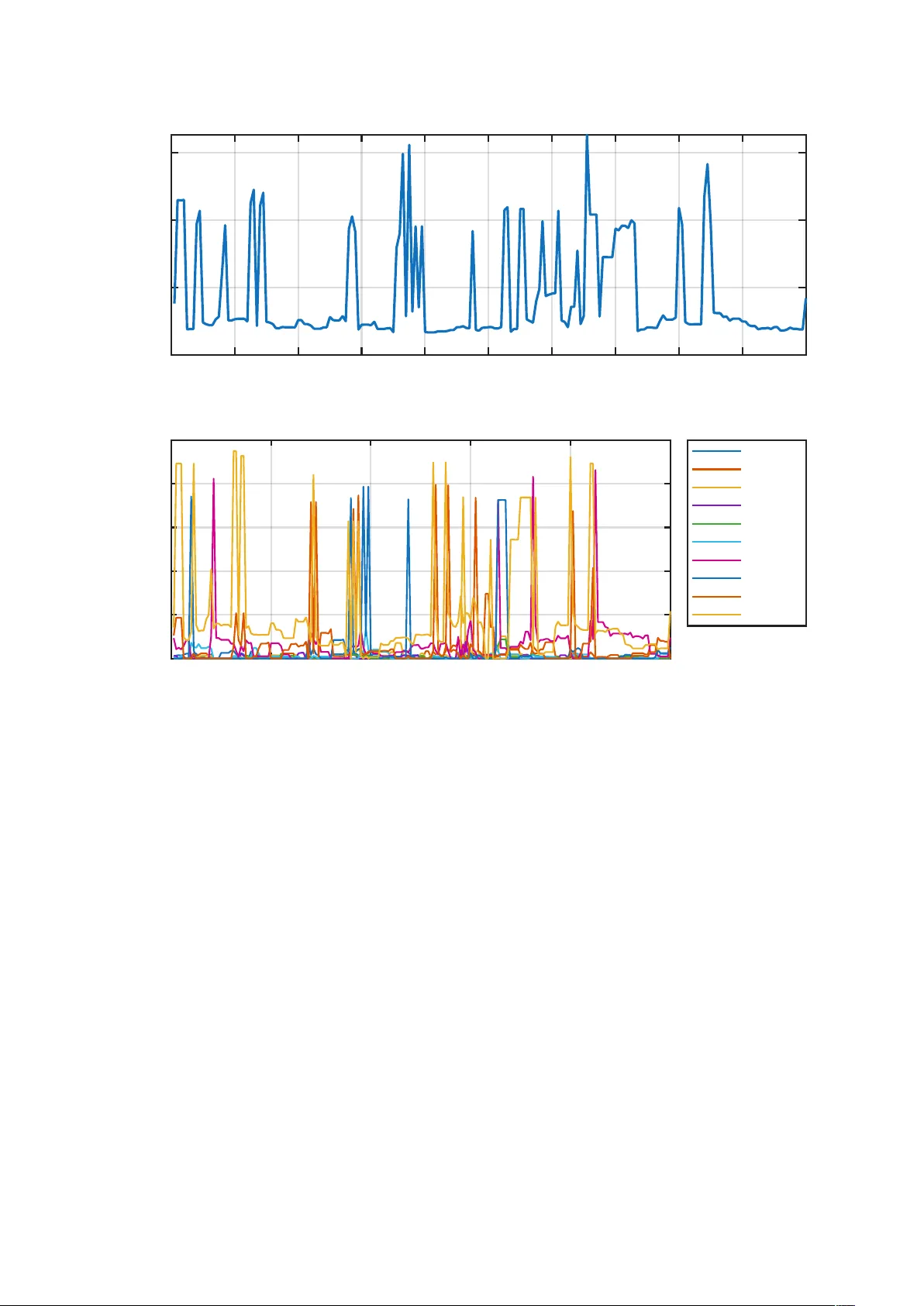
A Baseline Mobilit y-A w are IRS-Assisted Uplink F ramew ork With Energy-Detection-Based Channel Allo cation Arda v an Rahimian Sc ho ol of Engineering, Ulster Universit y , Belfast, U.K. a.rahimian@ulster.ac.uk Abstract This pap er dev elops a self-con tained framework for studying a mobilit y-aw are in telligent reflecting surface (IRS)-assisted m ulti-no de uplink under simplified but explicit modeling as- sumptions. The considered system com bines direct and IRS-assisted narrowband propagation, geometric IRS phase con trol with finite-bit phase quan tization, adaptiv e IRS-user fo cusing based on in verse-rate priorit y weigh ts, and sequential channel allo cation guided by energy detection. The analytical developmen t is restricted to a physics-based tw o-hop cascaded path-loss form ulation with appropriate scaling, an exp ectation-lev el reflected-p o wer charac- terization under the stated independence assumptions, and the exact chi-square threshold for energy detection, together with its large-sample Gaussian approximation. A MA TLAB implemen tation is used to generate a sample run, which is interpreted as a numerical example. This w ork is intended as a consisten t, practically-aligned baseline to supp ort future extensions in volving richer mobility mo dels or more adv anced scheduling p olicies. Keyw ords: adaptiv e sc heduling, energy detection, in telligen t reflecting surface, mobility-a w are uplink, sequen tial channel allo cation, wireless propagation. 1 In tro duction In telligent reflecting surfaces (IRSs) or programmable metasurfaces provide adv anced mec hanisms and methods for shaping radio propagation by adjusting the phases of man y reflecting elemen ts [ 1 , 2 , 3 , 4 , 5 ]. Related studies ha ve also examined ph ysics-based path-loss mo deling, mobility- orien ted IRS b eha vior, and comparisons with other rela ying paradigms [ 7 , 6 , 8 ]. In m ulti-user uplinks, IRS con trol in teracts with user prioritization, interference, and c hannel access. Under mobilit y , ev en a simplified mo del must trac k changing geometry , time-v arying fading, and p er-slot sc heduling c hoices, as well as the asso ciated factors in suc h distributed netw orks. The purpose of this work is to be practical and to serv e as a baseline implementation of suc h subsystems for low-pow er wireless net works or In ternet of Things (IoT) scenarios. It establishes a coheren t foundation, retaining only the segmen ts and asso ciated analyses that are most suitable for such use cases. Within this scop e, the framework com bines the following: a narro wband uplink model with direct and IRS-assisted propagation; geometric IRS phase alignmen t with finite-bit quan tization; inv erse-rate priorit y-weigh ted random selection of the IRS fo cus user; and sequen tial channel allo cation driv en b y an exact energy-detection threshold. The key contributions of this prop osed framew ork are as follo ws: it adopts a physics-based t wo- hop IRS path-loss mo del with the correct L 2 0 cascaded scaling [ 7 ]; it states a mean reflected-p ow er prop osition under explicit indep endence assumptions; it derives and uses the exact chi-square threshold for energy detection, together with the standard large-sample Gaussian approximation [ 9 , 10 ]; it formalizes the implemented adaptive IRS-fo cus p olicy and the sensing-guided sequential 1 c hannel-allo cation rule; and it rep orts one seeded n umerical example as an illustrativ e run only , while separating numerical output from theoretical claims. The w ork first form ulates a simplified mobility-a w are IRS-assisted uplink mo del and defines the asso ciated notation and propagation assumptions. It then dev elops the analytical results that are justified within this scope: the direct and cascaded path-loss structure, an expectation-level c haracterization of the reflected p o wer under independent small-scale fading, and the exact energy-detection threshold used for sensing-guided channel allocation. On top of this mo del, the pap er formalizes the implemen ted inv erse-rate adaptive fo cusing rule and the sequen tial c hannel-assignment pro cedure, and finally rep orts a seeded n umerical example generated b y the MA TLAB sim ulator to illustrate the behavior of the framew ork. In this w a y , the paper aims to pro vide a foundational reference that is suitable for subsequen t refinemen t and extension. Notation T able 1: Main notation used in the paper. Sym b ol Meaning K Num b er of uplink no des/users. N = N x N y Num b er of IRS elements, with N x and N y along the t wo array dimensions. u k ( t ) , b , r 0 , r n P osition of no de k , base station (BS), IRS cen ter, and IRS elemen t n , respec- tiv ely . λ , f c , c W av elength, carrier frequency , and sp eed of light. ρ IRS reflection efficiency . h k, d ( t ) , h k, IRS ( t ) , h k ( t ) Direct, IRS-assisted, and total uplink channel of user k . β d ( d ) Large-scale direct-link gain at distance d . β 12 ( d 1 , d 2 ) T wo-hop cascaded large-scale gain for user-to-IRS distance d 1 and IRS-to-BS distance d 2 . ψ n ( t ) IRS phase applied by element n at slot t . v k ( t ) , f D No de velocity and corresp onding Doppler shift. P tx , σ 2 User transmit p ow er and receiver noise p ow er. c k ( t ) , C Channel assigned to user k and total num b er of orthogonal channels. M , P fa , γ Num b er of sensing samples, target false-alarm probability , and energy-detection threshold. R k ( t ) , ¯ R k ( t ) Instan taneous rate and sliding-window av erage rate of user k . W , β , ϵ A veraging-windo w length, priority exp onen t, and small regularization constant in the sc heduler. 2 System Mo del and Channel Characterization Consider an uplink net work with K single-an tenna devices and a single-an tenna BS. The BS is lo cated at b ∈ R 3 . An IRS with N = N x N y reflecting elemen ts is cen tered at r 0 ∈ R 3 and its n th elemen t is at position r n . Device k is at p osition u k ( t ) ∈ R 3 at slot t . Devices mo v e inside a bounded region A ⊂ R 3 with reflectiv e b oundary conditions. 2.1 Comp osite uplink c hannel The complex baseband uplink channel from node k to the BS is mo deled as h k ( t ) = h k, d ( t ) + h k, IRS ( t ) , (1) 2 where h k, d ( t ) is the direct path and h k, IRS ( t ) is the IRS-assisted comp onen t. The direct channel is written as h k, d ( t ) = q β d ( d kb ( t )) ˜ h k, d ( t ) e − j 2 π λ d kb ( t ) , (2) where d kb ( t ) = ∥ b − u k ( t ) ∥ (3) and ˜ h k, d ( t ) ∼ C N (0 , 1) in the sim ulator. The IRS-assisted comp onen t is mo deled as h k, IRS ( t ) = N X n =1 ρ g k → n ( t ) g n → b e j ψ n ( t ) , (4) where ρ ∈ [0 , 1] is the reflection efficiency and ψ n ( t ) is the phase shift of element n . 2.2 T wo-hop cascaded channel mo del The user-to-elemen t and elemen t-to-BS coefficients are mo deled as g k → n ( t ) = q β d ( d kn ( t )) ˜ g k,n ( t ) e − j 2 π λ d kn ( t ) , (5) g n → b = q β d ( d nb ) ˜ g n,b e − j 2 π λ d nb , (6) with d kn ( t ) = ∥ r n − u k ( t ) ∥ , d nb = ∥ b − r n ∥ . (7) The BS and the IRS are fixed, so the elemen t-to-BS link is treated as quasi-static o ver the sim ulated run. Therefore, the cascaded large-scale factor is β 12 ( d kn ( t ) , d nb ) = β d ( d kn ( t )) β d ( d nb ) . (8) Substituting equations (5) and (6) in to equation (4) yields h k, IRS ( t ) = ρ N X n =1 q β 12 ( d kn ( t ) , d nb ) ˜ g k,n ( t ) ˜ g n,b e − j 2 π λ ( d kn ( t )+ d nb ) e j ψ n ( t ) . (9) This is also the form implemen ted in the code b efore summation o v er the IRS elemen ts. 2.3 Ph ysics-based path loss The direct and cascaded large-scale gains are modeled as β d ( d ) = ( 1 , d ≤ d 0 , ( L 0 d α ) − 1 , d > d 0 , (10) β 12 ( d 1 , d 2 ) = ( 1 , d 1 d 2 ≤ d 2 0 , ( L 2 0 d α 1 d α 2 ) − 1 , d 1 d 2 > d 2 0 , (11) where L 0 = 4 π λ 2 , d 0 = λ 2 π , (12) and α is the path-loss exponent. The essential p oin t is the t w o-hop scaling factor L 2 0 , whic h is consisten t with the ph ysics-based cascaded path-loss mo del in [7]. 3 2.4 IRS phase design F or a designated focus user k ⋆ ( t ) , the simulator uses geometric phase alignmen t, ψ geom n ( t ) = wrap [ − π ,π ) 2 π λ d k ⋆ n ( t ) + d nb , (13) whic h comp ensates the deterministic path-length phase term in equation (9). The co de also supp orts an idealized p erfect c hannel state information (CSI)-based phase-design mode, ψ CSI n ( t ) = wrap [ − π ,π ) 2 π λ d k ⋆ n ( t ) + d nb − arg ˜ g k ⋆ ,n ( t ) − arg ˜ g n,b , (14) but the reported run uses geometric control only . After phase design, the applied IRS phases are quantized using b bits. In the rep orted example, b = 3 , so eac h phase is mapped to one of 2 b = 8 uniformly spaced quan tization lev els. Prop osition 1 (Mean reflected-p o wer scaling) . A ssume for a fixe d user k that, for e ach IRS element n , the smal l-sc ale c o efficients ˜ g k,n ( t ) and ˜ g n,b ar e zer o-me an, unit-varianc e, and mutual ly indep endent. A lso, assume that the p airs { ( ˜ g k,n ( t ) , ˜ g n,b ) } N n =1 ar e indep endent acr oss differ ent IRS elements. Then E h | h k, IRS ( t ) | 2 i = ρ 2 N X n =1 β 12 ( d kn ( t ) , d nb ) . (15) Conse quently, if the p er-element lar ge-sc ale factors r emain of c omp ar able or der, the me an r efle cte d p ower sc ales line arly with N , i.e., as O ( N ) . Pr o of. Define X n ( t ) = ˜ g k,n ( t ) ˜ g n,b (16) and a n ( t ) = ρ q β 12 ( d kn ( t ) , d nb ) e − j 2 π λ ( d kn ( t )+ d nb ) e j ψ n ( t ) . (17) Then equation (9) can b e written as h k, IRS ( t ) = N X n =1 a n ( t ) X n ( t ) . (18) Therefore, E h | h k, IRS ( t ) | 2 i = E N X n =1 a n ( t ) X n ( t ) ! N X m =1 a m ( t ) X m ( t ) ! ∗ (19) = N X n =1 N X m =1 a n ( t ) a ∗ m ( t ) E [ X n ( t ) X ∗ m ( t )] . (20) F or n = m , independence across IRS elemen ts and the zero-mean assumptions imply E [ X n ( t ) X ∗ m ( t )] = 0 . (21) F or n = m , E [ | X n ( t ) | 2 ] = E [ | ˜ g k,n ( t ) | 2 ] E [ | ˜ g n,b | 2 ] (22) = 1 . (23) Hence, only the diagonal terms remain, and th us E h | h k, IRS ( t ) | 2 i = N X n =1 | a n ( t ) | 2 = ρ 2 N X n =1 β 12 ( d kn ( t ) , d nb ) , (24) whic h pro ves equation (15). 4 Remark 1. This work do es not claim a deterministic instantane ous Θ( N 2 ) sc aling law for the r efle cte d p ower. Str onger c oher ent-sum sc aling statements would r e quir e additional assumptions and ar e not ne e de d for the pr esent fr amework. 2.5 Simplified mobility and Doppler model The mobility mo del is in tentionally simple. Eac h node is initialized with a random planar heading and a speed no larger than v max . At slot index ℓ , the p osition ev olves according to u k [ ℓ + 1] = u k [ ℓ ] + ∆ t v k [ ℓ ] , (25) follo wed by sp ecular reflection if a b oundary of A is crossed. The small-scale fading ev olution used in the code is hybrid. First, a coherence-time pro xy is formed from the maxim um Doppler shift, f D, max = ∥ v k [ ℓ ] ∥ λ , T coh ≈ 0 . 423 f D, max , (26) with a small low er bound used in the implemen tation to a v oid division b y v ery small v alues. When the elapsed time since the last redra w exceeds this pro xy , the direct-link coefficient and the user-to-IRS co efficien ts asso ciated with that no de are redra wn as fresh circularly symmetric complex Gaussian v ariables, while the IRS-to-BS coefficients are k ept quasi-static o ver the run. This metho d is a ligh tw eight abstraction rather than a full mobilit y model as in other studies [ 6 ]. Bet ween redra ws, phase ev olution is mo deled through a Doppler shift. F or a propagation direction represen ted b y a unit v ector ˆ k , f D = v k [ ℓ ] ⊤ ˆ k λ = ∥ v k [ ℓ ] ∥ λ cos θ , (27) so the phase ev olution of the corresp onding small-scale co efficien t is approximated b y ˜ h ( t + ∆ t ) = ˜ h ( t ) e j 2 π f D ∆ t . (28) This is a simplified mobilit y-aw are fading abstraction, not a full Jakes-t yp e stochastic time- correlation model [11]. 3 SINR Mo del and Energy-Based Channel Allo cation A t eac h slot, ev ery user is assigned one of C orthogonal channels. Users assigned to the same c hannel are mo deled as m utual in terferers in the signal-to-in terference-plus-noise ratio (SINR) calculation. Let c k ( t ) ∈ { 1 , . . . , C } denote the c hannel assigned to user k at slot t , and define the instan taneous receiv ed signal p o wer as P rx k ( t ) = P tx | h k ( t ) | 2 . (29) Then the simulator computes the instantaneous SINR of user k as SINR k ( t ) = P rx k ( t ) P j = k : c j ( t )= c k ( t ) P rx j ( t ) + σ 2 , (30) where σ 2 is the receiver noise pow er. With bandwidth B , the instantaneous rate is R k ( t ) = B log 2 1 + SINR k ( t ) , (31) and in the sim ulator this rate is set to zero whenever SINR k ( t ) < γ dec , lin , where γ dec , lin = 10 γ dec / 10 . (32) F or the rep orted run, γ dec = − 10 dB. 5 3.1 Energy detector and exact threshold F or a candidate c hannel c , the sensing statistic uses M complex samples, T c = M X m =1 | y c [ m ] | 2 . (33) Under the noise-only h yp othesis H 0 , the co de assumes that y c [ m ] ∼ C N (0 , σ 2 ) , m = 1 , . . . , M , (34) and that these samples are indep endent across m . Since 2 | y c [ m ] | 2 /σ 2 ∼ χ 2 2 , summing o ver M samples giv es the standard result below. Theorem 1 (Exact energy-detection threshold) . Under H 0 , assume that y c [ m ] ∼ C N (0 , σ 2 ) , m = 1 , . . . , M , (35) and that the samples ar e indep endent acr oss m . Then 2 σ 2 T c ∼ χ 2 2 M . (36) Ther efor e, for a tar get false-alarm pr ob ability P fa , γ = σ 2 2 F − 1 χ 2 2 M (1 − P fa ) (37) ensur es P ( T c > γ | H 0 ) = P fa . (38) F or lar ge M , the appr oximation γ ≈ σ 2 M + √ M z 1 − P fa (39) is obtaine d fr om the Gaussian appr oximation to the chi-squar e law, wher e z 1 − P fa is the (1 − P fa ) standar d-normal quantile. Pr o of. Under H 0 , each sample satisfies y c [ m ] ∼ C N (0 , σ 2 ) , so its real and imaginary parts are indep enden t N (0 , σ 2 / 2) random v ariables. Hence 2 | y c [ m ] | 2 σ 2 ∼ χ 2 2 . (40) Assuming independence across m , summing ov er M samples yields 2 σ 2 T c = M X m =1 2 | y c [ m ] | 2 σ 2 ∼ χ 2 2 M . (41) The threshold in equation (37) follows by in version of the cumulativ e distribution function of χ 2 2 M . F or large M , the Gaussian appro ximation follo ws from the fact that a c hi-square random v ariable with 2 M degrees of freedom has mean 2 M and v ariance 4 M . A ccordingly , replacing χ 2 2 M b y its normal appro ximation and rescaling b y σ 2 / 2 yields equation (39). 6 3.2 Sequen tial c hannel allocation rule The code forms a running energy estimate for eac h c hannel before assigning users. Let T c, noise ( t ) denote a noise-only energy draw for c hannel c , generated according to the same H 0 mo del. Let c j ( t − 1) denote the c hannel used by user j in the previous slot. Then the initial running energy of c hannel c at slot t is E (0) c ( t ) = T c, noise ( t ) + M X j : c j ( t − 1)= c P rx j ( t ) . (42) The first term mo dels sensing noise, while the second term initializes the channel-energy estimate using the curren t-slot received-pow er v alues of users that occupied c hannel c in the previous slot. Users are then pro cessed sequentially in no de-index order. If user k is currently b eing assigned and E ( k − 1) c ( t ) denotes the running energy of c hannel c after pro cessing users 1 , . . . , k − 1 , the implemen ted assignmen t rule is c k ( t ) = the first c suc h that E ( k − 1) c ( t ) < γ , if suc h a channel exists , arg min 1 ≤ c ≤ C E ( k − 1) c ( t ) , otherwise , (43) follo wed by the update E ( k ) c k ( t ) ( t ) = E ( k − 1) c k ( t ) ( t ) + M P rx k ( t ) . (44) This is a sequen tial energy-guided heuristic that is in ternally consistent but not claimed to b e globally optimal. 4 A daptiv e IRS F o cus Sc heduling The simulator selects one fo cus user p er slot and aligns the IRS phases to that user. The fo cus p olicy is round-robin during an initial w arm-up p erio d, then b ecomes adaptive. 4.1 Sliding-windo w rate and priority w eigh ts Let W ( t ) = { max (1 , t − W + 1) , . . . , t } (45) denote the current a veraging window. The sliding-window av erage rate of user k is ¯ R k ( t ) = 1 |W ( t ) | X τ ∈W ( t ) R k ( τ ) . (46) The priorit y weigh t is then defined as w k ( t ) = 1 ( ¯ R k ( t ) + ϵ ) β , (47) where ϵ > 0 preven ts division b y zero and β ≥ 1 controls how aggressively low-rate users are prioritized. The normalized sampling probabilities are p k ( t ) = w k ( t ) P K j =1 w j ( t ) . (48) 7 Algorithm 1 Co de-matc hed adaptive IRS scheduling and channel allo cation Require: Net work parameters, IRS parameters, window W , exponent β , regularization ϵ , sensing parameters M and P fa , deco de threshold γ dec . 1: Initialize geometry , random seed, no de p ositions, no de velocities, small-scale c hannels, rate histories, a verage-rate v ariables, and previous channel assignments. 2: for t = 1 to T do 3: Up date user kinematics with reflective b oundaries. 4: Up date direct-link and user-to-IRS small-scale c hannels via coherence-time redraws and Doppler phase evolution. 5: if t ≤ W then 6: Select the fo cus user by round robin. 7: else 8: Compute the most recently a v ailable sliding-window av erage rates, then form the w eights and sampling probabilities according to equation (46)–equation (48). 9: Sample the fo cus user according to equation (49). 10: end if 11: Compute the IRS phase profile for the selected fo cus user and quantize it to 2 b lev els. 12: Compute the direct, cascaded, and total channels, and then compute the received p o w ers P rx k ( t ) for all users. 13: Compute the exact energy-detection threshold γ from equation (37). 14: Initialize the running channel energies according to equation (42). 15: for k = 1 to K do 16: Assign c k ( t ) according to equation (43). 17: Up date the corresp onding running channel energy according to equation (44). 18: end for 19: Compute each user SINR via equation (30) and the corresp onding rate via equation (31). 20: Set the rate to zero for users with SINR k ( t ) < γ dec , lin . 21: Up date the sliding-window av erage rates and priority v ariables for use in the next slot. 22: end for 23: Output no de-lev el rates, av erage SINRs, fo cus fractions, and net work-lev el summary metrics. After the warm-up p eriod, the fo cus user for slot t is sampled according to the distribution formed from the most recently av ailable av erage rates, i.e., k ⋆ ( t ) ∼ { p k ( t − 1) } K k =1 , (49) with the understanding that, in implementation, the probabilities are up dated from the rate history accumulated up to the preceding slot. In the rep orted run, W = 20 , β = 2 , and the first W slots use round-robin fo cus assignment. It should also b e noted that the adaptive p olicy is fairness-a ware by construction, since users with low er recen t rates receive higher sampling probabilities. Ho wev er, this work makes no claim of prop ortional-fair conv ergence, optimality , or guaranteed fairness attainment. The scheduler is used here as a light weigh t adaptive mechanism rather than as a theorem-driven control law. 5 Illustrativ e Seeded Numerical Example The simulation parameters used in the co de-generated run are listed in table 2. The run uses fixed seed 42 and spans T = 200 slots, i.e., 1 s with slot duration ∆ t = 5 ms. 8 The MA TLAB co de rep orts av erage SINR in the following exact form: A vgSINR k = 10 log 10 1 T T X t =1 SINR k ( t ) ! . (50) Th us, the a veraging is carried out in the linear domain and con verted to dB afterw ard. This is imp ortan t when comparing av erage SINR and a verage rate, b ecause the rate is thresholded and dep ends on instantaneous channel sharing. T able 2: Simulation parameters for the demonstrative run. P arameter V alue Carrier frequency f c = 3 . 5 GHz ( λ = c/f c ) Num b er of c hannels / bandwidth C = 4 , B = 5 MHz No des / IRS size K = 10 , N = 8 × 8 = 64 Elemen t spacing / quantization λ/ 2 , b = 3 bits (8 levels) Reflection efficiency ρ = 0 . 98 P ath-loss exp onen t α = 2 . 2 T ransmit p o wer / noise figure P tx = 20 dBm, NF = 6 dB Noise pow er σ 2 = k B T 0 B 10 NF / 10 , with T 0 = 290 K and NF = 6 dB Deco de threshold γ dec = − 10 dB Sensing parameters M = 128 , P fa = 0 . 1 (exact χ 2 threshold) Mobilit y / slotting v max = 3 m/s, ∆ t = 5 ms, T = 200 Sc heduler parameters W = 20 , β = 2 ; warm-up: round robin for the first W slots BS / IRS-cen ter p ositions b = [0 , 0 , 10] ⊤ m, r 0 = [30 , 0 , 8] ⊤ m Initialization region / motion A = [ − 50 , 50] × [ − 50 , 50] × [0 , 3] m; random planar heading, sp eed ≤ v max , reflectiv e b oundaries 5.1 P er-no de statistics T able 3 repro duces the p er-no de a verage SINR, av erage rate, and IRS fo cus fraction rep orted b y the co de for the seeded adaptive run. The results should b e interpreted with caution: the sc heduler reallo cates fo cus time to several low er-rate users, but the resulting op erating p oin t remains strongly heterogeneous across the netw ork. T able 3: Per-node statistics for the adaptiv e run. No de A vg SINR A vg Rate IRS F o cus Commen t (dB) (Mbps) (%) 1 − 8 . 78 0 . 68 25 . 0 lo w-rate and heavily prioritized 2 − 0 . 20 1 . 87 8 . 0 mo derate 3 21 . 47 1 . 37 10 . 0 fa vorable SINR but intermitten t throughput 4 − 10 . 79 0 . 35 12 . 5 below the deco de threshold on av erage 5 − 8 . 97 0 . 55 14 . 0 lo w-rate and prioritized 6 − 6 . 38 1 . 08 10 . 5 lo w-to-mo derate 7 32 . 71 6 . 70 1 . 5 strong 8 31 . 50 4 . 24 16 . 5 strong, but still given notable fo cus time 9 30 . 91 5 . 94 1 . 0 strong 10 43 . 43 19 . 69 1 . 0 dominant 9 A verageSINRpernode(adaptivesc heduling) Node 1 2 3 4 5 6 7 8 9 10 A vgSINR[dB] -20 -10 0 10 20 30 40 MinDecodeThre shold IRSBeam Allocation Node 1 2 3 4 5 6 7 8 9 10 IRSFocusT ime(%) 0 5 10 15 20 25 Figure 1: Per-node av erage SINR together with the minimum deco de threshold, as well as the corresp onding IRS fo cus-time allo cation for the seeded adaptiv e run. 5.2 Net w ork-level b eha vior T able 4 summarizes the net work-lev el outcomes of the adaptive run. The rep orted fairness figures are presen ted without optimistic in terpretation: although the sc heduling rule is fairness-aw are by construction, the resulting op erating p oin t remains highly unequal, and No de 4 stays b elo w the deco de threshold on av erage. Figure 2 shows the corresp onding temp oral sum-rate and p er-no de rate tra jectories. These curv es are useful as implemen tation-faithful diagnostics of the seeded run, but they should not b e interpreted as a statistically complete p erformance characterization. T able 4: Netw ork-lev el metrics for the seeded adaptive run. Metric V alue A verage sum rate 42.47 Mbps Jain’s fairness index 0.366 Min/max rate ratio 0.018 No des b elo w deco de threshold on av erage ( − 10 dB) 1 (Node 4) 10 T ime[s] 0 0.1 0.2 0.3 0.4 0.5 0.6 0.7 0.8 0.9 1 Sumrate[Mbps] 0 50 100 150 Networksumrateover time T ime[s] 0 0.2 0.4 0.6 0.8 1 Rate[Mbps] 0 20 40 60 80 100 Individualnoderates Node1 Node2 Node3 Node4 Node5 Node6 Node7 Node8 Node9 Node10 Figure 2: T emporal tra jectories for the adaptive run: total netw ork sum rate (top) and individual rates (b ottom). It depicts strong temp oral v ariability and p ersisten t heterogeneity across users. The example should b e viewed as a foundational demonstration of the prop osed framework rather than a statistically complete p erformance characterization. In particular, it should not b e used to claim broad success in fairness. F urther study would require m ulti-seed av eraging, sensitivit y sweeps, and explicit baseline comparisons under differen t settings. It should also b e noted that although the sp ecific user identities and numerical v alues v ary with the random seed, the qualitative b eha vior is exp ected to remain similar across runs: w eaker users tend to receive higher IRS fo cus probability , while p erformance heterogeneity may still p ersist. 6 Conclusion This pap er has presented a self-contained, implemen tation-aligned framework for a simplified, mobilit y-aw are, IRS-assisted multi-node uplink. In this adopted mo del, the framework combines direct and IRS-assisted propagation, geometric IRS phase control with finite-bit quantization, in verse-rate adaptive IRS-fo cus selection, and sequential energy-guided channel allo cation. The analytical developmen t has b een delib erately restricted to statements that are supp orted by the stated assumptions and b y the implemented simulator, namely the physics-based tw o-hop cascaded path-loss structure, the exp ectation-lev el reflected-p o wer characterization under explicit indep endence assumptions, and the exact c hi-square threshold used for energy detection. 11 In this form, the v alue of the work lies in providing a coherent baseline that is mathematically consisten t within its own scop e, transparent in its assumptions, and suitable for further refinemen t. The n umerical example sho ws that the adaptive fo cusing rule is fairness-aw are by construction, since w eaker users tend to receive more IRS fo cus time, but it also confirms that p erformance disparit y can p ersist, thereby serving as a foundational reference for subsequen t extensions. F uture directions can address the limitations identified in this work. First, the study can b e expanded b eyond a single-seeded run to include confidence interv als and comparisons against b enc hmark scheduling and other low-complexit y control p olicies. Second, the mobility and fading mo dels can b e strengthened b y ric her temp oral correlations, more realistic CSI acquisition, and con trol-delay effects, particularly for dynamically reconfigured IRSs. Third, the sc heduling and c hannel-allo cation metho ds can b e generalized to ward learning-based designs, back ed by a more systematic fairness-throughput tradeoff analysis under a wider range of deploymen t conditions. Lastly , broader v alidation across net work densities, IRS sizes, resolutions, and sensing settings w ould help distinguish outcomes that are more robust in sp ecific propagation scenarios. References [1] Q. W u and R. Zhang, “Intelligen t reflecting surface enhanced wireless netw ork via joint active and passiv e b eamforming,” IEEE T r ans. Wir eless Commun. , vol. 18, no. 11, pp. 5394–5409, No v. 2019. [2] Q. W u and R. Zhang, “T ow ards smart and reconfigurable environmen t: In telligent reflecting surface aided wireless net work,” IEEE Commun. Mag. , vol. 58, no. 1, pp. 106–112, Jan. 2020. [3] M. Di Renzo et al. , “Smart radio environmen ts empow ered b y reconfigurable intelligen t surfaces: Ho w it works, state of researc h, and the road ahead,” IEEE J. Sel. A r e as Commun. , v ol. 38, no. 11, pp. 2450–2525, Nov. 2020. [4] Q. W u et al. , “Intelligen t reflecting surface-aided wireless comm unications: A tutorial,” IEEE T r ans. Commun. , vol. 69, no. 5, pp. 3313–3351, Ma y 2021. [5] E. Björnson et al. , “Reconfigurable intelligen t surfaces: A signal pro cessing p erspective with wireless applications,” IEEE Signal Pr o c ess. Mag. , vol. 39, no. 2, pp. 135–158, Mar. 2022. [6] H. W ei and H. Zhang, “Analysis of intelligen t reflecting surface-enhanced mobilit y through a line-of-sigh t state transition mo del,” IEEE T r ans. V eh. T e chnol. , pp. 1–15, 2025. [7] Ö. Özdogan, E. Björnson, and E. G. Larsson, “Intelligen t reflecting surfaces: Ph ysics, propagation, and path loss mo deling,” IEEE Wir eless Commun. L ett. , vol. 9, no. 5, pp. 581– 585, Ma y 2020. [8] E. Björnson, Ö. Özdogan, and E. G. Larsson, “Intelligen t reflecting surface versus deco de- and-forw ard: How large surfaces are needed to b eat relaying?,” IEEE Wir eless Commun. L ett. , vol. 9, no. 2, pp. 244–248, F eb. 2020. [9] H. Urk owitz, “Energy detection of unknown deterministic signals,” Pr o c. IEEE , vol. 55, no. 4, pp. 523–531, Apr. 1967. [10] F. F. Digham, M.-S. Alouini, and M. K. Simon, “On the energy detection of unkno wn signals o ver fading channels,” IEEE T r ans. Commun. , vol. 55, no. 1, pp. 21–24, Jan. 2007. [11] B. Sklar, “Rayleigh fading c hannels in mobile digital comm unication systems. I. Characteri- zation,” IEEE Commun. Mag. , vol. 35, no. 9, pp. 136–146, Sep. 1997. 12
Original Paper
Loading high-quality paper...
Comments & Academic Discussion
Loading comments...
Leave a Comment