Millimeter Wave Path Loss for Diverse Antenna Patterns in Outdoor Environment
Empirical path loss models are defined for a specific antenna system used during measurements and characterized by a particular radiation pattern and main lobe beam width. In this paper, we propose a novel approach to modifying such a model to estima…
Authors: Jaroslaw Wojtun, Cezary Ziolkowski, Jan M. Kelner
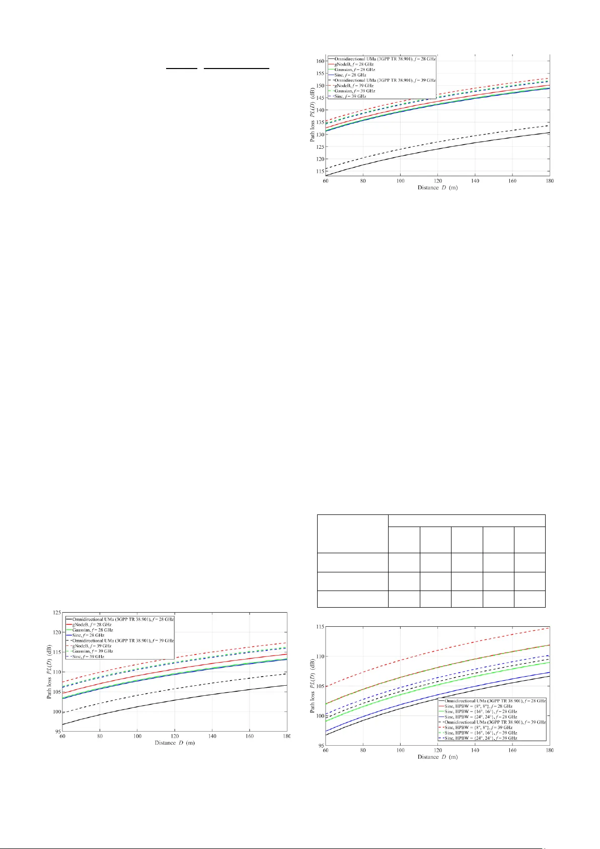
The paper has b een presented at the 2025 35th Inter national Conference Radioelek tronika ( RADIOELEKTRONIKA) , Hnanice , Czech Rep ublic , 12 -14 May 2025 . https://do i.org/10.1109/RADIOELEKTRO NIKA656 56.2025.11008380 This research was f unded in part by the National Science Center (NCN), Poland, grant no. 202 1/43/I/ST7/03294 (MubaMilWav e). For this p urpose of Open Access, the author has applied a CC -BY pu blic copyright licen se to any Author Accepted Man uscript (AAM) version arising from this submission. Millimeter W ave Path Loss for Diverse Antenna Patterns in Outdoor Environment Jarosław Wojtuń † , Cezary Ziółkowski , Jan M. Kelner , Paweł Skokowski , Niraj Narayan ⁑ , Rajeev Shukla ⁑ , Aniruddha Chandra ⁑ , Radek Závorka ‡ , Tomáš Mikulášek ‡ , Jiří Blumenstein ‡ , Ondřej Zelený ‡ , and Aleš Prokeš ‡ Institute of Communications Systems, Faculty of Electronics, Military University of Technology , 00 -908 Warsaw, Poland ⁑ Department of Electronics and Communication Engineering, National Institute of Technol o gy Durgapur , 713209 Durgapur, India ‡ Department of Radio Electronics, Brno University of Technology , 61600 Brno, Czech Republic † jaroslaw.wojtun@wat.edu.pl Abstract — Empirical path loss models are defined f or a specific antenna system used during measurements and characterized by a pa rticular radiation pattern and main lobe beam width. In this paper, we propose a novel ap proach to modifying such a model to estimate path loss for antenna systems with different radiation patterns an d beam widths. This method is based on a multi-ellip tical propagation model, enabling a more flexible adaptation of the path loss model. The paper presents the general concept of the proposed method and numerical study results demonstrating the influence of the antenna pattern shape a nd its beam width o n path loss estimation. Keywords — millimeter wave, p ath loss, an tenna pattern, urban environment, radio wave propagation I. I NTRODUCTI ON The development of communicatio n technologies and the growing deman d for high-qual ity broadband servic es have led to the i ntensive uti lization of the millime ter -wave (mmWave) spectrum in fi fth-generation (5G) s ystems. This s pectrum, known as frequenc y range 2 (FR2), i.e., 24.25 – 71 GHz , has enabled the allocati on of signi ficantly wider channels tha n traditi onal sub-6 GHz bands, i.e., fre quency range 1 (FR1) 410 MHz – 7. 125 GHz, wh ich in turn allows for higher transmissi on speeds and better su pport for advanced applicati ons requiring low latency. As a result, m mWaves play a cruci al role in the implementati on of high-capacity networks and the simultaneous servicing of a la rge number of devices [ 1], [2]. However, m mWave propagatio n encounters si gnificant challenges rela ted to h igh si gnal attenuation and susc eptibility to inter ference and environmental obstacles. Compared to FR1 bands, mmWaves have a shorter range and experien ce stronger propagati on loss es. To miti gate t hese nega tive effects, mmWave s ystems employ advanced ant enna arra y s with narrow beams and high directi onal gains, e.g., massive multiple-i nput-multi p le-outp ut (MIMO) [3]. This enables efficient transm ission over relativel y short d istances , m akin g mmWaves partic ularly we ll-suited for densely deployed pico- and femto cells, formin g ultra-dense networks (UDN) [4], [5]. To effectivel y l everage the capabiliti es of antenna systems in the FR 2 range, precise radi o wave propa gation modeli ng is crucial. Traditio nal models, such as those presented i n the 3rd Generatio n Partners hip Project (3GPP) Te chnical Re port (TR) no. 38.901 [6], are initially d esigne d for omnidirecti onal antennas, necessit ating additi onal algorithms to account for directi onal ante nnas. However , impleme nting thes e algorith ms invol ves high computational costs . An alternati ve approach is to use e mpirical propagation models derive d fr om measureme nts, which can better reflect real-world propagati on conditio ns. Howeve r, these models are typical ly developed for specifi c antenna sys tems [7], [8]. In this paper, we propose a novel method for determining a dire ctional path loss (PL) model for any bea m width and shape of an antenna pattern based on an omnidirectio nal PL model. This i nnovative approach to modeling propagati on losses for m mWave b ands is based on a numeri cal c alculation and chara cterizes by low comput ational requirements in relatio n to the simulatio n soluti ons proposed by 3GPP TR 38.901 [6 ]. The in put fact or for PL calcula tions is the omni directional PL model. It may be obtai n ed based on measuremen ts in a real environme nt using a narrow-be am d irecti onal antenna and then synthesiz ed [8], [9]. Another approach may be to u se omnidirecti onal PL models proposed by the 3 GPP standard [6]. In t he paper, we adapt the second one. A key aspect of this modificat ion involves transformati ons based on a multi-elliptical propagation mo d el ( MPM) [10], [11], [12]. W e shortly descri be how MPM-based numerical calculat ions determine the modified PL. Then, we s how the adaptatio n o f t he proposed solu tion to calculate the directio nal PL for divers e antenna pattern models and v aried half-power beam widths (HPBWs). These analyses are presen ted for two mmWaves bands, i.e., 28 and 39 GHz, and outdoor urban environme nt, considerin g both line- of -sight (LOS) and non- LOS (NLOS ) conditions . The rest of the paper is organized as follows. Secti on II shows different approach to m odeling radiation power pattern of antenna systems. Methodolo gy of determinati on d irecti onal PL model based on omnidirectiona l one a nd t he MPM is described in Section III. Exemplary res ults and their analysis, we show in Secti on IV. Finall y , Section V contains the paper summary. II. A NTENNA P ATTERN M ODELS A power radiation pattern is one of the antenna system' s basic characte ristics . The pattern is a three-dimension al (3D) character istic defined in the elevation and azimuth planes. Our researc h uses a simplifie d, two-dimensional (2D) MPM. Therefore , in the r est of the p aper, w e anal yze t he patte rn o nly in the az imuth plane (i.e., for an elevatio n of ). The actual ante nna pattern is measured in an anechoic chamber. Such a patter n is usually not symmetri cal, which results from the imperfecti ons o f the antenna system elements. In practice, we can indicate symmetr ies in th e patt ern apart from some small deviati ons. Therefore, si mplified pat tern models are usually used instea d of real patterns for calculat ions . The si mplest models, s uch a s Gaussia n, consider only main lobes of antenna patterns. While, more compl ex ones, such as Sinc, also allow for considerin g t he side lobes of antenna patterns [13] . For more complex anten na syste ms, t he use of the mentioned models may sometimes be insu fficient. In such cases, more c omplex patter ns shoul d be used. In our research, we additionall y use a realis tic patte rn model of the massive MIMO system, i.e., a v ertical patch as an antenna array of elements. The main lobe HPBWs of t he BS ante nna be am are and for t he azimut h (i. e., horizontal ) and elevation (i. e., vertical ) planes, respecti vely. The UE beam wi th HPBWs equal to and fo r th e azimuth and elevation p lanes, r especti vely, is gene rated by a single ante nna element. A realistic pattern for such a 5G base station (gNodeB) antenna system is generat ed based on t he methodolo gy recommen ded by the 3GPP [14] and Internati onal Telecommuni cation Union (ITU) [15] . The user equipment (UE) beam with HPBWs equal to and for the azimuth and elevatio n planes, respectivel y, is generate d by a single antenna element. The gNodeB, Gaussian, or Sinc antenna patter n models are used as the transmitti ng antenna. While UE pattern is applied as the receivin g antenna . These antenna patterns in the azimuth plane are illustrated in Fig. 1 [13]. Fig. 1. Power beam antenna pat te rn models i n azimuth plane co nsidered in our studies. III. M ETHODOLOGY OF P ATH L OSS C ALCULATION A. Multi -elliptical Propa gation Model Geometry- based propagation models enable radio signal scatterin g areas to be modeled using appro priate geometric structures . In practic e, various probability d istributi on s are addition ally used to different iate scatte ring both on a plan e and i n space, enhancin g the realism of this approac h. Geometry- based stochastic models (GBSMs) consider both the environme nt's geometry (e.g., buildi ngs, obstacles) and the statistic al prope rties of radio wave pr opagation r esulting from physical phenome n a such as scattering, reflectio n, and diffracti on. This allows for obtaining realisti c res ults with signific antly lower c omputational c omplexity than determinis tic models, such as ray tracing [16]. The abilit y to adjust th e shape and size of geometric structures a nd the parameters of statistical d istributions allows for the adaptation of GBSMs to various environme n ts and propagati on conditions. Resea rch f indi ngs indicate that these models effective ly capture the variabil ity of the r adio environme nt, elimin ating the need for precise geometric represent ation of ea ch object – an essential requirement in determinis tic methods . In summary, GBSMs serve as a compro mise betwee n simple empirical models and comple x determinis tic propagati on models. Due to thei r f lexibi lity and computatio nal effici ency, the y are wide ly used in the analys is of radio wave propagat ion, particularl y in modern wireless communicati on systems [ 16]. In the modificati on method , we propose to apply the MPM. In our opinion, the MPM is one of the few GBSMs in which the geometric structure can be direct ly relate d to the radio cha nnel transmiss ion character istics. In th is case, a power dela y profile (PDP) , , is used to generate a coaxial multi-ellipti cal struc ture, in the foci of which the transmitt er (Tx) and receiver ( Rx) are locate d. The size of the ellipse (its major and minor axes, ) is defined b y the character istic PDP d elays th at describe the time-cl u sters in a radio channel . O n the other hand, the powers of these clusters are used for defining the amplit udes of individ ual p aths. In this paper, we use 2D MPM [12] . Generally , you can also consider the elevati on plane and then in 3D, we use multi-semi-elli psoidal geometry structur e [10], [11], [ 12]. Fig. 2 depicts the geometr y struct ure of scatte ring areas i n 2D MPM [12]. Fig. 2. Geometry str ucture of scattering areas in MPM. The MPM is u sed, i.a., to determin e a power azimuth spectrum (PAS) , , fo r a specific distance , . In this procedur e, we assume that the i ndividual propagatio n path s are grouped into time-clus ters resulting from the PDP. For paths with , we have so-called delayed scatteri ng components . For NLOS conditions, paths wi th form the so -called local scatte ring components . They are modeled by the von Mises distributio n, the shape of which is define d by the local scat tering intensity coeffici ent. Unde r LOS conditio ns, for , there is an additional direct path component, which is defined by the Ricia n K -factor [10], [11], [12]. B. Mod ification of Pa th Loss Model Simplistic ally, the developed PL modificat ion method is based on t he followi ng equation in a loga rithm scale: () where and are so-ca lled the input and output PLs for omnidirectional and directional an tenna patterns, respectively, an d means the PL mo dification coefficient . To determine the coefficient, w e calculate the PASs for the omnidirecti onal antenna, and the anal yzed directi onal antenna, , using t he MPM . Theref ore, () where and are the gains of t he omnidirectio nal Tx and Rx anten nas, respectively, and are the gain s of the omnid irectional Tx and Rx antennas, respectively. As we mentio ned, to calculat e the input PLs for a s pecific distance range, we use the 3GPP standar d p ropagati on model [6]. Next, the PL modi fication coefficient is dete rmined based on the MPM. We can consider antenna pattern models with any shapes and differ ent HPBWs in the MPM calculatio n. A detail ed and analytical descriptio n of the proposed modificat ion meth od is presented in [17]. This w ork als o shows the method verificatio n based on empirical measureme nts for mmWa ve. IV. R ESULTS AND A NALYSIS A. Assump tions for Simulatio n Studies The input PLs for an omnidir ectional antenna pattern are determin ed based on the 3GPP TR 38.90 1 [6]. We perform calculat ions for the distance betwee n the Tx and Rx varies from to . We additi onally conside r the intensit y coefficie nt of the loc al sca ttering components equal t o . The trans mitting and receivi ng ante nnas are looking at each other, i.e., full bea m alignment – and (see Fi g. 2). The p ropose d approa ch requires the use of PDP to determin e t he geometric stru cture of the MPM. For this purpose, we use the tapped-delay line (TDL) models defined in the 3GPP 38.90 1 [6], i.e., TDL-C and TDL-E for NLOS and LOS conditions , respectively. These normaliz ed TDLs are adapted to selected propagati on enviro nment and frequ ency range by multiplying them by the appropriate delay spread, . In our s tudy, we choose the normal-dela y profile, urban macro (UMa) scen ario, and or for the carrier frequency, , e qual to or respecti vely. In TDL-E, the Rician K-factor is equal to . B. Imp act of Antenna Pa ttern Model In t he fi rst st udy, we analyzed three different antenna pattern models. The HPBW of the realistic gNodeB pattern model results from the number of anten na array elements (see Section II). Therefore , we considered the same HPBW in the Gaussian and Sinc models. The obtained results for two frequenci es, 28 and 39 GHz, are illustrat ed i n Fi gs. 3 and 4 f or LOS and N LOS conditions , respecti vely. Fig. 3. PL versus distance for diverse antenna patterns under LOS conditions. Fig. 4. PL versus distance for diverse antenna patterns u nder NLOS conditions. The analysis of the res ults shows that the PL increases wit h increasi ng frequ ency. T he resu lts obtai ned usi ng the Gaussi an and Sinc models are similar, altho ugh the first one only considers the mai n lobe. The PL for g NodeB is sli ghtly lar ger than for the oth er two models. Moreove r, using directi onal antennas introduces l arger PL in relation t o the input omnidirecti onal ant ennas. However , it s hould be r emembered that the higher gains of the directional ante nnas infl uence on the improveme nt of the wireless link power budget. On the other hand, introdu cing an angle-selecti ve beam helps reduce interfer ence and phase differenc es in the propag ation paths reaching t he Rx. C. Influence of Antenna Beam Width To dete rmine the i mpact of t he antenna HPB W on PL, we employed our method with the UE and Sinc antenn a patterns for the Rx and Tx, respectiv ely. We selected three different HPBWs for t he Sinc antenna, namely , , a nd . In o ur study, the HPBW s on the azi muth an d elevatio n planes are assumed to be ide ntical. Our values are consiste nt with real - world antenna parameters . Table I presents typical values for the Ka-band (26 – 40 GHz) directio nal horn antenna paramete rs from Eravant [18]. The results are shown in Figs. 5 and 6 for LOS and NLOS conditio ns , res pectively. TABLE I. K A – BAND H ORN A NTENNAS P ARAMETERS Parameters Antenna [18] SAR - 1532- 28 - S2 SAR - 1725- 28 - S2 SAR - 2013- 28 - S2 SAR - 2309- 28 - S2 SAR - 2507- 28 - S2 3 dB HPBW in elevation plane (˚) 33 23 14 10 7 3 dB HPBW in azimuth plane (˚) 33 24 16 11 9 Gain (dBi) 15 17 20 23 25 Fig. 5. PL versus dist ance for different HPB Ws under LOS conditio ns. Fig. 6. PL versus dist ance for different HPB Ws under NLOS conditions . The incr ease in HPB W causes a decrease in PL. Under LOS condit ions, the g raphs for HPBW e qual to approach those correspondi ng to directional antennas (see Fig. 5 – black and blue lin es). This shows that the PL for antennas with HPBW larger t han the analyze d can only slightly i ncrease compared to omnidir ectional antennas. This situati on result s from the fact that the domina nt direct path is most important . The s cattering dela yed c o mpone nts onl y sli ghtly a ffect t he P L result. For NLOS conditi ons, this situatio n looks different. The lack o f a direct path ca uses delayed components to play a crucial role in the PL. In this case, the narr ow-beam ante nna signific antly f ilte rs spatiall y the propagati o n paths arriving from directions other than the one defined by the main beam lobe. V. S UMMARY This p aper presents a novel m etho d for modifying the omnidirecti onal PL model using MPM-base d numerica l calculat ions. Di rectional PL models define d for different antenna patterns and HPB Ws result from the applie d modificat ion. The proposed approach is characteriz ed by low complexit y and compu tational time consu mption. Moreover, it allows to easil y adapt different shapes of antenna patterns. The paper presents exemplary study results for different pattern models and various HPBWs. Moreover, the resear ch considers two mmWave freq uencies, LOS a nd NLOS conditio ns. We plan to present a detailed analyti cal d esc ription of the method wit h the elevat ion plane (3 D) in [17]. In this case, the method will be based on t he 3D multi-ellips oidal propag ation model [10], [11], [12]. An empir ical verificat ion of the PL modificat ion method and potential areas of its a pplication will also be i ncluded in [ 17]. A CKNOWLEDGMENT This work was pa rtly suppo rted by the National Science Centre, Poland, under the OPUS call in the Weave program under research project no. 2021/43/I/ST7/ 03294 ac ronym ‘MubaMilWa ve’, pa rtly b y the Czech Scie nce Fou ndation under project no. 23-04304L; in part by the Military University of Technology under project no. UGB/22- 059/2025/W AT; a nd pa rtly by the MeitY, Government of India, through the C hips- to -Startup program under project no. EE -9/2/2 021-R&D- E. R EFERENCES [1] A . E. C. Redondi, C. Innamorati, S. G allucci, S. Fiocchi, and F. Matera, “A survey on future millimeter - wave commun ication applications,” IEEE Access , vol. 12, pp. 133165 – 133182, 2024, doi: 10.1109/ACCESS. 2024.3438625. [2] A . N. Uwaechi a and N. M. Mahyuddin, “A comprehensive survey on millimeter wave communications for fifth -generation wireless networks: Feasibility and cha llenges,” IEEE Access , vol. 8, p p. 6 2367 – 62414, 2020, d oi: 10.1109/ACCESS.202 0.2984204. [3] S . A. Bu sari, K. M. S. Huq, S. Mumtaz, L. Dai, and J . Rodriguez, “Millimeter -wave massive MIMO communicat ion for future wireless systems: A survey,” IEEE Commun. Surv. Tutor. , vol. 20, no. 2, pp. 836 – 869, 2018, d oi: 10.1109/COMST.2017. 2787460. [4] Y . Teng, M. Liu, F. R. Yu, V. C. M. Leung, M. Song, and Y. Zhang, “Resource allocation for ultra -dense networks: A survey, some research issues and challenges,” IEEE Commun. Surv. Tutor. , vol. 2 1, no. 3, pp. 2134 – 21 68, 2019, doi: 10.1109/CO MST.2018.2867268. [5] X . Wang et al. , “Millimet er wave c ommunicati on: A c omprehens ive survey,” IEEE Commun. Surv. Tutor. , vol. 20, no. 3, pp. 1616 – 1653, 2018, doi: 10.11 09/COMST.2018.284432 2 . [6] “5G; S tudy on channel model for frequencies from 0 .5 to 100 GHz (3GPP TR 38.901 version 1 8.0.0 Release 18),” ETSI/3GPP, ETSI TR 138.901 V18. 0.0 (2024-05), May 2 024. [Online] . Available: https://www.e tsi .org/ d eliver/ets i_tr/138900_138999/13 8901/17.01.00 _60/tr_138901v 1 70100p. pd f [7] Y . Xing and T. S. Rappapor t, “Millimeter wave and terahertz urban microcell propagation measuremen ts and models,” IEEE Commun. Lett. , vol. 25, no. 12, pp. 3755 – 3759, Dec. 2021, doi: 10.1109/LCOM M.2021.3117900. [8] T. S . Rappaport, G. R. MacCartney, M. K. S amimi, and S. Su n , “Wideband millimeter -wave p ropaga tion measureme nts and channel models for future wireless communication system d esign,” IEEE Trans. Commun. , vol. 63, no. 9, pp. 3029 – 3056, Sep. 2015, doi: 10.1109/TCOM M.2015.2434384. [9] S . Sun, G. R. MacCartney, M. K. Samimi, and T . S. Rappaport, “Synthesizing omnidirec tional antenna patterns, received power and path loss from directional antennas for 5G millimeter-wave communicati on s,” in 2 015 IEEE Global Communications Conference (GLOBECOM) , San Diego, CA, USA , Dec. 2015, pp. 1 – 7. doi: 10.1109/GLOCO M.2015.7417335. [10] C . Ziółkowski and J. M. Ke lner, “Statistical evaluati on of the azimuth and ele vation angles seen a t the output of the rec eiving anten na ,” IEEE Trans. Antennas Propag. , vol. 66, no. 4, pp. 2165 – 2169, Apr. 2018, doi: 10.1109/TAP .2018.2796719. [11] C . Ziółkowski and J. M . Kelner, “Antenna pattern in th ree -dimensional modelling of the arrival angle in simulation studies of wireless channels,” IET Microw. Antennas Propag. , vol. 11, no. 6, pp. 898 – 906, May 2017, doi: 10.1049/iet-map.2016.0591. [12] J. M. Kelner an d C. Ziółkows ki, “Multi -elliptica l geometr y o f scatterers in m odeling pr o pagation eff ect at rece iver,” in Antennas and wave propagation , P. Pinho, Ed., London, UK: IntechOpen, 2018, pp. 115 – 141. doi: 10.5772/intechopen.75142. [13] J. Wojtuń, C. Ziółkowski, and J. M. Kelner, “Modificatio n of simple antenna pattern models for inter -beam interference assessment in massive multiple-input – mu ltiple- output s ystems,” S ensors , vol. 2 3 , n o. 22, Art. no. 22, Ja n. 2023, doi: 10.3390/s 23229022. [14] “ Evolved Universal Terrestrial Radio Access (E -UTRA) and U niversal Terrestrial R adio Access (UTRA; Radio Frequency (RF) requirement background f or Active Antenna System (AAS) Base Station (BS) (3GPP TR 37.84 2 version 13.3.0 Release 13),” 3 rd Generation Pa rtnership Project (3GPP) , Valbonne, Fra nce, Tech. Rep. 3GPP TR 37.842 V13.3.0 (2019-12), R elease 13, Jan. 2020. Accessed: Feb. 0 9, 2020. [Online]. Avai lable: https://portal.3 gpp.org/desktopmodule s/Specifications/Specifi cationD etails.aspx?s pe cificati on Id=2625 [15] “ SWG Sharing Studies. Working document on characteristics of terrestrial component o f IMT for sharing and compatibility studies in preparation for WRC- 23,” I nternational Telecommunic ation Union (ITU) , Radiocomm unication S tudy Groups, Geneva, Switzerland, Document 5D /TEMP/228-E, Oct. 2020. [16] J. Chebil, H. Zorm ati, and J. B. Taher, “Ge ometry -based c hannel modelling for vehicle- to - vehicle communication: A review,” Int. J. Antennas Propag. , vol. 2 021, no. 1, p. 4293266, 2021, doi: 10.1155/2021/ 4293266. [17] C . Ziółkowski et al. , “Directional path loss prediction based on omnidirectional model for m ultipath e nvironment,” IEEE Trans. Antennas Prop ag. , (under review). [18] “ Eravant,” Eravant. Ac cessed: Mar. 05, 2025. [ Online]. A vailable: https://www.era vant.com/
Original Paper
Loading high-quality paper...
Comments & Academic Discussion
Loading comments...
Leave a Comment