Directivity Enhancement of Movable Antenna Arrays with Mutual Coupling
In conventional antenna arrays, mutual coupling between antenna elements is often regarded as detrimental. However, under specific conditions, it can be harnessed to enhance the far-field directivity (i.e., beamforming gain). Theoretically, the direc…
Authors: Wei Xu, Lipeng Zhu, Wenyan Ma
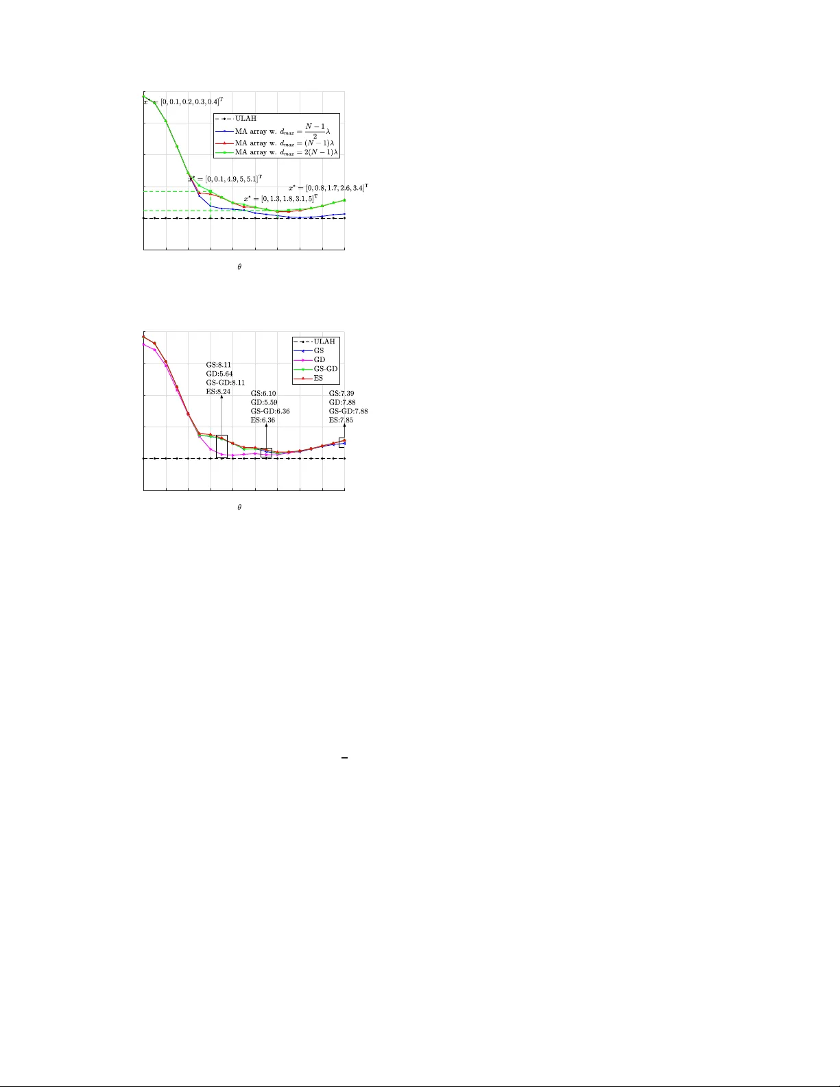
Directi vity Enhancement of Mo v a ble Antenna Arrays with Mutual Coupling W ei Xu, Gr adua te Student Memb er , IEEE, L ip eng Zhu , Sen ior Member , IEE E , W enyan M a , Graduate S tudent Memb e r , IEEE, An Liu, Senior Memb er , IEEE, a n d Rui Zhan g , F e llow , IEEE Abstract —In con ventional antenna arrays, mutual coupling between antenna elements is often regarded as detrimen t al. Howe ver , under specific conditions, it can be harnessed to enhance the far -field directivity (i.e., beam forming gain). The- oretically , the directivity of a n N -antenna superdirecti ve array ov er the endfire direction can rea ch N 2 , significantly exceeding the directi vity of a traditional uncoupled array wh ich is N ov er all directions. Thi s paper in vestigates th e potential of mutual coupling effects in mov able antenna (MA) arrays for d irectiv ity enhancement. A low-complexity algorithm called Greedy Search and G radient Descent (GS-GD) is pr oposed to optimize the antenna positi on s for maximizing the array d irectiv ity over any giv en direction, where the antenna positions are fi rst selected sequentially from discrete grid poin ts and then contin uously refined through gradient descent ( GD) optimization. Numerical results demonstrate that the optimized MA array design by exploiting t h e antenna coupling achieves significant d irectiv ity gains compared to the con ventional uni form linear array (ULA) without an tenna coupli ng over all di rections. Additionally , the proposed GS-GD algorithm is shown to appr oach th e global optimum closely in most directions. Index T erms —movable antenna (MA ) array , mutual coupling, directivity , anten na position optimization. I . I N T R O D U C T I O N In r ecent years, multip le-input multiple - output (MIM O) technolog y has achieved remarkable success in wireless com - munication systems. By increasing the nu m ber of anten nas, MIMO systems can enh a n ce bo th beamf orming an d mu l- tiplexing g a ins, thereby sig n ificantly improving the achiev- able transmission r ate. Howe ver , the physical size constrain ts of mo dern devices a n d/or infr astructures necessitate p la c ing multiple anten nas in close pr o ximity , which inevitably leads to mutu al cou p ling between a n tenna elemen ts. Su c h mutual coupling distorts the signals and is usua lly regarded to be harmfu l to the system perform a n ce. Numerou s stud ies aim to elim inate or mitigate mutua l coupling b ased on phy sical isolation or signal pr ocessing technique s [ 1], [2]. Meanwhile, se veral recen t works indicate that coup led array s can im prove the far -field directivity (i.e., beamforming /array gain in a line- of-sight scenar io) by appr opriately adjusting the effecti ve radi- ation pattern [3], [ 4]. For example, for an N -an tenna u niform linear arr ay (ULA) with th e inter-antenna spacing app r oaching zero ( i.e., sup erdirective array [5]), the directi vity o ver the endfire direction ( i.e., the d irection aligned with the linear array) can reach N 2 [3], [4]. In com parison, the directivity for an un c oupled ULA with half-wavelength spacing (i.e., This work w as supported in par t by the Nationa l Key Resea rch and Dev elop- ment Program of China under Grant 2025ZD1301900; in part by the Zhejiang Provin cial K ey Laboratory of Information Pro cessing, Communication a nd Networ king (IPCAN), Hangzhou, China. (Correspondi ng authors: L ipeng Zhu; W enya n Ma.) W . Xu and A. Liu are with the College of Information Science and Electroni c E nginee ring, Zhejiang Uni versit y , Hangzhou 310027, Ch ina (e- mails: 12231 077@zju.edu.cn and anliu@zju.edu.c n). Lipeng Zhu is with the Stat e Ke y Laboratory of CNS/A TM and the Schoo l of Interdisc iplinary Scie nce, Beijing Institute of T ec hnology , Beijing 100081, China (E -mail: zhulp@bit.edu.cn). W . Ma, and R. Zhang are with the Department of Electric al and Computer Engineeri ng, National Uni versi ty of Singapo re, Singapore 117583 (e-mail s: wenya n@u.nus.edu, elezha ng@nus.edu.sg). ULAH) is al ways N over all dire c tions. This phen omeno n of c oupled arra y s is k nown as super d irectivity . Although superdirec ti ve arrays can achieve highe r b eamform ing gains over the endfir e direction , th ey suffer from sub stantially lo wer gain over oth er direction s co mpared to unco upled arrays. In other words, the d irectivity of an anten na array depen ds on the array geometr y (i.e., antennas’ positions) an d its maximum value v aries with the wave direction. Thus, th e maxim u m directivity over all wav e d irections c a nnot be simultaneously achieved b y any array with fixed-position antennas (FP As). Recently , movable antenn a (MA) array has been pr o posed to enhance wireless com munication p erform ance b y exploiting the degrees of f r eedom (DoFs) in antenna position op timiza- tion [ 6], [7], [8]. Joint ante n na position and ro tation design is also con sidered in six-d imensional MA ( 6DMA) systems [9], [10]. Howe ver , most existing studies assume th at no mutu al coupling exists b etween MA elements b y constrain ing the inter-antenna spacin g being greater than half-wav elength [11]. While prior works ha ve demo n strated through simulation s that mutual coupling can enhance the perfo rmance of dipole MA or reconfigu rable intelligent surface (RIS) systems [12], [13], to the best of our k nowledge, a theoretical fra m ew ork quantif y ing the fund amental beamf orming g a in of gen eral M A systems remains absent. T o this end , this paper takes an isotro p ic MA array as a case study to establish a systematic f ramework for harnessing mutu al cou p ling to en h ance MA arr ay directivity . In this pap er , we first provide the expression of th e directivity to illustrate the increased beamforming ga in ob tained by the coupled MA arr ay . Then, for any given d irection, we for m u- late an o ptimization prob lem to max imize the d irectivity by designing the antenna positions with in the mov able regio n . T o solve the optimiza tion problem, we pro pose a low-complexity Greedy Search an d Gradien t Descen t (GS-GD) al gorithm, where the antenna positions a re first selected sequ entially from discrete gr id points and then con tinuously refined thr ough gra- dient descent ( GD) op timization. Extensive simulation re su lts demonstra te the directivity gain of the coup led MA array and the efficiency of the pr oposed GS-GD algorithm . Notations : 0 N and I N refer to an all-zero column vector of dimension N and an N × N identity m atrix, respectively . ( · ) , ( · ) T , ( · ) H , ( · ) − 1 and ℜ ( · ) d enote conju gate, transpo se, conjuga te tran spose, inv erse and real p art, respectively . R an d C refer to the sets of r eal numb e rs and complex numbers, respectively . | a | and || a || 2 denote the amp litude o f scalar a and the 2-norm of vector a , respecti vely . a n and A mn refer to the n -th entry of vector a and the ( m, n ) -th entry of matrix A , respectiv ely . O ( · ) deno tes the or der o f co mplexity . o ( · ) denotes higher-order infin itesimals. I I . S Y S T E M M O D E L A N D P E R F O R M A N C E C H A R AC T E R I Z AT I O N A. Dir ectivity Model of the Cou pled MA Array As illustrated in Fig . 1, we co nsider a lin ear MA ar- ray with N isotropic antenn a elemen ts lo cated alon g the x -axis. T he anten na po sition vector (APV) is den oted by Fig. 1: Illustration of the considered linear MA array . x = [ x 1 , x 2 , · · · , x N ] T ∈ R N . W e assume that the an tennas can move on a line segment of length d max , and the minimu m spacing between antenn as is d min , i.e., d min ≤ | x m − x n | ≤ d max , 1 ≤ m 6 = n ≤ N . (1) The complex far-field pattern of the MA array over the direction θ ∈ [0 ◦ , 1 80 ◦ ] is expressed as a fun ction of u , cos θ ∈ [ − 1 , 1] for n otation simplicity , where u is the d irection cosine and is propo rtional to the discrete sp atial frequ ency [4]: y ( u, x ) = w H a ( u, x ) , where a ( u, x ) ∈ C N × 1 is the steering vector (SV) : a ( u, x ) = h e − j 2 π λ x 1 u , e − j 2 π λ x 2 u , · · · , e − j 2 π λ x N u i T , with λ denoting the wav elength . T he vector w ∈ C N × 1 represents the coupled excitation co efficients, whe re the n - th entry w n is pro portion al to the current excitation on the n -th antenn a. Then, the total radia ted power of the MA ar ray is given by the integral in the angu lar domain [5]: P r ad = 1 2 Z π 0 | a H (cos θ , x ) w | 2 sin ( θ ) dθ = w H R ( x ) w , where we defin e R ( x ) , 1 2 Z π 0 a ( u, x ) a H ( u, x ) du, which is also called impedance couplin g m atrix ca u sed by power radiation interactio n between antennas [5 ], [4], and the ( m, n ) -th entry of R ( x ) th at re presents the imped ance coupling coefficient between the m - th antenna and the n - th ante n nas is R mn ( x ) = 1 2 R 1 − 1 a m ( u, x m ) a n ( u, x n ) du = sinc 2 x n − x m λ , with sinc ( x ) = sin( π x ) π x . According ly , the d irectivity o f the M A array over the direction θ , expressed in ter ms of u , takes the form of a Rayleigh q uotient ˚ G u ( x , w ) = | a H ( u, x ) w | 2 w H R ( x ) w . For a given x , th e optimal no rmalized w fo r maximizin g the directivity is given by w ∗ = R − 1 ( x ) a ( u, x ) || R − 1 ( x ) a ( u, x ) || 2 , yield ing the max imum directivity over u as a function of the APV : G u ( x ) = a H ( u, x ) R − 1 ( x ) a ( u, x ) . (2) In most existing works for MIMO system d esign, impedanc e coupling is neglected by co nstraining th e in te r-antenn a spacing being greater th a n half-wavelength, since the sinc functio n becomes n egligible for argumen ts larger th a n 1. Under this assumption, th e radiated p ower , optimal be a mformin g vector, and maximu m d ir ectivity simplify to P r ad = w H w , w ∗ = a ( u, x ) / √ N , and G u = N , respectively . B. Dir ectivity Gain Ana lysis Direct an alysis of th e rela tio nship betwe e n APV an d d ir ec- ti vity in (2) is ch allenging for a gen eral ar ray , prim arily due to the presence of the inverse co upling m atrix R − 1 ( x ) . T o facilitate analysis, we interpret the coupling matrix R ( x ) as the Gram matrix of th e pattern function s { a n ( u, x n ) } N n =1 with the inn er pr oduct d e fin ed as h a m ( u, x m ) , a n ( u, x n ) i , 1 2 Z 1 − 1 a m ( u, x m ) a n ( u, x n ) du. where a n ( u, x n ) = e − j 2 π λ x n u is the n - th entry of the SV a ( u, x ) . T o ortho gonalize these patter n functions, we a p ply Cholesky decomposition den oted by R ( x ) = L ( x ) L H ( x ) . The in verse of the re su lting lower -triang ular matrix, L − 1 ( x ) , actually serves as th e transfo rmation matrix that explicitly constructs a set of orth o norma l pattern fu nctions (or effectiv e SV) ˇ a ( u, x ) = ( L ( x )) − 1 a ( u, x ) v ia Gr am-Schmid t pro- cess. This process proceed s orth ogono rmalization recursively , with the n -th, n = 1 , 2 , · · · , N , pattern fun ction a n ( u, x n ) orthon ormalized as: ˜ a n ( u, x n ) = a n ( u, x n ) − n − 1 X m =1 h ˇ a m ( u, x m ) , a n ( u, x n ) i ˇ a m ( u, x m ) , (3a) ˇ a n ( u, x n ) = ˜ a n ( u, x n ) p h ˜ a n ( u, x n ) , ˜ a n ( u, x n ) i . (3b) By defining the effective beam formin g vector as ˇ w = L H ( x ) w , the dir e c ti vity simplifies to a can onical Rayleigh quotient form ˚ G u ( x , w ) = | ˇ a H ( u, x ) ˇ w | 2 ˇ w H ˇ w . The o ptimal ef fective beamfor ming vector is thus ˇ w ∗ = ˇ a ( u, x ) || ˇ a ( u, x ) || 2 , and the corre- sponding max imum dir ectivity is given by : G u ( x ) = || ˇ a ( u, x ) || 2 2 = N X n =1 | ˇ a n ( u, x n ) | 2 , (4) which are consistent with results in (2). This transfor mation incorpo rates the co upling matrix R ( x ) into the effectiv e SV ˇ a ( u, x ) , yielding a math ematical form iden tical to th at of an u n coupled arr ay . The key difference is that the elem ents in th e effective SV , i.e. , { ˇ a n ( u, x n ) } N n =1 , ar e g e nerally n ot unimod ular, owing to the transform ation by ( L ( x )) − 1 . This formu lation re veals a fundamental insight. For any giv en FP A array , the average d ir ectivity over the entire ang ular space is 1 2 R 1 − 1 P N n =1 | ˇ a n ( u, x n ) | 2 du , which is al ways eq u al to N because th e e ffective pattern functions are orthono rmal, as defined in (3). In particular, for arrays with elem ents located at in teger multiples of h alf-wav elength (includ ing ULAH), we have R ( x ) = I N , ˇ a ( u, x ) = a ( u, x ) , and thus the directivity remains a constant of P N n =1 | a n ( u, x n ) | 2 = N over all direction s. In contrast, for MA arrays, th e directivity over any direction can exceed N by le vera g ing the coupling effect v ia APV optimiza tio n, which is de m onstrated by the following three exam ples. 1) Example I: W e first con sid e r a simp le two-antenna case (i.e., N = 2 ). W e set x 1 = 0 with o ut loss of gen e rality . Based on ( 3), th e effectiv e pattern function s a r e given b y ˇ a 1 ( u, 0) = 1 , ˇ a 2 ( u, x 2 ) = a 2 ( u, x 2 ) − sinc 2 x 2 λ q 1 − sinc 2 2 x 2 λ . Then the directivity over any given u can be expressed as G u [0 , x 2 ] T = 2 1 − co s 2 π x 2 u λ sinc 2 x 2 λ 1 − sinc 2 2 x 2 λ . 0 0.5 1 1.5 2 0 1 2 3 4 Directivity (0.72,2.55) (1.19,2.24) (0,4) Fig. 2: Directivity versus x 2 λ for N = 2 and u = 0 , 0 . 5 , 1 . 0.5 1 1.5 2 0 0.5 1 1.5 2 (a) n = 2 . 0.5 1 1.5 2 0 0.5 1 1.5 2 (b) n = 3 . Fig. 3: For an ULA with d > λ 2 , approx imation of | ˇ a n ( u, x n ) | 2 via (5) against squared magnitude of (3b) versus d for n = 2 , 3 and u = 0 , 0 . 5 , 1 . Over the broad side direction (i.e., u = 0 ), this simplifies to G u = 2 1+sinc ( 2 x 2 λ ) . The o ptimal p osition x 2 ≈ 0 . 72 λ yields a maximum directivity of G ∗ u ≈ 2 . 55 . Over the endfire directio n (i.e., u = 1 ), x 2 → 0 yields superdirectivity G ∗ u → 4 . Both cases a chieve a d irectivity larger than the num ber of anten nas ( N = 2 ). Howe ver , over other d irections, the optimal solution for x 2 becomes analytically com plicated. T he relation ship between directivity of th e two-antenna MA array a n d x 2 is depicted in Fig. 2. 2) Example II: F or an array with inter-antenna spacing greater than half-wavelength, i.e., | x m − x n | > λ 2 , ∀ m 6 = n , the coupling ef f ects ar e weak. For conv enience, we define k mn = 2 π ( x m − x n ) λ , ∀ m 6 = n , and th e magnitude o f coupling coefficient sinc k mn π < 0 . 22 since k mn π > 1 . By neglecting higher-order te r ms o sinc k mn π , ∀ m 6 = n , the orthogonal- ization in (3) can be simplified as follows: ˇ a 1 ( u, 0) ≡ 1 , ˇ a 2 ( u, x 2 ) ≈ − sinc k 12 π + a 2 ( u, x 2 ) , · · · , ˇ a N ( u, x N ) ≈ − N − 1 X n =1 sinc k nN π e − j k nN u + a N ( u, x N ) . Under this fir st-order ap proxim ation, the squ ared magnitud e of eac h or thogon alized p attern simplifies to | ˇ a n ( u, x n ) | 2 ≈ 1 − 2 n − 1 X m =1 sinc k mn π cos ( k mn u ) . (5) T o validate this approximation , we con sider an ULA with element spacing d > λ 2 , i.e., x n = ( n − 1 ) d . T he behavior of th e approximated | ˇ a n ( u, ( n − 1) d ) | 2 in (5) as a functio n of d λ is illustrated in Fig. 3. Consequently , the overall directivity G u ( x ) is given by N X n =1 | ˇ a n ( u, x n ) | 2 ≈ N − 2 X 1 ≤ m G u ( x ( t ) ) ; on the other h and, it satisfies the position co nstraints in (7b). Otherwise, α is halved in a backtrack ing line search until the cond itions are satisfied or α is be low the threshold ǫ . C. Algorithm Summary The prop osed algorith m is summarize d in Algorithm 1. Lines 1-4 corre spond to the GS stage, while lines 5 -16 co rre- spond to the GD stag e. Th e co n vergence of GD is g uaranteed because the objectiv e function is u pper-bound ed, and non- decreasing in iteratio ns. Th e co m putationa l com plexity is analyzed as follows. The dir ectivity ev alu a tio n in (4) of M candidate grid points fo r M n +1 in line 3 can be reduced Algorithm 1 GS-GD for An tenna Position Optimiza tio n Input: N , θ , λ, d max , d min , d g , α 0 , ǫ . 1: %% T he first stage: GS to select the antenna positions from grid points. 2: for n = 1 · · · N − 1 do 3: Optimize M n +1 by solving (8). 4: end for 5: %% The second stage: GD to continuo usly refine the positions via backtracking line search. 6: Initialize x (0) = x GS . 7: for t = 0 · · · T − 1 do 8: Compute the gradients ∂ G u ( x ) ∂ x n , n = 2 , · · · , N as (9). 9: Initialize α = α 0 , r = − 1 , x test = x ( t ) . 10: while r < 0 or x test does not satisfy (7b ) do 11: Update x test as (10). 12: Compute r = G u x test − G u ( x ( t )) . 13: α ← 0 . 5 α . 14: if α < ǫ then 15: Return x ∗ = x ( t ) . 16: end if 17: end while 18: Update x ( t + 1) = x test . 19: end for 20: x ∗ = x ( T ) . Output: x ∗ . Parameter V alue Number o f antennas N 5 W av elength λ 0 . 3 m Minimum spa c in g d min λ/ 10 = 0 . 03 m Aperture size d max N − 1 2 λ , ( N − 1) λ , 2( N − 1) λ Grid spa c in g d g λ/ 20 = 0 . 015 m GS-GD iterations T 5 Initial step size α 0 1 T oleran c e ǫ 10 − 3 T ABLE II: Main simulation parameters. to computing { ˇ a n +1 ( u, x ) } x ∈ ˜ X with complexity O ( M n 2 ) , since ˇ a m u, x GS m n m =1 are r ecursively computed in former steps. The comp lexity of calculating the gradien ts in line 8 is O N 2 . Th e com plexity of calc u lating the objective f unction in line 12 is O N 3 , and thus th e maximum complexity of the en tire wh ile loop is O log 2 α 0 ǫ N 3 . Hence, the overall computatio nal com plexity of th e p r oposed Algorith m 1 is O M N 3 + T N 2 + log 2 α 0 ǫ N 3 . I V . N U M E R I C A L R E S U LT S This sectio n presen ts numeric a l re sults to validate the direc- ti vity e n hanceme nt of the MA array by takin g into the antenna coupling effect and the perfor mance of the pr oposed GS-GD algorithm . For c la r ity , the directivity is pr esented as a fu nction of the angle θ rath er than u in this section. Further more, the resu lts are confined to θ ∈ [0 ◦ , 9 0 ◦ ] , as the directivity is symmetric w .r .t. 90 ◦ . The main simulation parameters are summarized in T able II for ease of reference. First, we com pare the dir ectivity of th e optimized cou p led MA ar ray with the trad itional ULAH. In simulations, we employ an ES over all d iscretized g rid points to app roximate the glo bally optim al solution for prob lem (7). T he resu lts are shown in Fig. 4. The results dem onstrate that, over all directions, the opti- mized MA array achiev es a hig her directivity compared to the 0 10 20 30 40 50 60 70 80 90 (°) 0 5 10 15 20 25 Directivity (90,7.8) (60,6.1) (30,9.2) (0,24.2) Fig. 4: Directivity of the coupled MA array compared to the UL AH in different values of θ and d max . 0 10 20 30 40 50 60 70 80 90 (°) 0 5 10 15 20 25 Directivity Fig. 5: Comparison of the propo sed GS-GD algorithm with baselines in different values of θ . ULAH. Specifically , whe n θ → 0 ◦ , the supe r directive array is o ptimal, and th e direc tivity appr oaches N 2 . As θ increases, the optim al antenna positions exhib it irregular patterns, and there is at least 2 0% imp rovement in the directivity fo r the coupled MA ar ray compar ed to the trad itional ULAH without antenna cou pling wh en the movable region is sufficiently large. Wh e n θ → 90 ◦ , the o ptimal arr ay conver ges to a nearly uniform a r ray with spacing ar ound 0 . 8 λ , and there is around 50 % directivity g ain, which are consistent with the analysis in Section II- B2. Ad ditionally , over the vast major ity of d irections, the maxim um directivity for d max = ( N − 1 ) λ is the same as that for d max = 2 ( N − 1) λ , bo th o f which substantially exceed the directivity f or d max = 1 2 ( N − 1) λ , which implies that d max = ( N − 1) λ is sufficient to achiev e most of the directivity gains in practice. Next, we evaluate the perform ance of the propo sed GS-GD algorithm a gainst the following baseline m ethods: • ES: This method selects anten n a position s from grid points, and com pute the directivity of all feasible A PV cases to find the maximum directivity . • GS: This meth o d only perfor ms the first stage as men- tioned in Section III-A. • GD: This method in itializes the APV as a ULAH, and then perf orms the secon d stage as mentio ned in Section III-B, wher e we set T = 30 in s imulation s to e n sure conv ergence. • ULAH: For ULAH witho ut an tenna c oupling , the direc- ti vity is N over all directions. The perform ance of th e algorithm s is evaluated in Fig. 5. As shown in the figure, the p erform ance of the propo sed GS-GD approach e s ES over most directio ns. Moreover , GS- GD o utperfo rms the two baselines (GS and GD) over all directions. Th is su p eriority arises from its ab ility to mitigate the in herent limitations of both methods: G S is constrained by its sequential optimization process, which myop ically adjusts individual antenna p ositions, thus lacking the capability to co-optim ize th e entir e array , wh ile GD is pron e to local optima wh en initialized fro m a ULAH. By le veraging both approa c h es, GS-GD enab les a more robust search, c o nsistently conv erging to a so lu tion c lo ser to the global o p timum. V . C O N C L U S I O N In this p aper, we inv estigated the directivity of MA arr ays with antenna coup ling. In contrast to traditional uncoupled arrays, coupled MA ar rays can e nhance the d irectivity (i.e., beamfor ming gain) by co ncentratin g the rad iated p ower more effecti vely toward specific directions. W e aimed to optimize the positions of anten nas f or maximizing the dir ectivity of the MA ar ray over any given d irection. A low-complexity GS- GD a lgorithm was proposed , wh e re the antenna positions ar e first selected seque ntially from discrete g rid poin ts thr ough GS and th en contin uously refined throug h GD optimization. Numerical results d emonstrated the direc tivity ga in o f the optimized coup led MA array and th e efficiency of the proposed GS-GD algorithm. R E F E R E N C E S [1] J. G, I. Singh, and D. K . Choudha ry , “Gain and isola tion improv ement techni ques for MIMO antenna: A compendi ous survey , ” Resul ts in Engineerin g , vol. 25, p. 104482, Mar . 2025. [2] T . T . V o, L. Ouvry , A. Sibille, and S. Bories, “Mutual coupling modeling and calibra tion in antenna arrays for A OA estima tion, ” in 2018 2nd URSI Atl. R adio Sci. Meet. -RASC . Gran Cana ria: IEEE, May 2018, pp. 1–4. [3] T . L. Marzet ta, “Super-di recti ve antenna a rrays: Fun damentals and ne w perspecti ves, ” in 2019 53rd A silomar Conf . Signals Syst. Comput. Paci fic Grov e, CA, USA: IEEE, Nov . 2019, pp. 1–4. [4] A. Pizz o and A. Lozano, “Superdi recti vity in linear holographic MIMO, ” in 2024 IEEE 25th Int. W orkshop Signa l Pr ocess. Adv . W ir el. Commun. SP A WC . Lucca, Italy: IEEE, Sep. 2024, pp. 386–390 . [5] L. Han, H. Y in, M. Gao, and J. Xie, “ A superdire cti ve beamforming approac h wi th impedance coupli ng and fi eld coupling for compact antenna arrays, ” IEEE Open J. Commun. Soc. , vol. 5, pp. 7262–7277, 2024. [6] L. Zhu, W . Ma, and R. Zhang, “Modeling and perfo rmance analysis for mov able antenn a enabled wireless communications, ” IEEE T rans. W ir el. Commun. , vol. 23, no. 6, pp. 6234–6250, Jun. 2024. [7] — —, “Mov able antenna s for wire less communication : Opportunitie s and chall enges, ” IEEE Commun. Mag. , vol. 62, no. 6, pp. 114– 120, Jun. 2024. [8] W . Ma, L. Z hu, a nd R. Z hang, “Compressed sensing ba sed cha nnel estimati on for m ov able ante nna communicat ions, ” IEE E Commun. Lett. , vol. 27, no. 10, pp. 2747–2751, Oct. 2023. [9] X. Shao, Q. Jiang, and R. Zhang, “6D mov able antenn a based on user distrib ution: Modeling and optimization , ” IEEE T rans. W ir el. Commun. , vol. 24, no. 1, pp. 355–370, Jan. 2025. [10] X. Shao, R. Zhang, Q. Jiang, and R. Schober , “ 6D mova ble antenna enhanc ed wireless netw ork via discrete position and rotati on optimiza - tion, ” IE E E J. Sel. Areas Commun. , vol. 43, no. 3, pp. 674–687, Mar . 2025. [11] L. Zhu, W . Ma, and R. Z hang, “Mov able-anten na array enhanced beam- forming: A chievi ng full array gai n with null steeri ng, ” IEEE Commun. Lett. , vol. 27, no. 12, pp. 3340–3 344, Dec. 2023. [12] P . Mursia, F . Dev oti, M. Rossanese, V . Sci ancalep ore, G. Gradoni, M. D. Renzo, and X. Costa-Pére z, “T3dris: Adv ancing conformal ris design through in-depth analysis of mutual coupling ef fects, ” IEE E T rans. Commun. , vol. 73, no. 2, pp. 889–903, Feb . 2025. [13] J. Zhu, F . Han, Y . Guo, and Y . W ang, “Mutual coupling-en hanced mov able antenna arrays: Breaking minimum-spacing constraint s, ” IEEE Commun. Let t. , vo l. 30, pp. 672–676, 2026. [14] D. Y . Levin, S. Markovi ch-Golan, and S. Gannot, “Near- field superdi- recti vity: An analytical perspecti ve, ” IEEE/ACM T rans. Audio Speech Lang. Pro cess. , v ol. 29, pp. 1661–1 674, 2021.
Original Paper
Loading high-quality paper...
Comments & Academic Discussion
Loading comments...
Leave a Comment