Robust High Mobility NLOS UE Beamforming Strategy for Gigantic MIMO
Maintaining robust and stable communication links in high-mobility scenarios is challenging for time-division duplex (TDD) reciprocity-based gigantic MIMO systems due to rapid channel variations, especially in non-line-of-sight (NLOS) conditions. Thi…
Authors: Josep R. Fernández Rull, Liang Liu, Henrik Sjöl
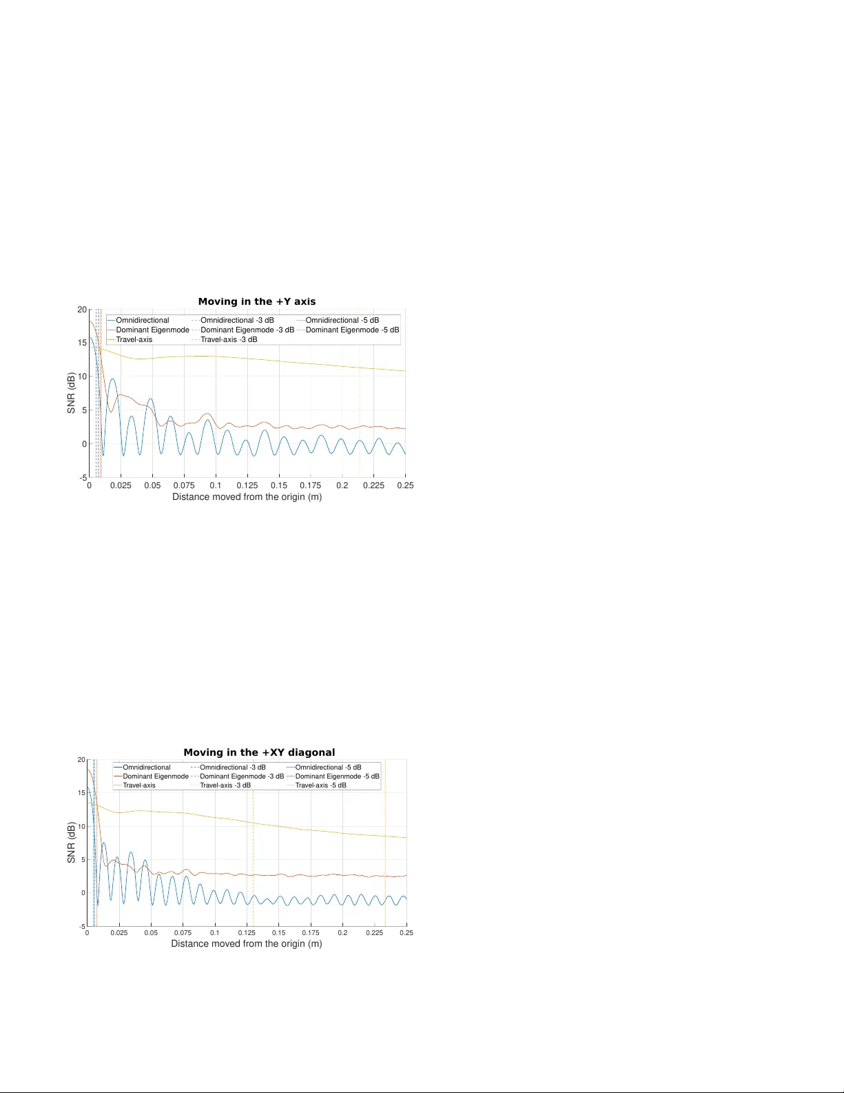
Rob ust High Mobility NLOS UE Beamforming Strate gy for Gigantic MIMO Josep R. Fern ´ andez Rull ∗ , † , Liang Liu ∗ , Henrik Sj ¨ oland ∗ , † , Juan V idal Ale gr ´ ıa ∗ ∗ Department of Electrical and Information T echnology , Lund Univ ersity , Lund, Sweden † Ericsson AB, Lund, Sweden { josep ramon.fernandez rull, liang.liu, henrik.sjoland, juan.vidal alegria } @eit.lth.se Abstract —Maintaining rob ust and stable communication links in high-mobility scenarios is challenging for time-division duplex (TDD) recipr ocity-based gigantic MIMO systems due to the rapid channel variations, especially in non-line-of-sight (NLOS) condi- tions. This paper proposes a user equipment (UE) beamforming strategy that enables a rob ust link in high mobility without incurring additional pilot overhead. The pr oposed beamform- ing strategy consists of aligning the directional beamforming with the UE’ s travel axis. Our analysis shows the optimality of the proposed tra vel-axis beamforming in minimizing the Doppler spread of the channel, which corresponds to an in- verse metric f or channel stability . This approach is further evaluated thr ough simulations in a scattering-rich en vironment, repr esentative of gigantic MIMO deployments. Numerical results confirm that movement-aligned UE beamforming enhances link rob ustness, increases achievab le data rates, and lowers pilot signaling r equirements, ther eby reducing UE power consumption. These findings highlight travel-axis aligned UE beamforming as a promising technique f or improving reliability in futur e high-mobility wir eless systems. Index T erms —beamforming, UE, high mobility , Gigantic- MIMO, Massiv e-MIMO, 6G I . I N T R OD U C T I O N The increasing demand for higher data rates, together with the need for improved energy efficienc y , has exposed the limitations of fifth-generation (5G) networks and motiv ated the mov e tow ard the sixth generation (6G) [1]. T o meet 6G requirements, wider bandwidths across centimeter-wa ve (cmW av e), millimeter-w ave (mmW av e), and sub-terahertz (THz) bands are required [2]. The shorter wa velengths in these bands enable compact arrays with man y more elements [3]. In practice, antenna configurations are being scaled up at both base stations (BSs) and user equipment (UE). For instance, exploiting cmW a ve may require roughly 4 - 8 times more BS antennas than sub- 6 GHz deployments to preserve the same physical aperture, assuming half-wa velength inter- element spacing [4], leading to gigantic MIMO [5]. This continued scaling of massiv e MIMO brings user mo- bility to the forefront, as larger arrays and higher carrier fre- quencies lead to faster channel variations that undermine beam alignment and channel stability . In high-mobility scenarios, the coherence time can become so short that con ventional beam- forming based on Channel State Information (CSI) becomes This project has receiv ed funding from the European Union’ s Horizon Europe research and innovation program under the Marie Skłodowska-Curie grant agreement No 101119643 , ultra-massiv e MIMO for future cell-free heterogeneous networks (MiFuture). impractical without excessiv e computational complexity and signaling overhead [6]. At the same time, higher carrier frequencies make it feasible to integrate compact antenna arrays at the UE, enabling UE-side beamforming to improv e the link budget and compensate for increased path loss [7]. Howe ver , the effecti veness of such directional transmission critically depends on maintaining beam alignment ov er time, which becomes increasingly challenging under mobility [6]. At mmW ave frequencies, UE-side beamforming is facili- tated by sparse propagation with only a fe w dominant paths, making directional steering effecti ve, while still requiring continuous beam selection and tracking [8], [9]. In contrast, cmW av e channels exhibit weaker line-of-sight (LOS) com- ponents and richer scattering, requiring beamforming strate- gies that account for a larger number of contributing paths [10], [11]. Under mobility , this richer multipath structure substantially increases the beam-management burden, as more frequent updates are needed to track the rapidly varying channel. Prior work on mmW av e UE beamforming sho w that, under dominant LoS conditions, the UE beam can be designed using position and velocity information to form a broad, fix ed recei ve beam that robustly covers the user’ s predicted motion over a time interv al, av oiding frequent beam updates [12]. Under NLOS mmW av e scenarios, howe ver , [13] proposed an ef ficient codebook-based beam training technique that addresses the presence of multiple comparable paths by formulating beam selection as a multi-stage optimization problem with reduced training ov erhead. In cmW a ve, multiple studies document richer scattering and less dominant LOS [10], [11], which increases beam-management overhead under mobility . Nev- ertheless, we are not aware of UE-side beamforming schemes explicitly designed for high-mobility cmW ave systems. T o address the challenges previously mentioned, this study proposes a UE-side beamforming technique in which the antenna beam is aligned with the axis of motion, thereby stabi- lizing the temporal ev olution of the channel and reducing the need for frequent CSI updates. It is shown that such travel-axis UE beamforming not only reduces signaling ov erhead, but also enhances overall communication performance by increasing data rates and providing more stable and reliable links in high-mobility and NLOS conditions. Specifically , we provide a formal proof of the optimality of this approach in minimizing the Doppler spread of the propagation channel. Furthermore, a numerical comparison between this approach, omnidirectional transmission, and dominant eigenmode transmission is pre- sented, demonstrating that maintaining a beam aligned with the UE trajectory offers clear adv antages without the need to update beamforming weights giv en a movement distance. The remainder of this paper is org anized as follows: Section II presents the system model; the proposed solution is detailed in Section III; and Section IV provides numerical results and discussion. Finally , Section V concludes the paper and outlines potential directions for future lines of work. I I . S Y S T E M M O D E L A time-domain duplexing (TDD) system is considered in which an N BS -antenna BS serves a moving N UE -antenna UE through a narrowband channel. The exposition focuses on the uplink (UL) scenario, but the results are directly applicable to the downlink (DL) counterpart due to the angular reciprocity of the propagation channel. The receiv ed vector at the BS may be expressed as y = H ( t ) w UE s + n , (1) where s is the transmitted symbol assuming single-layer transmission, w UE is the UE beamforming vector , n ∼ C N ( 0 , N 0 I N BS ) is the noise vector , and H ( t ) is the time- varying N BS × N UE channel matrix at time instant t ≥ 0 . Due to high-mobility , channel variations are considered within one coherence block, where channel estimation is performed at t = 0 . Moreov er, the UE beamforming w UE is pre-selected before channel estimation, and it is kept fixed throughout the whole coherence block. NLOS conditions are assumed, such that the direct path is blocked, and only paths via scattering objects are present. In this case, the channel matrix may be expressed as H ( t ) = H 2 diag ( α ( t )) H 1 ( t ) , (2) where H 1 ( t ) is the time-varying channel matrix between the UE antennas and the scatterers, H 2 is the fixed channel matrix between the scatterers and the BS antennas, and α ( t ) is an N sc -sized vector containing the complex baseband respond of each of the N sc scatterers. 1 T o ensure validity of the results when the UE gets relati vely close to the scatterers, we consider the non-uniform spherical wave (NUSW) near-field channel model, as presented in [14]. Note that, as we go to higher frequencies, the likeliness of being in the near-field of the objects in the en vironment increases. The channel between two points in space, p 1 and p 2 , is thus giv en by h ( p 1 , p 2 ) = 1 q 4 π || p 1 − p 2 || 2 e − j 2 π λ || p 1 − p 2 || , (3) 1 The scattering response α ( t ) is assumed time-dependent due to the dependency of the bistatic radar cross section (RCS) on the incidence angle. where λ corresponds to the wa velength. Correspondingly , the entries of H 1 ( t ) and H 2 , ∀ m ∈ { 1 , . . . , N sc } , ∀ n ∈ { 1 , . . . , N UE } and ∀ ℓ ∈ { 1 , . . . , N BS } , are giv en by [ H 1 ( t )] m,n = h ( p SC m , p UE n ( t )) [ H 2 ] ℓ,m = h ( p BS ℓ , p SC m ) , (4) where p SC m , p UE n ( t ) , and p BS ℓ are the position of the m − th scatterer , the n − th UE antenna element at time instant t , and the l − th BS antenna element, respectively . A. Beamforming considerations The BS applies a linear combining vector w BS ∈ C N BS , leading to the post-processed symbol z = w T BS y . (5) Since the UE beamforming w UE is applied at the UE prior to channel estimation, the BS can only observe and estimate the single-input multiple-output (SIMO) effecti ve channel vector h est = H (0) w UE , estimated at t = 0 through UL pilot signaling. For ease of exposition, perfect channel estimation is considered, but the gains of the proposed are not limited to that case. Assuming that the BS is unaw are of the UE mobility , the best choice for its linear combining vector is gi ven by maximum ratio combining (MRC). This choice maximizes the power of the received signal at t = 0 , and may be applied by selecting w BS = h ∗ est ∥ h est ∥ ≜ ( H (0) w UE ) ∗ ∥ H (0) w UE ∥ . (6) The instantaneous post-processing signal-to-noise ratio (SNR) at time t is then giv en by SNR ( t ) = E s N 0 w T BS H ( t ) w UE 2 , (7) where E s is the UE symbol power and N 0 is the noise power . Both the UE and the BS are assumed to ha ve their anten- nas organized into a uniform linear array (ULA) with half- wa velength spacing. For presentation clarity we focus on the 2-dimensional (2D) scenario, i.e., assuming that both ULAs are aligned in the 3rd dimension. The UE beamforming vector is then computed as w UE = 1 √ N UE a ∗ UE ( θ UE ) , (8) where θ UE denotes the UE pointing direction measured from the array broadside, and a UE ( θ UE ) is the traditional f ar-field steering vector giv en by a UE ( θ UE ) = h 1 , e j π sin( θ UE ) , . . . , e j π ( N UE − 1) sin( θ UE ) i T . (9) Back-lobe suppression is assumed at the UE array , meaning that the radiation tow ard the backward half-plane is set to zero. Under this conv ention, the UE can only steer its beam within a single 180 ◦ sector , i.e., θ UE ∈ [ − π / 2 , π / 2] . (10) This forward-only behavior may be justified by the use of partly directive antenna elements, such as patch antennas, resulting in an ef fective directivity gain of approximately 3 dB. The considered scenario is illustrated in Fig. 1, where θ mov is the angle between the travel axis and the UE broadside. The angle θ mov is assumed to be fixed within the coher- ence block, and known at the UE since it can be obtained from on-de vice information such as GPS, inertial sensors, or motion-estimation algorithms. The main goal of this work is to characterize the most suitable pointing direction θ UE that allows for increased channel coherence within the UE trajectory . Fig. 1. Illustration of the scenario. I I I . T R A V E L - A X I S B E A M F O R M I N G In this section, the main idea underlying the proposed solution is pre sented. The proposed approach relies on aligning the UE beamforming direction with its direction of motion, which is shown to be the most robust option in high-mobility scenarios. In this setting, the UE steers its transmit main lobe along the direction in which it is moving using the beamforming vector w UE defined in (8). It is well kno wn that the coherence time and the Doppler spread of the channel are inv ersely related [15]. Thus, we next focus on demonstrating the optimality of travel-axis beamforming at the UE for increased channel coherence by solving an equi valent Doppler spread minimization problem. For a multipath component departing the UE at an angle θ relativ e to the UE trav el-axis, the resulting Doppler shift is ν ( θ ) = v UE c f c cos ( θ ) , (11) where v UE denotes the UE speed, c is the speed of light, and f c is the carrier frequency . This expression sho ws that the Doppler shift depends on the projection of the UE velocity onto the propagation direction of each transmitted path. Let θ = θ UE − θ mov now denote the angle between the beam pointing direction and the trav el-axis. W e assume that the power radiated by the UE outside the main lobe is negligible. Moreov er, the main lobe has beamwidth B = 2 γ , with γ ≤ π / 2 , symmetric around the pointing direction, and we we consider a rich enough scattering en vironment such that all directions within the main lobe are associated with scattering objects. T wo different cases are studied: one where the UE trav el-axis is inside the main lobe, i.e., θ ∈ ( − γ , γ ) , and the other where it is outside the lobe, i.e., θ ∈ [ − π / 2 − θ mov , − γ ] ∪ [ γ , π / 2 − θ mov ] . Note that if the travel-direction points tow ards the backlobe area of the ULA we can equiv alently consider the opposite direction. Fig. 2. Geometry showing the beam steered at θ UE = θ + θ mov with edges at θ ± γ , which determine the Doppler spread. A. T ravel-axis outside the main lobe W e begin by considering the configuration presented in Fig. 2, where the trav el-axis lies outside the UE main lobe, i.e., θ ∈ [ − π / 2 − θ mov , − γ ] ∪ [ γ , π / 2 − θ mov ] . The maximum Doppler spread within the main lobe occurs between its two edges, at angles θ + γ and θ − γ from the travel-axis. Using (11), the maximum Doppler spread is giv en by ν max ≜ | ν 1 − ν 2 | = v UE c f c | cos ( θ − γ ) − cos ( θ + γ ) | =2 v UE c f c | sin ( θ ) sin ( γ ) | . (12) In order to minimize the channel variability in time, we should minimize this maximum Doppler spread. Since (12) corresponds to a positive value, we can equiv alently consider the squared Doppler spread ν 2 max = 4 v 2 UE c 2 f 2 c sin 2 ( θ ) sin 2 ( γ ) . (13) This squared formulation simplifies dif ferentiation with respect to the pointing angle θ , while maintaining the extrema behav- ior since squaring is a monotonic increasing function under non-negati ve input. T aking the deriv ativ e with respect to θ , and applying standard trigonometric identities, we get ∂ ν 2 max ∂ θ =4 v 2 UE c 2 f 2 c sin 2 ( γ ) sin (2 θ ) . (14) The stationary points, associated to local e xtrema, may be found by finding the roots of (14), which appear at θ = nπ / 2 , n ∈ Z . By ev aluating these v alues in (13), we can see that at θ = ± π / 2 we have maximum spread ν 2 max = 4 v 2 UE c 2 f 2 c sin 2 ( γ ) , where at least one of the values w ould fall within the considered interval θ ∈ [ − π / 2 − θ mov , − γ ) ∪ ( γ , π / 2 − θ mov ] . Although at θ = 0 we hav e a minimum, ν max = 0 , this value lies outside the considered interval. This observation indicates that the optimum θ should lie within the interval θ ∈ [ − γ , γ ] considered next. B. T ravel-axis inside the main lobe Let us now consider the case where the travel-axis is contained within the main beam, i.e. θ ∈ ( − γ , γ ) . In this case the worst-case Doppler spread occurs between the travel axis and the farthest main lobe edge, i.e., associated to max( | θ + γ | , | θ − γ | ) . Assuming without loss of generality that the main lobe edge farthest from the travel-axis corresponds to θ + γ , 2 the maximum Doppler spread inside the lobe is giv en by ν max ≜ | ν ( θ + γ ) − ν (0) | = v UE c f c | cos ( θ + γ ) − 1 | = v UE c f c | cos ( θ ) cos ( γ ) − sin ( θ ) sin ( γ ) − 1 | . (15) Considering again the squared maximum Doppler spread ν 2 max = v 2 UE c 2 f 2 c (cos ( θ ) cos ( γ ) − sin ( θ ) sin ( γ ) − 1) 2 , (16) differentiating with respect to θ , and reducing the expression through standard trigonometric identities, we get ∂ ν 2 max ∂ θ = 4 v 2 UE c 2 f 2 c sin 2 θ + γ 2 sin( θ + γ ) . (17) The roots are then at θ = nπ − γ , ∀ n ∈ Z . By ev aluating (16) we can note that θ = − γ corresponds to a minimum since ν 2 max = 0 , and the next maximum is at θ = π − γ . Howe ver , both extrema lie outside the considered interv al, since at θ = − γ we break the assumption that | θ + γ | ≥ | θ − γ | , while for the other e xtreme we hav e θ = π − γ ≥ γ since γ ≤ π / 2 . Hence, by the extreme value theorem [16] the minimum should lie at the boundary of the interval closest to θ = − γ , leading to the optimum value θ ∗ = 0 . W e hav e thus prov ed that the optimum beamforming direction to minimize the Doppler spread, equi valently to maximize the channel coherence, is giv en by aligning the beam with the trav el-axis. This is achiev ed by selecting θ UE = θ mov in (8). The previous Doppler analysis is valid for small changes of position, i.e., where the beam maintains visibility of the same scattering objects throughout the trajectory . Ho wever , it is also worth noting that, for sufficiently narrow beams pointed far aw ay from the direction of motion, the set of scatterers illuminated by the beam changes rapidly along the UE trajectory , which may create additional channel variability caused by the continual entry and exit of different multipath 2 The conv erse case would lead to the same conclusions due to the even symmetry of the cosine function. components. This reinforces the robustness of the proposed trav el-axis beamforming, which maintains longer visibility of the scattering objects within the beam. I V . N U M E R I C A L R E S U LT S Let us consider the scenario where the UE is positioned at the origin of a coordinate system, as depicted in Fig. 1, and where the system operates at a carrier frequency of f c = 10 GHz. The UE is equipped with a four-element ULA oriented perpendicularly to the direction of movement. The BS is positioned 10 m away from the UE in the x-axis and it is equipped with a ULA of 128 antennas facing the UE, corresponding to a gigantic MIMO configuration. 3 The initial UE SNR, defined as E s / N 0 , is fixed to 30 dB. Scatterers are present in the scenario, as shown in Fig. 1. For simplicity , and due to its marginal ef fect when considering a large number of scatterers in the en vironment, we assume that scatterers response does not af fect the phase, i.e., α ( t ) ∈ R N sc . Their amplitude is then given by the bistatic radar cross section (RCS), which, for the m − th scatterer , is approximated as [17] α m ( t ) ≈ RCS monostatic · cos β m ( t ) 2 , (18) where β m ( t ) is the bistatic angle for scatterer m with respect to the UE position at time t , and the monostatic RCS is assumed constant with RCS monostatic = 0 . 5 for all the scatterers. T wo different UE mobility patterns are presented in the ev aluation. In the first case, the UE mov es perpendicularly from the BS, and in the second one, the UE trav els tow ard the BS along a trajectory forming a 45 ◦ angle with respect to the BS direction. Both mobility patters are assumed to work under NLOS conditions. For each case, three dif ferent beamform- ing strategies are considered: The first one, omnidirectional transmission at the UE, referred as Omnidir ectional case. The second is directional beamforming aligned with the UE’ s direction of motion, denoted as the T ravel-axis strategy . The third assumes that the UE performs optimal dominant eigen- mode transmission by leveraging complete CSI kno wledge at the UE, estimated at t = 0 , and is referred to as Dominant eigenmode case. Although useful for the comparison, this last case is not practical, since it assumes unsuppressed back-lobes and requires extensi ve channel feedback at the UE, conditions that are incompatible with high-mobility en vironments. A. UE moving perpendicular fr om the BS For the case where the UE mov es along the Y -axis, the results are presented in Fig. 3, showing the e volution of the post-combining SNR as a function of the UE mov ement. When the UE is stationary (step 0 ), the Dominant eigenmode case provides the highest initial SNR, followed by the Omnidirec- tional case. Ho wever , once the UE begins to mov e, the SNR of both configurations degrades rapidly , whereas the T ravel- axis strategy maintains a significantly more stable SNR lev el ov er a longer distance. Assuming a maximum tolerable SNR 3 Note that the considered 2D scenario only accounts for one of the 2 dimensions of a planar gigantic MIMO array . degradation of 3 dB, the UE can mo ve up to 5 . 25 mm in the Omnidir ectional case, while up to 213 . 75 mm in the T r avel- axis case. Additionally , the Dominant eigenmode case exhibits a noticeable SNR drop after approximately 7 . 5 mm of displace- ment. This behavior further highlights the superior robustness achiev ed when the beam is aligned with the UE’ s direction of mov ement. Although the initial SNR achie ved by the T ravel- axis strate gy is lo wer than the ones for the Omnidir ectional and Dominant eigenmode configurations, this limitation can be mitigated through techniques such as adaptiv e gain control (A GC) at the receiver , which compensates for the reduced av erage SNR while preserving the improv ed temporal stability provided. 0 0.025 0.05 0.075 0.1 0.125 0.15 0.175 0.2 0.225 0.25 Dis tanc e mo v ed fr om t he origin (m) -5 0 5 10 15 20 SNR (dB) Moving in the +Y axis Omnidir ec t ional Dominant E ig enmode T r a v e l- a xis Omnidir ec t ional -3 dB Dominant E ig enmode -3 dB T r a v e l- a xis -3 dB Omnidir ec t ional -5 dB Dominant E ig enmode -5 dB Fig. 3. SNR while the UE moves along the Y axis. B. UE moving along a 45 ◦ trajectory A similar behavior is observed when the UE mov es to wards an angle of 45 ° from its origin as shown in Fig. 4. In this case, both the Omnidirectional and Dominant eigenmode configurations achieve a higher SNR than the one achiev ed by the T ravel-axis configuration at the initial position, b ut their performance drops rapidly once the UE begins to move along the trajectory . In contrast, the T ravel-axis strategy maintains a substantially more stable SNR over a longer displacement, with the − 3 dB loss occurring at a distance of 0 . 130 m from the origin. 0 0.025 0.05 0.075 0.1 0.125 0.15 0.175 0.2 0.225 0.25 Dis tanc e mo v ed fr om t he origin (m) -5 0 5 10 15 20 SNR (dB) Moving in the +XY diagonal Omnidir ec t ional Dominant E ig enmode T r a v e l- a xis Omnidir ec t ional -3 dB Dominant E ig enmode -3 dB T r a v e l- a xis -3 dB Omnidir ec t ional -5 dB Dominant E ig enmode -5 dB T r a v e l- a xis -5 dB Fig. 4. SNR while the UE moves in the +XY diagonal. V . C O N C L U S I O N A N D F U T U R E W O R K This paper has presented a new UE-side beamforming technique for high-mobility scenarios in NLOS. It demon- strated that, by aligning the beam with the UE trajectory , the temporal ev olution of the channel is more stable, reducing the need for frequent channel updates while maintaining reliable communication performance. The present study focused exclusi vely on an UE equipped with a single four-element array placed perpendicular to the direction of movement. Future work will examine the impact of deploying multiple arrays at the UE and how their relative placement influences channel behavior . R E F E R E N C E S [1] I. F . Akyildiz, A. Kak, and S. Nie, “6G and beyond: The future of wireless communications systems, ” IEEE Access , vol. 8, pp. 133 995– 134 030, 2020. [2] M. V . Katwe, A. Kaushik, K. Singh, M. Di Renzo, S. Sun, D. Lee, A. G. Armada, Y . C. Eldar, O. A. Dobre, and T . S. Rappaport, “CmW av e and sub-THz: K ey radio enablers and complementary spectrum for 6G, ” IEEE W ireless Communications , vol. 32, no. 6, pp. 182–190, 2025. [3] B. Ning, Z. T ian, W . Mei, Z. Chen, C. Han, S. Li, J. Y uan, and R. Zhang, “Beamforming technologies for ultra-massive MIMO in terahertz communications, ” IEEE Open Journal of the Communications Society , vol. 4, pp. 614–658, 2023. [4] Z. Cui, P . Zhang, and S. Pollin, “6G wireless communications in 7–24 GHz band: Opportunities, techniques, and challenges, ” in 2025 IEEE International Symposium on Dynamic Spectrum Access Networks (DySP AN) , 2025, pp. 1–8. [5] E. Bj ¨ ornson, F . Kara, N. Kolomv akis, A. Kosasih, P . Ramezani, and M. B. Salman, “Enabling 6G performance in the upper mid-band by transitioning from massiv e to gigantic MIMO, ” IEEE Open Journal of the Communications Society , vol. 6, pp. 5450–5463, 2025. [6] X. Chen, J. Lu, P . Fan, and K. B. Letaief, “Massive MIMO beamforming with transmit diversity for high mobility wireless communications, ” IEEE Access , vol. 5, pp. 23 032–23 045, 2017. [7] S. Suyama, T . Okuyama, N. Nonaka, and T . Asai, “Recent studies on massiv e MIMO technologies for 5G evolution and 6G, ” in 2022 IEEE Radio and W ir eless Symposium (RWS) , 2022, pp. 90–93. [8] E. Casarin, R. Bersan, D. Piazza, A. Zecchin, and S. T omasin, “F ast 5G beam tracking at the user equipment with analog beamformer , ” in 2022 IEEE 95th V ehicular T echnology Confer ence: (VTC2022-Spring) , 2022, pp. 1–6. [9] V . Raghavan, S. Subramanian, J. Cezanne, and A. Sampath, “Direc- tional beamforming for millimeter -wav e MIMO systems, ” in 2015 IEEE Global Communications Confer ence (GLOBECOM) , 2015, pp. 1–7. [10] M.-T . Martinez-Ingles, J.-M. Molina-Garcia-Pardo, J.-V . Rodr ´ ıguez, J. Pascual-Garc ´ ıa, and L. Juan-Ll ´ acer , “Experimental comparison be- tween centimeter- and millimeter-wa ve ultrawideband radio channels, ” Radio Science , vol. 49, no. 6, pp. 450–458, 2014. [11] M. Kim, J.-i. T akada, Y . Chang, J. Shen, and Y . Oda, “Large scale characteristics of urban cellular wideband channels at 11 GHz, ” in 2015 9th European Confer ence on Antennas and Propagation (EuCAP) , 2015, pp. 1–4. [12] K. Xiong, B. W ang, C. Jiang, and K. J. R. Liu, “ A broad beamforming approach for high-mobility communications, ” IEEE T ransactions on V ehicular T echnology , vol. 66, no. 11, pp. 10 546–10 550, 2017. [13] W . Y uan, S. M. D. Armour , and A. Doufexi, “ An efficient beam training technique for mmwa ve communication under nlos channel conditions, ” in 2016 IEEE W ir eless Communications and Networking Conference , 2016, pp. 1–6. [14] Y . Liu, Z. W ang, J. Xu, C. Ouyang, X. Mu, and R. Schober, “Near- field communications: A tutorial review , ” IEEE Open J ournal of the Communications Society , vol. 4, pp. 1999–2049, 2023. [15] A. Molisch, Wir eless Communications . John W iley & Sons Inc., 2005. [16] S. Boyd and L. V andenberghe, Con vex Optimization . Cambridge Univ ersity Press, 2004. [17] R. Kell, “On the deriv ation of bistatic rcs from monostatic measure- ments, ” Pr oceedings of the IEEE , vol. 53, no. 8, pp. 983–988, 1965.
Original Paper
Loading high-quality paper...
Comments & Academic Discussion
Loading comments...
Leave a Comment