Structure-Aware Multimodal LLM Framework for Trustworthy Near-Field Beam Prediction
In near-field extremely large-scale multiple-input multiple-output (XL-MIMO) systems, spherical wavefront propagation expands the traditional beam codebook into the joint angular-distance domain, rendering conventional beam training prohibitively ine…
Authors: Mengyuan Li, Qianfan Lu, Jiachen Tian
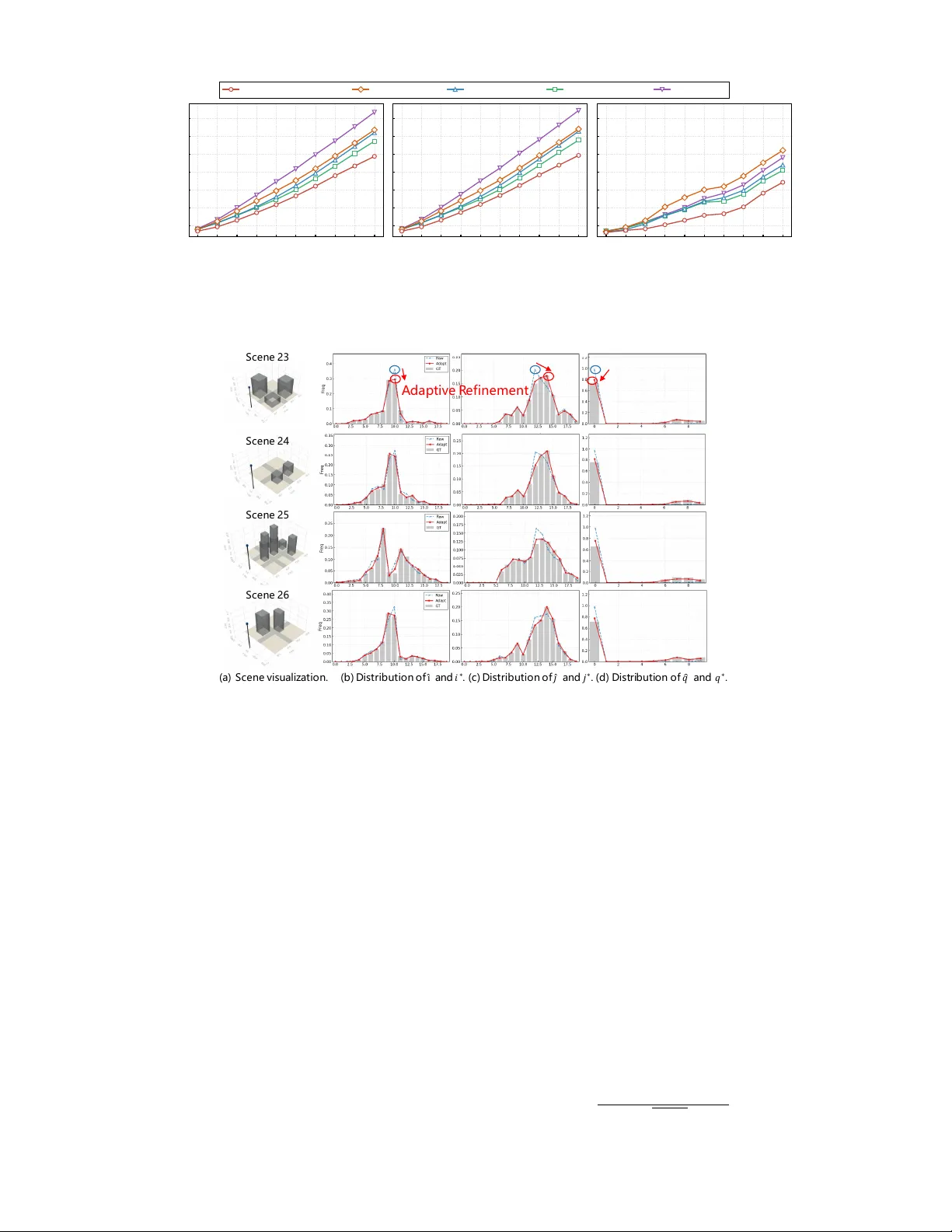
Structure-A ware Multimodal LLM Frame work for T rustw orthy Near-Field Beam Prediction Mengyuan Li, Graduate Student Member , IEEE , Qianfan Lu, Jiachen T ian, Hongjun Hu, Y u Han, Senior Member , IEEE , Xiao Li, Senior Member , IEEE , Chao-Kai W en, F ellow , IEEE , and Shi Jin, F ellow , IEEE Abstract —In near -field extremely lar ge-scale multiple-input multiple-output (XL-MIMO) systems, spherical wav efront pr op- agation expands the traditional beam codebook into the joint angular -distance domain, rendering con ventional beam training prohibiti vely inefficient, especially in complex 3-dimensional (3D) low-altitude en vironments. Furthermore, since near-field beam variations are deeply coupled not only with user positions b ut also with the physical surr oundings, precise beam alignment demands prof ound envir onmental understanding capabilities. T o address this, we propose a large language model (LLM)- driven multimodal framework that fuses historical GPS data, RGB image, LiDAR data, and strategically designed task-specific textual pr ompts. By utilizing the powerful emergent reasoning and generalization capabilities of the LLM, our approach learns complex spatial dynamics to achieve superior en vironmental comprehension. T o mitigate the curse of near -field codebook dimensionality , we design a structure-aware beam prediction head. By decoupling the high-dimensional beam index into independent azimuth, elevation, and distance components, our approach explicitly mirr ors the intrinsic 3D geometry of the near - field codebook, enhancing physical interpretability and effectiv ely guiding the learning pr ocess. Meanwhile, an auxiliary trajectory prediction head acts as a spatial prior to guide the beam sear ch. Furthermore, to ensure trustworthy prediction against model un- certainties, the framework concurr ently outputs confidence scor es to trigger an adaptive r efinement mechanism, balancing beam alignment accuracy and pilot overhead. Extensive evaluations demonstrate that our framework significantly outperforms state- of-the-art deep learning (DL)-based prediction algorithms and efficient near -field beam training baselines in both line-of-sight and non-line-of-sight scenarios, with rigorous ablation studies confirming the effectiveness of each proposed module in the framework. Index T erms —Near -field XL-MIMO, low-altitude, beam pre- diction, multimodal learning, large language models, adaptive refinement, trustworthy prediction. I . I N T RO D U C T I O N E Xtremely large-scale multiple-input multiple-output (XL- MIMO) has emerged as a key technology for sixth- generation (6G) wireless systems [ 1 ]. By equipping the base station (BS) with hundreds or thousands of antennas, XL- MIMO significantly enlarges the array aperture, enabling high spatial resolution and substantial array gain, thereby enhancing M. Li, Q. Lu, J. Tian, H. Hu, Y . Han, X. Li, and S. Jin are with the School of Information Science and Engineering, Southeast University , Nanjing 210096, China (email: mengyuan li@seu.edu.cn; qianfan lu@seu.edu.cn; tianjiachen@seu.edu.cn; huhongjun@seu.edu.cn; hanyu@seu.edu.cn; li xiao@seu.edu.cn; jinshi@seu.edu.cn). C.-K. W en is with the Institute of Communications Engineer- ing, National Sun Y at-sen University , Kaohsiung 804, T aiwan (e-mail: chaokai.wen@mail.nsysu.edu.tw). spectral efficiency and supporting ultra-high data rates and seamless co verage [ 2 , 3 ]. Ho wev er , the enlar ged aperture fundamentally alters the propagation re gime. In near-field XL-MIMO systems, spherical wav efront propagation replaces the con ventional planar-w av e assumption, coupling angular and distance dimensions and producing volumetric beam pat- terns [ 4 ]. As a result, near-field beams become extremely narrow and highly position-sensitive. Although high direc- tivity improv es energy focusing, it also increases sensitivity to misalignment, leading to severe degradation of achiev able rates [ 5 ]. Consequently , efficient beam alignment becomes a structural requirement in near-field XL-MIMO systems. A. Prior W orks Beam management has been extensi vely in vestigated to reduce training overhead while maintaining reliable alignment. Existing works can be broadly classified into two primary paradigms: beam training-based methods and beam prediction- based methods. The former improv es search efficienc y through structured pilot sweeping, whereas the latter aims to di- rectly infer future optimal beams from historical observ ations. More recently , beam prediction has e volv ed to ward multi- modal en vironment-aware learning, incorporating heteroge- neous sensing information to impro ve semantic a wareness and robustness. 1) Beam T raining-Based Methods: Con ventional beam training determines the optimal beam via pilot sweeping. Al- though reliable, exhaustiv e search incurs substantial overhead and suffers from information aging in dynamic scenarios [ 6 ]. Numerous studies hav e therefore proposed structured search strategies to reduce pilot consumption. In far-field systems, various hierarchical and adaptiv e schemes are designed to effecti vely balance beam training ov erhead and accuracy [ 7 – 10 ]. Ho wev er , in near-field XL-MIMO systems, spherical wa vefront propagation introduces an additional distance di- mension, causing e xponential growth of the angular-distance codebook [ 11 , 12 ]. The resulting high-dimensional v olumetric search space significantly increases computational and signal- ing complexity . T o mitigate this issue, hierarchical and multi- stage strategies progressiv ely refine angular and distance esti- mates [ 13 , 14 ]. Other approaches exploit structural properties of beam patterns to reuse far-field discrete Fourier transform codebooks for near-field estimation [ 15 ]. From a probabilistic viewpoint, Bayesian re gression frame works model codew ord correlations to infer optimal beams with limited measure- ments [ 6 ]. Despite these adv ances, beam training remains fundamentally a measurement-driven search procedure. As codebook dimensionality and mobility increase, pilot overhead and latency become increasingly prohibitiv e in practical near- field deployments. 2) W ireless-Only Beam Prediction: T o further reduce on- line search complexity , beam prediction methods aim to fore- cast optimal beams directly from historical wireless obser- vations [ 16 – 21 ]. Early approaches rely on kinematic models and sequential estimation techniques such as the extended Kalman filter and particle filter [ 16 , 17 ]. Howe ver , their reliance on simplified motion assumptions limits robustness under nonlinear mobility and rapid channel variation. W ith the advancement of artificial intelligence, data-driven models have emerged as a dominant paradigm [ 20 , 21 ]. Recurrent neural networks (RNNs) and long short-term memory (LSTM) net- works hav e been widely adopted to learn temporal correlations between historical beams or pilot signals and future optimal beams [ 18 , 19 ]. By formulating beam prediction as a sequence learning problem, these methods effecti vely capture nonlinear temporal dynamics and significantly reduce search overhead. Nev ertheless, most existing prediction approaches rely solely on wireless measurements. In near-field XL-MIMO systems, optimal beam selection is intrinsically coupled with user position and surrounding geometry due to volumetric beam characteristics. The exponential growth of angular- distance codebooks expands the prediction output space be- yond con ventional classification scalability . W ithout explicit geometric and en vironmental semantics, wireless-only models face fundamental generalization limitations. 3) Multimodal Envir onment-A war e Beam Prediction: T o address the lack of environmental awareness, recent studies incorporate heterogeneous sensing modalities such as RGB images, LiD AR point clouds, and GPS data into beam pre- diction frameworks [ 22 – 28 ]. By explicitly modeling scatterer distributions and blockage conditions, multimodal approaches enhance robustness in comple x propagation en vironments. Motiv ated by the success of generative AI, recent works hav e increasingly explored large language models (LLMs) to process multimodal information for beam prediction [ 25 – 28 ]. This paradigm shift is driv en by three intrinsic advan- tages: (i) massive pre-training provides superior generaliza- tion across diverse communication scenarios; (ii) task-specific prompts significantly enhance the model’ s comprehension of customized prediction objecti ves; and (iii) LLMs exhibit ex- ceptional capacity in fitting high-dimensional heterogeneous data. Specifically , MLM-BP [ 25 ] adopts a DeepSeek-based multimodal model [ 29 ] to fit scatterer distributions tokenized by a LoRA-tuned image encoder [ 30 ]. T o capitalize on task- specific prompting, [ 27 ] employs a prompt-as-prefix strategy to encode historical beams and en vironmental states, effec- tiv ely reformulating beam prediction as a language reasoning task to guide the LLM’ s understanding. Building upon these foundational strengths, M2BeamLLM [ 26 ] performs rigorous multimodal feature alignment before LLM inference, fully unlocking the pre-trained model’ s capacity to process and fit different modality features within a unified semantic space. Howe ver , multimodal near-field beam prediction still faces sev eral critical challenges. First, most existing studies still focus on far -field propagation, which is largely restricted by the attrib utes of prev alent benchmarks, such as DeepSense 6G [ 31 ] and Multimodal-W ireless [ 32 ] that are tailored for far -field settings, failing to capture the spherical wav efronts and the unique spatial-selective characteristics in near-field regions. Second, the exponential expansion of joint angular- distance codebooks renders direct codew ord-le vel classifica- tion inefficient and poorly scalable in 3-dimensional (3D) low- altitude en vironments, necessitating the structural exploitation of geometric constraints. Third, current multimodal frame- works prioritize accuracy while overlooking reliability . The absence of confidence assessment and adaptive fallback mech- anisms inevitably leads to unstable system performance in high-mobility scenarios. B. Main Contributions T o address the aforementioned challenges, we propose a structure-aware multimodal LLM framew ork for trustworthy beam prediction in near-field XL-MIMO systems. Specifically , our main contributions are summarized as follo ws: • Multimodal Inputs and LLM Reasoning: W e design tailored encoders to effecti vely extract rich environmental semantics from di verse multimodal inputs. By fusing these representations with proposed task- and trajectory- related te xtual prompts, it provides contextual guidance that empo wers the LLM backbone. This fully unleashes the emergent reasoning capabilities of LLM to achiev e a profound understanding of the environment. Since the optimal near-field beam index is highly coupled with physical spatial geometries, this deep environmental awareness significantly boosts the accuracy . • Structur e-A ware Beam Prediction with A uxiliary T ra- jectory Guidance: T o mitigate the curse of dimension- ality , we utilize a structure-aw are, decoupled prediction strategy . By independently predicting the azimuth, ele va- tion, and distance indices, our approach explicitly mirrors the near-field codebook’ s intrinsic 3D geometry , which effecti vely guides the learning process and significantly boosts prediction accuracy . Furthermore, we introduce an auxiliary trajectory prediction head to capture the U A V’ s future motion dynamics, which acts as a spatial prior to guide the beam search process and to further improv e the accuracy . • Confidence-A ware Adaptive Refinement: T o combat model uncertainties, we propose a confidence-dri ven strategy that dynamically triggers small-scale beam scan- ning within the predicted candidate pool only when the confidence score is low . This mechanism optimally bal- ances pilot ov erhead and highly accurate beam alignment. • Compr ehensive V alidation and Ablation Studies: Ex- tensiv e experiments under both LoS and NLoS conditions demonstrate consistent performance gains over state-of- the-art (SO T A) sequence prediction models and efficient 2 near-field beam training baselines. Furthermore, rigorous ablation studies are conducted to validate the necessity and effecti veness of each core component within the proposed framew ork. Notations. Bold uppercase and lowercase letters denote matrices and vectors, respectively . ( · ) ⊤ and ( · ) H denote trans- pose and conjugate transpose. ⊙ , E {·} , | · | , and ∥ · ∥ repre- sent the Hadamard product, expectation, absolute value, and Euclidean norm, respectiv ely . I denotes the identity matrix. C N represents the complex Gaussian distribution. I ( · ) denotes the indicator function, which equals 1 if the condition holds and 0 otherwise. Finally , clamp( x, a, b ) = max( a, min( x, b )) restricts the value of x to the interv al [ a, b ] . I I . S Y S T E M M O D E L In this section, we first establish the near-field channel and XL-MIMO system models. Building upon these foundations, the beam prediction task is formulated as a sequential multi- modal prediction problem. A. Channel Model W e consider a single-cell XL-MIMO system operating in the urban low-altitude environment, as illustrated in Fig. 1 . The system consists of a BS and a mobile U A V as the user equipment (UE). T o facilitate multi-modal en vironment perception, the BS is equipped with an RGB camera and a LiD AR sensor alongside a uniform planar array (UP A) with M = M y × M z antennas, where M y and M z denote the number of antenna elements along the horizontal and vertical axes, respectiv ely . The antenna element spacing is set as d y = d z = 0 . 5 λ , where λ = c/f c is the wav elength at carrier frequency f c , and c is the speed of light. The position of the m -th antenna element, indexed by ( m y , m z ) , is giv en by p m = o BS + h 0 , m y − M y − 1 2 d y , M z − 1 2 − m z d z i T , (1) where o BS denotes the center of the UP A, m y ∈ { 0 , . . . , M y − 1 } and m z ∈ { 0 , . . . , M z − 1 } . The UA V is assumed to operate within the near-field region. Meanwhile, the U A V is equipped with an onboard GPS recei ver . It is equipped with a single omnidirectional antenna and follo ws a time-varying 3D trajectory , with its instantaneous location at time t denoted by u t ∈ R 3 . W e employ the Sionna ray tracing (R T) [ 33 ] for high-fidelity near-field channel generation. It computes the channel impulse responses by combining shooting-and-bouncing rays (SBR) with the image method, simulating the physical interaction of wav efronts with en vironmental scatterers. The time-varying near-field uplink channel v ector h ( t ) ∈ C M × 1 is composed of the channel response h m ( t ) for each receiv e antenna m . Specifically , h m ( t ) is modeled as: h m ( t ) = L ( t ) X l =1 g l,m ( t ) e − j 2 π λ d l,m ( t ) , (2) where L ( t ) is the number of propagation paths, g l,m ( t ) and d l,m ( t ) represent the complex path gain and the propagation G PS Ca me r a L i d a r U A V BS z x y O M z M y r m p m r θ φ Fig. 1: Illustration of the XL-MIMO system model in LAE scenarios: The BS is equipped with a UP A, an RGB camera, and a LiD AR, while the UA V is equipped with a GPS which feeds back locations to the BS. path length of the l -th path arriving at the m -th antenna, re- spectiv ely . Unlike the far-field plane wav e assumption, the path length d l,m ( t ) is calculated based on the specific propagation topology and the exact Euclidean distance to each antenna element. For the line-of-sight (LoS) path, the distance can be expressed as d l,m ( t ) = ∥ u t − p m ∥ . (3) For non-LoS (NLoS) paths, d l,m ( t ) is geometrically calculated as the sum of physical distances between consecutiv e interac- tion points (e.g., reflections, dif fractions, or scattering). Fur- thermore, the complex gain g l,m ( t ) e xplicitly captures the path loss, antenna polarization matching, and electromagnetic (EM) material properties. Instead of relying on simplified statistical formulations, g l,m ( t ) is deterministically computed using the Sionna ray tracer (R T) [ 33 ], which accurately ev aluates the EM transfer matrices and spatial field patterns along the precise trajectory of each ray . Assuming the U A V transmits pilot symbols with po wer P r , the receiv ed signal vector y ( t ) ∈ C M × 1 at the BS can be expressed by y ( t ) = p P r w H h ( t ) + w H n ( t ) , (4) where w ∈ C M × 1 is the beamforming vector , n ( t ) ∼ C N ( 0 , σ 2 I ) is the additive white Gaussian noise. B. Pr oblem F ormulation W e first construct a polar-domain codebook W by jointly sampling the angular and distance domains: W = w ( θ i , φ j , r q ) | 1 ≤ i ≤ N θ , 1 ≤ j ≤ N φ , 1 ≤ q ≤ N r , (5) where N θ , N φ , and N r denote the number of sampled code- words for the azimuth angle, elev ation angle, and distance, respectiv ely . The near-field code word corresponding to the tuple ( θ i , φ j , r q ) is defined as w ( θ i , φ j , r q ) = 1 √ M e − j 2 π λ ( ∥ p cw − p 1 ∥ ) , . . . , e − j 2 π λ ( ∥ p cw − p M ∥ ) T , (6) 3 where p cw is the Cartesian coordinate of the sampled point. For a selected beam code word w ∈ W at time slot t , the achiev able rate is defined as R ( w , t ) = log 2 1 + P r w H h ( t ) 2 σ 2 ! , (7) where P r is the transmit power and σ 2 is the noise variance. The objectiv e of beam management is to select the optimal codew ord w ⋆ that maximizes ( 7 ), which is equiv alent to maximizing the recei ved beamforming gain. Specifically , we first define the beamforming gain for a giv en codeword w at time slot t as: G ( w , t ) = w H h ( t ) 2 . (8) The optimal code word is then obtained by finding the maxi- mum gain across the codebook: w ⋆ = arg max w ∈W G ( w , t ) . (9) While exhaustiv e beam search guarantees optimal selection, ev aluating the massiv e near-field codebook of size N θ N φ N r incurs prohibitiv ely high training overhead and latenc y . T o bypass the exhaustiv e search ov erhead, we formulate beam training as a sequential prediction task. Instead of relying solely on traditional pilot signals, we design multimodal encoders to extract a unified representation E t that encapsu- lates the en vironmental context from sensing data alongside the UA V’ s kinematic information over a historical window [ t − L h , t ] . Furthermore, predicting a single global beam index ov er the massi ve near-field codebook creates an unwieldy action space that sev erely hinders network conv ergence. T o accelerate the learning process and reduce complexity , we decouple the prediction across the three spatial dimensions. Our objecti ve is to learn a mapping function F Θ ( · ) that directly predicts the optimal decoupled index triplets for a subsequent horizon of length L p : ( ˆ i, ˆ j , ˆ q ) t +1 , . . . , ( ˆ i, ˆ j , ˆ q ) t + L p = F Θ E t , (10) where ( ˆ i, ˆ j , ˆ q ) τ denotes the predicted sub-indices for azimuth, elev ation, and distance, respectiv ely , at future time slot τ ∈ { t + 1 , . . . , t + L p } . T o establish the ground truth for our predictiv e model, we define the optimal sub-indices for azimuth i ⋆ , elev ation j ⋆ , and distance q ⋆ at time slot t by jointly maximizing the beamforming gain: ( i ⋆ , j ⋆ , q ⋆ ) = arg max 1 ≤ i ≤ N θ 1 ≤ j ≤ N φ 1 ≤ q ≤ N r w ( θ i , φ j , r q ) H h ( t ) 2 . (11) The overall optimal beam index k ⋆ ∈ { 1 , . . . , N θ N φ N r } can be uniquely mapped from this triplet via k ⋆ = ( i ⋆ − 1) N φ N r + ( j ⋆ − 1) N r + q ⋆ . (12) I I I . S T RU C T U R E - A WA R E M U LTI M O D A L L L M F R A M E W O R K In this section, we elaborate on the proposed structure- aware LLM-driv en multimodal beam prediction framework. W e first present an overvie w of the proposed framew ork. Then, we detail the core components, including multimodal encoders and the feature fusion module, the structure-aware beam prediction head, and the adapti ve refinement mechanism. Finally , we describe the training scheme and loss function design. A. Overall W orkflow The ov erall workflo w of the proposed framework is shown in Fig. 2 . It adopts a “repr esentation-per ception-fusion- r easoning-refinement” paradigm through the follo wing fiv e modules: 1) Multimodal Input Representation: T o accurately predict the optimal beam index by capturing the complex interplay between the U A V’ s kinematic state and the wireless propa- gation en vironment, we first formulate the multimodal input set X in = {H t , I t , L t , T t } , which integrates complementary information across distinct modalities, including: • Historical Kinematics ( H t ): T o capture the UA V’ s temporal motion trajectory , we construct a sequence of historical positions H t = { u ( τ ) } t τ = t − L h +1 , where u ( τ ) ∈ R N × 1 × 3 denotes the 3D coordinate at time slot τ , acquired via an onboard GPS recei ver and subsequently fed back to the BS. N is the batch size. Specifically , we model the measurement error of GPS by u ( τ ) = ˜ u ( τ ) + n ( τ ) , where ˜ u ( τ ) is the true UA V position and n ( τ ) ∼ N ( 0 , σ 2 GPS I ) represents the additiv e Gaussian noise with standard deviation σ GPS . • V isual and Depth Data ( I t , L t ): T o comprehensiv ely perceiv e the en vironment, both an RGB camera and a Li- D AR are deployed at the BS. The camera provides RGB images I t containing texture and blockage information, whereas the LiDAR generates point clouds L t detailing the precise depth and geometric structure of the scat- tering en vironment. T o av oid the memory ov erhead and processing latency associated with sequence modeling, the proposed scheme relies solely on the instantaneous sensory observations I t and L t at current time slot t . • T extual Prompts ( T t ): T o inject domain knowledge, we construct te xtual prompts T t that encompass static system descriptions (e.g., operating frequency , antenna array size) and dynamic descriptions of the U A V’ s flight mode (e.g., “Zigzag”, “Street Patrol”). These inputs are then fed into their respective encoders to be projected into a unified high-dimensional latent space. 2) Multimodal Encoders and F eatur e Fusion: The frame- work first explicitly models the UA V’ s temporal motion trends by calculating and encoding historical kinematic states from H t . Simultaneously , to effecti vely couple the physical en vi- ronment with the U A V’ s location, we introduce a position- guided attention (PGA) mechanism that extracts position- related features from RGB images and LiDAR point clouds. 4 G P S P o s i t i o n - G u i d e d A t t e n t i o n ( P G A ) L i D A R C l o u d P o i n t L i D A R A t t e n t i o n E n c o d e r P o i n t N e t P G A Q u e r y : C u r r e n t p o s i t i o n K e y / V a l u e : I m a g e f e a t u r e s I m a g e I m a g e A t t e n t i o n E n c o d e r P G A R e s N e t - 18 T e x t u a l P r o m p t T e x t E n c o d e r F r o z e n BE R T L i n e a r M u l t i m o d al F eat u r e F u s i o n G P T2 Ba c k b o n e Bo t t o m L a y e r s ( F r o z e n ) T o p L a y e r s ( T r a i n a b l e ) U A V K i n e m a t i c s E n c o d e r M u l t i m o d al I n p u t s R e p r e s e n t at i o n Q u e r y : P o s i t i o n K e y / V a l u e : I m a g e / L i D AR H i s t o r y t i m e s l o t s L a s t h i s t o r y t i m e s l o t L a s t h i s t o r y t i m e s l o t P r i m a r y S t r u c t u r e - Aw a r e Be a m P r e d i c t i o n H e a d . . . ? No Y e s S c a n f r o m P r e d i c t e d C a n d i d a t e P o o l F i n a l P r e d i c t e d B e a m s Au x i l i a r y T r a j e c t o r y P r e d i c t i o n H e a d S y s t e m D e s c r i p t i o n + T r a j e c t o r y M o d e M u l t i m o d al E n c o d e r s an d F e at u r e F u s i o n LLM - D r i ve n R e as o n i n g C as c ad e d P r e d i c t i o n H e ad A d ap t i ve R e f i n e m e n t L i n e a r K i n em a ti c s C a l c u l a ti o n Fig. 2: Overall workflo w of the proposed structure-a ware LLM-driv en multimodal beam prediction frame work. Furthermore, semantic guidance is incorporated via a tex- tual prompt encoder that processes system and trajectory descriptions. These multimodal feature streams are ultimately synchronized and concatenated within the following fusion module to form a unified input for the subsequent LLM-driv en reasoning backbone. 3) LLM-Driven Reasoning: The fused multimodal features are subsequently passed to a pre-trained GPT -2 model [ 34 ] 1 for fine-tuning and sequential reasoning. Unlike con ventional methods that formulate beam prediction as a static classifica- tion task, the GPT -2 backbone functions as a context-aware reasoning engine. It effecti vely captures the complex dynamic interactions among the U A V’ s flight trajectory , the surrounding en vironmental geometry , and the corresponding optimal beam sequences. In this way , the network can deduce how the relativ e motion between the U A V and physical scatterers (e.g., blockages or reflectors) influences the beam transitions. Ulti- mately , the model establishes a robust spatiotemporal mapping within the latent space, translating historical observations into highly predictiv e latent representations of future states. 4) Cascaded Pr ediction Heads: T o effecti vely map the GPT -2 output latent representations to the corresponding wire- less channel characteristics, we employ a cascaded dual-head architecture, including: • An A uxiliary T rajectory Prediction Head: The latent representations from the LLM are first processed by an auxiliary network to predict the UA V’ s future 3D co- ordinates { b u ( τ ) } L p τ = t +1 . This trajectory prediction serves as an auxiliary geometric prior rather than the ultimate objectiv e. It forces the latent features to encode the kinematic and surrounding en vironment ev olution, acting as a physical anchor to ground the subsequent beam prediction task. • A Primary Structure-A ware Beam Prediction Head: The predicted trajectory is then injected into the primary beam prediction head. By conditioning on the predicted 3D position, the network effecti vely narrows down the 1 The pre-trained weights of the GPT -2 model can be found at https: //huggingface.co/gpt2 . candidate pool, allo wing it to ignore geometrically impos- sible beams and focus solely on en vironmental features consistent with the U A V’ s future location. Furthermore, to mitigate the curse of dimensionality associated with the enormous near-field codebook, the prediction head av oids directly estimating a global beam index ˆ k . Instead, it outputs decoupled sub-indices ( ˆ i, ˆ j , ˆ q ) that independently specify the azimuth, elev ation, and distance components of the 3D near-field beam. By decomposing the spa- tial prediction task, this decoupled scheme acts as a structure-awar e predictor that respects the inherent 3D geometry of the near -field codebook. This structure- aware design endo ws the beam prediction with explicit physical interpretability . By inherently linking the v aria- tions in the decoupled sub-indices to the tar get’ s actual 3D coordinates in the angular and distance domains, the network a voids the opaque nature of a structureless ov erall index. This explicit physical grounding effecti vely guides the learning process, thereby significantly enhanc- ing the prediction accuracy . 5) Adaptive Refinement Mechanism: Despite the ef fective- ness of the proposed network, data-driven predictions inher- ently exhibit a certain degree of uncertainty . T o improve the reliability of beam prediction and guarantee system communi- cation quality with low pilot overhead, we design an adaptiv e refinement mechanism. Upon generating the beam candidates, the mechanism ev aluates the maximum confidence score ˆ s . High-confidence predictions ( ˆ s > s thre ) are accepted immedi- ately for rapid beamforming. In contrast, low-confidence cases ( ˆ s ≤ s thre ) acti vate a targeted refinement process, e xecuting a small-scale beam sweep e xclusi vely among a small-scale beam candidate pool. This selecti ve execution ef fectiv ely mitigates the impact of model uncertainty , ensuring high-precision track- ing while maintaining a significantly lower o verhead compared to exhausti ve sweeping. B. Multimodal Encoders and F eatur e Fusion 1) UA V Kinematics Calculation and Encoding: T o help capture the temporal motion dynamics, we process the U A V’ s kinematic states over a historical observation window of 5 T e x t ua l P ro m p t E nc o d e r I m a g e A t t e n t i o n E nc o d e r L i DA R A t t e n t i o n E nc o d e r U A V K i ne m a t i c s E nc o d e r T e x t t o k e n L i DA R t o k e n I m a g e t o k e n H i s t o r y k i ne m a t i c s t o k e ns … … F ut ure q ue r y t o k e ns … … L e a rn a b l e Q u e r y E m b e d d i ng s Ti m e E m b e d d i n g … … F i n a l I n p u t E m b e d d i n g s Fig. 3: Architecture of the designed multimodal feature fusion module. length L h . The sequence of historical positions is denoted as { u ( τ ) } t τ = t − L h +1 . The velocity v ( τ ) ∈ R N × 1 × 3 and acceleration a ( τ ) ∈ R N × 1 × 3 are calculated by: v ( τ ) = u ( τ ) − u ( τ − 1) ∆ t , a ( τ ) = v ( τ ) − v ( τ − 1) ∆ t , (13) where ∆ t is the sampling interval. By concatenating these deriv ed states, we construct the historical kinematics sequence H t = { [ u ( τ ) , v ( τ ) , a ( τ )] } t τ = t − L h +1 . This sequence is then projected into the latent space via a learnable linear layer to form the kinematic embedding sequence E kin ∈ R N × L p × d model , which captures the trajectory ev olution and serv es as the motion context for the beam predictor . d model is the unified latent dimension. 2) P osition-Guided Image and LiDAR Encoders: T o align the multimodal data with the UA V’ s real-time locations, we in- troduce a PGA mechanism. As illustrated in Fig. 2 and Fig. 3 , this module serves as a bridge, utilizing the UA V’ s position u ( t ) as a spatial query to acti vely aggregate high-dimensional sensory features. The detailed mathematical formulation of the PGA cross-attention mechanism is provided in Appendix A . By explicitly incorporating geometry constraints, the PGA transforms raw inputs into compact, spatially-aw are context tokens E img and E lidar . a) Image Encoder: W e employ a pre-trained ResNet- 18 [ 35 ] to extract environmental features from RGB images, such as building footprints and road topologies. The output is flattened to generate the visual feature map F img ∈ R N × 49 × d in , where d in denotes the input feature dimension of the PGA module. T o construct the visual spatial bias M img ∈ R N × 1 × 49 , we first project the U A V’ s 3D coordinate u ( t ) onto the 2D im- age plane using the camera intrinsic parameters. Subsequently , we compute M img based on the Gaussian distance between the projected point and the recepti ve field center of each of the 49 feature tokens. This creates a “soft attention spotlight, ” ensuring that the model inherently prioritizes visual features physically closer to the U A V . By feeding u ( t ) , F img , and M img into the PGA module, we obtain the final visual context token E img ∈ R N × 1 × d model . b) LiDAR Encoder: Similarly , a PointNet [ 36 ] backbone processes the point cloud to extract global geometric features. F i x e d T e x t ua l P ro m p t S y s t e m De s c ri p t i o n T ra j e c t o r y M o d e “ S y s t e m C h a r a c t e r i s t i c s : O p e r a t i n g w i t h i n t h e R a y l e i g h d i s t a n c e … ” “low - a l t i t u d e p a t h f o l l o w i n g the u r b a n road t o p o l o g y ” T o k e n i z e r F r o z e n B e r t - T i n y ( F e a t u r e E x t r a c t o r ) E x t r a c t C L S t o k e n o u t p u t C a c h e d B E R T E m b e d d in g s I n p u t b a t c h m o d e i d , i . e . , [ 1 , 4 , 9 ] . L o o k U p L i n e a r P r o j e c t i o n L a ye r N o r m a l i z a t i o n F i n a l P r o m p t E m b e d d i n g s F r o z e n T r a i n a b l e D a t a b u f f e r Fig. 4: Architecture of the designed textual prompt encoder and examples of designed textual prompts. W e sample L lidar key feature points to obtain the geometric feature map F lidar ∈ R N × 1024 × d in . The geometric spatial bias M lidar ∈ R N × 1 × 1024 is directly deriv ed from the 3D Euclidean distance between the U A V coordinate u ( t ) and the spatial coordinates of the sampled LiD AR ke ypoints. Guided by this explicit distance bias, the PGA module aggre gates the raw point features F lidar into the geometric conte xt token E lidar ∈ R N × 1 × d model , thereby heavily weighting the immediate structural constraints surrounding the UA V . 3) T e xtual Pr ompt Encoder: As illustrated in Fig. 4 , to efficiently inject high-lev el semantic guidance, we design a rapid-inference textual encoder that operates on a pre-agreed set of flight modes shared between the BS and the U A V . a) T e xtual Pr ompt Construction: T o guide the beam prediction, we construct a structured textual prompt T t by con- catenating two parts: (i) a static System Description defining the communication task and the en vironment; (ii) a dynamic T rajectory Mode specifying the current trajectory character- istics (e.g., straight flight or turns). This textual context T t helps the generative model understand the physical intent behind the numerical trajectory data. The detailed prompts are ex emplified in Fig. 4 . b) Offline Caching and Online Lookup: T o reduce real- time latency , we decouple textual prompt encoding from the online inference loop. The prompt consists of a static System Description and a dynamic T rajectory Mode . Since the trajectory modes fall into predefined categories, we pre- construct all possible prompt combinations of fline. A frozen BER T -Tin y [ 37 ] backbone is then utilized to pre-compute their embeddings via the [CLS] token, which are stored in a lightweight look-up table. During online inference, the system bypasses expensi ve text tokenization and encoding. It directly retriev es the pre-computed embedding using the current tra- jectory mode ID, and projects it via a learnable linear layer to form the global context token E text ∈ R N × 1 × d model . This strategy can significantly reduce computational o verhead. 4) Multimodal F eatur e Fusion Module: As illustrated in Fig. 3 , we construct the input sequence by aligning all modalities into a shared latent space. First, the historical kinematics sequence H t is projected via an MLP to obtain 6 the history token sequence H h ∈ R N × L h × d model , while a set of learnable embeddings Q p ∈ R N × L p × d model serves as placeholders for future prediction. Subsequently , we concate- nate these two motion-related components along the temporal dimension to form the unified trajectory sequence S traj = [ H h , Q p ] ∈ R N × ( L h + L p ) × d model . T o preserv e temporal order, a learnable time embedding E time ∈ R N × ( L h + L p ) × d model is added element-wise to S traj . Finally , this time-aware trajectory sequence is concatenated with the encoded context tokens E text , E img , and E lidar generated by the upstream encoders to form the unified input sequence E in ∈ R N × (3+ L h + L p ) × d model as follows: E in = Concat ( S traj + E time , E img , E lidar , E text ) . (14) This sequence is then fed into the GPT -2 backbone for au- toregressi ve reasoning to produce the output sequence E out ∈ R N × (3+ L h + L p ) × d model . Specifically , we extract the tokens cor- responding to the future positions b Q p ∈ R N × L p × d model to serve as the learned representations for the subsequent beam prediction head. C. Beam Prediction Head As sho wn in Fig. 5 , the output features from the GPT - 2 backbone are fed into two sequential prediction heads: an auxiliary trajectory prediction head and a decoupled near-field beam prediction head. By first utilizing the U A V’ s position to focus attention on the rele vant surrounding en vironment, the model effect iv ely narrows the candidate search space for the optimal beam. a) Auxiliary T rajectory Pr ediction Head: T o facilitate spatial reasoning, we construct an auxiliary network for tra- jectory prediction. This module processes the learned query tokens b Q p via an MLP to regress the future 3D coordinates. The output is the predicted future trajectory sequence, denoted as { b u ( t + τ ) } τ =1 , ··· ,L p ∈ R N × L p × 3 . This predicted trajectory serves as an intermediate result to assist the primary beam pre- diction. By explicitly recovering the UA V’ s future kinematic intent at each time step t + τ , the network provides strong geometric priors, guiding the subsequent beam predictor to focus strictly on physically plausible locations. b) Primary Near-F ield Beam Prediction Head: Predict- ing the optimal beam directly from a massiv e near-field code- book not only suffers from the curse of dimensionality , but also struggles with the periodic abrupt jumps inherent in 1D index labels. Because the 3D spatial parameters ( θ, ϕ, r ) are flattened into a single 1D index sequence, physically adjacent beams frequently correspond to discontinuous index values. This misalignment destroys the intrinsic spatial correlation and motiv ates our design of a decoupled prediction strategy , which predicts the beam indices across each dimension independently to preserve spatial continuity . Specifically , the output generated by the trajectory pre- diction head is passed through a linear projection layer to serve as the input for the beam prediction head. It then branches into three parallel streams to generate the decoupled beam probability distributions and confidence scores for the A u x i l i ar y H ead : T r aj e c t o r y P r e d i c t i o n H e ad P ri m ar y H e ad : Be am P re d i c t i o n H e ad L i n e ar G E L U L i n e ar L i n ear L i n ear G E L U L i n e ar G E L U L i n e ar L i n e ar L i n e ar FFN FFN FFN Be am I n d e x P r e d i c t i o n H e ad C o n f i d e n c e S c o r e P r ed i c t i o n H ead S i g m o id L i n e ar G E L U L i n e ar FFN L ear n ed F u t u r e q u er y t o k e n s O u t p u t t o k e n s Fig. 5: Architecture of the designed beam prediction head. azimuth, elev ation, and distance, respecti vely . The designed beam prediction head includes: • Beam Index Pr ediction Head: A linear classifier maps the refined features to probability distributions over the three decoupled codebook dimensions. T o predict the optimal beams over the future trajectory , the net- work outputs probability sequences denoted as { b p i ( t + τ ) } i =1 , ··· ,N θ τ =1 , ··· ,L p ∈ R N × L p × N θ , { b p j ( t + τ ) } j =1 , ··· ,N φ τ =1 , ··· ,L p ∈ R N × L p × N φ , and { b p q ( t + τ ) } q =1 , ··· ,N r τ =1 , ··· ,L p ∈ R N × L p × N r . F or each future time step t + τ , the final predicted sub-indices for azimuth ˆ i ( t + τ ) , elev ation ˆ j ( t + τ ) , and distance ˆ q ( t + τ ) are obtained by selecting the index with the maximum probability from each respective distribution. • Confidence Score Prediction Head: Simultaneously , a feed-forward network (FFN) predicts confidence scores for the corresponding predictions. The output sequences are { b s i ( t + τ ) } i =1 , ··· ,N θ τ =1 , ··· ,L p ∈ R N × L p × N θ , { b s j ( t + τ ) } j =1 , ··· ,N φ τ =1 , ··· ,L p ∈ R N × L p × N φ , and { b s q ( t + τ ) } q =1 , ··· ,N r τ =1 , ··· ,L p ∈ R N × L p × N r , where v alues are normalized to [0 , 1] via a Sigmoid function to e valuate the reliability at each time step t + τ . This decoupled design not only reduces the output space com- plexity from O ( N r N φ N θ ) to O ( N r + N φ + N θ ) , significantly alleviating the burden of model fitting, but also allows for fine-grained control over the beam prediction accuracy . D. Adaptive Refinement During the inference phase, we implement an adapti ve refinement post-processing strategy to mitigate unreliable pre- dictions. Initially , we ev aluate the confidence scores of the T op-1 predictions across the three decoupled dimensions (i.e., azimuth, elev ation, and distance). If the confidence scores for all three dimensions simultaneously exceed a pre-defined reliability threshold s thre , the T op-1 index combination is deemed reliable and directly output as the final predicted beam. Howe ver , if the confidence score of any dimension falls below s thre , we trigger a localized search within a high- confidence subspace. Specifically , we e xtract the T op-5 indices from the proba- bility distribution of each dimension. The refined joint search 7 space is denoted as Ω p , which consists of 5 3 = 125 candidate combinations. This subspace is sufficiently small for efficient ev aluation but div erse enough to encompass the optimal beam. T o identify the final refined beam indices, the system ev aluates all combinations in Ω p by maximizing their joint probability: ( ˆ i ( t + τ ) , ˆ j ( t + τ ) , ˆ q ( t + τ )) = arg max ( i,j,q ) ∈ Ω p b p i ( t + τ ) · b p j ( t + τ ) · b p q ( t + τ ) . (15) This strategy ensures that when the predicted T op-1 beam is uncertain, the model can also pro vide a highly reliable pool of candidates for efficient beam sweeping, thereby guaranteeing robust prediction performance. E. T raining Scheme and Loss Function Design a) T raining Scheme: T o guarantee the robustness of the proposed framework against potential sensor failures and to systematically inv estigate the network’ s performance across various modality combinations, we implement a flexible mul- timodal training scheme. Specifically , to simulate real-world scenarios where certain sensory inputs might be una vailable, we train the model under the following configurations: • Support for Missing Modalities: Our frame work is designed to inherently support scenarios with incomplete sensory data. If one or more input modalities are missing or corrupted, their corresponding tokens are dynami- cally e xcluded from the input sequence X in , allo wing the model to perform beam prediction using only the av ailable modalities. • P arameter -Efficient Fine-T uning: Instead of updating all parameters of the pre-trained GPT -2, we adopt a partial fine-tuning strategy to prev ent catastrophic forgetting and reduce computational cost. W e freeze the majority of the transformer blocks and only update: (i) the specific projection layers of encoders and heads; (ii) the positional embeddings and LayerNorm parameters; and (iii) the top two Transformer blocks. • Output Selection: W e exclusi vely select the last L p output embeddings, which correspond to the learnable future query tokens Q p . These tokens are designed to aggregate global context for future inference, while the outputs associated with the preceding context and history tokens are discarded. b) Loss Function: The network is optimized end-to-end via the following loss function: L total = λ 1 L traj + λ 2 L beam + λ 3 L conf , (16) where hyperparameters λ 1 , λ 2 , λ 3 balance three losses. The detailed design of the three loss terms is as follows. First, to ensure precise intermediate localization prediction, we adopt the normalized mean square error (NMSE) averaged ov er all future time steps as L traj = 1 L p L p X τ =1 ∥ b u ( t + τ ) − u ( t + τ ) ∥ 2 ∥ u ( t + τ ) ∥ 2 . (17) Second, we employ a soft target loss strategy to tolerate small spatial misalignments and account for the strong spatial correlation inherent in near-field beams. Instead of utilizing a rigid one-hot label, we construct smoothed target distributions p i ( t + τ ) , p j ( t + τ ) , and p q ( t + τ ) for azimuth, elev ation, and distance, respectively , at each future time step t + τ . Specifically , we assign fixed probability v alues, allocating 0 . 6 to the GT beam index and 0 . 1 to each of the four adjacent near - optimal indices, while setting the probabilities of all remaining indices in the codebook to zero. The network is then optimized to minimize the Kullback- Leibler (KL) di ver gence between the soft target distrib utions and the predicted probability distributions: L beam = 1 3 L p L p X τ =1 N θ X i =1 p i ( t + τ ) log p i ( t + τ ) b p i ( t + τ ) + N φ X j =1 p j ( t + τ ) log p j ( t + τ ) b p j ( t + τ ) + N r X q =1 p q ( t + τ ) log p q ( t + τ ) b p q ( t + τ ) ! . (18) Finally , the confidence score prediction is supervised by the mean squared error (MSE). T o ensure that the confidence score for each dimension solely reflects its own prediction accuracy , we employ an isolation strategy for target generation. T o generate the GT confidence score for the azimuth dimension at time t + τ , we isolate the predicted azimuth index ˆ i ( t + τ ) by pairing it with the GT ele vation and distance indices, yielding the codew ord as follows: ˆ w ( t + τ ) = w θ ˆ i ( t + τ ) , φ j ⋆ ( t + τ ) , r q ⋆ ( t + τ ) . (19) Utilizing the beamforming gain function defined in ( 8 ), the target score is computed as: s i ( t + τ ) = clamp G ˆ w ( t + τ ) , t + τ G w ⋆ ( t + τ ) , t + τ , 0 , 1 ! , (20) where w ⋆ ( t + τ ) represents the GT codew ord at the corre- sponding time step. T arget scores for elev ation s j ( t + τ ) and distance s q ( t + τ ) are computed analogously by isolating their respectiv e GT values. The final confidence loss is formulated by expanding the MSE across the three dimensions: L conf = 1 3 L p L p X τ =1 b s i ( t + τ ) − s i ( t + τ ) 2 + b s j ( t + τ ) − s j ( t + τ ) 2 + b s q ( t + τ ) − s q ( t + τ ) 2 ! . (21) I V . E X P E R I M E N TA L R E S U L T S In this section, we first outline implementation details. W e then benchmark the proposed frame work against SOT A baselines, followed by in-depth ablation studies to v alidate the effecti veness of core components. 8 A. Implementation Details 1) Dataset and F ramework: In our experiments, we utilize Multimodal-LAE-XLMIMO 2 , a comprehensive open-source dataset designed for multimodal sensing-aided XL-MIMO wireless communications in lo w-altitude scenarios. The dataset encompasses 30 div erse 3D urban en vironments and contains 10,770 continuous flight trajectories. For each trajectory , tem- porally aligned multi-modal sensory data and wireless channel features are collected over 20 consecutiv e time slots at the sampling interval ∆ t = 0 . 1 s. This rigorous collection process yields a total of 215,400 labeled samples, comprising 201,075 LoS and 14,325 NLoS samples. T o ev aluate the model’ s generalization capabilities, we adopt a scenario-based dataset splitting strategy: 22 scenes are allocated for training, with 4 reserved for v alidation and 4 for testing. Furthermore, to in ves- tigate the model’ s en vironmental understanding capability , we partition the test set into distinct LoS and NLoS subsets. LoS scenarios are e valuated as foundational tasks with weaker envi- ronmental dependency due to direct path visibility . Conv ersely , NLoS scenarios represent highly challenging cases, where the obstruction of direct signal paths necessitates high-fidelity en vironmental perception and complex spatial reasoning. The XL-MIMO system operates at f c = 7 GHz with an M y × M z = 64 × 64 UP A equipped at the BS. The multi- modal inputs consist of RGB images ( 224 × 224 ), LiD AR point clouds ( 1024 points/frame), and GPS coordinates corrupted by Gaussian noise with standard deviation σ GPS = 0 . 5 . The input dimension of PGA module is defined as d in = 256 , and the unified latent dimension d model is set to 768. For temporal modeling, the model utilizes historical observations from the past L h = 10 time steps to predict the trajectory and optimal beams for the subsequent L p = 10 time steps. During the training phase, the proposed framew ork is fine-tuned for 100 epochs with a batch size of N = 32 , and the loss balancing hyperparameters are empirically set to λ 1 = 0 . 2 , λ 2 = 0 . 6 , and λ 3 = 0 . 2 . The codebook resolutions are set to N r = 10 , N φ = 20 , and N θ = 20 . The confidence score threshold of the proposed adaptiv e refinement is set as s thre = 0 . 9 . 2) Evaluation Metrics: T o comprehensi vely assess the per - formance, we ev aluate the prediction accuracy and spectral efficienc y a veraged over the prediction horizon L p . • T op- K Accuracy: This metric measures the probability that GT beam index is included in the set of T op- K pre- dicted candidates. W e ev aluate this at tw o granularities: (i) Decomposed Accuracy : This e valuates the prediction performance of azimuth, elev ation, and distance indepen- dently . The T op-K accuracies for the three dimensions 2 The dataset is publicly available at: https://github .com/Lmyxxn/ Multimodal- NF are defined as: Acc i T op K = 1 L p L p X τ =1 I i ⋆ ( t + τ ) ∈ I T op- K ( t + τ ) , Acc j T op- K = 1 L p L p X τ =1 I j ⋆ ( t + τ ) ∈ J T op- K ( t + τ ) , Acc q T op- K = 1 L p L p X τ =1 I q ⋆ ( t + τ ) ∈ Q T op- K ( t + τ ) , (22) where I top- K , J top- K , and Q top- K denote the sets of K indices with the highest probabilities for azimuth, elev ation, and distance, respecti vely . (ii) joint Accuracy : This e valuates the success of the ov erall beam index tuple prediction. It is defined as: Acc joint top- K = 1 L p L p X τ =1 I k ⋆ ( t + τ ) ∈ Ω top- K ( t + τ ) , (23) where Ω top- K is the candidate set containing the K ov erall indices with the highest joint probabilities. • A verage Achie vable Rate: Follo wing the achiev able rate defined in ( 7 ), the average rate over the prediction horizon is expressed as: R a = 1 L p L p X τ =1 R ˆ w ( t + τ ) , t + τ , (24) where ˆ w ( t + τ ) ∈ W denotes the beam code word constructed from the predicted indices ˆ i ( t + τ ) , ˆ j ( t + τ ) , ˆ q ( t + τ ) at future time step t + τ . • A verage Normalized Beamf orming Gain: This metric ev aluates the gap between the predicted beam and the optimal beam. Using the beamforming gain defined in ( 8 ), the av erage normalized beamforming gain over the pre- diction horizon is calculated as: ¯ G = 1 L p L p X τ =1 G ˆ w ( t + τ ) , t + τ G w ⋆ ( t + τ ) , t + τ . (25) • T rajectory Prediction Mean Absolute Error (MAE) W e e valuate the precision of the intermediate output predicted trajectory utilizing MAE = 1 L p L p X τ =1 ∥ u ( t + τ ) − b u ( t + τ ) ∥ . (26) 3) Baselines and Ablation Studies: T o comprehensi vely ev aluate the proposed framew ork, we benchmark its perfor- mance against two categories of representativ e algorithms and conduct ablation studies to validate our design: • Deep Lear ning (DL)-based Sequence Models: W e first benchmark against lightweight and widely adopted sequence models as baselines, specifically RNN [ 18 ] and LSTM [ 19 ] with history GPS positions as the in- put. Furthermore, we compare our frame work against 9 (a) T op-1 accuracy (b) T op-5 accuracy Fig. 6: Beam prediction accuracy comparison for different deep learning-based algorithms across overall, LoS, and NLoS scenarios. (a) T op-1 accuracy . (b) T op-5 accuracy . M2BeamLLM [ 26 ], a SO T A multi-modal LLM-driven method. • Efficient Near-Field Beam T raining Algorithms: W e also compare against near-field search methods, specifi- cally Hierarchical Search [ 13 ] and T wo-stage Search [ 14 ]. For a fair comparison, the pilot ov erhead for these search- based baselines is strictly limited to match the av erage pilot b udget consumed by our adapti ve refinement phase. • Ablation Studies: W e conduct comprehensi ve ablation studies to e valuate the core contrib utions of our proposed framew ork, structured into two main parts. Part I in vesti- gates the impact of varying combinations of input modal- ities and demonstrates the significant performance gains achiev ed by the proposed adapti ve refinement strategy . Part II assesses the effecti veness of the proposed core components by isolating the LLM backbone, the decou- pled beam index prediction head, the auxiliary trajectory prediction head, and the designed te xtual prompt. B. Beam Prediction P erformance 1) Accuracy Comparison with DL Baselines: As illus- trated in Fig. 6 (a), the proposed frame work without adap- tiv e refinement surpasses all other baselines in all the ac- curacy metrics, including Acc i T op 1 , Acc j T op 1 , Acc q T op 1 , Acc joint T op 1 and Acc i T op 5 , Acc j T op 5 , Acc q T op 5 , Acc joint T op 5 . Moreover , the pro- posed framework with GPS-only inputs achie ves a T op-1 joint accuracy of 35% across all test scenarios. This performance significantly exceeds that of traditional sequence models such as RNN [ 18 ] and LSTM [ 19 ], which struggle to surpass the Fig. 7: Performance comparison of T op-1 beam prediction accuracy against near -field baselines with consistent beam training overhead. 10% threshold given the same input. Notably , it ev en slightly outperforms M2BeamLLM [ 26 ], which utilizes GPS, images, and LiD AR data as the inputs. This superiority mainly stems from the proposed structure-aware beam prediction strategy , which effecti vely simplifies the high-dimensional near-field search space compared to the ov erall beam index classifica- tion approach of M2BeamLLM and uses auxiliary trajectory prediction to further enhance the accuracy . Building upon this superior architecture, the proposed confidence-score-based adaptiv e refinement mechanism further improves the reliability and accuracy of the prediction. Specifically , it boosts the T op-1 joint beam prediction accuracy to 83% across all test scenarios. Even in the most difficult NLoS environments, the refinement mechanism successfully ele vates the accuracy from 18% to 78%, ensuring highly reliable beam alignment where con ventional baselines completely collapse. As sho wn in Fig. 6 (b), the T op-5 joint accuracy of the proposed frame work e xceeds 90% in both LoS and NLoS scenarios, while the accurac y for each decomposed index (azimuth, ele vation, and distance) consistently surpasses 95%, which exceeds other baselines. Such high T op-5 performance validates the reliability of the generated candidate pool, pro- viding a solid foundation for the subsequent adaptiv e refine- ment stage to achieve accurate alignment with lo w o verhead. 2) Accuracy Comparison with Near-F ield Beam T raining Baselines: Since conv entional beam training methods are designed to output the optimal beam index, we first ev aluate the T op-1 joint accurac y Acc joint T op 1 for comparison. Fig. 7 illus- trates the performance attained under a fixed ov erhead of 90, matching the av erage overhead incurred by the proposed adap- tiv e refinement strategy , which operates at a 90% confidence threshold and 71.6% needs to sweep from the candidate pool (pool size = 125). Under this ov erhead budget, con ventional baselines suffer from sev ere under-sampling, yielding at most 26.1% overall accuracy . In contrast, our framew ork achieves a rob ust 82.7% accuracy . Specifically , in LoS scenarios, our method outperforms Hierarchical Search [ 13 ] by 3.1 times. In challenging NLoS scenarios where beam training baselines fundamentally fail, our adapti ve refinement proves critical, 10 Fig. 8: Achiev able rate comparison against baselines and the GT upper bound with consistent beam training overhead. boosting accuracy by 4.3 times o ver the frame work without adaptiv e refinement. 3) System Achie vable Rate Comparison: Fig. 8 compares the system achiev able rate of the proposed framew ork against various baselines and the GT upper bound. Compared to DL-based prediction models (RNN [ 18 ], LSTM [ 19 ], and M2BeamLLM [ 26 ]), our frame work demonstrates superior performance gain across all test scenarios, which is partic- ularly pronounced in NLoS en vironments (Fig. 8 (c)), where the substantial gap between our method and other models underscores the superior en vironmental perception and spatial reasoning capabilities of the proposed frame work. Further- more, when compared to effici ent near-field beam training baselines (Hierarchical [ 13 ] and T wo-stage [ 14 ]) under the same overhead, our approach maintains a near-optimal rate that closely tracks the GT upper bound. In LoS scenarios, our framework outperforms the Hierarchical baseline by a staggering 94%. Finally , the confidence-score-based adaptiv e refinement proves essential for robustness. It brings a 20% and 52% rate gain over the proposed frame work without refinement in LoS and NLoS scenarios, respectiv ely . Notably , in NLoS cases, the adaptiv e mechanism effecti vely bridges the performance gap, achie ving a 78% higher rate than the T wo- stage baseline and ensuring reliable connecti vity in complex en vironments. C. Ablation Study T o ev aluate the ef fectiv eness of the various components of the proposed frame work, we conduct a comprehensi ve ablation study as summarized in T able I . The analysis is di vided into three aspects, including the impact of input modalities, the improv ements brought by the adaptiv e refinement strategy , and the contribution of individual framew ork components. 1) Impact of Input Modalities: As shown in Part I of T able I , the full modalities configuration (GPS+IMG+LiD AR+Prompt) achiev es the best performance across all metrics, yielding the lowest positioning MAE of 0.8959 m and an initial T op-1 accuracy of 43.08% (without adaptiv e refinement). By comparing different modality subsets, it can be observed that the integration of visual semantics and depth information is crucial for spatial awareness. For example, transitioning from “GPS-Only” to the full modalities setup reduces the positioning MAE by 31.7% (1.3117 m to 0.8959 m), introduces a 7.5% T op-1 accuracy gain, and boosts the high confidence ratio from 15.3% to 29.4%. Fig. 9 also presents an ablation study on the proposed auxiliary trajectory prediction head, illustrating the trajectory MAE versus the prediction time step τ under various input modality combinations. The results demonstrate that the proposed frame work achie ves high-precision trajectory tracking concurrently with robust beam prediction. Notably , the full modalities input exhibits superior stability , maintaining the positioning error within a small range of 0.3 m to 1.5 m. In contrast, incomplete configurations suffer from performance de gradation as the prediction horizon extends. This comparison validates that, alongside the dominant positional data, the integration of div erse modalities is indispensable for accurately capturing complex motion dynamics and en vironmental contexts. Notably , T able I shows a lower trajectory prediction MAE in NLoS scenarios compared to LoS. This is largely because NLoS conditions are frequently in low-speed trajectory mode or hovering near blockages. 2) Impr ovements of the Pr oposed Adaptive Refinement: As shown in Part I of T able I , the proposed adaptiv e refinement strategy provides a decisi ve performance leap. In overall test scenarios, it surges the T op-1 accuracy from 43.08% to 82.66%. This impro vement is even more significant in NLoS cases, where the accuracy climbs from 17.84% to 77.75%, demonstrating the framework’ s ability to correct prediction errors through the proposed confidence-score-based adaptiv e refinement. Fig. 10 further compares the predicted beam index distributions of our framework (with and without adaptiv e refinement) against the GT distrib ution across all test scenarios. The histograms denote the GT , while the curves represent the raw and refined predictions. The high degree of ov erlap between the final predictions and the GT demonstrates the robustness of the proposed framework. The result also validates the ef ficacy of the proposed confidence-score-based adaptiv e refinement. While raw predictions without refinement occasionally sho w minor de viations in peak positioning or magnitude caused by inherent model uncertainties, the re- 11 T ABLE I: Performance Comparison and Ablation Study of the Proposed LLM-Dri ven Multi-Modal Framework. Configuration Scenario Pos MAE [m] ↓ T op-1 Acc [%] ↑ T op-5 Acc [%] ↑ Norm. Gain ↑ High Conf. [%] † ↑ Part I: Ablation of Input Modalities Full Modalities w/ Adaptive Refinement Overall 0.8959 82.66 (+39.58) 95.82 0.9462 (+0.2172) 29.4 LoS 0.9032 82.82 (+38.94) 95.90 0.9490 (+0.2052) 30.0 NLoS 0.6675 77.75 (+59.91) 93.43 0.8558 (+0.5923) 13.2 Full Modalities (w/o Adaptive Refinement) Overall 0.8959 43.08 95.82 0.7290 29.4 LoS 0.9032 43.88 95.90 0.7438 30.0 NLoS 0.6675 17.84 93.43 0.2635 13.2 GPS + IMG + Prompt Overall 1.0337 42.47 93.40 0.7130 24.7 LoS 1.0414 43.36 93.49 0.7276 25.5 NLoS 0.7933 14.32 90.75 0.2526 1.5 GPS + LiDAR + Prompt Overall 0.9955 42.47 92.83 0.7123 22.0 LoS 1.0019 43.52 92.94 0.7286 22.6 NLoS 0.7939 9.47 89.43 0.1990 4.0 GPS + Prompt Overall 1.2346 37.93 91.64 0.6485 16.9 LoS 1.2473 38.89 91.81 0.6636 17.4 NLoS 0.8333 7.93 89.29 0.1737 0.0 GPS Only Overall 1.3117 35.58 89.84 0.6201 15.3 LoS 1.3250 36.50 89.95 0.6350 15.8 NLoS 0.8950 6.80 86.40 0.1510 0.0 Part II: Ablation of the Pr oposed Framework Components Full Modalities with LSTM (w/o LLM Backbone) Overall 9.8036 6.70 29.57 0.1396 – LoS 9.9179 6.88 30.32 0.1430 – NLoS 6.2022 1.10 6.17 0.0302 – Full Modalities (w/o Decoupled Head) Overall 1.1500 36.80 90.50 0.6200 22.0 LoS 1.1580 37.60 90.70 0.6350 22.5 NLoS 0.9000 11.80 84.85 0.1510 6.4 Full Modalities (w/o Auxiliary Head) Overall – 38.70 91.99 0.6681 26.0 LoS – 39.45 92.10 0.6825 26.5 NLoS – 15.20 88.50 0.2150 11.4 Full Modalities (w/o T e xtual Prompt) Overall 1.1041 41.80 92.92 0.7144 19.5 LoS 1.1096 42.91 93.00 0.7327 20.0 NLoS 0.9317 6.61 90.31 0.1373 4.4 † High Conf. represents the percentage of predictions with a confidence score exceeding 0.9. finement mechanism effecti vely corrects these discrepancies, resulting in highly accurate beam predictions. 3) Effectiveness of Pr oposed F ramework Components: Part II of T able I v alidates the ef fectiveness of our core architectural designs, including: • LLM Backbone: Replacing the utilized GPT -2 backbone with a con ventional sequence model, i.e., an LSTM with the same structure as [ 19 ], results in a total performance collapse. Specifically , the trajectory prediction MAE in- creases to 9.8036 m and the T op-1 accuracy drops to 6.70%. This underscores the LLM’ s superior capability in processing heterogeneous multi-modal sequences and reasoning and comprehending complex en vironmental mappings. • Decoupled Beam Index Prediction Head: Ablating the proposed decoupled beam prediction head and predict- ing the ov erall beam index directly leads to a se vere performance degradation. Specifically , the Overall T op- 1 accuracy drops to 36.80%, and the NLoS normalized beamforming gain decreases to 0.1510. This demonstrates that decomposing the massiv e near-field codebook space into distance ( r ) and angular ( φ, θ ) dimensions effecti vely mitigates the curse of dimensionality inherent in large- scale classifications and improves the accurac y . • A uxiliary T rajectory Prediction Head: Ablating the proposed auxiliary trajectory prediction head results in a noticeable performance drop, with the T op-1 accuracy decreasing from 43.08% to 38.70%. This demonstrates that trajectory prediction acts as an effecti ve prior to guide beam prediction, thereby elev ating the model’ s understanding of the environment. • T extual Prompt: Ablating the proposed textual prompt degrades overall performance. Notably , it causes a se- vere drop in the NLoS T op-1 accurac y (from 17.84% 12 1 2 3 4 5 6 7 8 9 10 Prediction Time Step τ 0.50 0.75 1.00 1.25 1.50 1.75 2.00 (a) Overall Perfor mance 1 2 3 4 5 6 7 8 9 10 Prediction Time Step τ (b) LoS Scenarios 1 2 3 4 5 6 7 8 9 10 Prediction Time Step τ (c) NLoS Scenarios T rajectory Prediction MAE (m) GPS+IMG+LiDAR+Pr ompt GPS+IMG+LiDAR GPS+IMG+Pr ompt GPS+LiDAR+Prompt GPS+Prompt Fig. 9: Ablation study on the proposed auxiliary trajectory prediction head: T rajectory MAE versus prediction time step τ under various input modality combinations. S c e n e 26 A d a p t i ve R e f i n e m e n t (a ) S c e n e v isu a liz a t io n . (c ) D ist r ib u t io n o f a n d . (b ) D ist r ib u t io n o f a n d . (d ) D is t r i b u t i o n o f a n d . S c e n e 2 5 S c e n e 2 4 S c e n e 2 3 Fig. 10: Comparison of the predicted beam index distributions of the test scenes for the proposed frame work with and without adaptiv e refinement, alongside the GT distribution. to 6.61%) and a significant reduction in the LoS high confidence ratio (from 30.0% to 20.0%). It indicates that the designed te xtual prompts not only secure the pre- diction confidence in LoS scenarios but also provide the indispensable reasoning capability required to overcome complex NLoS blockages. V . C O N C L U S I O N This paper proposed a structure-aware multimodal LLM framew ork to tackle the inherent inef ficiency of near-field XL-MIMO beam training in complex 3D environments. By integrating GPS data, RGB images, and LiD AR data, the proposed frame work le verages the emergent reasoning capa- bilities of LLMs to achieve a profound understanding of the coupling between near -field beams and physical surroundings. T o circumvent the curse of dimensionality in the joint angular- distance domain, we implemented a structure-aware beam prediction strategy that mirrors the 3D geometric structure of the codebook, further enhanced by an auxiliary trajectory prediction head for spatial guidance. Moreover , a trustworthy adaptiv e refinement mechanism was introduced to dynami- cally trigger small-scale scanning based on confidence scores, achieving the trade-of f between alignment accuracy and pilot ov erhead. Extensi ve e xperimental results demonstrate that our framew ork significantly outperforms state-of-the-art baselines in both LoS and NLoS scenarios, underscoring the potential of multimodal LLMs for reliable near-field communications in 6G and beyond. A P P E N D I X A P O S I T I O N - G U I D E D A G G R E G A T I O N M E C H A N I S M The PGA module operates via a cross-attention mechanism. For a given sensory modality , it treats the UA V position u ( t ) ∈ R N × 1 × 3 as the query , and the raw feature map F ∈ R N × N token × d in as both the ke y and value. The aggregation is formulated as: E = Softmax ( u ( t ) W Q )( FW K ) T √ d model + M ( FW V ) , (27) 13 where W Q ∈ R 3 × d model and W K , W V ∈ R d in × d model are learnable projections. The term M ∈ R N × 1 × N token is the spatial bias matrix, and d model is the unified latent dimension. The resulting context token is E ∈ R N × 1 × d model . R E F E R E N C E S [1] Z. W ang et al. , “ A tutorial on extremely large-scale MIMO for 6G: Fundamentals, signal processing, and applications, ” IEEE Commun. Surv . T ut. , vol. 26, no. 3, pp. 1560–1605, Jul. 2024. [2] Y . Han et al. , “T ow ard extra large-scale MIMO: Ne w channel properties and low-cost designs, ” IEEE Internet Things J. , vol. 10, no. 16, pp. 14 569–14 594, Aug. 2023. [3] Y . Liu et al. , “Near-field communications: A comprehensiv e surve y , ” IEEE Commun. Surv . T ut. , vol. 27, no. 3, pp. 1687– 1728, Jun. 2025. [4] M. Cui and L. Dai, “Channel estimation for extremely lar ge- scale MIMO: F ar-field or near-field?” IEEE T rans. Commun. , vol. 70, no. 4, pp. 2663–2677, Apr . 2022. [5] J. Luo et al. , “Efficient hybrid near- and far-field beam training for XL-MIMO communications, ” IEEE T rans. V eh. T ec hnol. , vol. 73, no. 12, pp. 19 785–19 790, Dec. 2024. [6] Z. Xu et al. , “Near-optimal near-field beam training: From searching to inference, ” IEEE T rans. W ir eless Commun. , vol. 24, no. 11, pp. 9173–9185, No v . 2025. [7] H. S. Ghadikolaei et al. , “Beam-searching and transmission scheduling in millimeter wav e communications, ” in Pr oc. IEEE Int. Conf. Commun. (ICC) , Jun. 2015, pp. 1292–1297. [8] Y . Y aman and P . Spasoje vic, “Reducing the LOS ray beam- forming setup time for IEEE 802.11ad and IEEE 802.15.3c, ” in Pr oc. IEEE Mil. Commun. Conf. (MILCOM) , Nov . 2016, pp. 448–453. [9] L.-H. Shen et al. , “Mobility-a ware fast beam training scheme for IEEE 802.11ad/ay wireless systems, ” in Pr oc. IEEE W ireless Commun. Netw . Conf . (WCNC) , Apr . 2018, pp. 1–6. [10] C. Qi et al. , “Hierarchical codebook-based multiuser beam training for millimeter wa ve massiv e MIMO, ” IEEE T rans. W ireless Commun. , vol. 19, no. 12, pp. 8142–8152, Dec. 2020. [11] M. Cui and L. Dai, “Near-field wideband channel estimation for extremely large-scale MIMO, ” Sci. China Inf. Sci. , vol. 66, no. 7, p. 172303, Jun. 2023. [12] M. Li et al. , “Ke ypoint detection empowered near -field user localization and channel reconstruction, ” IEEE T rans. W ir eless Commun. , vol. 24, no. 7, pp. 5664–5677, Jul. 2025. [13] Y . Lu et al. , “Hierarchical beam training for extremely large- scale MIMO: From far-field to near-field, ” IEEE T rans. Com- mun. , vol. 72, no. 4, pp. 2247–2259, Apr . 2024. [14] C. W u et al. , “T wo-stage hierarchical beam training for near- field communications, ” IEEE T rans. V eh. T echnol. , vol. 73, no. 2, pp. 2032–2044, Feb . 2024. [15] X. Wu et al. , “Near-field beam training with DFT codebook, ” in Proc. IEEE W ir eless Commun. Netw . Conf. (WCNC) , Dubai, United Arab Emirates, Apr . 2024, pp. 1–6. [16] L. Chen et al. , “Mmwa ve beam tracking with spatial information based on extended kalman filter , ” IEEE W ir eless Commun. Lett. , vol. 12, no. 4, pp. 615–619, Apr . 2023. [17] S. Jayaprakasam et al. , “Robust beam-tracking for mmwave mobile communications, ” IEEE Commun. Lett. , vol. 21, no. 12, pp. 2654–2657, Dec. 2017. [18] S. Khunteta and A. K. R. Chavva, “Recurrent neural network based beam prediction for millimeter-wa ve 5G systems, ” in Pr oc. IEEE W ireless Commun. Netw . Conf . (WCNC) , Mar . 2021, pp. 1–6. [19] S. H. A. Shah and S. Rangan, “Multi-cell multi-beam prediction using auto-encoder LSTM for mmwa ve systems, ” IEEE T rans. W ireless Commun. , v ol. 21, no. 12, pp. 10 366–10 380, Dec. 2022. [20] X. Lin, “The bridge toward 6G: 5G-Advanced ev olution in 3GPP release 19, ” IEEE Commun. Standard Mag. , vol. 9, no. 1, pp. 28–35, Mar . 2025. [21] Q. Xue et al. , “AI/ML for beam management in 5G-Advanced: A standardization perspective, ” IEEE V eh. T echnol. Mag. , vol. 19, no. 4, pp. 64–72, Dec. 2024. [22] G. Charan et al. , “V ision-position multi-modal beam prediction using real millimeter wa ve datasets, ” in Pr oc. IEEE W ir eless Commun. Netw . Conf. (WCNC) , Austin, TX, USA, Apr . 2022, pp. 2727–2731. [23] ——, “Camera based mmwave beam prediction: T o wards multi- candidate real-world scenarios, ” IEEE T rans. V eh. T echnol. , vol. 74, no. 4, pp. 5897–5913, Apr . 2024. [24] S. Jiang et al. , “LiD AR aided future beam prediction in real- world millimeter wav e V2I communications, ” IEEE W ireless Commun. Lett. , v ol. 12, no. 2, pp. 212–216, Feb . 2023. [25] Y . Zhao et al. , “Multi-modal large models based beam pre- diction: An example empowered by DeepSeek, ” arXiv preprint arXiv:2506.05921 , 2025. [26] C. Zheng et al. , “M2BeamLLM: Multimodal sensing- empowered mmwa ve beam prediction with large language mod- els, ” arXiv pr eprint arXiv:2506.14532 , 2025. [27] Y . Sheng et al. , “Beam prediction based on large language models, ” IEEE W ir eless Commun. Lett. , v ol. 14, no. 5, pp. 1406– 1410, May 2025. [28] W . Liu et al. , “Large-model AI for near field beam prediction: A CNN-GPT2 framework for 6G XL-MIMO, ” arXiv pr eprint arXiv:2510.22557 , Oct. 2025. [29] X. Chen et al. , “Janus-Pro: Unified multimodal understanding and generation with data and model scaling, ” arXiv pr eprint arXiv:2501.17811 , 2025. [30] E. J. Hu et al. , “LoRA: Lo w-rank adaptation of large language models, ” in Pr oc. Int. Conf. Learn. Represent. (ICLR) , 2022. [31] A. Alkhateeb et al. , “DeepSense 6G: A large-scale real-world multi-modal sensing and communication dataset, ” IEEE Com- mun. Mag . , vol. 61, no. 9, pp. 122–128, Sept. 2023. [32] T . Mao et al. , “Multimodal-W ireless: A large-scale dataset for sensing and communication, ” arXiv pr eprint arXiv:2511.03220 , 2025. [33] J. Hoydis et al. , “Sionna R T: Differentiable ray tracing for radio propagation modeling, ” in Proc. IEEE Globecom W orkshops (GC Wkshps) , Kuala Lumpur , Malaysia, Dec. 2023, pp. 317– 321. [34] A. Radford et al. , “Language models are unsupervised multitask learners, ” OpenAI blog , vol. 1, no. 8, p. 9, 2019. [35] K. He et al. , “Deep residual learning for image recognition, ” in Pr oc. IEEE CVPR , Las V egas, NV , USA, Jun. 2016, pp. 770– 778. [36] C. Qi et al. , “PointNet: Deep learning on point sets for 3D clas- sification and segmentation, ” in Pr oc. IEEE CVPR , Honolulu, HI, USA, Jul. 2017, pp. 652–660. [37] J. Devlin et al. , “BER T: Pre-training of deep bidirectional transformers for language understanding, ” in Pr oc. NAA CL- HLT , Minneapolis, MN, USA, Jun. 2019, pp. 4171–4186. 14
Original Paper
Loading high-quality paper...
Comments & Academic Discussion
Loading comments...
Leave a Comment