Low-complexity tuning of pinching-antenna systems for integrated sensing and communication
Pinching antenna systems (PASSs) can dynamically adapt their transmit and receive arrays for sensing and communication in wireless systems. This work explores the potential of PASSs for integrated sensing and communication (ISAC) by proposing a novel…
Authors: Saba Asaad, Chongjun Ouyang, Zhiguo Ding
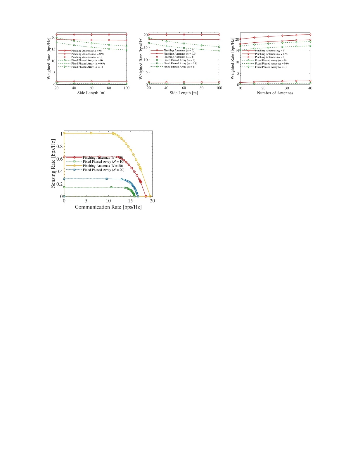
Lo w-Comple xity T uning of Pinching-Antenna Systems for Inte grated Sensing and Communication Saba Asaad Univ ersity of T oronto saba.asaad@utoronto.ca Chongjun Ouyang Queen Mary Uni versity of London c.ouyang@qmul.ac.uk Zhiguo Ding Nanyang T echnological Univ ersity zhiguo.ding@ntu.edu.sg Ali Bereyhi Univ ersity of T oronto ali.bereyhi@utoronto.ca Abstract —Pinching antenna systems (P ASSs) can dynamically adapt their transmit and recei ve arrays f or sensing and com- munication in wireless systems. This work explores the potential of P ASSs f or integrated sensing and communication (ISA C) by proposing a novel P ASS-aided ISA C design, in which pinching locations are adaptively adjusted to enable simultaneous sensing and data transmission with minimal interference. The proposed design introduces a bi-partitioning strategy that allocates sensing power and tunes pinching locations with remarkably lo w com- putational complexity , allowing dynamic P ASS tuning at high update rates. Numerical results demonstrate that the proposed approach achie ves a significantly larger sensing-communication rate region compared to baseline designs at no noticeable cost. I . I N T RO D U C T I O N The recently proposed pinching antenna system (P ASS) has emerged as a promising solution to ov ercome the limitations of traditional antenna arrays in dynamic wireless en vironments [1]–[3]. By allowing electromagnetic w a ves to propagate within a lo w-loss dielectric wa ve guide and radiate through tunable pinching elements, P ASS introduces a flexible ana- log front-end, which can adapti vely reconfigure the radiation pattern [4]–[6]. This reconfigurability enables the system to effecti vely suppress large-scale fading and establish strong line-of-sight (LoS) links, making P ASS particularly attracti ve for medium size indoor communication scenarios [7]. Giv en its flexibility , P ASS naturally aligns with the objec- tiv es considered in integrated sensing and communications (ISA C) systems [8]. In ISA C systems, transmit and recei ve arrays simultaneously exchange data and sensing signals, which often interfere. The ability of P ASS to dynamically adjust the locations of its pinching elements of fers a significant degree of freedom to spatially decouple sensing and com- munication channels, and thereby efficiently mitigating their mutual interference [9]. Se veral recent studies ha ve analyzed this potential, reporting performance bounds that highlight substantial gains of P ASS-aided ISA C architectures. The stud- ies in [9] and [10] characterize the sensing-communication rate region with P ASS transceiv er , reporting a drastic expansion of the rate region under optimal P ASS update. The work in [11] deploys P ASSs to boost the illumination power of the sensing signals in ISAC systems, while guaranteeing a threshold communication Quality-of-Service (QoS). Although these lines of work elaborate the potential of P ASS-aided trans- mission for ISA C, their reported result remains idealistic, as This w ork w as supported in part by German Research F oundation (DFG). they consider optimal tuning of the pinching locations on the transmit and recei ve wav eguides. In practice, the realization of such potentials requires dynamic reconfiguration of the P ASS structure at rates comparable to the channel coherence [12]. This presents a challenge: designing a fast tuning algorithm that adjusts pinching locations rapidly while maintaining the enhanced performance. This work addresses this challenge by dev eloping lo w-complexity algorithms for P ASS-aided ISA C. Contributions: In this paper , we dev elop a lo w- complexity bi-partitioning method for fast dynamic recon- figuration of P ASSs, when deployed for joint sensing and communication in ISAC systems. The proposed method uses the geometry of the cov erage area to partition the pinch- ing elements into communication-centric and sensing-centric elements, and finds the optimal group-sizes by solving a reduced scalar optimization problem. The key contributions in this work are three-fold: ( i ) W e formulate the P ASS- aided ISAC design task in both uplink and downlink cases as a multi-objectiv e optimization problem, which dynamically adjusts the transmit and receiv e pinching locations for optimal trade-off between the spectral efficienc y and sensing rate. ( ii ) W e develop low-complexity algorithms for joint po wer allocation and location tuning in both do wnlink and uplink scenarios. The proposed algorithms optimize the pinching locations in a single step, i.e., with fix ed complexity O (1) , using a geometric approach that optimally splits the pinching elements into communication- and sensing-centric partitions. The former partition is mainly responsible for reconfiguring the communication channel while the latter adjusts the sensing en vironment. W e refer to this technique as bi-partitioning method. ( iii ) W e v alidate our design through numerical ex- periments, comparing the proposed P ASS-aided ISAC design against the fixed-antenna baseline. Our in vestigation depicts that the proposed scheme can significantly enlarge the sensing- communication rate re gion as compared with baseline, while maintaining negligible computational cost. The results suggest that P ASS-aided front-end can significantly enhance perfor- mance of multi-functional wireless systems. Notation: W e show the scalars, vectors, and matrices with non-bold, bold lo wercase, and bold uppercase letters, respectiv ely . Expectation is denoted by E {·} , and the integer sets { 1 , . . . , n } and { n, . . . , m } are shortened as [ n ] and [ n : m ] , respecti vely . I I . S Y S T E M M O D E L A N D P RO B L E M F O R M U L A T I O N Consider two dielectric wave guides extended over the x - axis at altitude a . Each wa ve guide is equipped with multiple pinching elements that can freely mov e across the x -axis. The wa ve guides are distanced d on the y -axis with the first one be- ing located at y = 0 and the other at y = d . For simplicity , we refer to the first wa veguide as the transmit P ASS and the other as receive P ASS in the sequel. The transmit and receiv e P ASSs are equipped with N and M pinching elements, respecti vely . The coordinate of the pinching element n in the transmit P ASS is giv en by v tx ( ℓ tx n ) = [ ℓ tx n , 0 , a ] , and the coordinate of the element m on the recei ve P ASS is v rx ( ℓ rx m ) = [ ℓ rx m , d, a ] , where 0 ≤ ℓ tx n ≤ L tx and 0 ≤ ℓ rx m ≤ L rx with L tx and L rx being the length of the transmit and receive wa ve guides, respectiv ely . The access point (AP) aims to deploy the transmit-recei ve P ASS pair to transmit communication signals to single-antenna users located at u u = [ x u , y u , 0] and sense a tar get located at u t = [ x t , y t , z t ] . The user and target are located, such that a LoS is a vailable between them and the P ASSs. A. Downlink P ASS-ISA C W e first consider do wnlink P ASS, in which the AP transmits information signal to the user and senses the target from its reflection. Let T denote the length of the time frame. At time t ∈ [ T ] , the AP sends the signal x [ t ] to the user . W e consider symbol-lev el a verage transmit po wer constraint, i.e., 1 T T X t =1 E n | x [ t ] | 2 o ≤ P max , (1) for some maximum transmit power P max . Assuming er godic- ity , we can write the constraint as E n | x [ t ] | 2 o ≤ P max . The signal recei ved by the user at time t is then gi ven by y u [ t ] = X n g tx ℓ tx n , u u x [ t ] + ε [ t ] , (2) where ε [ t ] is additiv e white Gaussian noise (A WGN) with zero mean and variance σ 2 u , and g tx ( ℓ, u ) is the ef fectiv e channel from the transmit P ASS through an element at location ℓ to a receiv er at coordinate u and is giv en by g tx ( ℓ, u ) = β exp {− j κ ( D tx ( ℓ, u ) + i ref ℓ ) } √ N D tx ( ℓ, u ) . (3) Here, β captures the effecti ve surface of the pinching element and shadowing, i ref is the reflectiv e index of the wav eguide, κ = 2 π /λ is the wavenumber at wav elength λ , and D tx ( ℓ, u ) denotes the distance between location ℓ on the transmit wav eg- uide and coordinate u , i.e., D tx ( ℓ, u ) = ∥ v tx ( ℓ ) − u ∥ . F or the sake of compactness, we define G tx l tx , u = X n g tx ℓ tx n , u . (4) In practice, user reflections are canceled, since users are re g- istered units. The recei ved signal contains unknown reflections from the tar get and can be written as r [ t ] = ξ t G ( l tx , l rx , u t ) x [ t ] + ν [ t ] , (5) where ν [ t ] is zero-mean A WGN with variance σ 2 rx , d , and the scalar ξ t is the unknown radar cross-section (RCS). Follo wing the Swerling-I model, we assume the RCS is relatively con- stant from pulse-to-pulse with an a prior Rayleigh distributed amplitude. As a result, ξ t is modeled as a complex zero- mean Gaussian random variable with variance ρ 2 t . In (5), the e xpresison G ( l tx , l rx , u ) is further the transmit-to-recei ve P ASS channel through a tar get at u defined as G ( l tx , l rx , u ) = X m X n g tx ℓ tx n , u g rx ( ℓ rx m , u ) (6a) = G tx l tx , u G rx ( l rx , u ) , (6b) with g rx ( ℓ, u ) denoting the channel from an emitting target at point u to the receiv e P ASS through an element located at ℓ on the recei ve wav eguide and is gi ven by g rx ( ℓ, u ) = β exp {− j κ ( D rx ( ℓ, u ) + i ref ℓ ) } D rx ( ℓ, u ) , (7) for D rx ( ℓ, u ) = ∥ v rx ( ℓ ) − u ∥ and G rx ( l rx , u ) = X m g rx ( ℓ rx m , u ) . (8) B. Uplink P ASS-ISA C In uplink ISA C, the user transmits its information signal x [ t ] to the AP, and the AP broadcasts the sensing signal z [ t ] via its transmit P ASS, where the transmit po wer of the user and the AP are limited by P c and P s , respectively . The sensing signal is reflected by the tar get. In v oking the channel reciprocity and considering perfect cancellation of user reflections, the receiv ed signal by the AP is giv en by y ap [ t ] = G rx ( l rx , u u ) x [ t ] + ξ t G ( l tx , l rx m , u t ) z [ t ] + η [ t ] , (9) for η [ t ] ∼ C N 0 , σ 2 rx , u . The AP utilizes y ap [ t ] to decode the transmitted information and estimate the target parameter ξ t . I I I . C O M M U N I C A T I O N A N D S E N S I N G M E T R I C S W e no w formulate the P ASS-aided ISA C design using the notions of spectral efficiency and sensing mutual information (SMI) [13], [14]. A. Downlink ISA C In downlink ISA C, the spectral efficiency is giv en by R d c l tx , P = log 1 + P σ 2 u G tx ( l tx , u u ) 2 (10) where P = E n | x [ t ] | 2 o ≤ P max . For sensing, the AP estimates target parameter ξ t from its receiv ed reflections r [1] , . . . , r [ T ] . The SMI is defined as I s = 1 T I r ; ξ t | u t , x , (11) where r = [ r [1] , . . . , r [ T ]] T collects reflected samples receiv ed at AP, and x = [ x [1] , . . . , x [ T ]] T is the downlink w av eform. This metric measures the rate of sensing information collected from the en vironment, provided that kno wledge on the transmit signal and target location is available, i.e., the target is tracked. T o compute the SMI, we first write I r ; ξ t | u t , x = h r | u t , x − h r | ξ t , u t , x . (12) Considering (5), we can use the Gaussianty of noise to write h r | ξ t , u t , x = T log 2 π eσ 2 rx , d . (13) W e next write h ( r | u , x ) = Z h r | x = x 0 , u t p tx ( x 0 ) d x 0 , (14) where p tx ( x ) is the distribution of x , and u t is known. For x = x 0 , r is zero-mean complex Gaussian with cov ariance Σ = σ 2 rx , d I T + ρ 2 t G ( l tx , l rx , u ) 2 xx H . (15) W ith standard lines for deri vation, we can conclude I s = 1 T E x ( log 1 + ρ 2 t σ 2 rx , d G ( l tx , l rx , u t ) 2 ∥ x ∥ 2 !) . (16) The exact expression for the SMI depends on p tx ( x ) . T o deriv e a distrib ution-agnostic term, we use Jensen’ s inequality to ev aluate a univ ersal upper -bound as I s ≤ 1 T ( log 1 + ρ 2 t σ 2 rx , d G ( l tx , l rx , u t ) 2 E n ∥ x ∥ 2 o ! ) . (17) Since E n ∥ x ∥ 2 o = T P , we hav e I s ≤ I d s ( l tx , l rx , P ) with I d s l tx , l rx , P = 1 T ( log 1 + ρ 2 t T P σ 2 rx , d G ( l tx , l rx , u t ) 2 !) . (18) W e consider the bound I d s ( l tx , l rx , P ) as the sensing metric. Downlink Design Pr oblem: The design problem in this case is characterized by the following multi-objecti ve optimization max l tx , l rx ,P R d c l tx , P , I d s l tx , l rx , P ( P d ) s.t. P ≤ P max , l tx ∈ L tx , l rx ∈ L rx , where the feasible sets L tx and L rx are defined as L tx = ℓ tx n : 0 ≤ ℓ tx n ≤ L tx and ℓ tx n − ℓ tx n − 1 ≥ ∆ , (19a) L rx = ℓ rx m : 0 ≤ ℓ rx m ≤ L rx and ℓ rx m − ℓ rx m − 1 ≥ ∆ , (19b) for some minimum spacing threshold ∆ . B. Uplink ISA C In uplink ISAC, the sensing and communication signals interfere ov er-the-air . The AP uses successi ve interference can- cellation (SIC): it first decodes the communication signal while treating the sensing signal as noise. The spectral ef ficiency is hence given by R u c l tx , l rx , P c , P s = log 1 + | G rx ( l rx , u u ) | 2 P c ρ 2 t | G ( l tx , l rx , u t ) | 2 P s + σ 2 rx , u ! , (20) where P c = E n | x [ t ] | 2 o and P s = E n | z [ t ] | 2 o . After decoding the information signal, the AP cancels its impact by subtracting it from the received signal. Assuming negligible decoding error , the sufficient statistics computed after interference cancellation is giv en by ˆ y ap [ t ] = y ap [ t ] − G rx ( l rx , u u ) s [ t ] (21a) = ξ t G l tx , l rx , u t z [ t ] + ν [ t ] . (21b) Follo wing the same lines of deri v ations as in downlink sce- nario, the SMI is deriv ed as I s = 1 T E z log 1 + ρ 2 t σ 2 rx , u G ( l tx , l rx , u t ) 2 ∥ z ∥ 2 , (22) where z = [ z [1] , . . . , z [ T ]] . Using Jensen’ s inequality , the SMI can be bounded from above by I u s ( l tx , l rx , P s ) , where I u s l tx , l rx , P s = 1 T log 1 + ρ 2 t σ 2 rx , u G ( l tx , l rx , u t ) 2 T P s . (23) Uplink Design Pr oblem: The design problem in this case is max l tx , l rx ,P s ,P c R u c l tx , l rx , P c , P s , I u s l tx , l rx , P s ( P u ) s.t. P s ≤ P max s , P c ≤ P max c , l tx ∈ L tx , l rx ∈ L rx , for L tx and L rx defined in (19). I V . I S A C S Y S T E M D E S I G N The optimal design is giv en by the P areto front of the multi- objectiv e optimization, whose characterization is not tractable. W e de velop an algorithm to approximate the Pareto front. A. P ASS Design for Downlink ISA C Noting that both communication and sensing metrics are increasing in P , we can conclude that for any point in the Pareto front the optimal P ⋆ = P max . One can further use the monotonic behavior of the logarithm function and re write the downlink design problem in ( P d ) as max l tx , l rx n G tx ( l tx , u u ) 2 , G ( l tx , l rx , u t ) 2 o (24) s.t. l tx ∈ L tx , l rx ∈ L rx . Noting that the reflection channel decomposes as G ( l tx , l rx , u t ) 2 = G tx l tx , u t 2 G rx l rx , u t 2 , (25) we can decouple (24) into tw o marginal problems: a recei ver design problem, which solv es the single-objectiv e optimization max l rx G rx l rx , u t 2 s.t. l rx ∈ L rx , (26) and a transmit design problem which solves max l tx ∈ L tx n G tx ( l tx , u u ) 2 , G tx l tx , u t 2 o . (27) Receive P ASS Design: For (26), it is straightforward to find the solution geometrically . In fact, optimal l rx should hav e the minimum distance to the target and result in in- phase superposition of all signals received by the pinching elements. W ithout spacing restriction, both these conditions are satisfied by setting all elements at x t . Considering the min- imum distance constraint, this can be ef ficiently approximated by distancing the elements by the minimum multiply of the wa ve guide that is larger than the minimum spacing threshold ∆ . Assuming that ∆ ≤ λ , we can approximate accurately the solution of (26) by setting l rx = l rx ⋆ , where ℓ rx m,⋆ = x t + m − M + 1 2 λ. (28) Here, we set a mass center at x t and place the elements sym- metrically around it with ev ery two neighbors distanced λ . Algorithm 1 Do wnlink ISA C-P ASS Design 1: Choose ( ω 1 , ω 2 ) for a sensing-communication trade-off 2: Set pinching locations at the recei ve P ASS to (28) 3: Set α ⋆ ← argmax 0 ≤ α ≤ 1 F ( α ) and N 1 = ⌊ N α ⋆ ⌋ 4: Set pinching locations at the transmit P ASS to (34) 5: return l rx , l tx , and P = P max T ransmit P ASS Design: T o solv e the multi-objectiv e prob- lem in (27), we in v oke the scalarization scheme, in which we optimize a weighted sum of the objectives. This means that we find a Pareto optimal solution by setting max l tx ∈ L tx ω 1 G tx ( l tx , u u ) 2 + ω 2 G tx l tx , u t 2 . (29) Unlike the receiv e P ASS design, the transmit pinching loca- tions should maximize the sum channel gain to the user and to the target. The exact solution is not straightforward; howe ver , it can be efficiently approximated by a simple geometric trick, which we refer to as bi-partitioning tric k in the sequel. Bi-P artitioning T ric k: W e di vide transmit pinching elements into two sets: a set with N 1 elements and the other with N − N 1 elements. W e center the first part close to the user , i.e. uniformly around a mass center at x u with spacing λ , and the second part close to the target, i.e. uniformly around x t with spacing λ . Assuming that elements in each part are spaced for in-phase superimposition at both user and tar get, we ha ve G tx ( l tx , u u ) 2 ≈ β N N 1 N D u , 1 ζ 1 u + N − N 1 N D u , 2 ζ 2 u 2 , (30) where D u , 1 = D tx ( x u , u u ) ≤ D u , 2 = D tx ( x t , u u ) and ζ 1 u and ζ 2 u capture phase-shifts of first and second set, respecti vely . Defining α = N 1 / N as the ratio of elements serving the user and ζ u = ζ 2 u /ζ 1 u as the phase-shift dif ference, we can write G tx ( l tx , u u ) 2 ≈ β N α D u , 1 + 1 − α D u , 2 ζ u 2 . (31) Similarly , we can approximate | G tx ( l tx , u t ) | 2 as G tx ( l tx , u t ) 2 ≈ β N α D t , 2 ζ t + 1 − α D t , 1 2 , (32) where D t , 1 = D tx ( x t , u t ) ≤ D t , 2 = D tx ( x u , u t ) , and ζ t captures the phase-shift dif ference. W e then approximate the optimal partitioning of the pinch- ing elements by setting N 1 to N ⋆ 1 ≈ ⌊ N α ⋆ ⌋ , where α ⋆ is the solution of max 0 ≤ α ≤ 1 F ( α ) , with F ( α ) being F ( α ) = α D u , 1 + 1 − α D u , 2 ζ u 2 + ω 2 ω 1 α D t , 2 ζ t + 1 − α D t , 1 2 . (33) The locations on the transmit P ASS are then set to ℓ tx n,⋆ = x u + n − N ⋆ 1 +1 2 λ n ∈ [ N ⋆ 1 ] x t + n − N + N ⋆ 1 +1 2 λ n ∈ [ N ⋆ 1 + 1 : N ] . (34) The final algorithm is summarized in Algorithm 1. B. P ASS Design for Uplink ISA C For the uplink case, we first note that P c only shows up in the communication metric. Noting that this metric is increasing in P c , it is concluded that at any Pareto optimal point, we hav e P c = P max c . Considering this, the objectives in ( P u ) are jointly optimized with respect to the sensing power and pinching locations. Using the scalarization with some weights ω 1 and ω 2 , we can reformulate the uplink ISA C problem as max P s ≤ P max s , l tx ∈ L tx , l rx ∈ L rx S ul l rx , l tx , P s . (35) with S ul ( l rx , l tx , P s ) given in (36) at the top of the next page. The problem in (35) is NP-hard. W e hence approximate its solution using the block coordinate descent (BCD) method, which alternates among: (i) joint sensing po wer optimization and transmit P ASS tuning, i.e. optimizing l tx , and (ii) the receiv e P ASS design, i.e. optimizing l rx . In the sequel, we present a tractable solution to each of these mar ginal problems. Sensing P ower and T ransmit P ASS Design: The marginal problem in this case reduces to max l tx ,P s S ul l rx , l tx , P s s.t. P s ≤ P max s , l tx ∈ L tx , (37) where l rx is treated as fixed. Using (6b), one can decompose the effecti ve channel gain | G ( l tx , l rx , u t ) | as the product of | G tx ( l tx , u t ) | and | G rx ( l rx , u t ) | , where the former term is only coupled by P s . W e hence define the auxiliary variable Q = | G tx ( l tx , u t ) | 2 P s , and re write the marginal problem as max Q ˜ S ul ( l rx , Q ) s.t. Q ≤ Q max , (39) for ˜ S ul giv en in (38) at the top of the ne xt page, where Q max = | G tx ( l tx ⋆ , u t ) | 2 P max s is the maximum scaled sensing powers achiev ed when setting l tx = l tx ⋆ with ℓ tx n,⋆ = x t + n − N + 1 2 λ, (40) for n ∈ [ N ] . It is straightforward to sho w that the solution is Q ⋆ = Q ∗ Q ∗ ∈ [0 , Q max ] argmax Q ∈{ 0 ,Q max } ˜ S ul ( l rx , Q ) Q ∗ / ∈ [0 , Q max ] , (41) where Q ∗ = q 0 − σ 2 rx / ρ 2 t | G rx ( l rx , u t ) | 2 for q 0 ≥ 0 that is the non-ne gative solution to ω 2 q 2 + | G rx ( l rx , u u ) | 2 P max c ( q − ϱ ) = 0 , (42) with ϱ = ω 1 σ 2 rx , u (1 − T ) . Considering the abov e solution, an y choice of l tx and P s that satisfies Q ⋆ = | G tx ( l tx , u t ) | 2 P s is a solution to the marginal problem. A straightforward choice is given by setting l tx = l tx ⋆ and P s = Q ⋆ / | G tx ( l tx ⋆ , u t ) | 2 . Receive P ASS Design: Unlike the transmit P ASS, the pinch- ing locations at the recei ve P ASS impact the sensing and communication metrics dif ferently . F or sensing enhancement, the elements should be located close to the target, while the spectral ef ficiency improves by locating the elements close to the user . W e hence in vok e the bi-partitioning idea once again: we set M 1 = ⌊ α M ⌋ elements to be located close to the user S ul l rx , l tx , P s = ω 1 log 1 + | G rx ( l rx , u u ) | 2 P max c ρ 2 t | G ( l tx , l rx , u t ) | 2 P s + σ 2 rx , u ! + ω 2 T log 1 + ρ 2 t σ 2 rx , u G ( l tx , l rx , u t ) 2 T P s (36) ˜ S ul ( l rx , Q ) = ω 1 log 1 + | G rx ( l rx , u u ) | 2 P max c ρ 2 t | G rx ( l rx , u t ) | 2 Q + σ 2 rx , u ! + ω 2 T log 1 + ρ 2 t σ 2 rx , u G rx ( l rx , u t ) 2 T Q (38) Algorithm 2 Uplink ISA C-P ASS Design 1: Choose ( ω 1 , ω 2 ) for a sensing-communication trade-off 2: repeat 3: Set pinching locations at the transmit P ASS to (40) 4: Compute Q ⋆ via (41) and α ⋆ . Set M 1 = ⌊ M α ⋆ ⌋ 5: Set pinching locations at the recei ve P ASS to (43) 6: until con ver ges 7: return l rx , l tx , P s , and P c = P max and the remaining to be located close to the target, i.e., we set ℓ rx m = x u + m − M 1 +1 2 λ m ∈ [ M 1 ] x t + m − M + M 1 +1 2 λ n ∈ [ M 1 + 1 : M ] . (43) In this case, we can write | G rx ( l rx , u u ) | 2 ≈ M 2 ˆ E ( α, u u ) and | G rx ( l rx , u t ) | 2 ≈ M 2 ˆ E ( α, u t ) , where ˆ E ( α, u u ) = α D u , 1 + 1 − α D u , 2 ζ u 2 , (44a) ˆ E ( α, u t ) = 1 − α D t , 1 + α D t , 2 ζ t 2 . (44b) Here, we set D u , 1 = D rx ( x u , u u ) ≤ D u , 2 = D rx ( x t , u u ) and D t , 1 = D rx ( x t , u t ) ≤ D t , 2 = D rx ( x u , u t ) , and define ζ u and ζ t to capture the phase-shift differences. The optimal ratio α ⋆ is approximated by solving max 0 ≤ α ∈≤ 1 ˆ S ul ( α ) , where ˆ S ul ( α ) = ω 1 log 1 + ˆ E ( α, u u ) P max c M 2 ρ 2 t Q ⋆ M 2 ˆ E ( α, u t ) + σ 2 rx , u ! + ω 2 T log 1 + ρ 2 t T Q ⋆ M 2 σ 2 rx , u ˆ E ( α, u t ) . (45) The recei ve pinching locations are then set according to (43) for α = α ⋆ . The final algorithm is summarized in Algorithm 2. C. Complexity and Con ver gence Both downlink and uplink algorithms impose minimal com- putational complexity on the system. In the downlink case, Algorithm 1 imposes O (1) comple xity , as it tunes the pinching locations via the bi-partitioning technique. Similarly , Algo- rithm 2 imposes computational complexity of order O ( T ) , where T is the number of BCD iterations. Through numerical experiments, we observe that the BCD loop in Algorithm 2 rapidly conv erges, often after two or three BCD iterations. V . N U M E R I C A L R E S U LT S W e validate the proposed design through numerical experi- ments. W e consider a setting, where both the user and sensing target are uniformly distributed within a rectangle centered at the origin, with side lengths D x and D y = 8 m along the x - and y -axes, respecti vely . The wav eguides are deployed at a height of a = 3 m, distanced with d = 4 m. Both wave guides are aligned through the x -axis, i.e., L tx = L rx = D x . Unless stated differently , the system parameters are set as follows: the carrier frequency is f c = 28 GHz, both P ASSs are equipped with N = M elements, effecti ve refractiv e index is set to n eff = 1 . 4 , signal frame length is set to T = 5 , RCS coefficient strength, i.e., its variance, is set to ρ 2 t = 10 , grid search is performed by resolution 10 4 , the minimum inter- element distance is set to ∆ = λ/ 2 , do wnlink po wer budget is set to P max = 10 dBm, uplink communication and sensing power budgets are set to P max c = P max s = 5 dBm, and noise variance is σ 2 c = σ 2 s = − 114 dBm. In iterative algorithms, the pinching elements are initially positioned uniformly along the wa ve guides. For comparison, the proposed P ASS-aided ISA C configuration (P ASS-ISA C) is e valuated against a baseline in which all antennas are fixed near the center of the wave guides and arranged linearly with half-wav elength spacing. Each antenna is connected to an analog phase shifter to implement con ventional analog beamforming , where the beamforming weights are optimized using the method proposed in [15]. As the first set of experiments, we in vestigate the impact of region size and P ASS density on the weighted communication- sensing rate, i.e. the weighted sum of spectral ef ficiency and SMI. Here, we set the communication weight to α and the sensing rate to 1 − α . Note that the weighting factor α determines the trade-off between communication and sensing. Specifically , α = 0 and α = 1 correspond to the sensing- centric and communication-centric design, respectiv ely . Figs. 1(b) and 1(a) plot the weighted rate against the side length D x for different weighting factors. As observed, for both downlink and uplink ISA C, the proposed P ASS-aided architecture consistently achieves a higher weighted rate as compared with conv entional phased-array-based system. As the side length D x increases, the weighted rate achiev ed by the P ASS-ISA C architecture remains nearly constant. This ro- bustness arises due to the dynamic adjustability of the pinching elements along the dielectric wa veguide, which minimizes the propagation distance between the radiating elements and the user and sensing target. In contrast, in the fixed phased- array architecture, all antennas are centrally located within the service region, and hence as the side length grows, the average distance between the array and both user and target increases, leading to more se vere path loss and a substantial decline in the (a) Downlink ISA C with N = M = 20 . (b) Uplink ISAC with N = M = 10 . (c) Downlink ISAC at D x = 50 . Fig. 1: W eighted rate vs. the side length D x and the number of elements in do wnlink and uplink. Fig. 2: Uplink ISA C rate region for side length D x = 40 . weighted rate. This e xplains why the performance adv antage of P ASS-ISA C over traditional architectures becomes more pronounced for larger service regions. It is worth noting that in the two e xtreme cases of α = 1 and α = 0 , the proposed P ASS-ISAC architecture achiev es higher communication and sensing rates than the conv entional fixed phased-array sys- tem across all weighting configurations, demonstrating its superiority for joint communication and sensing in large-area deployments. Fig. 1(c) depicts the weighted communication- sensing rate for do wnlink ISA C against pinching elements N = M . Across all configurations, the proposed P ASS-ISA C consistently outperforms the con ventional architecture. This follows from the ability of P ASS to dynamically construct user and tar get adaptive strong LoSs by repositioning the elements. Fig. 2 presents the uplink communication-sensing rate re- gion obtained by v arying α from 0 to 1 . As sho wn, the proposed P ASS-ISA C achiev es a significantly larger rate re- gion compared to the baseline. Notably , the rate region of the con ventional array is entir ely contained within that of P ASS, demonstrating the ability of P ASS-ISA C in achieving a more fa vorable communication-sensing trade-off. The results further indicate that the achie vable rate region can be further e xpanded by increasing the number of elements. V I . C O N C L U S I O N S This work proposed a low-comple xity ISA C design. The design uses bi-partitioning to tune receive and transmit pinch- ing locations in one shot, resulting in O (1) complexity for P ASS tuning. Numerical experiments show that the proposed design can significantly e xpand the ISA C rate region at no sensible computation cost, suggesting that P ASS-aided ISA C designs can be ef ficiently deployed in limited range wireless network with LoS links, e.g., indoor systems. This highlights potentials of P ASSs for the ne xt generation of wireless systems with multiple inte grated functionalities. R E F E R E N C E S [1] A. Fukuda, H. Y amamoto, H. Okazaki, Y . Suzuki, and K. Kawai, “Pinching antenna: Using a dielectric wav eguide as an antenna, ” NTT DOCOMO T ech. J. , vol. 23, no. 3, pp. 5–12, 2022. [2] Z. Ding, R. Schober, and H. V incent Poor, “Flexible-antenna systems: A pinching-antenna perspective, ” IEEE T rans. Commun. , vol. 73, no. 10, pp. 9236–9253, 2025. [3] Y . Liu, Z. W ang, X. Mu, C. Ouyang, X. Xu, and Z. Ding, “Pinching- antenna systems: Architecture designs, opportunities, and outlook, ” IEEE Commun. Mag. , pp. 1–7, 2025. [4] A. Bereyhi, C. Ouyang, S. Asaad, Z. Ding, and H. V . Poor , “Do wnlink beamforming with pinching-antenna assisted MIMO systems, ” in Proc. IEEE Int. Conf. Commun. (ICC) , Jun. 2025, pp. 1–7. [5] ——, “MIMO-P ASS: Uplink and downlink transmission via MIMO pinching-antenna systems, ” 2025, arXi v preprint [6] C. Ouyang, Z. W ang, Y . Liu, and Z. Ding, “ Array gain for pinching- antenna systems (P ASS), ” arXiv pr eprint arXiv:2501.05657 , 2025. [7] X. Fan and L. Peng, “T ow ard fle xible and intelligent indoor NFC: The role of pinching antennas in 6G networks, ” IEEE Network , v ol. 39, no. 6, pp. 70–77, 2025. [8] A. Liu, Z. Huang, M. Li, Y . W an, W . Li, T . X. Han, C. Liu, R. Du, D. K. P . T an, J. Lu, Y . Shen, F . Colone, and K. Chetty , “ A survey on fundamental limits of integrated sensing and communication, ” IEEE Commun. Surveys Tut. , vol. 24, no. 2, pp. 994–1034, 2022. [9] Z. Ding, “Pinching-antenna assisted ISA C: A CRLB perspectiv e, ” npj W ireless T echnolo gy , vol. 1, no. 4, pp. 1–7, 2025. [10] C. Ouyang, Z. W ang, Y . Zou, Y . Liu, and Z. Ding, “ISAC rate region of pinching-antenna systems, ” in IEEE-CIC Int. Conf. Commun. China (ICCC W orkshops) , 2025, pp. 1–6. [11] Z. Zhang, Z. W ang, X. Mu, B. He, J. Chen, and Y . Liu, “Inte grated sensing and communications for pinching-antenna systems (P ASS), ” 2025, arXiv preprint [12] S. Asaad, C. Ouyang, A. Bereyhi, and Z. Ding, “Dynamic and static energy efficient design of pinching antenna systems, ” 2025, arXiv preprint [13] Y . Y ang and R. S. Blum, “MIMO radar wav eform design based on mutual information and minimum mean-square error estimation, ” IEEE T rans. Aer o. Electr . Sys. , vol. 43, no. 1, pp. 330–343, 2007. [14] C. Ouyang, Y . Liu, and H. Y ang, “Performance of downlink and uplink integrated sensing and communications (ISAC) systems, ” IEEE W ir eless Commun. Lett. , vol. 11, no. 9, pp. 1850–1854, 2022. [15] Z. W ang, X. Mu, and Y . Liu, “Beamfocusing optimization for near-field wideband multi-user communications, ” IEEE T rans. Commun. , vol. 73, no. 1, pp. 555–572, 2025.
Original Paper
Loading high-quality paper...
Comments & Academic Discussion
Loading comments...
Leave a Comment