Enabling mmWave Communications with VCSEL-Based Light-Emitting Reconfigurable Intelligent Surfaces
This paper proposes a light-emitting reconfigurable intelligent surface (LeRIS) architecture that integrates vertical cavity surface-emitting lasers (VCSELs) to jointly support user localization and mmWave communication. By leveraging the directional…
Authors: Rashid Iqbal, Dimitrios Bozanis, Dimitrios Tyrovolas
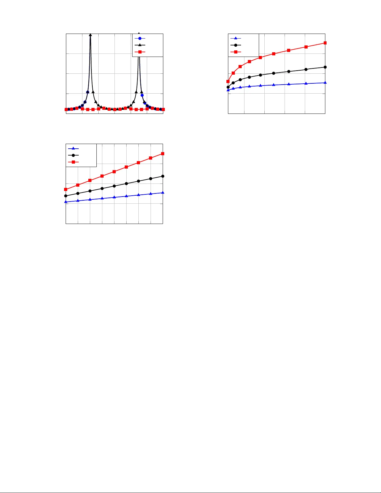
Enabling mmW a v e Communications with VCSEL-Based Light-Emitting Reconfigurable Intelligent Surfaces Rashid Iqbal * , Dimitrios Bozanis † , Dimitrios T yrov olas † , Christos K. Liaskos ‡ , Muhammad Ali Imran * , George K. Karagiannidis † , Hanaa Abumarshoud * * James W att School of Engineering, Uni versity of Glasgo w , Glasgow G12 8QQ, U.K. e-mail: r .iqbal.1@research.gla.ac.uk, { muhammad.imran, hanaa.abumarshoud } @glasgo w .ac.uk † Department of Electrical and Computer Engineering, Aristotle Uni versity of Thessaloniki, 54124 Thessaloniki, Greece e-mail: { dimimpoz, tyrov olas, geokarag } @auth.gr ‡ Uni versity of Ioannina and FOR TH, Greece e-mail: cliaskos@uoi.gr Abstract —This paper proposes a light-emitting reconfigurable intelligent surface (LeRIS) architectur e that integrates vertical cavity surface-emitting lasers (VCSELs) to jointly support user localization and mmW a ve communication. By le veraging the directional Gaussian beams and dual-mode diversity of VCSELs, we derive a closed-f orm method f or estimating user position and orientation using only three VCSEL sour ces. These esti- mates ar e then used to configure LeRIS panels f or directional mmW a ve beamforming, enabling optimized wave propagation in programmable wireless en vironments. Simulation results demon- strate that the pr oposed system achieves millimeter-le vel local- ization accuracy and maintains high spectral efficiency . These findings establish VCSEL-integrated LeRIS as a scalable and multifunctional solution f or future 6G programmable wir eless en vironments. Index T erms —Light-emitting RIS (LeRIS), Localization, VC- SEL, Optical wireless positioning I . I N T RO D U C T I O N The evolution tow ard sixth generation networks is fueled by div erse services and applications such as holographic telepres- ence, the metav erse, and industrial automation, which demand massiv e user access, high bandwidth efficienc y , and extremely low latency [1]. T o satisfy these requirements, future systems will increasingly rely on millimeter wav e (mmW av e) frequen- cies, yet operation in such bands faces critical challenges, including se vere path loss and susceptibility to blockages. T o address these obstacles, the concept of programmable wireless en vironments (PWEs) has been introduced, where reconfig- urable intelligent surfaces (RISs) reshape wav e propagation on demand and provide the precise manipulation of electro- magnetic signals required for reliable mmW av e operation. The effecti veness of this paradigm, howe ver , depends on accurate awareness of user positions, since inaccurate knowledge can lead to suboptimal RIS configuration and de graded service quality . This realization has motiv ated the de velopment of multi-functional RISs, which extend PWEs beyond communi- cation enhancement by incorporating localization capabilities [2]. Current research primarily explores this through enhanced electromagnetic capabilities using simultaneous reflection and refraction combined with advanced configuration schemes [2]. Howe ver , relying solely on electromagnetic configuration may introduce performance trade-offs, since optimizing the RIS for one task can compromise its ef fectiv eness for another . As a result, multi-functional RISs are expected to ev olve through lightweight architectural extensions, where comple- mentary elements enhance en vironmental a wareness without undermining their fundamental wav efront manipulation role. Among possible e xtensions, optical sources stand out as candidates since their predominantly line-of-sight behavior provides stable references for position and orientation through multiple inherent degrees of freedom, while their operation in a distinct spectral domain ensures isolation from the spectrum manipulated by RISs [3]. Se veral w orks hav e in vestigated light-emitting diode (LED) systems as optical anchors for localization, achieving centimeter-le vel positioning accuracy [4], [5]. Howe ver , their diffuse emission patterns constrain spatial resolution and preclude precise orientation estimation. Building on these observ ations, vertical ca vity surface-emitting lasers (VCSELs) hav e emer ged as compact alternati ves that combine precise beam control with fast modulation and low- power operation. Their highly directional Gaussian-profile beams provide increased angular resolution, while multiple op- tical modes of fer additional div ersity for enhanced localization. In this direction, the authors of [6] proposed a VCSEL array system with novel beam activ ation schemes that maintained connectivity under random user orientation while analyzing the tradeoff between div ergence and throughput, while the authors of [7] proposed VCSEL-based approaches using deep neural networks for joint position and orientation estimation with lower localization error compared to LED-based systems, and the authors of [8] in vestigated ultra-dense VCSEL array architectures supporting multi-gigabit transmission. The concept of light-emitting RISs (LeRIS) has been in- troduced, sho wing that embedding optical anchors within RIS panels can enhance localization accuracy and directly assist RIS configuration for impro ved spectral efficienc y [3]. Howe ver , current LeRIS designs have been limited to LED implementations, and to the best of the authors’ knowledge, no prior work has established closed-form localization and orientation estimation schemes that exploit the dual-mode spatial degrees of freedom of VCSELs for LeRIS. Motiv ated by the above, this paper introduces a VCSEL- based LeRIS-assisted PWE architecture that jointly supports localization, orientation estimation, and mmW av e communi- cation. Specifically , we introduce an architecture where three dual-mode VCSEL sources are inte grated along the perimeter of the panel to act as structured optical anchors. W e then deri ve closed-form expressions that exploit the Gaussian beam profile and dual-mode div ersity to ensure joint position and orienta- tion estimation. Through extensi ve simulations, we demon- strate that the proposed system achie ves millimeter -lev el lo- calization accuracy and robust orientation estimation while sustaining substantial spectral efficienc y gains for mmW av e communication, thereby establishing VCSEL-based LeRIS as a practical pathway for extending RIS capabilities tow ard multi-functional operation within PWEs. I I . S Y S T E M M O D E L W e consider a PWE in an indoor space, Fig. 1, where a mmW av e access point (AP) with a directional antenna is out- side the room and serves a single user equipment (UE) inside. The UE has a directional antenna and an optical recei ver . As mmW av e signals are susceptible to blockage in indoor spaces, a direct LoS link from the AP to the UE is often infeasible. T o address this, four LeRIS panels are mounted at the centers of the walls [9]. Each LeRIS integrates a programmable array of passiv e reflecting elements and VCSELs, enabling localization and joint control of electromagnetic reflection for dynamic routing based on UE awareness. T o localize the user , the UE estimates its position from optical signals emitted by VCSELs around the LeRIS perime- ters. The VCSELs produce narro w Gaussian beams that scan small angular ranges to cover azimuth sectors, which are more appropriate for localization services due to their directi vity , compared to the dif fusiv e nature of LEDs. Each VCSEL uses a distinct infrared frequency , allo wing the UE to separate the signals spectrally , infer its position, and report it to the AP ov er a control channel. The AP then configures the LeRIS panels to form directional mmW av e links to the UE. Fig. 1: Programmable W ireless en vironment with VCSEL-based LeRIS panels. A. VCSELs Channel Modeling T o support high-throughput communication under dynamic indoor conditions, the PWE lev erages the deployed LeRISs to form a mmW av e signal route to ward each selected UE, by utilizing the transmitted optical signals of the VCSELs to e xtract its location. Unlike con ventional dif fuse light emit- ters, such as LEDs, which exhibit broad angular dispersion and lower spatial coherence, VCSELs generate narro w , low- div ergence beams with Gaussian spatial intensity profiles that can be tightly controlled and directionally steered, thus being particularly suitable for precise localization. The optical channel between the i -th VCSEL and the UE is characterized by the intensity I i receiv ed at the user , assumed to follow a Gaussian distrib ution [7]: I i ( r 0 , d 0 ) = 2 P t,i π w 2 ( d 0 ) exp − 2 r 2 0 w 2 ( d 0 ) , (1) where P t,i is the transmitted optical power , r 0 is the radial distance from the beam center , and d 0 is the axial distance. The beam spot size w ( d 0 ) e volv es as w ( d 0 ) = w 0 s 1 + d 0 z R 2 , (2) where w 0 = λ o π θ div is the beam waist, θ div is the div ergence angle, λ o is the wav elength, and z R = π w 2 0 λ o is the Rayleigh range. The angular intensity at the UE becomes I i ( d i , ϕ i ) = 2 P t,i π w 2 ( d i cos ϕ i ) exp − 2 d 2 i sin 2 ϕ i w 2 ( d i cos ϕ i ) , (3) where d i is the distance and ϕ i the irradiance angle. The receiv ed LoS optical power at the UE’ s photodetector (PD) is then P LoS ,i = I i ( d i , ϕ i ) A PD cos ψ i rect ψ i Ψ , (4) with A PD denoting PD area, ψ i the incidence angle, and Ψ the half-angle field of view (FoV). The rect( · ) function enforces angular filtering based on the FoV . Howe ver , the total power measured at the PD includes noise, yielding P r,i = P LoS ,i + P n,i , (5) where P n,i = B o S i models the noise v ariance, with S i the one-sided po wer spectral density S i = A K + R PD P LoS ,i (2 q + RIN R PD P LoS ,i ) , (6) and B o the PD bandwidth. Here, A K = 4 k B T F n R L is the thermal noise term, where k B is Boltzmann’ s constant, T is temperature, R L is load resistance, and F n the preamplifier noise. The terms q , R PD , and RIN denote the electron charge, PD responsivity , and relative intensity noise, respectively [10]. Thus, the optical channel captures the physical beam propa- gation, recei ver orientation, and power con version effects. B. mmW ave Channel Modelling Based on the estimated user location and orientation, the AP selects a cascaded route L of participating LeRISs that connects the AP to the UE, where each LeRIS along this path is configured to steer the incident mmW av e signal to ward the next LeRIS, while the final LeRIS steers energy to ward the UE according to its estimated angular location ( ˆ θ r , ˆ ϕ r ) . For this purpose, each LeRIS panel, composed of M × N square reflecting elements with side length D , shapes the outgoing wa vefront based on the intended direction. Thus, the effecti ve gain of each LeRIS produced in the target direction ( θ , ϕ ) is giv en by G ( θ , ϕ ) = η eff 4 π | F ( θ , ϕ ) | 2 R 2 π 0 R π 2 0 | F ( θ , ϕ ) | 2 sin ( θ ) dθ dϕ , (7) where η eff denotes the aperture efficiency [11]. Moreover , F ( θ, ϕ ) is the far-field radiation pattern generated by the LeRIS array , which is given as [9] F ( θ , ϕ ) = M X m =1 N X n =1 e j ( k 0 ζ mn ( θ,ϕ )+ ω mn +Φ mn ) , (8) where k 0 = 2 π λ m is the wav enumber and λ m is the wav elength of the mmW a ve channel, and the term ζ mn ( θ , ϕ ) e xpresses the angular-dependent phase shift associated with the array’ s geometry and can be expressed as [9] ζ mn ( θ , ϕ ) = D sin( θ ) m − 1 2 cos( ϕ ) + n − 1 2 sin( ϕ ) +( x T − x R ) sin( θ ) cos( ϕ ) + ( y T − y R ) sin( θ ) sin( ϕ ) +( z T − z R ) cos( θ ) , (9) where ( x T , y T , z T ) are the coordinates of the transmitting or reflecting node, and ( x R , y R , z R ) denote the center of the receiving node. Additionally , the phase of fset ω mn , corre- sponding to the path delay from transmitter to the ( m, n ) -th reflecting element, is giv en by [9] ω mn = k 0 x T − D m − 1 2 sin( θ ) cos( ϕ ) − x R 2 + ( y T − y R ) 2 + z T − D m − 1 2 sin( θ ) sin( ϕ ) − z R 2 1 / 2 . (10) Finally , to steer energy accurately in the direction ( ˆ θ r , ˆ ϕ r ) , the phase shift Φ mn applied by each element is configured as [12] Φ mn = − k 0 D h m cos( ˆ ϕ r ) sin( ˆ θ r ) + n sin( ˆ ϕ r ) sin( ˆ θ r ) i − ω mn . (11) When steering to ward another LeRIS panel, the exact position and orientation of the tar get node are kno wn. Under such conditions, the beam is perfectly aligned with the desired direction, thus, the far -field response achie ves maximum con- structiv e interference, and the achiev able gain becomes G max = η eff M N . (12) Therefore, given that each LeRIS along the route, excluding the last, performs perfect beam steering toward a known position, the cumulati ve gain contributed by the first L − 1 LeRIS panels can be expressed as G cas = ( A eff G max ) L − 1 , (13) where A eff = M N λ 2 m 4 π , (14) denotes the effecti ve aperture of each LeRIS panel [12]. Ho w- ev er, for the last participating LeRIS in the route, the signal will be steered tow ard the estimated UE direction ( ˆ θ r , ˆ ϕ r ) , deriv ed from the proposed optical localization system. Specifi- cally , due to potential angular mismatch between the estimated and true UE direction ( θ u , ϕ u ) , the effecti ve beam alignment may degrade, resulting in a reduced directional gain [9]. As a result, the achiev able gain by the final LeRIS in the true UE direction is expressed as G L ( θ u , ϕ u ) = η eff · 4 π | F ( θ u , ϕ u ) | 2 R 2 π 0 R π 0 | F ( θ, ϕ ) | 2 sin ( θ ) dθ dϕ . (15) The UE is assumed to be equipped with a directional antenna featuring a constrained FoV , which limits the angular range ov er which the final LeRIS-to-UE link can be established. Specifically , a viable connection is possible only when the incoming beam direction lies within the o verlapping FoVs of both the LeRIS and the UE. The corresponding directional gain G r ( θ u ) for a beam with directi vity angle θ m is G r ( θ u ) = 2 π θ m , if | θ u | ≤ θ m , 0 , otherwise . (16) Consequently , the total directional gain accumulated along the entire route is expressed as G r = G cas · A eff · G L ( θ u , ϕ u ) · G r ( θ u ) , (17) where the final factor accounts for the UE’ s directional recep- tion. Assuming narro wband flat-fading mmW av e transmission, the baseband signal receiv ed by the UE is gi ven by y = p l p G t P t G r · x + w , (18) where x is the unit-energy transmitted symbol, G t is the AP antenna gain, P t is the transmit po wer , and w denotes the A WGN at the UE with v ariance σ 2 . Moreo ver , assuming a cascaded LeRIS network with L LeRISs, l p denotes the total path loss over the route, giv en by [13] l p = L +1 Y i =1 C 0 d r,i d r, 0 − n i , (19) where d r,i represents the distance of each segment, n i is the path loss exponent for the i -th segment, and C 0 = λ 2 m (4 π d r, 0 ) 2 is the free space path loss at the reference distance d r, 0 . T o this end, the achiev able spectral efficienc y at the user is then giv en by R = log 2 1 + l p G t γ t G r σ 2 , (20) where γ t = P t σ 2 , with (20) capturing the impact of beam steering accuracy , directional alignment, and environmental path loss on the end-to-end spectral efficiency . I I I . L O C A L I Z A T I O N T H R O U G H V C S E L BA S E D L E R I S T o determine the UE position within the PWE, receiv ed signal strength (RSS) measurements from VCSELs are used, since the distance-dependent attenuation of Gaussian beams carries geometric information for localization. Ho wev er , the highly directionality of VCSELs improv es spatial resolution but limits cov erage, so detection and placement depend on whether the PD lies within each narrow beam. Specifically , as it can be seen in (4), the PD receives power only within the beam footprint, making it essential to ensure that enough VCSELs are deployed for reliable estimation of both the UE’ s position and orientation. This requirement can be reduced by operating each VCSEL in more than one optical mode. In practice, VCSELs can support more than one transverse lasing mode, and different modes lead to Gaussian beams with differ - ent waist radii and Rayleigh ranges, providing distinct distance dependences without increasing the number of emitters. The following proposition states that multi-mode emission enables unique localization is achieved with three VCSELs under appropriate geometric and identifiability conditions. Pr oposition 1: The UE position r and orientation n can be uniquely determined from thr ee VCSELs if each emits sequentially in two distinguishable optical modes with known { P ( m ) t,i , w ( m ) 0 ,i , z ( m ) R,i } for m ∈ { a, b } , the VCSEL locations are non-collinear , and the unit vectors u i = s i − r ∥ s i − r ∥ , i = 1 , 2 , 3 , are linearly independent at the solution. Pr oof: Let the i -th VCSEL be at s i ∈ R 3 , and the UE at r ∈ R 3 , with unit normal n ∈ R 3 satisfying | n | = 1 . Owing to the high directionality of VCSELs, the irradiance can be considered aligned with the PD axis, i.e., ϕ = 0 ◦ , while only measurements fulfilling n · s i ≥ 0 are retained, corresponding to the FoV constraint of the PD. By assuming that the effect of noise is negligible, and setting each VC- SEL to emit sequentially in two optical modes, indexed by m ∈ { a, b } , with known parameters consisting of the transmit power P ( m ) t,i , the waist radius w ( m ) 0 , and the Rayleigh range z ( m ) R = π w ( m ) 0 2 /λ o , the recei ved power at the UE for each mode is P ( m ) i = β ( m ) i ( d i ) ( n · u i ) , (21) where β ( m ) i ( d ) = 2 A PD P ( m ) t,i π w 2 m ( d ) , and w ( m ) ( d ) = w ( m ) 0 r 1 + d/z ( m ) R 2 . Since both modes originate from the same VCSEL, the y share the same direction v ector u i , thus the factor ( n · u i ) in (21) is identical for m = a and m = b . T o eliminate this dependence on the unkno wn n , we can consider the ratio R i of the received powers, which is defined as R i = P ( a ) i P ( b ) i = β ( a ) i ( d i ) β ( b ) i ( d i ) = B a B b · 1 + d i /z ( b ) R 2 1 + d i /z ( a ) R 2 , (22) where B m = 2 A PD P ( m ) t,i π w ( m ) 0 2 . Thus, after some algebraic manipu- lations, the distance d i from the i -th VCSEL and the UE can be recov ered in closed form as d i = v u u u t 1 − ˜ R i ˜ R i z ( a ) R 2 − 1 z ( b ) R 2 , (23) where ˜ R i = R i B b B a . W ith three such ranges from non-collinear VCSELs, the UE position r is obtained by trilateration as the common intersection of ∥ r − s i ∥ 2 = d 2 i , i = 1 , 2 , 3 , (24) which reduces to a finite set. T o a void solving the full quadratic system, subtract the i = 1 equation from i = 2 , 3 to eliminate quadratic terms and obtain 2 ( s 2 − s 1 ) ⊤ ( s 3 − s 1 ) ⊤ r = " ∥ s 2 ∥ 2 − ∥ s 1 ∥ 2 − ( d 2 2 − d 2 1 ) ∥ s 3 ∥ 2 − ∥ s 1 ∥ 2 − ( d 2 3 − d 2 1 ) # , (25) which describes the line of intersection of the two planes. Intersecting this line with any sphere in (24) yields the unique feasible point inside the room. W ith ˆ r determined, we define ˆ u i = s i − ˆ r ∥ s i − ˆ r ∥ , c ( m ) i = P ( m ) i β ( m ) i ( d i ) . (26) Using a single mode (e.g., m = a ), the orientation follows from ˆ u ⊤ 1 ˆ u ⊤ 2 ˆ u ⊤ 3 | {z } U ∈ R 3 × 3 n = c ( a ) 1 c ( a ) 2 c ( a ) 3 | {z } c , (27) which establishes a direct relation between the orientation vector and the normalized measurements once the position has been fixed. Thus, considering that N V = 3 , the system (27) reduces to a 3 × 3 linear system, and, if det U = 0 , the orientation vector of the user can be written in closed form as ˜ n = U − 1 c , (28) which concludes the proof. Remark 1: Non-collinearity ensures a finite intersection in (24) and linear independence of { ˆ u i } ensures det U = 0 , enabling unique recovery of position and orientation. Remark 2: Compared to LED-based LeRIS [9], which typically needs at least four sources, three VCSELs suffice thanks to narrow beams and dual-mode operation. From Proposition 1, it follows that the UE position and orientation can be uniquely determined using three VCSELs when the effect of noise is considered negligible. Howe ver , in practice, the receiv ed optical signals at the PD are affected by noise, which perturbs the range estimates extracted from each VCSEL. Since these ranges form the basis of the localization procedure, it is essential to quantify the error incurred from each single VCSEL–UE link. In this direction, the following proposition provides the estimation error for the i -th VCSEL to the UE link. Pr oposition 2: The estimation error for the i -th VCSEL to the UE link is giv en as ∆ d i = d i 1 − 1 √ 1 + α i s α i − z 2 R,i d 2 i , (29) where α i = P LoS ,i P n,i . Pr oof: The localization error is defined as the dif ference between the actual and estimated distance, i.e., ∆ d i = d i − ˆ d i . (30) Considering that ϕ = 0 ◦ due to the high directivity of VCSELs, and that the beam lies within the UE’ s FoV , the true distance d i can be written through (4) as d i = s z 2 R,i 2 P t,i A PD cos ψ i π w 2 0 ,i P LoS ,i − 1 . (31) Furthermore, considering that P r,i = P LoS ,i 1 + 1 α i , by replacing P LoS ,i with P r,i in (31), we can obtain the estimated distance ˆ d i as ˆ d i = s α i d 2 i − z 2 R,i α i + 1 . (32) Substituting (31) and (32) into (30) giv es (29), which con- cludes the proof. A. LeRIS-based Communication After the UE position has been determined and the LeRIS–UE and LeRIS–LeRIS link visibility has been iden- tified according to FoV and geometric reachability , the AP selects a feasible cascaded route toward the UE. Multiple candidate routes are ev aluated, with feasibility captured by χ π = Y s ∈ S ( π ) χ s , (33) where S ( π ) is the set of segments of route π , and χ s ∈ { 0 , 1 } indicates whether segment s satisfies the FoV and steering constraints. Specifically , χ s is a binary indicator that equals 1 only when the segment alignment falls within the PD’ s FoV as constrained in (4), and simultaneously satisfies the angular directivity requirement for viable steering defined in (16). As established in (19), the received signal ov er a cascaded LeRIS route is shaped jointly by the multiplicativ e channel gains of its segments and the corresponding path losses, thus the optimal route maximizes the spectral efficienc y in (20). So, the end- to-end spectral efficiency for the UE can be expressed as R = max π R π , (34) with R π = χ π log 2 1 + G t l p ( π ) G r ( π ) σ 2 . (35) Here, l p ( π ) denotes the cumulative path loss along the seg- ments of π , and G r ( π ) is the cascaded beamforming gain from the participating LeRIS panels configured hop by hop tow ard the next LeRIS and the recei ve gain of the directional UE antenna within the UE F oV . The steering angles for each LeRIS hop and for the final LeRIS–UE segment follow from the estimated UE position as in [9], completing the end-to-end configuration for the selected route. I V . S I M U L A T I O N R E S U LT S In this section, we e valuate the performance of an indoor system with a single UE and four LeRIS panels, whose corresponding parameter v alues for the VCSELs are listed in T able I, while the communication parameters are provided in T able II. Each LeRIS is equipped with 24 VCSELs placed along its perimeter , arranged so that their beams jointly span an azimuthal sector of 120 ◦ with an ele vation span of 60 ◦ , while each VCSEL rotates to cov er a 5 ◦ azimuthal segment and thereby provide both wide angular cov erage and fine resolution. As a result, the deployed beams complement one another to span the served area, enabling user localization and supporting LeRIS-based communication. Moreov er , the UE coordinates are uniformly sampled relati ve to the corner origin within x u ∈ [0 , 10] m, y u ∈ [0 , 10] m, and z u = 1 . 5 m, corresponding to a typical indoor user height aligned with the LeRIS plane. The azimuth orientation angle ϕ UE of the user is uniformly distributed o ver [0 , 2 π ] , while the elev ation orientation is fixed at θ UE = 0 , reflecting alignment with the LeRISs’ centres. Finally , to quantify the system performance under realistic conditions, we conduct a Monte Carlo simu- lation with 10 5 iterations, where in each iteration, both the user position and orientation are randomly generated within the specified bounds. T ABLE I: S I M U L A T I O N P A RA M E T E R S F O R V C S EL S Parameter V alue LeRIS 1 Centre coordinates (0 , 5 , 1 . 5) LeRIS 2 Centre coordinates (10 , 5 , 1 . 5) LeRIS 3 Centre coordinates (5 , 0 , 1 . 5) LeRIS 4 Centre coordinates (5 , 10 , 1 . 5) PD area A PD = 1 cm 2 T ransmit po wer P t,i = 10 mW Beam waist ω 0 = 5 . 6 µ m Speed of light c = 3 × 10 8 m / s VCSEL wavelength λ o = 950 nm Optical bandwidth B o = 1 GHz Relativ e intensity noise RIN = − 155 dB/HZ Preamplifier noise figure F n = 5 dB PD FoV Ψ = 90 ◦ Noise variance P n,i = 2 . 5 × 10 − 12 A 2 Load resistance R L = 50Ω Absolute temperature T = 300K Boltzmann constant k B = 1 . 380649 × 10 − 23 K / J PD responsivity R PD = 0 . 7 A/W T ABLE II: S I M U L A T I O N P A RA M E T E R S F O R M M W A V E Parameter V alue mm-wav e W avelength λ m = 10 − 2 m T ransmit po wer P t = 1 W T ransmitter gain G t = 10 dB Angle of directivity θ r = π 3 Reference distance d r, 0 = 1 m Path loss exponent n i = 2 Element spacing D = λ m 2 RIS efficiency n eff = 100% A WGN variance σ 2 = − 130 dB Fig. 2 shows the localization error ∆ d i versus the azimuth angle for different numbers of acti ve panels. W ith a single panel at 0 ◦ , the error remains low within its 60 ◦ footprint but increases sharply outside this range, reflecting the high precision but limited coverage of directional VCSEL beams. Activ ating two opposite LeRIS panels extends coverage and lowers error ov er a wider range, while full acti vation of all four panels maintains consistently low error across the full 360 ◦ orientation range. This demonstrates that cooperati ve VCSEL-based LeRIS panels can ensure robust and accurate localization regardless of user orientation. Compared to wide- beam LED systems, the use of narrow-beam VCSELs with rotational scanning provides significantly higher accuracy , validating the ef ficiency of the proposed architecture. Fig. 3 presents the spectral ef ficiency R as a function of SNR for L = 1 , L = 2 , and L = 4 LeRIS panels, each with N = 2500 elements. As e xpected, increasing the number of activ e panels enhances spectral ef ficiency by offering more reflectiv e paths and improving localization precision. This enables reliable high-rate communication across a broad SNR range, especially at higher SNRs where reflected beams are more ef fectiv ely exploited. Fig. 4 illustrates the spectral efficiency R as a function of the number of reflecting elements N per LeRIS panel for three deployment configurations. When only a single panel is active, the system exhibits restricted angular cov erage, which limits the likelihood of ef fecti ve beam alignment and reduces the spatial div ersity av ailable for both localization and communication. This limitation leads to degraded spectral 0 ◦ 60 ◦ 120 ◦ 180 ◦ 240 ◦ 300 ◦ 360 ◦ 0 0 . 5 1 1 . 5 2 ϕ UE ∆ d i,k (mm) L = 1 L = 2 L = 4 Fig. 2: ∆ d versus azimuth angle for different values of L . 90 95 100 105 110 115 120 125 130 0 4 8 12 16 SNR(dB) R (bps/Hz) L = 1 L = 2 L = 4 Fig. 3: R versus SNR for various numbers of LeRIS panels. efficienc y , particularly in scenarios requiring omnidirectional cov erage or high-reliability links. As additional LeRIS panels are acti vated, the PWE gains greater spatial flexibility , allo w- ing it to capture stronger reflection paths and provide broader angular support for the user . The resulting improv ements in beamforming gain and localization precision translate into a marked increase in spectral ef ficiency . Notably , the L = 4 configuration consistently outperforms the L = 1 case across all v alues of N , achieving more than twice the throughput in sev eral regimes. These results underscore the critical role of both panel multiplicity and element scalability in enhancing the ov erall performance of VCSEL-based LeRIS systems. V . C O N C L U S I O N This paper presented a VCSEL-based LeRIS architecture for PWEs that enables joint user localization, orientation estimation, and mmW av e communication. By exploiting the Gaussian beam profile and dual-mode div ersity of VCSELs, closed-form solutions were deri ved to estimate user position and orientation using only three VCSEL sources integrated along the panel perimeter . A distance estimation error expres- sion was deri ved to e valuate localization accuracy . Finally , simulation results confirmed that the proposed system achie ves millimeter-le vel localization accuracy and robust orientation estimation while maintaining high spectral efficienc y . These findings demonstrate that VCSEL-integrated LeRIS panels offer a practical and scalable solution for enabling multi- functional RIS operation in future 6G wireless networks. 100 500 1 , 000 1 , 500 2 , 000 2 , 500 0 4 8 12 16 N R (bps/Hz) L = 1 L = 2 L = 4 Fig. 4: R versus N for various numbers of LeRIS panels R E F E R E N C E S [1] Z. Zhang, Y . Xiao, Z. Ma, M. Xiao, Z. Ding, X. Lei, G. K. Karagiannidis, and P . Fan, “6G Wireless Networks: V ision, Requirements, Architecture, and Key T echnologies, ” IEEE Commun. Surv . T ut. , vol. 23, no. 1, pp. 70–120, 2021. [2] A. Tishchenko, M. Khalily , A. Shojaeifard, F . Burton, E. Bj ¨ ornson, M. Di Renzo, and R. T afazolli, “The Emergence of Multi-Functional and Hybrid Reconfigurable Intelligent Surfaces for Integrated Sensing and Communications – A Survey , ” IEEE Commun. Surv . T utor . , pp. 1–1, 2025. [3] D. T yrovolas, D. Bozanis, S. A. T egos, V . K. Papanik olaou, P . D. Diamantoulakis, C. K. Liaskos, R. Schober, and G. K. Karagianni- dis, “Empowering Programmable W ireless En vironments With Optical Anchor-Based Positioning, ” IEEE Netw . , vol. 39, no. 1, pp. 14–20, 2025. [4] D. Bozanis, N. G. Evgenidis, V . K. Papanikolaou, P . S. Bouzinis, S. A. T egos, A. A. Dowhuszko, P . D. Diamantoulakis, and G. K. Karagiannidis, “Indoor 3D V isible Light Positioning Analysis with Channel Estimation Errors, ” Proc. 30th Int. Conf. Systems, Signals and Image Pr ocess. (IWSSIP) , pp. 1–4, 2023. [5] D. Bozanis, D. T yrovolas, V . K. Papanikolaou, S. A. T egos, P . D. Diamantoulakis, C. K. Liaskos, R. Schober , and G. K. Karagiannidis, “Closed-Form Location and Orientation Estimation in Optical Wireless Systems, ” Proc. IEEE W ireless Commun. Netw . Conf. (WCNC) , pp. 1–6, 2025. [6] Z. Zeng, M. D. Soltani, M. Safari, and H. Haas, “A VCSEL Array T ransmission System W ith Novel Beam Activ ation Mechanisms, ” IEEE T rans. Commun. , vol. 70, no. 3, pp. 1886–1900, 2021. [7] R. Ahmad, H. Kazemi, E. Sarbazi, and H. Haas, “Joint Position and Orientation Estimation in VCSEL-Based LiFi Networks: A Deep Learn- ing Approach, ” Pr oc. IEEE Global Commun. Conf. (GLOBECOM) , pp. 3676–3681, 2023. [8] E. Sarbazi, H. Kazemi, M. Dehghani Soltani, M. Safari, and H. Haas, “A Tb/s Indoor Optical Wireless Access System Using VCSEL Arrays, ” Pr oc. IEEE Int. Symp. P ers., Indoor and Mobile Radio Commun. (PIMRC) , pp. 1–6, 2020. [9] D. Bozanis, D. T yrovolas, V . K. Papanikolaou, S. A. T egos, P . D. Diamantoulakis, C. K. Liaskos, R. Schober , and G. K. Karagiannidis, “Location-Driv en Programmable W ireless En vironments through Light- emitting RIS (LeRIS), ” arXiv preprint , 2024. [10] H. Kazemi, E. Sarbazi, M. Crisp, T . E. H. El-Gorashi, J. M. H. Elmirghani, R. V . Penty , I. H. White, M. Safari, and H. Haas, “A Novel T erabit Grid-of-Beam Optical Wireless Multi-User Access Network with Beam Clustering, ” IEEE T rans. Commun. , pp. 1–1, 2025. [11] T . J. Cui, M. Qi, X. W an, J. Zhao, and Q. Cheng, “Coding Metamaterials, Digital Metamaterials and Programmable Metamaterials, ” Light: Sci. Appl. , vol. 3, p. e218, 2014. [12] H. T aghvaee, A. Cabellos-Aparicio, J. Georgiou, and S. Abadal, “Error Analysis of Programmable Metasurfaces for Beam Steering, ” IEEE J. Emer g. Sel. T op. Cir cuits Syst. , vol. 10, no. 1, pp. 62–74, 2020. [13] D. T yrovolas, S. A. T egos, E. C. Dimitriadou-Panidou, P . D. Dia- mantoulakis, C. K. Liaskos, and G. K. Karagiannidis, “Performance Analysis of Cascaded Reconfigurable Intelligent Surface Networks, ” IEEE Wir eless Commun. Lett. , vol. 11, no. 9, pp. 1855–1859, 2022.
Original Paper
Loading high-quality paper...
Comments & Academic Discussion
Loading comments...
Leave a Comment