Rotatable Antenna Assisted Mobile Edge Computing
This paper investigates a rotatable antenna (RA) assisted mobile edge computing (MEC) network, where multiple users offload their computation tasks to an edge server equipped with an RA array under a time-division multiple access protocol. To maximiz…
Authors: Ji Wang, Hao Chen, Yixuan Li
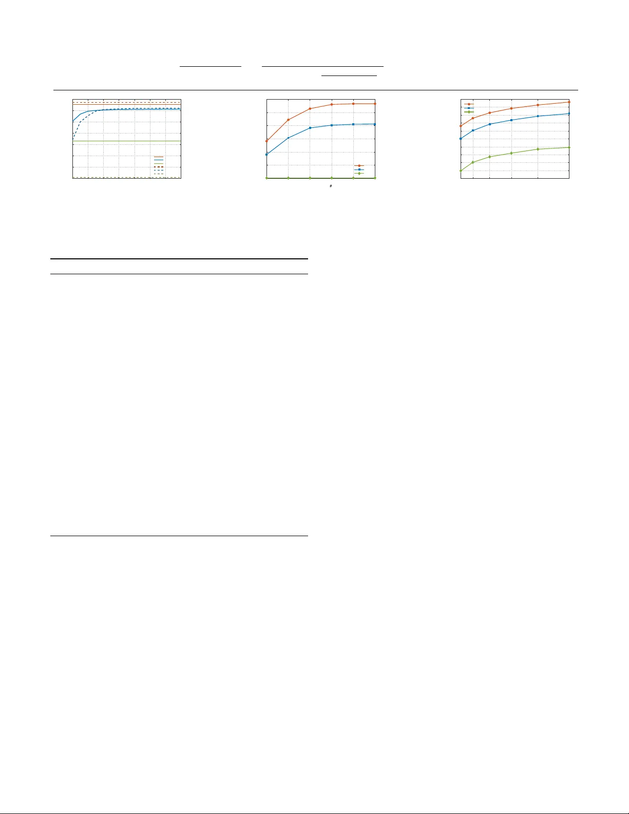
1 Rotatable An tenna Assisted Mobile Edge Computing Ji W ang, Senior Mem b er, IEEE, Hao Chen, Yixuan Li, Jun Zhang, Xingw ang Li, Senior Mem b er, IEEE, Ming Zeng, and Octa via A. Dobre, F ello w, IEEE Abstract—This pap er inv estigates a rotatable antenna (RA) assisted mobile edge computing (MEC) netw ork, where multi- ple users ooad their computation tasks to an edge server equipp ed with an RA array under a time-division multiple access protocol. T o maximize the weigh ted sum computation rate, w e formulate a join t optimization problem ov er the RA rotation angles, time-slot allo cation, transmit pow er, and lo cal CPU frequencies. Due to the non-conv ex nature of the form ulated problem, a scenario-adaptive h ybrid optimization algorithm is prop osed. Sp ecically , for the dynamic rotating scenario, where RAs can exibly reorient within each time slot, we derive closed-form optimal antenna p ointing v ectors to enable a lo w-complexity sequen tial solution. In con trast, for the static rotating scenario where RAs maintain a unied orienta- tion, we develop an alternating optimization framew ork, where the non-con vex RA rotation constraints are handled using successiv e con v ex appro ximation iterativ ely with the resource allo cation. Sim ulation results demonstrate that the proposed RA assisted MEC netw ork signicantly outperforms conv en- tional xed-antenna MEC netw orks. Owing to the additional spatial degrees of freedom in tro duced b y mec hanical rotation, the exibility of RAs eectively mitigates the severe b eam misalignmen t inherent in xed-antenna systems, particularly under high an tenna directivit y . Index T erms—Rotatable antennas, mobile edge computing, task ooading, antenna p ointing, alternating optimization. I. Introduction T HE rapid proliferation of In ternet-of-Things (IoT) devices and articial intelligence–driv en applications is imp osing unpreceden ted computational and latency requiremen ts on sixth-generation wireless netw orks. The paradigm of mobile edge computing (MEC) has emerged as a piv otal arc hitecture to mitigate these bottlenecks, primarily via the migration of computationally demanding w orkloads from capacity-limited terminals to proximal edge infrastructure [1]. Nev ertheless, the p erformance Ji W ang, Hao Chen, and Yixuan Li are with the De- partment of Electronics and Information Engineering, College of Ph ysical Science and T echnology , Cen tral China Normal Universit y , W uhan 430079, China (e-mail: jiwang@ccn u.edu.cn; 1280904251ch@mails.ccn u.edu.cn; yixuanli@mails.ccnu.edu.cn). Jun Zhang is with the School of Physics and Electronic Engi- neering, Hub ei Universit y of Arts and Science, Xiangyang 441053, China, and also with the Hub ei Provincial Engineering Research Center of Emergency Comm unication T echnology and System, Xi- angyang 441053, China (e-mail: hbuas_zhangjun@hbuas.edu.cn). (Corresponding author: Jun Zhang.) Xingwang Li is with the School of Physics and Electronic Infor- mation Engineering, Henan Polytec hnic Universit y , Jiaozuo 454003, China (e-mail: lixingwang@hpu.edu.cn). Ming Zeng is with the Departmen t of Electrical and Computer Engineering, Lav al Universit y , Queb ec City , QC G1V 0A6, Canada (e-mail: ming.zeng@gel.ulav al.ca). Octavia A. Dobre is with the F aculty of Engineering and Applied Science, Memorial Universit y , St. John’s, NL A1C 5S7, Canada (e- mail: o dobre@mun.ca). Fig. 1. The prop osed RA assisted MEC system mo del. gains achiev able b y MEC are fundamentally limited by the quality of the wireless computation ooading links, making communication eciency a critical b ottlenec k [2]. Most existing MEC systems rely on xed antennas (F As) at the base station. While directional antennas are desirable for their high gain, extended transmission range, and strong interference resistance, their inherent narro w b eamwidths make them highly sensitiv e to direc- tionalit y . Once a user’s p osition deviates from the xed p oin ting direction, the adv antage of high gain instantly b ecomes a disadv antage, leading to a sharp decline in link qualit y . This physical rigidity often results in sev ere b eam misalignment and degraded ooading eciency , particularly in scenarios with uneven user distributions or dynamically changing channel conditions [3]. Although con v entional multiple-input multiple-output architectures partially exploit spatial diversit y , the xed placement and orien tation of antenna elemen ts inherently constrain their abilit y to fully capitalize on spatial c hannel v ariations in data-in tensiv e MEC applications. T o address these limitations, recongurable intelligen t surfaces (RISs) [4]–[7] and pinching an tennas (P As) [8], [9] explore spatial degrees of freedom, but they face c hallenges suc h as double-fading eects and hardware implementa- tion complexity , resp ectively . In contrast to RIS- and P A-based approac hes that manipulate the propagation medium or radiation lo cation, rotatable antennas (RAs) exploit spatial adaptability by mec hanically steering the an tenna b oresight in three-dimensional (3D) space to align with dominant c hannel directions [10]. By leveraging mec hanical degrees of freedom to trade for spatial degrees of freedom, RAs provide more precise and stronger b eam alignmen t. This mec hanism eectiv ely mitigates the severe b eam misalignment inheren t in xed-antenna systems, ensuring that the high gain of directional antennas is fully utilized ev en for disp ersed users. Moreo ver, compared with mo v able antennas, which require contin uous p osi- 2 tional adjustments and inc ur signicant mechanical and con trol complexity [11], RAs oer a substantially low er- complexit y solution by leveraging rotational motion only , making them particularly attractive for practical MEC deplo ymen ts. Recen t studies hav e established a growing b o dy of work on RA-assisted wireless systems, encompassing channel mo deling [10], ecient channel estimation strategies [12], and adv anced applications suc h as integrated sensing and communications [13], physical-la y er security [14], and h ybrid mov able–rotatable antenna architectures [15]. No- tably , these works ha v e theoretically and exp erimentally v eried that RA-assisted systems outp erform con ven tional xed-an tenna systems in v arious scenarios [10], [12]–[14]. It has b een demonstrated that the p erformance gain of RAs increases with the antenna directivity factor, conrming that rotational exibilit y is essen tial to un- lo c k the p oten tial of narro w-b eam directional an tennas. F urthermore, the feasibility of RA implemen tation has b een v alidated through hardware prototypes and dynamic demonstrations [10]. How ever, the integration of RAs into MEC frameworks has received scant attention in the existing literature. In particular, existing MEC-orien ted resource allo cation framew orks do not account for the rotational degrees of freedom oered by RAs, nor do they in v estigate the synergistic orchestration of antenna orien- tation alongside transmission and pro cessing resources to impro v e ooading eciency . T o fully unlo ck the p otential of RAs in MEC, we form ulate a joint resource optimization problem that maximizes the weigh ted sum computation rate by jointly optimizing the RA rotation angles, time-slot durations, transmit p ow er allo cation, and lo cal CPU frequencies. T o address the non-conv ex problem, we develop a scenario- adaptiv e hybrid optimization algorithm (SAHO). This strategy eciently adapts the solution structure to the RA op erating mo de to balance p erformance and complex- it y . Specically , for the dynamic rotating scenario, w e exploit the derived closed-form optimal pointing solution to decouple the problem, allowing for a fast sequential optimization of antenna orientation and ooading re- sources. Conv ersely , for the practical static rotating sce- nario, where v ariables are intricately coupled, we prop ose an alternating optimization (AO) metho d. This metho d iterativ ely up dates the RA rotation angles via successiv e con v ex approximation (SCA) and the ooading resources via conv ex optimization until conv ergence. I I. System Mo del Fig. 1 depicts the considered uplink MEC framework, wherein a base station (BS) in tegrated with an edge serv er supp orts M users, each ha ving a single antenna. The BS utilizes a uniform planar array (UP A) comp osed of K = K x × K y RAs, with K x and K y represen ting the arra y dimensions along the x- and y-axes. T ransmission is go v erned b y a time-division multiple access (TDMA) proto col with a frame length of T . A. Netw ork Geometry and Channel Model The UP A is deploy ed in the x-y plane, with ad- jacen t elemen ts separated b y a distance ∆ . The co ordinate of the k -th RA is given b y w k = [ k x ∆ , k y ∆ , 0] T , where k x and k y are indices relativ e to the arra y cen ter. The m -th user is lo cated at u m = [ r m sin ψ m cos φ m , r m sin ψ m sin φ m , r m cos ψ m ] T , where r m denotes the distance of user m from the origin, and ψ m ∈ [0 , π ] and φ m ∈ − π 2 , π 2 represen t the zenith and azimuth angles of the m -th user relative to the co ordinate origin, resp ectively . Unlik e xed antenna systems, each RA k can mec hani- cally rotate its b oresight direction, c haracterized by a unit p oin ting vector f k ∈ R 3 . Let θ z ,k and ϕ a,k represen t the zenith and azim uth denitions for the rotation of the k - th RA. Accordingly , its p ointing v ector is formulated as f k = [sin θ z ,k cos ϕ a,k , sin θ z ,k sin ϕ a,k , cos θ z ,k ] T . T o av oid hardw are coupling, the rotation is constrained by a max- im um zenith angle θ max , i.e., 0 ≤ θ z ,k ≤ θ max . Here, ( ϵ, ϕ ) denotes the incident angle tuple c haracterizing an arbitrary spatial direction relativ e to the RA’s boresight axis. Due to the symmetry of the antenna pattern, the gain dep ends only on ϵ . A ccordingly , the eective antenna gain from user m to RA k follows G k,m = G 0 cos 2 p ( ϵ k,m ) , where G 0 is the maximum gain, p is the directivity factor, and cos( ϵ k,m ) ≜ f T k q k,m represen ts the cosine of the misalignmen t angle, with q k,m ≜ u m − w k ∥ u m − w k ∥ . Assuming quasi-static at fading, the ov erall m ultipath c hannel betw een user m and the k -th RA at the BS is mo deled as h k,m ( f k ) = L ( d k,m ) G k,m g k,m . Here, L ( d k,m ) characterizes the large-scale attenuation, whic h is formulated as L ( d k,m ) = A 0 ( d 0 /d k,m ) α m . In this ex- pression, d k,m represen ts the spatial separation b et w een user m and the k -th RA, while A 0 and α m denote the c hannel gain at the reference distance d 0 = 1 m and the path-loss exp onent, resp ectively . The small-scale fading coecient g k,m is mo deled as a sup erp osition of a deterministic line-of-sight (LoS) path and a scattered comp onent, go verned b y the Rician factor κ m . This is formulated as g k,m = κ m / ( κ m + 1) ¯ g k,m + 1 / ( κ m + 1) ˜ g k,m , wherein g k,m = e − j 2 πd k,m λ signies the LoS phase rotation, and ˜ g k,m ∼ C N (0 , 1) captures the non- LoS Ra yleigh fading eects. W e dene the p oin ting matrix collecting all RA boresight vectors as F ≜ [ f 1 , f 2 , . . . , f K ] . Then, the channel vector from user m to the BS is written as h m ( F ) ≜ [ h 1 ,m ( f 1 ) , h 2 ,m ( f 2 ) , . . . , h K,m ( f K )] T .F or ana- lytical con venience, we assume that the BS has acquired the global channel state information of all links. B. Computation and Ooading Mo dels W e adopt a partial ooading mo del where tasks are executed lo cally or ooaded to the RA assisted edge server via TDMA. 1) Lo cal Computing: F or user m , let f m b e the CPU frequency . W e dene the lo cal CPU frequency v ector for all users as f ≜ [ f 1 , f 2 , . . . , f M ] T . The lo cally processed data size is R loc ,m = T f m /C , and the energy consumption is E loc ,m = T r c f 3 m , with T and r c represen ting the duration 3 of the en tire time frame and the eective capacitance parameter, resp ectively . 2) Computation Ooading: Under the TDMA sc heme, users transmit in orthogonal slots τ m , eliminating inter- user interference. Considering a comm unication o verhead factor v m > 1 , which accoun ts for channel co ding redun- dancy and protocol headers, the ooaded data size R of f ,m is given by R o ,m = τ m B v m log 2 ( 1 + p m ∥ h m ( F ) ∥ 2 σ 2 ) , (1) where B is the bandwidth, p m is the transmit pow er, and σ 2 is the noise pow er. The corresp onding energy consumption E o ,m is denoted as E o ,m = τ m ( p m + p c,m ) , where p c,m is the circuit p ow er consumption. C. Problem F orm ulation W e establish the computation rate maximization mo del (P1) b y join tly optimizing the RA p ointing matrix F , lo cal CPU frequency vector f , time-slot allocation v ector τ , and transmit p o w er v ector p . Specically , F determines the antenna p ointing directions of the RAs sub ject to the ph ysical rotation constraints, while f , τ , and p co ordinate the computation and communication resources under en- ergy and latency budgets. The problem is formulated as (P1) : max p , τ , f , F M m =1 R loc ,m + R o ,m (2a) s.t. E o ,m + E loc ,m ≤ E max , ∀ m, (2b) M m =1 τ m ≤ T , 0 ≤ τ m ≤ T , ∀ m, (2c) p m ≥ 0 , f m ≥ 0 , ∀ m, (2d) R loc ,m + R o ,m ≥ R min , ∀ m, (2e) 0 ≤ θ z ,m ≤ θ max , ∀ m. (2f ) I I I. Joint Optimization Solution and Algorithm The non-conv exity inherent in (P1) arises principally from the complex in terplay in volving the RA p ointing matrix F , the resource allocation v ariables ( { f , p , τ } ), and the non-conv ex unit-mo dulus constrain ts on the p ointing v ectors. Considering the diculty of directly solving the problem P1, w e decouple the problem in to RA rotation optimization and ooading optimization subproblems. F or RA rotation optimization, w e separately address the dynamic and static rotatable antenna scenarios, account- ing for the rotation speed of RAs relativ e to the TDMA frame length. In the ooading optimization stage, the p oin ting matrix is held xed, and the remaining resource allo cation problem b ecomes conv ex, allowing it to b e solv ed eciently . A. RA Rotation Optimization In the RA rotation optimization pro cedure, we focus on optimizing the RA p ointing matrix F to maximize the directional gain, while k eeping the ooading parameters { f , p , τ } xed. W e consider tw o scenarios based on the RA’s rotation timescale: 1) dynamic rotation, and 2) static rotation. 1) Dynamic rotation: Under the uplink rate within the time slot, the optimization of antenna orientation aims to maximize pro jection b et w een f k and q k,m , whic h can b e form ulated as (P2) : max f k f T k q k,m (3a) s.t. ∥ f k ∥ = 1 , (3b) 0 ≤ arccos( f T k e 3 ) ≤ θ max , (3c) where, e 3 = [0 , 0 , 1] T corresp onds to the standard basis v ector aligned with the z-axis. The ob jectiv e f T k q k,m = cos( ϵ k,m ) represen ts the directional projection b etw een the RA b oresight and the user direction. Maximizing this v alue is equiv alent to minimizing the p ointing deviation ϵ k,m . The (P2) is a constrained linear optimization ov er a unit sphere and admits a closed-form global optim um whic h is given by f ⋆ n = q k,m , if arccos( u T m,n e 3 ) ≤ θ max , sin θ max cos ϕ a,k sin θ max sin ϕ a,k cos θ max , otherwise , (4) where the rotation angles are calculated as θ z ,k ≜ min arccos q T k,m e 3 , θ max , (5) ϕ a,k ≜ arctan2 q T k,m e 2 , q T k,m e 1 , (6) and the standard basis vectors are dened as e 1 = [1 , 0 , 0] T , e 2 = [0 , 1 , 0] T , and e 3 = [0 , 0 , 1] T . When the user direction lies within the rotation range (i.e., arccos( q T k,m e 3 ) ≤ θ max ), the RA b oresigh t is steered to coincide exactly with the user’s angular direction, thereb y attaining the peak directional gain. Otherwise, the RA is rotated to its maximum zenith angle θ max while maintaining the azimuth alignmen t, ac hieving “edge alignmen t” within the feasible region. Consequen tly , the optimal pointing matrix for all RAs in time slot m is F ⋆ = [ f ⋆ 1 , f ⋆ 2 , . . . , f ⋆ K ] . This result aligns with theoretical predictions, as the BS realizes the p eak directional gain K G 0 pro vided that the b oresigh t axis of ev ery RA is strictly steered to ward the user’s angle of arriv al, i.e., f k = q k,m . 2) Static rotation: How ever, the assumption of exible re-orien tation within eac h time slot is ideal but practi- cally challenging. Due to the inheren t mechanical inertia, the rotation sp eed of RAs is signican tly slo w er than the time-slot switc hing frequency in TDMA proto cols. Consequen tly , it is ph ysically impossible for RAs to instan taneously realign their b oresight for dieren t users in consecutive slots. Instead, a unied antenna orientation m ust b e determined to serve all users eectively through- out the entire timeframe. F or a given ooading parameter { f , p , τ } , problem (P1) can b e reform ulated as (P3) max F M m =1 ( R loc ,m + R o ,m ) (7a) s.t. 0 ≤ θ z ,k ≤ θ max , ∀ k . (7b) 4 Crucially , the deection angles primarily mo dulate the c hannel p o w er gain via the pro jection term cos( ϵ k,m ) . T o facilitate the SCA-based algorithm, we rewrite the channel co ecien t b y grouping the constan t terms and explicitly expressing the dep endence on the p ointing vector f k . The c hannel is reformulated as h m ( f k ) = ˜ β m,k f T k q k,m p , (8) where ˜ β m,k ≜ L ( d m,k ) G 0 g k,m . By substituting the reform ulated scalar c hannel ele- men ts from (8) in to the system c hannel v ector h m ( F ) , it b ecomes evident that the eective channel gain is directly determined b y the RA p ointing matrix F . Consequently , the optimization in (P3) is equiv alent to maximizing the ooading sum rate with resp ect to F . (P4) max F M m =1 τ m B v m log 2 1 + p m ∥ h m ( F ) ∥ 2 τ m σ 2 (9a) s.t. cos( θ max ) ≤ f T k e 3 ≤ 1 , ∀ k, (9b) ∥ f k ∥ = 1 , ∀ k . (9c) Here, (9b) mirrors the constraint in (7b), while (9c) strictly enforces the unit-norm requirement on f k . Since Problem (9) retains its non-conv ex character, rendering a direct solution in tractable, we resort to the SCA frame- w ork to construct a con vex surrogate, thereb y iterativ ely approac hing a lo cal optimum. Sp ecically , during the ( i + 1) -th up date, given the prior estimates F ( i ) and R ( i ) of f , w e linearize the logarithmic term in (9) via a rst-order T aylor expansion around f ( i ) k , yielding the approximation Λ ( i +1) r ( F ) formulated b elow ˜ h m,k = ∂ h m,k ( f ( i ) k ) ∂ f ( i ) k = ˜ β m,k p ( f ( i ) k ) T q k,m p − 1 q k,m . (10) Consequen tly , for the ( i + 1) -th iteration, problem (P4) is reform ulated via approximation as (P5) max F Λ ( i +1) r ( F ) (11a) s.t. (9b) , (9c) . (11b) Nev ertheless, (P5) retains its non-conv ex character arising from the unit-mo dulus restriction in (9c). Con- sequen tly , w e apply a relaxation to ∥ f k ∥ ≤ 1 , thereby establishing the conv ex formulation presented b elow (P6) max F Λ ( i +1) r ( F ) (13a) s.t. cos( θ max ) ≤ f T k e 3 ≤ 1 , ∀ k, (13b) ∥ f k ∥ ≤ 1 , ∀ k . (13c) Since (P6) constitutes a standard conv ex optimization form ulation, it admits ecient n umerical solutions using the CVX to olkit. F urthermore, o wing to the relaxation applied to the equalit y restriction (13c), the resulting optimal v alue of (P6) serves as a theoretical upp er b ound for the original problem (P5). After obtaining the optimal solutions of the CPU frequencies, w e normalize each p oint- ing vector f k in F to satisfy constraint (9c), i.e., f ∗ k = f k ∥ f k ∥ . This normalization only scales f k to a unit vector without c hanging its direction; hence, f ∗ k also satises (9b). B. Ooading Optimization Giv en the RA p ointing matrix F , the eective c han- nel gains b ecome xed parameters. Consequently , the remaining optimization for ooading resources { f , p , τ } shares the same mathematical form ulation. A ccordingly , the signal captured b y the base station during the m - th transmission interv al is y m = √ p m h m ( F ) x m + n m , where x m denotes the information sym b ol satisfying E [ | x m | 2 ] = 1 , and n m ∼ C N ( 0 , σ 2 I ) characterizes the v ector of additive white Gaussian noise. Consequen tly , problem (2) can b e reduced to (P7) : max y , τ , f M m =1 T f m C + τ m B v m L m ( F ( i ) ) (14a) s.t. y m + τ m p c,m + T r c f 3 m ≤ E max , ∀ m, (14b) (2c) , (2e) , y m ≥ 0 , f m ≥ 0 , ∀ m. (14c) Let L m ( F ( i ) ) = log 2 1 + y m ∥ h m ( F ( i ) ) ∥ 2 τ m σ 2 . (15) Up on insp ection, the conv exity of the constraints (14c) within (P7) is readily v eried. This is b ecause (2e) exhibits the structure of a function low er-b ounded by a constan t, while the remaining conditions are comp osed en tirely of linear inequalities. In (14b), the left-hand side y m + τ m p c,m + T r c f 3 m is con v ex with resp ected to ( y m , τ m , f m ) due to the cubic term with p ositive coe- cien t), hence (14b) is conv ex. F or the ob jective (P7), the term τ m B v m log 2 1 + y m ∥ h m ( F ( i ) ) ∥ 2 τ m σ 2 is the p ersp ective of the conca v e function B v m log 2 1 + y m ∥ h m ( F ( i ) ) ∥ 2 σ 2 , and is therefore jointly concav e in ( τ m , y m ) (p ersp ective preserves conca vit y [16]). The remaining term T f m C is linear in f m . Consequently , (P7) constitutes a conv ex optimization form ulation, which is amenable to ecient resolution via established standard solvers. C. Overall Solution Strategy and Its Complexit y Algorithm 1 outlines the proposed joint optimization framew ork. The complexity is O ( M K + M 3 ) for the dynamic case and ˜ O ( I iter ( I SCA K 3 . 5 + M 3 )) for the static case, where I iter is the num b er of outer iterations. IV. Simulation Results This section is dedicated to assessing the ecacy of the dev elop ed RA-assisted MEC framework. W e assume a carrier frequency of 2.4 GHz ( λ = 0 . 125 m). The BS is equipp ed with a UP A of K = K x × K y RAs with spacing ∆ = λ/ 2 . Unless otherwise stated, the default settings are: K = 9 ( 3 × 3 ), p = 4 , θ max = π / 3 , M = 4 users, T = 1 s, B = 10 MHz, C = 1000 cycles/bit, E max = 10 J, σ 2 = − 100 dBm, and Rician factor κ m = 1 . User terminals are spatially dispersed with uniform density within a 3D cylindrical volume enclosing the central BS. Sp ecically , the horizontal distance of eac h user from the BS follows a uniform distribution in [20 , 50] m, and the user height is uniformly distributed in [10 , 30] m. W e b enchmark the prop osed Static Rotatable Antenna (SRA) sc heme against t w o baselines: a Fixed Antenna 5 Λ ( i +1) r ( F ) ≜ log 2 1 + p m ∥ h m ( F ( i ) ) ∥ 2 τ m σ 2 + 2 p m τ m σ 2 ln 2 1 + p m ∥ h m ( F ( i ) ) ∥ 2 τ m σ 2 K k =1 ℜ h m,k ( f ( i ) k ) ∗ ( ˜ h ′ m,k ) T ( f k − f ( i ) k ) (12) 1 3 5 7 9 11 13 15 Iteration 100 120 140 160 180 200 220 240 Total Computation Rate (Mbps) DRA (p=4) SRA (p=4) FA (p=4) DRA (p=8) SRA (p=8) FA (p=8) (a) T otal computation rate versus iteration num b er for dieren t direc- tivity factors p . 15 30 45 60 75 90 Maximum Rotation Angle max (degrees) 120 130 140 150 160 170 180 Total Computation Rate (Mbps) DRA SRA FA (b) T otal computation rate versus maximum rotation angle θ max . 4 9 16 25 36 49 Number of Antennas (K) 100 110 120 130 140 150 160 170 180 190 200 Total Computation Rate (Mbps) DRA SRA FA (c) T otal computation rate v ersus num b er of antennas K . Fig. 2. Performance comparison. (a) Conv ergence b ehavior; (b) Impact of rotation angle limit; (c) Impact of antenna n um b er. Algorithm 1 Prop osed SAHO Algorithm for (P3) 1: Initialization: Set iteration index i = 0 . Initialize fea- sible F (0) and ooading parameters { f (0) , p (0) , τ (0) } . 2: if Dynamic rotating scenario then 3: Compute optimal p ointing matrix F ∗ directly uti- lizing the closed-form solution in (4). 4: Up date ooading resources { f ∗ , p ∗ , τ ∗ } b y solving problem (P3) with xed F ∗ . 5: else if Static rotating scenario then 6: rep eat 7: Up date F ( i +1) b y solving the SCA approximation problem (P6) with xed ooading parameters { f ( i ) , p ( i ) , τ ( i ) } . 8: Up date eective channel gains h m ( F ( i +1) ) . 9: Up date ooading resources { f ( i +1) , p ( i +1) , τ ( i +1) } by solving problem (P3) with xed F ( i +1) . 10: Up date iteration index i ← i + 1 . 11: un til The weigh ted sum computation rate conv erges. 12: Set { F ∗ , f ∗ , τ ∗ , p ∗ } ← { F ( i ) , f ( i ) , τ ( i ) , p ( i ) } . 13: end if 14: Output: Optimal solution { F ∗ , f ∗ , τ ∗ , p ∗ } . (F A) system ( f = [0 , 0 , 1] T ) serving as a low er b ound, and a theoretical Dynamic Rotatable Antenna (DRA) scheme where antennas reorien t p er time slot, serving as an upp er b ound. Fig. 2(a) conrms the eciency of our algorithm, which con v erges within 10 iterations. More critically , it reveals a fundamental limitation of xed antennas: as directivity p increases, the F A p erformance collapses due to sev ere b eam misalignment. In contrast, the RA scheme exploits mec hanical steering to maintain alignmen t, doubling the computation rate at p = 8 . Fig. 2(b) reveals that the computation rate improv es with θ max but saturates b eyond 60 ◦ . This suggests that a restricted rotation range of ± 60 ◦ co v ers the ma jority of user distributions. Crucially , this implies that low- complexit y , limited-range rotators are sucient to achiev e near-optimal p erformance, av oiding the hardware costs of full-steering mechanisms while still outp erforming xed an tennas. Finally , Fig. 2(c) examines the impact of the antenna n um b er, K . While expanding the array size generally impro v es the computation rate, the marginal gain dimin- ishes as the system becomes energy-limited. Throughout this range, the RA scheme consistently outp erforms the xed baseline, conrming its abilit y to correct b eam misalignmen t and fully unlo ck the p otential array gain. V. Conclusion This pap er inv estigated an RA-assisted MEC system to mitigate b eam misalignment through mechanical antenna rotation. W e formulated a w eighted sum computation rate maximization problem and proposed a SAHO algorithm to join tly optimize RA orien tation and ooading resources. Sp ecically , w e prop osed a sequential solution based on closed-form an tenna pointing for dynamic scenarios to sho w the maximum p otential of RA, and emplo yed an SCA-based AO scheme for static scenarios to eectively handle coupled constraints. Simulation results conrm that the prop osed design signicantly outp erforms xed- an tenna b enchmarks, particularly under high antenna directivit y , v alidating its practical eectiv eness. References [1] Q. M. Cui, X. H. Y ou, W. Ni et al., “Overview of AI and communication for 6G netw ork: F undamentals, challenges, and future research opportunities,” Science China Information Sci- ences, vol. 68, no. 7, p. 171301, Jul. 2025. [2] F. W ang, J. Xu, X. W ang, and S. Cui, “Joint ooading and com- puting optimization in wireless p ow ered mobile-edge computing systems,” IEEE T ransactions on Wireless Communications, vol. 17, no. 3, pp. 1784–1797, Mar. 2018. [3] C. Y ou, K. Huang, H. Chae, and B.-H. Kim, “Energy-ecient resource allo cation for mobile-edge computation ooading,” IEEE T ransactions on Wireless Communications, vol. 16, no. 3, pp. 1397–1411, Mar. 2017. [4] C. Huang, A. Zappone, G. C. Alexandrop oulos, M. Debbah, and C. Y uen, “Recongurable intelligen t surfaces for energy eciency in wireless communication,” IEEE T ransactions on Wireless Communications, vol. 18, no. 8, pp. 4157–4170, Aug. 2019. [5] Y. Li, J. W ang, Y. Zou, W. Xie, and Y. Liu, “W eighted sum power maximization for star-ris assisted swipt systems,” IEEE T ransactions on Wireless Communications, v ol. 23, no. 12, pp. 18 394–18 408, Dec. 2024. 6 [6] J. Li, L. Y ang, W. Hao, I. Ahmad, H. Liu, F. Sh u, and D. Niyato, “Multi-lay er transmitting RIS-aided receiver for collaborative jamming and anti-jamming net works,” IEEE T rans. Wireless Commun., v ol. 24, no. 8, pp. 6518–6534, Aug. 2025. [7] Y. Liang, L. Y ang, I. Ahmad, and M. V alkama, “Cov ert transmission and physical-la yer security of ST AR-RIS-assisted uplink SGF-NOMA systems,” IEEE T rans. Commun., vol. 73, no. 10, pp. 8811–8823, Oct. 2025. [8] Y. Li, J. W ang, Y. Liu, and Z. Ding, “Pinching-an tenna assisted simultaneous wireless information and p ow er transfer,” IEEE Communications Letters, vol. 29, no. 10, pp. 2341–2345, Oct. 2025. [9] M. Zeng, J. W ang, O. A. Dobre, Z. Ding, G. K. Karagiannidis, R. Schober, and H. V. Poor, “Resource allocation for pinching-an tenna systems: State-of-the-art, k ey techniques and open issues,” 2025. [Online]. A v ailable: [10] B. Zheng, Q. W u, T. Ma, and R. Zhang, “Rotatable antenna enabled wireless communication: Mo deling and optimization,” arXiv preprint, v ol. arXiv:2501.02595, 2025. [11] L. Zhu, W. Ma, and R. Zhang, “Mo deling and p erformance analysis for mov able an tenna enabled wireless communications,” IEEE T ransactions on Wireless Communications, vol. 23, no. 6, pp. 6234–6250, Jun. 2024. [12] X. Xiong, B. Zheng, W. W u, X. Shao, L. Dai, M.-M. Zhao, and J. T ang, “Ecient c hannel estimation for rotatable antenna- enabled wireless communication,” IEEE Wireless Communica- tions Letters, vol. 14, no. 11, pp. 3719–3723, Nov. 2025. [13] C. Zhou, C. Y ou, B. Zheng, X. Shao, and R. Zhang, “Rotatable antennas for integrated sensing and communications,” IEEE Wireless Comm unications Letters, vol. 14, no. 9, pp. 2838–2842, Sep. 2025. [14] L. Dai, B. Zheng, Q. W u, C. Y ou, R. Schober, and R. Zhang, “Rotatable an tenna-enabled secure wireless comm unication,” IEEE Wireless Communications Letters, vol. 14, no. 11, pp. 3440–3444, Nov. 2025. [15] R. Zhao, Y. Xu, S. Y ang, H. Chen, and C. Assi, “Beamforming for mo v able and rotatable antenna enabled multi-user com- munications,” in 2025 IEEE International Conference on High Performance Computing and Communications (HPCC), A ug. 2025, pp. 688–693. [16] B. Zheng, C. Y ou, and R. Zhang, “Ecien t channel estimation for double-irs aided multi-user mimo system,” IEEE T ransac- tions on Communications, vol. 69, no. 6, pp. 3818–3832, Aug. 2021.
Original Paper
Loading high-quality paper...
Comments & Academic Discussion
Loading comments...
Leave a Comment