Cyclic Delay-Doppler Shift: A Simple Transmit Diversity Technique for Ultra-Reliable Communications in Doubly Selective Channels
Affine frequency division multiplexing (AFDM) and orthogonal time frequency space (OTFS) are two promising advanced waveforms proposed for reliable communications in high-mobility scenarios. In this paper, we introduce a simple transmit diversity tec…
Authors: Haoran Yin, Yu Zhou, Yanqun Tang
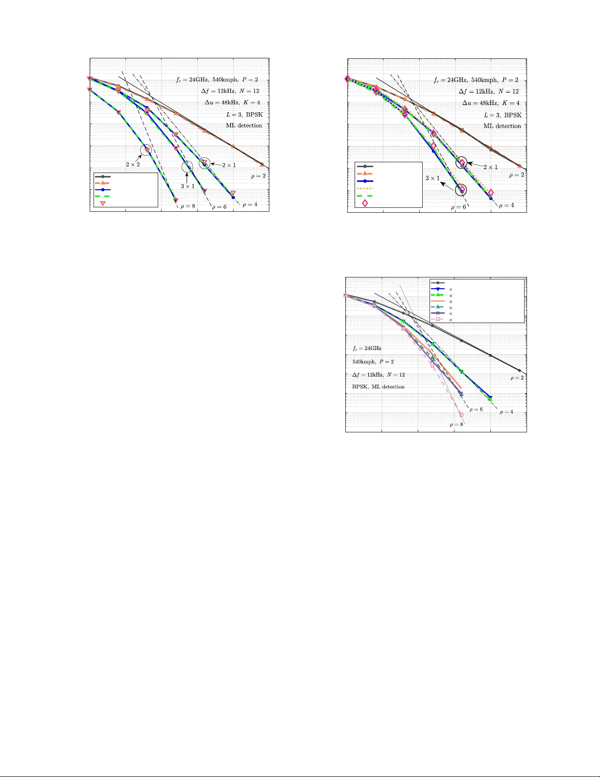
1 Cyclic Delay-Doppler Shift: A Simple T ransmit Di versity T echnique for Ultra-Reliable Communications in Doubly Selecti ve Channels Haoran Y in, Graduate Student Member , IEEE , Y u Zhou, Y anqun T ang, Di Zhang, Senior Member , IEEE , Chi Zhang, Xizhang W ei, Jiaojiao Xiong, Fan Liu, Senior Member , IEEE , Marwa Chafii, Senior Member , IEEE , and M ´ erouane Debbah, F ellow , IEEE Abstract —Affine frequency di vision multiplexing (AFDM) and orthogonal time frequency space (O TFS) ar e two pr omising advanced wav ef orms proposed for reliable communications in high-mobility scenarios. In this paper , we introduce a simple transmit diversity technique, termed cyclic delay-Doppler shift (CDDS), for these two advanced wavef orms to achieve ultra- reliable communications in doubly selective channels (DSCs). T wo simple CDDS schemes, named modulation-domain CDDS (MD-CDDS) and time-domain CDDS (TD-CDDS), are proposed, which perform CDDS in adv ance at the transmitter bef ore and after the modulation, r espectiv ely . W e demonstrate that both of the two proposed CDDS schemes can be implemented efficiently and flexibly by multiplying the transmit vector with a well- designed precoding matrix, which is nothing but a sparse phase- compensated permutation matrix. Moreover , we theoretically and numerically prove that CDDS can pr ovide MIMO-AFDM and MIMO-O TFS with optimal transmit diversity gain when a proper CDDS step is adopted. Compared to the con ventional transmit diversity techniques, the proposed CDDS scheme enjoys the adv antages of lower channel estimation overhead, imple- mentation complexity , and signal processing latency , making it particularly suitable for ultra-reliable communications in high- mobility scenarios. Index T erms —CDDS, transmit diversity , MIMO-AFDM, MIMO-O TFS, doubly selective channels. This work w as supported in part by the Shenzhen Science and T echnology Major Project under Grant KJZD20240903102000001 and in part by the Science and T echnology Planning Project of Ke y Laboratory of Advanced IntelliSense T echnology , Guangdong Science and T echnology Department under Grant 2023B1212060024. An earlier v ersion of this paper w as presented in part at the IEEE International Conference on Acoustics, Speech and Signal Processing (ICASSP) W orkshops 2023 [1]. ( Corresponding author: Y anqun T ang. ) Haoran Y in, Y u Zhou, Y anqun T ang, and Jiaojiao Xiong are with the School of Electronics and Communication Engineering, Sun Y at-sen University , Shenzhen, China, and also with the Guangdong Provincial K ey Laboratory of Sea-Air-Space Communication, Shenzhen, China (e-mail: { yinhr6@mail2, zhouy633@mail2, tangyq8@mail, xiongjj7@mail2 } .sysu.edu.cn); Chi Zhang and Xizhang W ei are with the School of Electronics and Communication Engineering, Sun Y at-sen Univ ersity , Shenzhen, China (e- mail: { zhangch397@mail2, weixzh7@mail } .sysu.edu.cn). Di Zhang is with the School of Intelligent Systems Engineering, Sun Y at- sen University , Shenzhen, China (e-mail: zhangd263@mail.sysu.edu.cn). Fan Liu is with the National Mobile Communications Research Laboratory , Southeast University , Nanjing, China (e-mail: fan.liu@seu.edu.cn). Marwa Chafii is with the Wireless Research Lab, Engineering Division, New Y ork Univ ersity (NYU) Abu Dhabi, Abu Dhabi, U AE, and also with NYU WIRELESS, NYU T andon School of Engineering, New Y ork, USA (e-mail: marwa.chafii@nyu.edu). M ´ erouane Debbah is with the Electrical Engineering and Computer Science, Khalifa Univ ersity of Science and T echnology , Abu Dhabi, UAE (e-mail: merouane.debbah@ku.ac.ae). I . I N T R O D U C T I O N The next-generation wireless networks (NGWNs) are con- ceiv ed to support ultra-reliable, high-efficiency , and lo w- latency communication in high-mobility scenarios, including vehicle-to-v ehicle (V2V), unmanned aerial vehicles (UA Vs), and satellite networks [2]. The underlying multipath wireless channels in these advanced applications exhibit prominent Doppler effect due to their high-mobility nature, resulting in both time selectivity and frequency selectivity . In particular , Doppler shifts greatly impair the orthogonality among the subcarriers in con ventional orthogonal frequency division mul- tiplexing (OFDM) wav eform at the receiv er [3]. Considering that higher frequenc y bands will be adopted in NGWNs and Doppler shifts scale linearly with the carrier frequency , designing a new waveform to better adapt to the doubly selectiv e channels (DSCs) is of extreme importance. Against this background, one of the most promising alter- nativ es is delay-Doppler (DD) wa veforms, such as orthogonal time frequenc y space (OTFS) [4], [5], Zak-O TFS [6], and orthogonal delay-Doppler division multiplexing (ODDM) [7]. The core principle of O TFS is modulating information symbols in the DD domain by exploring the two-dimensional sym- plectic finite F ourier transform (SFFT). Since the DD domain channel representation of the DSCs is much sparser and more stationary than the con ventional time-frequency (TF) domain in OFDM, O TFS is resilient to the high DD shifts and is sho wn to significantly outperform OFDM in terms of bit error ratio (BER) [8]–[10]. Recently , another promising candidate named affine fre- quency di vision multiplexing (AFDM) was proposed, attract- ing substantial attention [11]–[17]. Information symbols in AFDM are multiplex ed on a set of orthogonal chirps via the in verse discr ete affine F ourier transform (D AFT) [18], which is characterized by two fundamental parameters that render AFDM compelling flexibility . By appropriately tuning the chirp slopes of the chirp subcarriers according to the Doppler profile of the DSC, AFDM manages to separate all propagation paths with distinct delay or Doppler shifts in the underlying one-dimensional DAFT domain, which guarantees optimal diversity gain in DSCs. In particular , the D AFT - domain channel representation in AFDM exhibits similar sta- bility , sparsity , and separability as the DD-domain counterpart in O TFS, facilitating the channel estimation [19]–[21] and 2 signal detection [22]–[24] of AFDM in DSCs. Extensiv e research has been conducted to explore the potential of AFDM in low-complexity modulation [25], [26], pulse shaping [27], multiple access [12], [28], [29], and integrated sensing and communications (ISAC) [30]–[36], and physical-layer security [37]–[40]. The div ersity order of a wav eform is a ke y indicator of its capacity to support reliable communications. It is mathemati- cally defined as the negati ve slope of the curve of BER versus signal-to-noise ratio (SNR) on a logarithmic scale, character- izing the rate at which the BER decreases as SNR increases. One effecti ve approach to increase the di versity order is to explore the space dimension by le veraging the multiple-input multiple-output (MIMO) techniques, which will continue to play a crucial role in NGWNs. Extensive works on MIMO- AFDM and MIMO-O TFS hav e been conducted, including channel estimation [19], [41], signal detection [42]–[44], and ISA C [45], [46]. In particular , the authors in [8] and [19] demonstrated that optimal receiv e div ersity gain equiv alent to the number of receiv e antennas (RAs) can be straightforwardly obtained in MIMO-AFDM and MIMO-O TFS by simply apply- ing joint-receive-antenna signal detection. Howe ver , compared to the receiv e div ersity , the acquisition of transmit div ersity in MIMO-AFDM and MIMO-O TFS is of great challenge. The classic Alamouti space-time coding (STC) transmit div ersity technique initially proposed for single-carrier modu- lation in [47] receiv ed considerable extensions in the last two decades. It encodes multiple symbols across multiple transmit antennas (T As) ov er multiple time slots, leveraging time diver - sity and ensuring simple linear decoding in MIMO systems. Furthermore, the adaptation of Alamouti STC to MIMO-OTFS systems with two T As was first in vestigated in [48], where the transmit di versity gain was shown to be two. Howe ver , it requires strict cooperation between two consecuti ve frames and assumes that the DSC remains unchanged, which is im- practical in high-mobility scenarios. T o address this limitation, the authors in [49] divided the O TFS frame along the delay domain into two equi valent parts so that the Alamouti STC can be performed within a single transmit frame. Nev ertheless, the extra guard symbols needed for frame di vision incur severe spectral efficiency degradation. Similar challenges arise when applying Alamouti STC to MIMO-AFDM, indicating that Alamouti STC may not be an appropriate choice for MIMO- AFDM and MIMO-O TFS to acquire transmit diversity gain in DSCs. In addition to Alamouti STC, the cyclic delay di versity (CDD) [50], [51] and discontinuous Doppler diversity (DDoD) [52], [53] are two prominent transmit di versity schemes. Specifically , CDD applies fixed cyclic delay shifts to the transmitted signal at multiple T As to obtain delay diversity , whereas DDoD performs fixed Doppler shifts to obtain the Doppler div ersity . Despite the attractiv e characteristics of low complexity and high effecti veness of CDD and DDoD, most of the works of CDD and DDoD mainly focused on MIMO- OFDM in frequency-selectiv e channels, and their design prin- ciples and conclusions cannot be directly e xtended to adv anced wa veforms in DSCs. Insightfully , the authors in [54] prelim- inarily combined CDD with MIMO-O TFS, achie ving notable improv ement in BER compared to single-input single-output (SISO) O TFS thanks to OTFS’ s inherent capability to harvest delay-domain div ersity . Although CDD and DoDD cannot guarantee optimal diversity gain equi valent to the number of T As for MIMO-AFDM and MIMO-O TFS, their natural compatibility with these two wav eforms shows great potential in enabling ultra-reliable communications in DSCs. In this paper , motiv ated by the inborn capability of AFDM and O TFS to gather DD-domain diversity , we introduce a nov el transmit diversity scheme, termed cyclic delay-Doppler shift (CDDS), for MIMO-AFDM and MIMO-OTFS to achie ve ultra-reliable communications in DSCs. The core idea of CDDS is performing dedicated cyclic DD shifts in advance at different T As according to the DD profile of the DSC to effec- tiv ely augment the number of propagation paths of the wireless channel. Specifically , we propose two types of CDDS, which can provide optimal transmit di versity gain for MIMO-AFDM and MIMO-O TFS with appropriate CDDS configurations. W e demonstrate with rigorous deriv ation that both CDDS schemes can be implemented by simply multiplying the transmit vec- tor with a well-designed CDDS precoding matrix, which is nothing but a sparse, phase-compensated permutation matrix. Moreov er , the multiple-T A system with CDDS is equiv alent to a single-T A system, which significantly reduces the channel estimation overhead. Additionally , CDDS is performed within a single transmit frame and requires no additional processing at the receiver , which brings in the advantages of lo wer implementation complexity and signal processing latency . Our contributions are summarized as follows. • W e propose two types of CDDS, namely modulation- domain CDDS (MD-CDDS) and time-domain CDDS (TD-CDDS), which conduct CDDS before and after modulation, respectiv ely . In particular , we deri ve the cor- responding precoding matrices, noting that the TD-CDDS precoding matrix is suitable for all wav eforms, whereas the MD-CDDS precoding matrix should be customized according to the input-output relationship (IOR) in the modulation domain of the specific waveform. Moreover , we un veil with a graphic interpretation that the CDDS operation can be considered as effecti vely shifting the channel delay and Doppler shifts, making the multiple T A system with CDDS equiv alent to a single T A system with an increased number of propagation paths. • W e provide a comprehensi ve e valuation of the proposed CDDS schemes. Specifically , we prov e that when all CDDS-shifted DD profiles remain non-ov erlapping, op- timal transmit diversity gain is guaranteed for MIMO- AFDM and MIMO-OTFS. Additionally , we make a full comparison between CDDS and con ventional Alamouti schemes in terms of channel estimation ov erhead, show- ing that CDDS requires much fewer guard symbols, especially when the number of T As is large. Based on that, we re veal that there is a fundamental tradeof f between the achiev ed transmit di versity and the channel estimation ov erhead, and CDDS can achiev e a more compelling balance than con ventional CDD and DDoD schemes thanks to its e xtra degree of freedom that enables 3 more flexible CDDS step selection. • Finally , extensiv e Monte Carlo simulations are conducted to in vestigate the performance of the two proposed CDDS schemes in terms of BER in DSCs with both integer and fractional Doppler shifts. It is shown that both CDDS schemes effecti vely provide MIMO-AFDM and MIMO- O TFS systems with optimal transmit di versity gain and advantage on lo wer channel estimation overhead ov er con ventional transmit diversity schemes. Moreover , the performance of CDDS is robust to the adopted pulse shaping and imperfect channel state information (CSI). The rest of this paper is organized as follo ws. Sec. II revie ws the basic concepts of MIMO-AFDM and MIMO- O TFS systems, which lays the foundations for the demonstra- tion of CDDS in Sec. III. Sec. IV provides a comprehensive in vestigation on the performance of CDDS, which is verified by the numerical results presented in Sec. V. Finally , Sec. VI concludes this paper . Notations: Upper and lower case boldface letters denote matrices and column vectors, respectiv ely; C denotes the set of complex numbers, and C M × N denotes the set of all M × N matrices with complex entries; I N denotes the identity matrix of size N × N ; a ∼ C N ( 0 , N 0 I N ) means that a follo ws the complex Gaussian distribution with zero mean and cov ariance N 0 I N ; diag ( · ) denotes a square diagonal matrix with the elements of the input vector on the main diagonal; ( · ) ∗ , ( · ) H , ( · ) T , and ∥·∥ denote the conjugate, transpose, the Hermitian and the Euclidean norm operations; |·| denotes the absolute value of a complex scalar; ( · ) N denotes the modulus operation with respect to N ; E [ · ] denotes the expectation; Q ( · ) denotes the tail distribution function of the standard normal distribu- tion; vec ( · ) and vec − 1 ( · ) denote the column-wise vectorization and its reverse operation, respectiv ely; card( · ) denotes the cardinality . I I . F U N D A M E N T A L O F M I M O - A F D M A N D M I M O - OT F S In this section, the basic concepts of MIMO-AFDM and MIMO-O TFS from [4], [5], [11], [12] are briefly re vie wed. Fig. 1 shows the general modulation/demodulation block diagrams of MIMO-AFDM and MIMO-O TFS systems. Let x i ( i = 1 , . . . , N t ) and y j ( j = 1 , . . . , N r ) denote the modulation-domain transmitted vector of the i th T A and the modulation-domain recei ved vector of the j th RA, re- spectiv ely , where N t and N r represent the number of T As and RAs, respectiv ely . The modulation domain refers to the domain in which symbols (data, pilot, and guard symbols) are multiplex ed, namely the DAFT domain for AFDM and the DD domain for O TFS. Correspondingly , s i ( i = 1 , . . . , N t ) and d j ( j = 1 , . . . , N r ) represent the time-domain transmit- ted vector of the i th transmit antenna and the time-domain receiv ed vector of the j th recei ve antenna, respectiv ely . A. AFDM Modulation and Demodulation Let x AFDM ∈ A N × 1 denote a vector of N quadrature amplitude modulation (QAM) symbols in the DAFT domain, where N denotes the number of chirp subcarriers, A represents the modulation alphabet. At the transmitter , N -point inv erse M odulat ion Ad d CP . . . . . . Modulation Add CP Remove CP Demodulation Multi - antenna Channel Estimation & Signal Detect ion Remove CP Demodulation . . . . . . Doubly S elec ti ve C hannel . . . . . . Modulation D om ai n Time D oma i n Trans m it t er Recei ver Modulation Add CP Remove CP Demodulation ... ... ... ... ... ... Modulation Add CP TD - CDDS Add CP . . . TD - CDDS Add C P . . . Modulation Add C P MD - CD D S Add C P . . . Add CP . . . MD - CDDS M odulat ion Modulation . . . Modulation D om ai n Time D oma i n Modulation D om ai n Time D oma i n M odulat ion Ad d CP . . . . . . Modulation Add CP Remove CP Demodulation Multi - antenna Channel Estimation & Signal Dete ction Remove CP Demodulation . . . . . . Doubly S elec ti ve C hannel . . . . . . Modulation D om ai n Time D oma i n Trans m it t er Recei ver ... ... ... ... Fig. 1. General modulation/demodulation block diagrams of baseband MIMO-AFDM and MIMO-OTFS systems. D AFT is firstly performed on x AFDM to con vert it into the time-domain signal s AFDM as s AFDM [ n ] = 1 √ N N − 1 X m =0 x AFDM [ m ] e j 2 π ( c 2 m 2 + 1 N mn + c 1 n 2 ) , (1) where n denotes the discrete-time domain, m = 0 , · · · , N − 1 denotes the index of AFDM chirp subcarrier , and c 1 and c 2 are two fundamental parameters that determine the chirp slope and the initial phase of all AFDM chirp subcarriers, respectively . Equation (1) can be written in matrix form as s AFDM = Λ H c 1 F H Λ H c 2 x AFDM = A H x AFDM (2) where A = Λ c 2 FΛ c 1 ∈ C N × N represents the D AFT matrix, F is the discrete Fourier transform (DFT) matrix with entries e − j 2 πmn/ N / √ N , Λ c ≜ diag e − j 2 πcq 2 , q = 0 , 1 , . . . , N − 1 is a diagonal matrix. Before transmitting s AFDM into the DSC, a chirp- periodic prefix (CPP) given by s AFDM [ n ] = s AFDM [ n + N ] e − j 2 πc 1 ( N 2 +2 N n ) , (3) n = − L CPP , . . . , − 1 , is appended to s AFDM to combat the multipath effect of the DSCs, where L CPP is the length of the CPP and should be set larger than or equal to the maximum delay spread of the channel. In particular , the CPP simplifies to a con ventional cyclic prefix (CP) in OFDM when 2 N c 1 is an integer and N is ev en, as is considered throughout this paper . After appending a CP , s AFDM is transmitted into the DSC, which can be represented in the DD domain with delay τ and Doppler ν as h ( τ , ν ) = P X i =1 h i δ ( τ − l i ∆ t ) δ ( ν − k i ∆ f ) , (4) where P is the number of propagation paths, h i is the channel gain of the i th path, l i ∈ [0 , l max ] and k i ∈ [ − k max , k max ] are assumed to be integers and represent normalized delay and Doppler shifts, respectiv ely , with l max and k max denoting the maximum normalized delay and Doppler shifts, respectively . Moreov er , ∆ t and ∆ f represent the Nyquist sampling interval and the chirp subcarrier spacing of AFDM, respectively , satisfying ∆ f = 1 N ∆ t . At the receiv er , the CP component of the receiv ed time- domain signal is first remo ved, yielding the CP-free time- domain signal d AFDM as d AFDM [ n ] = P X i =1 h i e j 2 π N k i n s AFDM [( n − l i ) N ] + ˜ w [ n ] , (5) 4 where ˜ w ∼ C N (0 , N 0 ) represents the additiv e white Gaussian noise (A WGN). Equation (5) can be expressed in matrix form as d AFDM = P X i =1 h i ˜ H i s AFDM + w = ˜ Hs AFDM + ˜ w , (6) where w ∼ C N ( 0 , N 0 I N ) is the time-domain noise vector , ˜ H = P P i =1 h i ˜ H i ∈ C N × N denotes the time-domain channel matrix, ˜ H i = ∆ k i N Π l i N represents the time-domain subchannel matrix of the i th path, Π N denotes the N × N forward cyclic- shift matrix gi ven by Π N = 0 · · · 0 1 1 · · · 0 0 . . . . . . . . . . . . 0 · · · 1 0 N × N , (7) Π l i N models the l i delay shift, while the digital frequency shift matrix ∆ k i N ≜ diag e j 2 π N k i n , n = 0 , 1 , . . . , N − 1 models the k i Doppler shift of the channels. Then N -point D AFT is implemented on d AFDM to transform it to the D AFT -domain signal y AFDM as y AFDM [ m ] = 1 √ N N − 1 X n =0 d AFDM [ n ] e − j 2 π ( c 2 m 2 + 1 N mn + c 1 n 2 ) , (8) 0 ≤ m ≤ N − 1 , whose matrix form is given by y AFDM = Λ c 2 FΛ c 1 d AFDM = Ad AFDM . (9) Finally , the IOR of AFDM in the D AFT domain is giv en by [11] y AFDM [ m ] = P X i =1 h i e j 2 π N ( N c 1 l 2 i − m ′ l i + N c 2 ( m ′ 2 − m 2 )) x AFDM [ m ′ ] + w [ m ] , m ′ = ( m + ind i ) N , (10) with index indicator of the i th path ind i ≜ (2 N c 1 l i − k i ) N , w [ m ] being the D AFT -domain A WGN. Notably , Equation (10) indicates that the DSC induces D A TF-domain symbol spreading at the receiv er . The matrix form of (10) can be obtained by substituting (2) and (6) into (9) as y AFDM = P X i =1 h i H AFDM i x AFDM + w = H AFDM x AFDM + w , (11) where H AFDM i = A ˜ H i A H denotes the DAFT -domain sub- channel matrix of the i th path, H AFDM = P P i =1 h i H AFDM i is the D AFT -domain channel matrix, w ∼ C N ( 0 , N 0 I N ) is the D AFT -domain noise vector . Remark 1. It has been prov en in [11] (Theorem 1) that the div ersity order of SISO-AFDM ρ SISO-AFDM = P , i.e., SISO- AFDM can achie ve optimal div ersity in DSCs as long as c 1 = 2( k max + k space ) + 1 2 N , (12) c 2 is set as either an arbitrary irrational number or a rational number sufficiently smaller than 1 2 N (spacing factor k space is a non-negati ve integer and will be illustrated later in Sec. III-B), and N ≥ ( l max + 1) (2 ( k max + k space ) + 1) . (13) B. O TFS Modulation and Demodulation Let X O TFS ∈ A K × L denote a matrix of K L QAM symbols in the DD domain, where L and K denote the number of samples in the delay and Doppler dimensions, respectiv ely . For ease of fair comparison between AFDM and O TFS, K L is set to N and the same Nyquist sampling interval is adopted, which guarantees that the two systems occupy the same TF resource. At the transmitter , K L information symbols X O TFS are firstly mapped to TF domain via in verse SFFT as Q O TFS [ n, u ] = 1 √ K L K − 1 X k =0 L − 1 X l =0 X O TFS [ k , l ] e j 2 π ( nk K − ul L ) , (14) where k = 0 , . . . , K − 1 , l = 0 , . . . , L − 1 , n = 0 , . . . , K − 1 , and u = 0 , . . . , L − 1 denote the indices of the Doppler , delay , time, and frequency domain, respecti vely . Then the TF symbols Q O TFS are mapped to the time domain through Heisenberg transform as s O TFS ( t ) = K − 1 X n =0 L − 1 X u =0 Q O TFS [ n, u ] g tx ( t − nT ) e j 2 πu ∆ u ( t − nT ) , (15) where T = L ∆ t , ∆ u = K ∆ f , g tx ( t ) denotes the transmit pulse filter . After passing through the same DSC described in (4), we hav e the received time-domain signal giv en by d O TFS ( t ) = P X i =1 h i e j 2 πk i ∆ f t s ( t − l i ∆ t ) + w ( t ) , (16) which is conv erted to the TF domain with Wigner transform as G O TFS [ n, u ] = Z d O TFS ( t ) g ∗ rx ( t − nT ) e − j 2 πu ∆ u ( t − nT ) dt, (17) where g rx ( t ) is the receive pulse filter . Then, G O TFS is mapped back to DD-domain symbols with SFFT transform, which is giv en by Y O TFS [ k , l ] = 1 √ K L K − 1 X n =0 L − 1 X u =0 G O TFS [ n, u ] e − j 2 π ( nk K − ul L ) . (18) Finally , the IOR of O TFS with bi-orthogonal transmit and receiv e pulses 1 in the DD domain is given by [4] Y O TFS [ k , l ] = P X i =1 h i e − j 2 π k i l i K L X O TFS [( k − k i ) K , ( l − l i ) L ] + w [ k , l ] , (19) 1 Ideal bi-orthogonal transmit and receiv e pulses are used for ease of deriv ation. Howev er, practical rectangular transmit and receiv e pulse filters are considered in the simulation part to demonstrate the robustness of the proposed schemes [55]–[57]. 5 where w [ k, l ] represents the DD-domain A WGM. Notably , Equation (19) indicates that the DSC induces DD-domain symbol spreading at the receiver . Remark 2. It has been prov en in that [8] O TFS attains nearly optimal diversity , i.e., ρ SISO-O TFS ≈ P , in DSCs in the finite SNR region when the frame size K L is sufficiently large. C. MIMO-AFDM and MIMO-O TFS Systems The noise-free time-domain matrix form of the IOR between all T As and the r th RA in MIMO-AFDM and MIMO-O TFS can be denoted as d r = ˜ H r, 1 s 1 + ˜ H r, 2 s 2 + · · · + ˜ H r,N t s N t , (20) where ˜ H r,t = P X i =1 h [ r,t ] i ˜ H [ r,t ] i = P X i =1 h [ r,t ] i ∆ k i N Π l i N (21) is the time-domain channel matrix between the r th RA and the t th T A, ˜ H [ r,t ] i and h [ r,t ] i are the associated time-domain subchannel matrix and the channel gain of the i th path, re- spectiv ely . Moreo ver , the noise-free modulation-domain matrix form IOR can be denoted as y r = H r, 1 x 1 + H r, 2 x 2 + · · · + H r,N t x N t , (22) where H r,t = P P i =1 h [ r,t ] i H [ r,t ] i represents the modulation- domain channel matrix (e.g., H AFDM in (11) for AFDM) between the r th RA and the t th T A, and H [ r,t ] i is the associated modulation-domain subchannel matrix of the i th path. When each T A transmits independent information symbols, i.e., x 1 = x 2 = . . . = x N t , MIMO systems e xplore the transmit multiplexing gain for linear increment in spectral efficienc y with the number of T As and the optimal receive div ersity gain with the number of RAs. Instructiv ely , the multiple T As can also be lev eraged to obtain transmit diversity gain by performing dedicated precoding on fewer symbols at multiple T As, as is applied in the follo wing proposed CDDS scheme, trading multiplexing gain (spectral efficiency) for div ersity gain (reliability). I I I . C Y C L I C D E L A Y - D O P P L E R S H I F T In this section, we propose TD-CDDS and MD-CDDS schemes for MIMO-AFDM and MIMO-O TFS, le veraging their optimal div ersity properties to acquire transmit div ersity gain. A detailed performance analysis will be provided in the next section. A. TD-CDDS W e first introduce the TD-CDDS scheme, whose block diagram is shown in Fig. 2. TD-CDDS is implemented after modulation at the transmitter with N t T As. Let x represent the modulation-domain information vector to be transmitted and s represent the CP-free transmitted time-domain v ector after modulation. At the t th T A ( t = 2 , · · · , N t ), we perform ˜ l t -step cyclic delay shift and ˜ k t -step cyclic Doppler shift on Modulation Add CP . . . . . . Modulation Add CP Remove CP Demodulation M ulti - ant enna Channel Estimation & Signal Detect ion Remove CP Demodulation . . . . . . Doubly S elec ti ve C hannel . . . . . . Modulation D om ai n Time D oma i n Trans m it t er Recei ver Modulation Add CP Remove CP Demodulation ... ... ... ... ... ... Modulation Add CP TD - CDDS Add CP . . . TD - CDDS Add C P . . . Modulation Add C P MD - CDDS Add C P . . . Add CP . . . MD - CDDS Modulation Modulation . . . Modulation D om ai n Time D oma i n Modulation D om ai n Time D oma i n Fig. 2. Block diagrams of the transmitter in a TD-CDDS system. s , referred to as [ ˜ k t , ˜ l t ] -step TD-CDDS, by multiplying s with Π ˜ l t N and ∆ ˜ k t N successiv ely as s [ ˜ k t , ˜ l t ] = ∆ ˜ k t N Π ˜ l t N s = C [ ˜ k t , ˜ l t ] TD-CDDS s , (23) with C [ ˜ k t , ˜ l t ] TD-CDDS = ∆ ˜ k N Π ˜ l N being the [ ˜ k t , ˜ l t ] -step TD-CDDS precoding matrix. Then after adding a CP , s [ ˜ k t , ˜ l t ] is transmitted into the DSC at the t th T A. Based on that, by substituting s , s [ ˜ k 2 , ˜ l 2 ] , . . . , s [ ˜ k N t , ˜ l N t ] into s 1 , s 2 , . . . , s N t in (20), respectively , we have the recei ved time- domain signal at the r th RA as d r = ˜ H r, 1 s | {z } d r, 1 + ˜ H r, 2 s [ ˜ k 2 , ˜ l 2 ] | {z } d r, 2 + · · · + ˜ H r,N t s [ ˜ k N t , ˜ l N t ] | {z } d r,N t , (24) where d r,t ( t = 1 , . . . , N t ) is the component come from the t th T A and can be rewritten according to (21) and (23) as d r,t = ˜ H r,t C [ ˜ k t , ˜ l t ] TD-CDDS s = P X i =1 h [ r,t ] i ∆ k i N Π l i N ∆ ˜ k t N Π ˜ l t N s (25) = P X i =1 h [ r,t ] i e − j 2 π N ˜ k t l i ∆ k i N ∆ ˜ k t N Π l i N Π ˜ l t N s (26) = P X i =1 ¯ h [ r,t ] i ∆ ¯ k [ t ] i N Π ¯ l [ t ] i N s (27) = P X i =1 ¯ h [ r,t ] i ˜ ¯ H [ r,t ] i s = ˜ ¯ H r,t s , (28) where the deriv ation from (25) to (26) is based on the f act that Π l i N ∆ ˜ k t N = e − j 2 π N ˜ k t l i ∆ ˜ k t N Π l i N , ¯ h [ r,t ] i = h [ r,t ] i e − j 2 π N ˜ k t l i , ¯ k [ t ] i = k i + ˜ k t , and ¯ l [ t ] i = l i + ˜ l t represent the effecti ve channel gain, Doppler shift and delay shift of the i th path between the r th RA and the t th T A after [ ˜ k t , ˜ l t ] -step TD- CDDS, respectiv ely , ˜ ¯ H [ r,t ] i and ˜ ¯ H r,t = P P i =1 ¯ h [ r,t ] i ˜ ¯ H [ r,t ] i are the associated effecti ve time-domain subchannel matrix and channel matrix, respectively . Subsequently , substituting (28) into (24), we have d r = ˜ ¯ H r, 1 s + ˜ ¯ H r, 2 s + · · · + ˜ ¯ H r,N t s = N t X t =1 ˜ ¯ H r,t s = ˜ ¯ H r s (29) 6 Modulation Add CP . . . . . . Modulation Add CP Remove CP Demodulation M ulti - ant enna Channel Estimation & Signal Detect ion Remove CP Demodulation . . . . . . Doubly S elec ti ve C hannel . . . . . . Modulation D om ai n Time D oma i n Trans m it t er Recei ver Modulation Add CP Remove CP Demodulation ... ... ... ... ... ... Modulation Add CP TD - CDDS Add CP . . . TD - CDDS Add C P . . . Modulation Add C P MD - CDDS Add C P . . . Add CP . . . MD - CDDS Modulation Modulation . . . Modulation D om ai n Time D oma i n Modulation D om ai n Time D oma i n Fig. 3. Block diagrams of the transmitter in an MD-CDDS system. where ˜ ¯ H r = P N t t =1 ˜ ¯ H r,t . Remark 3. Equation (27) shows that the TD-CDDS operation on s in (23) is equiv alent to shifting the delay and Doppler shifts of all the original propagation paths simultaneously by ˜ l t and ˜ k t , respectively 2 . Since (23) is performed in the time domain, we refer to it as TD-CDDS, which can be considered as the generalization of CDD and DDoD from the frequency- selectiv e channels to the DSCs. Moreover , we can observe from (29) that the MIMO system developed in (20) essentially turns into an equiv alent single-input multiple-output (SIMO) system after TD-CDDS, where ˜ ¯ H r serves as the equi valent time-domain channel matrix between the equiv alent single T A and the r th RA. B. MD-CDDS W e next illustrate the implementation of MD-CDDS in MIMO-O TFS and MIMO-AFDM systems. Dif ferent from TD- CDDS, MD-CDDS is performed before the modulation, as shown in Fig. 3. 1) MD-CDDS-O TFS : Let x O TFS = vec ( X O TFS ) , then the ˜ l t -step cyclic delay shift of X O TFS can be obtained with vec − 1 ( Π K ∗ ˜ l t K L x O TFS ) , and the ˜ k t -step cyclic Doppler shift counterpart can be acquired with vec − 1 (( I L ⊗ Π ˜ k t K ) x O TFS ) , where ⊗ denotes the Kronecker product operation. Therefore, performing [ ˜ k t , ˜ l t ] -step MD-CDDS on X O TFS at the t th T A is equiv alent to multiplying X O TFS with Π K ∗ ˜ l t K L and ( I L ⊗ Π ˜ k K ) successiv ely as X [ ˜ k t , ˜ l t ] O TFS = vec − 1 (( I L ⊗ Π ˜ k K ) Π K ∗ ˜ l t K L x O TFS ) = vec − 1 ( C [ ˜ k t , ˜ l t ] , O TFS MD-CDDS x O TFS ) , (30) where C [ ˜ k t , ˜ l t ] , O TFS MD-CDDS = ( I L ⊗ Π ˜ k K ) Π K ∗ ˜ l t K L (31) is the [ ˜ k t , ˜ l t ] -step MD-CDDS precoding matrix of O TFS. Notably , we have X [ ˜ k t , ˜ l t ] O TFS [ k , l ] = X O TFS [( k − ˜ k t ) K , ( l − ˜ l t ) L ] . (32) 2 This is also feasible for AFDM with a CPP that cannot be simplified to a CP by simply performing phase compensation according to the extra phase in the CPP provided in (3) and the adopted CDDS step. Consequently , the noise-free IOR of O TFS in (19) becomes Y [ r,t ] O TFS [ k , l ] = P X i =1 h [ r,t ] i e − j 2 π k i l i K L X [ ˜ k t , ˜ l t ] O TFS [( k − k i ) K , ( l − l i ) L ] (32) = P X i =1 h [ r,t ] i e j 2 π k i ˜ l t + ˜ k t l i + ˜ k t ˜ l t K L e − j 2 π ( k i + ˜ k t )( l i + ˜ l t ) K L × X O TFS [( k − ( k i + ˜ k t )) K , ( l − ( l i + ˜ l t )) L ] = P X i =1 ¯ h [ r,t ] i, O TFS e − j 2 π ¯ k [ t ] i ¯ l [ t ] i K L X O TFS [( k − ¯ k [ t ] i ) K , ( l − ¯ l [ t ] i ) L ] , (33) where Y [ r,t ] O TFS is the receiv ed DD-domain symbol matrix of the r th RA that contributed by the t th T A, ¯ h [ r,t ] i, O TFS = h [ r,t ] i e j 2 π k i ˜ l t + ˜ k t l i + ˜ k t ˜ l t K L , ¯ k [ t ] i = k i + ˜ k t , and ¯ l [ t ] i = l i + ˜ l t represent the effecti ve channel gain, Doppler shift and delay shift of the i th path between the r th RA and the t th T A after [ ˜ k t , ˜ l t ] -step MD-CDDS, respecti vely . 2) MD-CDDS-AFDM : For AFDM with the parameter set- ting of (12), a full DD representation can be obtained, i.e., all the paths can be sufficiently separated in the D AFT domain [11]. Fig. 4 demonstrates the bijectiv e relationship between the DD-domain and D AFT -domain channel representations in O TFS and AFDM, where the latter can be considered as splicing multiple [2( k max + k space )+ 1] -length delay blocks with each delay block is separated from its adjacence by two k space - length spacing band. Insightfully , this bijecti ve relationship indicates that a unit Doppler shift results in a unit cyclic shift in the D AFT domain, whereas a unit delay shift corresponds to a ( − [2( k max + k space ) + 1]) -step cyclic shift in the D AFT domain [12]. This property aligns with the D AFT -domain symbol spreading demonstrated in the AFDM IOR in (10). Consequently , [ ˜ k t , ˜ l t ] -step MD-CDDS in AFDM corresponds to performing ˜ m t -step shifts in the DAFT domain, where ˜ m t = ˜ k t − [2( k max + k space ) + 1] ˜ l t = ˜ k t − 2 N c 1 ˜ l t . (34) Besides, to ensure that the indices of the ne w paths after cyclic Doppler shifts remain in the original delay blocks, the parameter k space in c 1 should satisfy k space ≥ max { k max , k 2 , max , . . . , k N t , max } − k max , (35) where k t, max ≜ max {| k 1 + ˜ k t | , . . . , | k P + ˜ k t |} , t = 2 , . . . , N t (36) denotes the effecti ve maximum Doppler after ˜ k t -step c yclic Doppler shift. Building on these insights, we proceed to deriv e the MD- CDDS matrix of AFDM. T o this end, we first multiple x AFDM with Π ˜ m t N to perform ˜ m t -step cyclic D AFT -domain shift as x [ ˜ m t ] AFDM = Π ˜ m t N x AFDM , (37) which implies that x [ ˜ m t ] AFDM [ m ] = x AFDM [( m − ˜ m t ) N ] . (38) 7 DD Domain DAFT Domain ... ... ... Delay Do ppler 0 1 0 1 2 - 1 - 2 0 1 2 - 1 - 2 0 1 2 - 1 - 2 Delay block with = 1 Delay block with = 1 Delay block with = 0 Delay block with = 0 Fig. 4. The bijective relation between DD-domain (left) and DAFT -domain (right) channel representations ( k max = 2 and k space = 1 ). Then the noise-free IOR in (10) conv erts to (40) (sho wn at the top of the next page), where y [ r,t ] AFDM is the received D AFT - domain symbol of the r th RA that contributed by the t th T A. Substituting (38) into (40), we hav e (41). Let ¯ m = ( m ′ − ˜ m t ) N , we obtain m ′ = ( ¯ m + ˜ m t ) N , which yields (42), where ¯ m = (( m + ind i ) N − ˜ m t ) N = ( m + 2 N c 1 l i − k i − ( ˜ k t − 2 N c 1 ˜ l t )) N = ( m + 2 N c 1 ( l i + ˜ l t ) − ( k i + ˜ k t )) N = ( m + ¯ ind [ t ] i ) N (39) and ¯ ind [ t ] i ≜ (2 N c 1 ¯ l [ t ] i − ¯ k [ t ] i ) N is the ef fective index indicator of the i th path. After some algebraic manipulations, we arriv e at (43), where A ( l i , ˜ m t ) = e − j 2 π N ( N c 1 (2 l i ˜ l t + ˜ l 2 t )+ ˜ m t l i ) (44) and E ( ¯ m, ˜ m t ) = e j 2 π N ( ¯ m ˜ l t + N c 2 ( ( ¯ m + ˜ m t ) 2 N − ¯ m 2 )) . (45) It is important to notice that E ( m ′ , ˜ m t ) has no relev ance to the channel parameters h i , l i , and k i and receiv ed DAFT -domain index m , which means we can compensate it in advance at the transmitting end by multiplying x AFDM with a phase compensation matrix P [ ˜ m t ] N = diag ( E ∗ ( ¯ m, ˜ m t ) , ¯ m = 0 , 1 , . . . , N − 1) (46) before performing ˜ m t -step cyclic D AFT -domain shift. By doing so, (43) can be further simplified as (47), where ¯ h [ r,t ] i, AFDM = h [ r,t ] i A ( l i , ˜ m t ) is the effecti ve channel gain of the i th path between the r th RA and the t th T A after [ ˜ k t , ˜ l t ] -step MD-CDDS in AFDM. Therefore, we hav e the final [ ˜ k t , ˜ l t ] -step MD-CDDS precoding matrix of AFDM as C [ ˜ k t , ˜ l t ] , AFDM MD-CDDS = Π ˜ m t N P [ ˜ m t ] N , (48) which in volves two procedures of first performing phase compensation and then performing cyclic DAFT -domain shift. T able I summarizes the precoding matrices of [ ˜ k t , ˜ l t ] -step TD- CDDS and MD-CDDS in OTFS and AFDM systems. Remark 4. Comparing (33) and (47) with (19) and (10) correspondingly , we can observe that MD-CDDS can also be considered as shifting the delay and Doppler shifts of all the original propagation paths simultaneously by ˜ l t and ˜ k t , respectiv ely 3 . 3 Since Equation (10) and the deriv ations in (34)-(48) hold for all values of c 1 in AFDM, the proposed MD-CDDS scheme is also feasible for AFDM with a CPP that cannot be simplified to a CP . T ABLE I [ ˜ k t , ˜ l t ] - S T E P T D - CD D S A N D M D - C DD S P R E C OD I N G M ATR I C E S O F OT F S A N D A F D M TD-CDDS (Eq. 23) C [ ˜ k t , ˜ l t ] TD-CDDS = ∆ ˜ k N Π ˜ l N MD-CDDS-O TFS (31) C [ ˜ k t , ˜ l t ] , OTFS MD-CDDS = ( I L ⊗ Π ˜ k K ) Π K ∗ ˜ l t K L MD-CDDS-AFDM (48) C [ ˜ k t , ˜ l t ] , AFDM MD-CDDS = Π ˜ m t N P [ ˜ m t ] N Furthermore, substituting x , x [ ˜ k 2 , ˜ l 2 ] , . . . , x [ ˜ k N t , ˜ l N t ] into x 1 , x 2 , . . . , x N t in (22), respecti vely , where x [ ˜ k t , ˜ l t ] = C [ ˜ k t , ˜ l t ] x , C [ ˜ k t , ˜ l t ] is the [ ˜ k t , ˜ l t ] -step MD-CDDS precoding ma- trix of the adopted wa veform ( C [ ˜ k t , ˜ l t ] , AFDM MD-CDDS and C [ ˜ k t , ˜ l t ] , O TFS MD-CDDS for AFDM and OTFS, respectiv ely), we ha ve the receiv ed modulation-domain signal at the r th RA as y r = H r, 1 x + H r, 2 x [ ˜ k 2 , ˜ l 2 ] + · · · + H r,N t x [ ˜ k N t , ˜ l N t ] = H r, 1 x + H r, 2 C [ ˜ k 2 , ˜ l 2 ] | {z } ¯ H r, 2 x + · · · + H r,N t C [ ˜ k N t , ˜ l N t ] | {z } ¯ H r,N t x = ¯ H r x , (49) where ¯ H r,t = H r,t C [ ˜ k t , ˜ l t ] is the effecti ve modulation-domain channel matrix between the r th RA and the t th T A after [ ˜ k t , ˜ l t ] - step MD-CDDS, ¯ H r = ( H r, 1 + ¯ H r, 2 + · · · + ¯ H r,N t ) . This indicates that the MIMO system de veloped in (22) can also be vie wed as an equi valent SIMO system after MC-CDDS, where ¯ H r serves as the equi valent modulation-domain channel matrix between the equiv alent single T A and the r th RA. C. Graphic Interpr etation of CDDS W e further provide a graphic interpretation of the principle CDDS in the sequel, as shown in Fig. 5 (sho wn at the top of the next page). Assume that there are two paths in the original DSC between the transmitter and recei ver , as indicated by “ ” and “ △ ”, respecti vely , and the transmitter is equipped with six T As. Then, the effecti ve channels that after { [-1, 0], [1, 0], [-1, 1], [0, 1], [1, 1] } -step CDDS are provided, respectiv ely , which are associated with ˜ ¯ H r,t from (28) in the time domain and ¯ H r,t from (49) in the modulation domain, where the corresponding effecti ve paths are highlighted with different colors. Based on that, the equiv alent 12-path channel of the equiv alent SIMO system can be obtained, which is associated with ˜ ¯ H r from (29) in the time domain and ¯ H r from (49) in the modulation domain. Notably , as will be illustrated in Sec. IV -B, this equiv alent single-T A characteristic in CDDS will significantly reduce channel estimation overhead compared to con ventional MIMO-AFDM and MIMO-O TFS systems that require estimating a total of N t N r DSCs across all pairs of T A and RA. Moreov er , it is worth mentioning that, although the ef fectiv e maximum delay is enlarged, the required length of CP remains unchanged, given that the delay shifts are performed cyclically in both time and modulation domains. D. Comparison between TD-CDDS and MD-CDDS From the viewpoint of the ultimate effect, the difference between TD-CDDS and MD-CDDS lies in the extra complex 8 y [ r,t ] AFDM [ m ] = P X i =1 h [ r,t ] i e j 2 π N ( N c 1 l 2 i − m ′ l i + N c 2 ( m ′ 2 − m 2 )) x [ ˜ m t ] AFDM [ m ′ ] , m ′ = ( m + ind i ) N (40) (38) = P X i =1 h [ r,t ] i e j 2 π N ( N c 1 l 2 i − m ′ l i + N c 2 ( m ′ 2 − m 2 )) x AFDM [( m ′ − ˜ m t ) N ] , m ′ = ( m + ind i ) N (41) = P X i =1 h [ r,t ] i e j 2 π N ( N c 1 l 2 i − ( ¯ m + ˜ m t ) N l i + N c 2 ( ( ¯ m + ˜ m t ) 2 N − m 2 )) x AFDM [ ¯ m ] , ¯ m = ( m + ¯ ind [ t ] i ) N (42) = P X i =1 h [ r,t ] i e j 2 π N ( − N c 1 (2 l i ˜ l t + ˜ l 2 t )+( ¯ m − ( ¯ m + ˜ m t ) N ) l i + ¯ m ˜ l t + N c 2 ( ( ¯ m + ˜ m t ) 2 N − ¯ m 2 )) × e j 2 π N ( N c 1 ( l i + ˜ l t ) 2 − ¯ m ( l i + ˜ l t )+ N c 2 ( ¯ m 2 − m 2 )) x AFDM [ ¯ m ] , ¯ m = ( m + ¯ ind [ t ] i ) N = P X i =1 h [ r,t ] i e − j 2 π N ( N c 1 (2 l i ˜ l t + ˜ l 2 t )+ ˜ m t l i ) | {z } A ( l i , ˜ m t ) e j 2 π N ( ¯ m ˜ l t + N c 2 ( ( ¯ m + ˜ m t ) 2 N − ¯ m 2 )) | {z } E ( ¯ m, ˜ m t ) × e j 2 π N N c 1 ( ¯ l [ t ] i ) 2 − ¯ m ¯ l [ t ] i + N c 2 ( ¯ m 2 − m 2 ) x AFDM [ ¯ m ] , ¯ m = ( m + ¯ ind [ t ] i ) N . (43) y [ r,t ] AFDM [ m ] = P X i =1 ¯ h [ r,t ] i, AFDM e j 2 π N N c 1 ( ¯ l [ t ] i ) 2 − m ′ ¯ l [ t ] i + N c 2 ( m ′ 2 − m 2 ) x AFDM [ ¯ m ] , ¯ m = m + ¯ ind [ t ] i N , 0 ≤ m ≤ N − 1 . (47) DD Domain DAFT Domain ... ... ... Delay Doppler 0 1 0 1 2 - 1 - 2 0 1 2 - 1 - 2 0 1 2 - 1 - 2 Delay block with = 1 Delay block with = 1 Delay block with = 0 Delay block with = 0 [ - 1, 0] - step CDDS [1, 0] - step CDDS [ - 1, 1] - step CDDS [1, 1] - step CDDS [0, 1] - step CDDS Equivalent 12 - path Ch annel O riginal 2 - path Channel [0, 1] - step CDDS [0, 1] - step CDDS [ - 1, 0] - step CDDS [1, 0] - step CDDS Delay Doppler 0 0 1 - 1 2 - 2 1 2 3 4 Delay Doppler 0 0 1 - 1 2 - 2 1 2 3 4 Delay Doppler 0 0 1 - 1 2 - 2 1 2 3 4 Delay Doppler 0 0 1 - 1 2 - 2 1 2 3 4 Delay Doppler 0 0 1 - 1 2 - 2 1 2 3 4 Delay Doppler 0 0 1 - 1 2 - 2 1 2 3 4 Delay Doppler 0 0 1 - 1 2 - 2 1 2 3 4 Fig. 5. An example of the equivalent DD-domain channel after CDDS with six T As. exponentials in the effecti ve channel gains, i.e., ¯ h [ r,t ] i for TD- CDDS in (27), ¯ h [ r,t ] i, O TFS for MD-CDDS-O TFS in (33), and ¯ h [ r,t ] i, AFDM for MD-CDDS-AFDM in (47). Moreover , while TD- CDDS is suitable for all wa veforms, where all wa veforms share the same TD-CDDS precoding matrix, the MD-CDDS precoding matrix should be designed elaborately according to the modulation-domain IOR of the specific wa veform 4 . Furthermore, TD-CDDS only requires one modulation opera- tion, while MD-CDDS requires N t times modulation, which means TD-CDDS enjoys lower complexity . Howe ver , since the CDDS is carried out before modulation in MD-CDDS, it is more feasible for MD-CDDS to combine with other precoding techniques to achieve joint precoding without introducing additional operation ov erhead to the transmitter . 4 Although this paper mainly focuses on AFDM and O TFS, both CDDS schemes can be directly extended to other waveforms that explore multipath for div ersity , such as Zak-O TFS, ODDM, and orthogonal chirp division multiplexing (OCDM). Besides, it is worth emphasizing that the TD-CDDS and MD-CDDS matrices of OTFS and AFDM, namely C [ ˜ k t , ˜ l t ] TD-CDDS , C [ ˜ k t , ˜ l t ] , O TFS MD-CDDS , and C [ ˜ k t , ˜ l t ] , AFDM MD-CDDS , are all sparse phase- compensated permutation matrices, which have no relev ance to the DD profile of the real-time DSCs. It means that the TD- CDDS and MD-CDDS matrices can be calculated only once in advance with relatively low complexity at the transmitter , despite the ev er-changing channels, and the implementation of CDDS only inv olves dot product and cyclic shift. Moreov er, the equi valent single-T A property of CDDS makes it feasible to directly apply low-comple xity signal detectors proposed for SISO systems to CDDS systems [57], which is of extreme significance from the perspectiv e of practical implementation. I V . P E R F O R M A N C E A NA LY S I S O F C D D S In this section, we e valuate the performance of the two proposed CDDS schemes. A. T ransmit Diversity W e first analyze the transmit diversity order of MIMO- AFDM and MIMO-O TFS systems with CDDS. Defining the DD profile of the channel before CDDS as P = { ( k 1 , l 1 ) , · · · , ( k P , l P ) } , then the ef fective DD profile after [ ˜ k t , ˜ l t ] -step CDDS can be denoted as P [ ˜ k t , ˜ l t ] , and the effecti ve DD profile of the equiv alent SIMO system can be represented as ˜ P = P ∪ P [ ˜ k 2 , ˜ l 2 ] ∪ · · · ∪ P [ ˜ k N t , ˜ l N t ] . Then, we have the following proposition. Proposition 1. Optimal transmit diversity gain quivalent to the number of transmit antennas N t can be achie ved by 9 △ △ ... ... ... ▷ ... ▷ ◁ ... ◁ ▲ ▲ ▲ ▲ ▲ ▲ ▲ ▲ ▲ ▲ ▲ ▲ P ▲ ▲ △ △ △ △ △ △ △ △ △ △ △ △ SISO - AFDM CDDS - AFDM MIMO - AFDM Delay block wi th Delay block with Delay block with Delay block with Delay block with Delay block with Delay block with Delay block with Delay block with Delay block wi th OTFS ○ ○ ○ ○ ○ ○ ○ ○ ○ ○ ○ ○ ○ ○ ○ △ △ △ △ △ ◇ ◁ ◁ ▷ ▷ ▷ ○ △ △ △ △ △ ◇ ◁ ◁ ▷ ▷ ▷ ○ △ △ ▲ ▲ ▲ ◇ ◁ ◁ ▷ ▷ ▷ ○ △ △ ▲ ▲ ▲ ◇ ◁ ◁ ▷ ▷ ▷ ○ △ △ P ▲ ▲ ◇ ◁ ◁ ▷ ▷ ▷ ○ △ △ ▲ ▲ ▲ ◇ ◁ ◁ ▷ ▷ ▷ ○ △ △ ▲ ▲ ▲ ◇ ◁ ◁ ▷ ▷ ▷ ○ △ △ △ △ △ ◇ ◁ ◁ ▷ ▷ ▷ ○ △ △ △ △ △ ◇ ◁ ◁ ▷ ▷ ▷ ○ ○ ○ ○ ○ ○ ○ ○ ○ ○ ○ ○ ○ ○ Delay Doppler ○ ○ ○ ○ ○ ○ ○ ○ ○ ○ ○ ○ ○ ○ ○ △ △ △ △ △ ◇ ◁ ◁ ▷ ▷ ▷ ○ △ △ △ △ △ ◇ ◁ ◁ ▷ ▷ ▷ ○ △ △ ▲ ▲ ▲ ◇ ◁ ◁ ▷ ▷ ▷ ○ △ △ ▲ ▲ ▲ ◇ ◁ ◁ ▷ ▷ ▷ ○ △ △ P ▲ ▲ ◇ ◁ ◁ ▷ ▷ ▷ ○ △ △ ▲ ▲ ▲ ◇ ◁ ◁ ▷ ▷ ▷ ○ △ △ ▲ ▲ ▲ ◇ ◁ ◁ ▷ ▷ ▷ ○ △ △ △ △ △ ◇ ◁ ◁ ▷ ▷ ▷ ○ △ △ △ △ △ ◇ ◁ ◁ ▷ ▷ ▷ ○ ○ ○ ○ ○ ○ ○ ○ ○ ○ ○ ○ ○ ○ Delay Doppler Pilot - guard overhead of CDDS - OTFS Pilot - guard overhead of MIMO - OTFS P Channel estimation region of SISO - OTFS and the 1st TA of MIMO - OTFS Effective channel estimation region of CDDS - OTFS △ ◇ ◁ ▲ ▷ ○ + Pilot symbol Guard symbol used for channel estimation in SISO system + ◇ Guard symbol used for data - pilot separation in SISO system Extra guard sy mbol needed in CDD S - based syste m Guard symb ol for channel estim ation of the 2nd TA in MIMO s ystem Guard symb ol for channel estim ation of the 3rd TA in MIMO sy stem Guard symb ol for channel estim ation of the 4th TA in MIMO sy stem Guard symb ol for channel estim ation of the 5th TA in MIMO sy stem Guard symbol for channel estimation of the 6th TA in MIMO system Legend △ △ ○ ○ ○ ○ ○ ○ ○ ○ ... ○ ▲ ▲ ▲ ▲ ▲ ○ ○ ▲ ▲ ▲ ▲ ▲ ○ ○ ▲ ▲ P ▲ ▲ ○ ○ ○ ○ ○ ○ ○ ○ ... ○ △ △ △ △ △ ○ ○ △ △ △ △ △ ○ ○ △ △ △ △ ▲ ▲ ▲ ▲ ▲ ▲ ▲ ▲ ▲ ▲ ▲ ▲ P ▲ ▲ △ △ △ △ △ △ △ △ △ △ △ △ Original channel estimation r egion with size Effective channel estimation r egion after CDDS with size Channel estimation region of the 1st TAwith size Pilot - guard overhead of SISO - OTFS Data symbol △ △ ... ... ... ▷ ... ▷ ◁ ... ◁ ▲ ▲ ▲ ▲ ▲ ▲ ▲ ▲ ▲ ▲ ▲ ▲ P ▲ ▲ △ △ △ △ △ △ △ △ △ △ △ △ SISO - AFDM CDDS - AFDM MIMO - AFDM Delay block wi th Delay block with Delay block with Delay block with Delay block with Delay block with Delay block with Delay block with Delay block with Delay block wi th OTFS ○ ○ ○ ○ ○ ○ ○ ○ ○ ○ ○ ○ ○ ○ ○ △ △ △ △ △ ◇ ◁ ◁ ▷ ▷ ▷ ○ △ △ △ △ △ ◇ ◁ ◁ ▷ ▷ ▷ ○ △ △ ▲ ▲ ▲ ◇ ◁ ◁ ▷ ▷ ▷ ○ △ △ ▲ ▲ ▲ ◇ ◁ ◁ ▷ ▷ ▷ ○ △ △ P ▲ ▲ ◇ ◁ ◁ ▷ ▷ ▷ ○ △ △ ▲ ▲ ▲ ◇ ◁ ◁ ▷ ▷ ▷ ○ △ △ ▲ ▲ ▲ ◇ ◁ ◁ ▷ ▷ ▷ ○ △ △ △ △ △ ◇ ◁ ◁ ▷ ▷ ▷ ○ △ △ △ △ △ ◇ ◁ ◁ ▷ ▷ ▷ ○ ○ ○ ○ ○ ○ ○ ○ ○ ○ ○ ○ ○ ○ Delay Doppler ○ ○ ○ ○ ○ ○ ○ ○ ○ ○ ○ ○ ○ ○ ○ △ △ △ △ △ ◇ ◁ ◁ ▷ ▷ ▷ ○ △ △ △ △ △ ◇ ◁ ◁ ▷ ▷ ▷ ○ △ △ ▲ ▲ ▲ ◇ ◁ ◁ ▷ ▷ ▷ ○ △ △ ▲ ▲ ▲ ◇ ◁ ◁ ▷ ▷ ▷ ○ △ △ P ▲ ▲ ◇ ◁ ◁ ▷ ▷ ▷ ○ △ △ ▲ ▲ ▲ ◇ ◁ ◁ ▷ ▷ ▷ ○ △ △ ▲ ▲ ▲ ◇ ◁ ◁ ▷ ▷ ▷ ○ △ △ △ △ △ ◇ ◁ ◁ ▷ ▷ ▷ ○ △ △ △ △ △ ◇ ◁ ◁ ▷ ▷ ▷ ○ ○ ○ ○ ○ ○ ○ ○ ○ ○ ○ ○ ○ ○ Delay Doppler Pilot - guard overhead of CDDS - OTFS Pilot - guard overhead of MIMO - OTFS P Channel estimation region of SISO - OTFS and the 1st TA of MIMO - OTFS Effective channel estimation region of CDDS - OTFS △ ◇ ◁ ▲ ▷ ○ + Pilot symbol Guard symbol used for channel estimation in SISO system + ◇ Guard symbol used for data - pilot separation in SISO system Extra guard sy mbol needed in CDD S - based syste m Guard symb ol for channel estim ation of the 2nd TA in MIMO s ystem Guard symb ol for channel estim ation of the 3rd TA in MIMO sy stem Guard symb ol for channel estim ation of the 4th TA in MIMO sy stem Guard symb ol for channel estim ation of the 5th TA in MIMO sy stem Guard symbol for channel estimation of the 6th TA in MIMO system Legend △ △ ○ ○ ○ ○ ○ ○ ○ ○ ... ○ ▲ ▲ ▲ ▲ ▲ ○ ○ ▲ ▲ ▲ ▲ ▲ ○ ○ ▲ ▲ P ▲ ▲ ○ ○ ○ ○ ○ ○ ○ ○ ... ○ △ △ △ △ △ ○ ○ △ △ △ △ △ ○ ○ △ △ △ △ ▲ ▲ ▲ ▲ ▲ ▲ ▲ ▲ ▲ ▲ ▲ ▲ P ▲ ▲ △ △ △ △ △ △ △ △ △ △ △ △ Original channel estimation r egion with size Effective channel estimation r egion after CDDS with size Channel estimation region of the 1st TAwith size Pilot - guard overhead of SISO - OTFS Data symbol Fig. 6. Data-pilot-guard symbol arrangement in AFDM and O TFS with SISO, MIMO, and CDDS configurations (six T As). T ABLE II C H AN N E L E S T I MAT IO N O V E R H EA D O F A F D M A N D OT F S S Y ST E M S Configuration W aveform AFDM O TFS SISO [11], [41] 2( l max + 1) 2 k max + 1 − 1 (2 l max + 1)(4 k max + 1) MIMO [19], [41] ( N t + 1)( l max + 1) 2 k max + 1 − 1 N t ( l max + 1) + l max 4 k max + 1 CDD [54] 2( l max + N t )(2 k max + 1) − 1 2( l max + N t − 1) + 1 (4 k max + 1) DoDD 2( l max + 1)(2 k max + N t + 1) − 1 (2 l max + 1)(4 k max + 2 N t + 1) CDDS 2( l max + ˜ l max + 1) 2( k max + ˜ k max ) + 1 − 1 (2( l max + ˜ l max ) + 1)(4( k max + ˜ k max ) + 1) MIMO-AFDM and MIMO-OTFS with CDDS in doubly se- lective channels if P ∩ P [ ˜ k 2 , ˜ l 2 ] ∩ · · · ∩ P [ ˜ k N t , ˜ l N t ] = ∅ and N t P ≤ N . (50) Pr oof. See Appendix A. Insightfully , (50) indicates that to acquire optimal transmit div ersity , one should carefully choose the CDDS steps at all T As so that there is no overlap among the N t effecti ve DD profiles that are associated with the N t T As, as the example shown in Fig. 5 5 . Therefore, we refer to (50) as path non- ov erlap condition. B. EP A Channel Estimation Overhead W e next analyze the channel estimation overhead of CDDS- based AFDM and O TFS systems with embedded pilot-aided (EP A) channel estimation scheme [11], [19], [41]. Fig. 6 (shown on the next page) shows the data-pilot-guard symbol arrangement of AFDM and O TFS with SISO, MIMO, and 5 It was shown in [9], [58] that applying channel coding can potentially improve the ability of OTFS systems to acquire optimal div ersity order . Therefore, CDDS-based MIMO-O TFS can effecti vely achiev e optimal trans- mit diversity gain of N t with channel coding. CDDS configurations. W e can observe that the channel estima- tion ov erhead of CDDS-based AFDM and OTFS systems are much lo wer than the counterparts of the conv entional MIMO- AFDM and MIMO-O TFS systems, whose data-pilot-guard symbol arrangement is adopted by most of the conv entional transmit diversity techniques, e.g., Alamouti STC [48], [49]. This can be attributed to the fact that the CDDS-based system is equiv alent to a SIMO system, which sufficiently explores the channel sparsity and hence only requires a few extra guard symbols compared to the SISO system. In contrast, the con ventional MIMO systems separately estimate the channel parameters between all pairs of T A and RA, which require a significant increase of guard symbols. Furthermore, T able II (shown on the next page) quantifies the pilot-guard overhead of AFDM and O TFS with SISO, MIMO, and CDDS configurations for channel estimation, where ˜ k max ≜ max { k max , k 2 , max , . . . , k N t , max } − k max (51) and ˜ l max ≜ max { ˜ l 2 , . . . , ˜ l N t } represent the maximum extra Doppler shift and maximum cyclic-delay shift, respecti vely , k t, max and ˜ l t are defined in (36) and (23), respectively , k space is set to be ˜ k max , J = ( l max + 1) 2 k max + 1 , and ˜ J = 10 ( l max + ˜ l max + 1) 2( k max + ˜ k max ) + 1 .Notably , the pilot-guard ov erhead of AFDM and O TFS systems with con ventional MIMO, CDD, or DoDD configuration grows linearly with N t . In contrast, the pilot-guard ov erhead of the proposed CDDS scheme exhibits a similar form as the SISO case and thus increases more slo wly with the increase of N t . This sharp distinction will be illustrated in Fig. 12 in Sec. V -B. C. CDDS-Step Selection Criterion Building on the abov e insights, one optimal CDDS-step se- lection strategy is to minimize the channel estimation ov erhead while guaranteeing the optimal transmit di versity . This can be expressed as min ˜ k 2 ,..., ˜ k N t , ˜ l 2 ,..., ˜ l N t O CDDS-AFDM or O CDDS-O TFS s.t. (50) , (52) where notations O CDDS-AFDM and O CDDS-O TFS stand for the channel estimation overhead of CDDS-AFDM and CDDS- O TFS, respectiv ely . In practice, one can flexibly and empirically adjust the CDDS step { ˜ k 2 , . . . , ˜ k N t , ˜ l 2 , . . . , ˜ l N t } through modulation- domain channel prediction to achiev e or approximate (52) giv en that the modulation-domain representations of DSCs in AFDM and O TFS are typically sparse and relativ ely stable. Furthermore, it is worth noting that a low channel estimation ov erhead calls for small ˜ k max and ˜ l max , while the path non-ov erlap condition in (50) prefers lar ge ˜ k max and ˜ l max to accommodate the optimal transmit div ersity requirement. Therefore, there is a natural tradeoff between the channel estimation overhead and the achie vable transmit di versity gain in CDDS-AFDM and CDDS-OTFS systems. D. Advantages over Con ventional Schemes Compared to the classic Alamouti scheme [48], [49], the proposed CDDS not only enjoys a much lower channel esti- mation overhead but also has a more flexible and simple T A and RA management. Specifically , for general Alamouti-based MIMO-O TFS and MIMO-AFDM systems, each data symbol is transmitted in η frames ( η is the transmit di versity order achiev ed), where the precoding operation of each T A v aries when the number of T As changes, and the receiv er should per- form maximal-ratio combining correspondingly . This means that high latency is inevitable, and the receiver should precisely know the number of T As. In contrast, the proposed CDDS scheme is conducted within a single frame, which achiev es much lo wer latency . Moreo ver , increasing or decreasing the number of T As in CDDS only introduces specific changes in the relative T As and the receiv er only needs to know ( l max + ˜ l max ) and ( k max + ˜ k max ) to determine the channel estimation region, which is much simpler than the Alamouti scheme. Furthermore, compared to the con ventional CDD and DDoD schemes, CDDS possesses a higher degree of flexibility thanks to an extra degree of freedom to perform cyclic shift, which enables it to achiev e a more compelling tradeoff between transmit div ersity and channel estimation overhead. Besides, 0 5 10 15 20 25 SNR in dB 10 -7 10 -6 10 -5 10 -4 10 -3 10 -2 10 -1 10 0 BER SISO SISO, bi-orth. TD-CDDS MD-CDDS MD-CDDS, bi-orth. 2 1 Alamouti-STC [48] 2 1 SF-Alamouti-STC [49] Fig. 7. BER performance of OTFS systems with dif ferent transmit and receive antenna configurations and transmit div ersity schemes, integer Doppler. it was sho wn in [59] that combining Alamouti and CDD in OFDM can achieve better performance than pure CDD, which might be a promising extension of CDDS. V . S I M U L AT I O N R E S U LT S In this section, we verify the ef fectiv eness of the two pro- posed CDDS schemes through simulation. W e first adopt the maximum likelihood (ML) optimal detector with a small frame size and perfect CSI to ev aluate the theoretical achiev able transmitted div ersity gain. Then, the widely-used message passing (MP) detector proposed in [57] with large frame size and imperfect CSI are adopted to examine the robustness of the proposed CDDS scheme in MIMO-AFDM and MIMO-O TFS systems. In particular , a × b denotes a MIMO configuration of a T As and b RAs. If not otherwise specified, rectangular pulse shaping is applied in both AFDM and OTFS systems. For each channel realization, the channel coef ficient h i follows the distribution of C N (0 , 1 /P ) . A. P erfect CSI W e adopt carrier frequency f c = 24 GHz, number of subcarriers N = 12 , AFDM subcarrier spacing ∆ f = 12 kHz, number of Doppler samples in O TFS frame K = 4 , number of delay samples in OTFS frame L = 3 , O TFS subcarrier spacing ∆ u = 48 kHz to ensure the same TF resources are occupied by AFDM and O TFS. P = 2 paths with DD profile of { (0 , 0) , ( − 1 , 1) } is applied, corresponding to a maximum Doppler shift of 12 kHz and a maximum UE speed of 540 kmph 6 . BPSK and ML optimal detector are used. Fig. 7 shows the BER performance of O TFS systems with different antenna configurations and transmit diversity schemes. The asymptotic lines with slopes ρ of 2, 4, 6, and 8 are pro vided for the con venience of comparison. W e 6 T o guarantee optimal transmit diversity gain in small frame size, we adopt a fixed DD profile channel and apply { [1 , 2] , [1 , 0] , [0 , 2] } -step CDDS on the 2nd, the 3rd, and the 4th T A of MIMO-AFDM systems, respectively , and { [1 , 1] , [ − 1 , 0] } -step CDDS on the 2nd and the 3rd T A of MIMO-OTFS systems, respectively , to satisfy the path non-overlap condition. 11 0 5 10 15 20 25 SNR in dB 10 -7 10 -6 10 -5 10 -4 10 -3 10 -2 10 -1 10 0 BER SISO-AFDM SISO-OTFS TD-CDDS-AFDM MD-CDDS-AFDM MD-CDDS-OTFS Fig. 8. BER performance of AFDM systems with different transmit and receiv e antenna configurations, integer Doppler . can observe that the di versity orders of O TFS systems with SISO, 2 × 1 CDDS, 3 × 1 CDDS, 3 × 1 CDDS, and 2 × 2 CDDS are approximately 2, 4, 6, and 8, respecti vely , which are associated with Proposition 1. Moreover , while the BER curves of TD-CDDS-OTFS and MD-CDDS-O TFS exhibit the same diversity order , their BER values differ slightly due to the dif ference in the ef fectiv e channel gains, as shown in TD- CDDS (28) and MD-CDDS (33). Meanwhile, the MD-CDDS- O TFS with rectangular and bi-orthogonal pulse shaping exhibit the same BER performance, which indicates that the proposed CDDS schemes hav e robustness to the shaping pulse adopted. Furthermore, the 2 × 1 CDDS-based O TFS outperforms the 2 × 1 Alamouti-OTFS in [48] significantly . This can be attributed to the fact that Alamouti-O TFS requires the DSC to remain unchanged in two successive frames, a condition that cannot be satisfied in high-mobility scenarios. In this case, strong inter-frame interference that is significantly greater than the A WGN occurs in Alamouti-O TFS, causing very poor BER performance that does not improv e with increasing SNR. Meanwhile, the 2 × 1 CDDS-based OTFS also outperforms the 2 × 1 single-frame (SF)-Alamouti-O TFS in [48]. This is because the equiv alent Alamouti code word in SF-Alamouti- O TFS is not strictly block orthogonal, which may af fect its ability to provide optimal transmit div ersity gain. Fig. 8 shows the BER performance of AFDM systems with different antenna configurations. O TFS with SISO and MD- CDDS configurations are provided for ease of comparison. W e can observe that the div ersity orders of AFDM systems with SISO, 2 × 1 CDDS, 3 × 1 CDDS, 3 × 1 CDDS, and 2 × 2 CDDS are 2, 4, 6, and 8, respecti vely , which confirms Proposition 1. Moreov er , we can notice from Fig.7 and Fig. 8 that both MD- CDDS and TD-CDDS offer optimal transmit diversity gain for MIMO-AFDM and MIMO-O TFS. This is because the extra complex exponentials of the effecti ve channel gains induced by TD-CDDS in (27) and MD-CDDS in (33) and (47) will not change the statistical characters of the original channel gains, as also demonstrated in Appendix A. Additionally , Fig. 9 shows that similar conclusions can be drawn in DSCs with fractional Doppler shifts. 0 5 10 15 20 25 SNR in dB 10 -7 10 -6 10 -5 10 -4 10 -3 10 -2 10 -1 10 0 BER SISO-AFDM SISO-OTFS TD-CDDS-AFDM TD-CDDS-OTFS MD-CDDS-AFDM MD-CDDS-OTFS Fig. 9. BER performance of OTFS and AFDM systems with fractional Doppler , DD profile of { (0 . 2 , 0) , ( − 0 . 9 , 1) } is applied. 0 5 10 15 20 25 SNR in dB 10 -8 10 -7 10 -6 10 -5 10 -4 10 -3 10 -2 10 -1 10 0 BER SISO-AFDM 2 1 MD-CDDS-AFDM, without PC 2 1 MD-CDDS-AFDM 3 1 MD-CDDS-AFDM, without PC 3 1 MD-CDDS-AFDM 4 1 MD-CDDS-AFDM, without PC 4 1 MD-CDDS-AFDM Fig. 10. BER performance of MD-CDDS-AFDM with and without phase compensation, integer Doppler . W e then in vestigate the influence of phase compensation operation in MD-CDDS-AFDM systems with Fig. 10. W e can observe that MD-CDDS-AFDM systems with phase com- pensation deli ver better BER performance than those without phase compensation. This is because, as the IOR of the MD- CDDS with phase compensation sho wn in (47), the extra complex exponential A ( l i , ˜ m t ) in the ef fective channel gain has no relev ance to the index of D AFT -domain transmit symbol ¯ m , which means all transmit DAFT -domain symbols undergo the same fading and hence enables robust optimal transmit div ersity gain. By contrast, the additional complex exponential of E ( ¯ m, ˜ m t ) in the effecti ve channel gain of MD-CDDS without phase compensation, as shown in (43), is related to ¯ m , which means each D AFT -domain symbol undergoes dif ferent fading and thereby induces performance loss. W e next show the BER performance of CDDS-AFDM sys- tems with dif ferent CDDS-step selections. W e can notice that the [ − 1 , 1] -step MD-CDDS-AFDM achieves lo wer diversity gain than the [1 , 2] -step MD-CDDS-AFDM, given that the 12 0 5 10 15 20 25 SNR in dB 10 -8 10 -7 10 -6 10 -5 10 -4 10 -3 10 -2 10 -1 10 0 BER Fig. 11. BER performance of CDDS-AFDM with different CDDS steps. former (with card( ˜ P ) = 3 ) does not satisfy the path non- ov erlap condition as the latter (with card( ˜ P ) = 4 ) does. Similar results can be obtained from the 4 × 1 MD-CDDS- AFDM systems ( card( ˜ P ) = 6 and card( ˜ P ) = 8 for the case with and without path ov erlap, respectiv ely), which indicate that the CDDS-step selections greatly influence the achiev able transmit diversity gain. As discussed at the end of Sec. IV -D, it is dif ficult for the con ventional CDD and DoDD schemes in [54] to efficiently satisfy the path non-overlap condition to provide optimal transmit di versity given their fix ed shifts limited to either the delay or Doppler domain. Moreover , it is worth mentioning that the CDDS-AFDM system with [1 , 2] - step CDDS typically requires more guard symbols than that with [ − 1 , 1] -step CDDS in EP A channel estimation for its larger maximum cyclic-delay shift, rev ealing the fundamental tradeoff between the channel estimation ov erhead and the achiev able transmit div ersity gain in CDDS-based systems discussed in Sec. IV -C. B. Imperfect CSI W e next inv estigate the effecti veness of the proposed CDDS scheme with estimated CSI and practical MP detector . W e adopt f c = 24 GHz, N = 1024 , ∆ f = 6 kHz, K = 32 , L = 32 , ∆ u = 192 kHz to ensure the same TF resources are occupied by AFDM and O TFS systems. P = 2 paths, where the delay indices are chosen randomly according to the uniform distribution among [0 , l max ] and the Doppler indices are generated by using Jakes’ formula, i.e., k i = k max cos ( θ i ) , where θ i is uniformly distributed over [ − π , π ] . l max = 4 and k max = 3 are set, corresponding to a maximum Doppler shift of 18 kHz and a maximum UE speed of 810 kmph. The EP A diagonal reconstruction (EP A-DR) scheme proposed in [19] and the EP A scheme proposed in [41] are applied to perform channel estimation in AFDM and O TFS systems, respectively . The pilot signal for SNR is represented as SNRp, while the data signal for SNR is represented as SNRd. Fig. 12 compares the channel estimation ov erhead of AFDM and O TFS with con ventional MIMO, CDD, DoDD, and the proposed CDDS configurations, which are obtained according 0 10 20 30 40 50 60 70 0 500 1000 1500 2000 2500 3000 3500 4000 4500 Channel estimation overhead Conventional MIMO-OTFS [41][48][49] Conventional MIMO-AFDM [19] CDD-OTFS [54] CDD-AFDM DoDD-OTFS DoDD-AFDM CDDS-OTFS CDDS-AFDM Fig. 12. Comparison of channel estimation overhead between AFDM and O TFS with different transmit div ersity schemes. 0 2 4 6 8 10 12 14 16 10 -7 10 -6 10 -5 10 -4 10 -3 10 -2 10 -1 10 0 BER SISO-OTFS SISO-AFDM 2 1 TD-CDDS-OTFS 2 1 TD-CDDS-AFDM 3 1 TD-CDDS-OTFS 3 1 TD-CDDS-AFDM 4 1 TD-CDDS-OTFS 4 1 TD-CDDS-AFDM Fig. 13. BER performance of TD-CDDS-based AFDM and OTFS systems with estimated CSI, SNRp = 40 dB, MP detector , integer Doppler . to T able II. W e can observe that the channel estimation ov erheads of AFDM and OTFS systems with the proposed CDDS scheme are significantly lo wer than those of the con- ventional transmit diversity schemes, and the gap between them becomes larger as the increase of the number of T As. This aligns well with the discussion in Sec. IV -B and implies that CDDS is particularly suitable for lar ge-scale MIMO to perform transmit div ersity precoding. Moreover , we can also notice that AFDM maintains its compelling adv antage of fe wer channel estimation ov erhead ov er OTFS in the CDDS setting, allowing it to support a larger scale of MIMO. W e proceed to v alidate the performance of the proposed CDDS scheme under a non-optimal detector . Fig. 13 shows the BER performance of CDDS-based AFDM and OTFS systems with estimated CSI, SNRp = 40 dB. Only the TD-CDDS case is applied, gi ven that the MD-CDDS case is expected to deliv er the same performance. W e can observe that the BER performance of AFDM and O TFS improves eminently as the number of T As increases. This is because the MP detector can sufficiently explore the inherent diversity of AFDM and O TFS systems, and CDDS can offer them optimal transmit diversity 13 0 2 4 6 8 10 12 10 -7 10 -6 10 -5 10 -4 10 -3 10 -2 10 -1 10 0 BER SISO-OTFS SISO-AFDM 2 1 TD-CDDS-OTFS 2 1 TD-CDDS-AFDM 3 1 TD-CDDS-OTFS 3 1 TD-CDDS-AFDM 4 1 TD-CDDS-OTFS 4 1 TD-CDDS-AFDM Fig. 14. BER performance of TD-CDDS-based AFDM and OTFS systems with estimated CSI, SNRp = 40 dB, MP detector , integer Doppler , EV A channel model [60]. gain, enabling ultra-reliable communications in practical sce- narios. Moreover , we further validate the effecti veness of the proposed CDDS scheme under realistic Extended V ehicular A (EA V) channel model with P = 9 , l max = 15 , k max = 6 , and a relative power profile of [0.0, -1.5, -1.4, -3.6, -0.6, -9.1, -7.0, -12.0, -16.9] (dB) in Fig. 14 [60], which demonstrates the robustness of the proposed scheme. V I . C O N C L U S I O N In this work, a nov el transmit div ersity technique, named cyclic delay-Doppler shift, for MIMO-AFDM and MIMO- O TFS is presented. W e demonstrate the detailed implemen- tation of CDDS on MIMO-AFDM and MIMO-OTFS in the time domain and modulation domain by deri ving the corre- sponding CDDS precoding matrices, which are nothing but sparse phase-compensated permutation matrices. It is sho wn that the proposed CDDS scheme can offer MIMO-AFDM and MIMO-O TFS with optimal transmit di versity gain when the CDDS step is chosen to satisfy the path non-overlap condition, which gi ves rise to a fundamental tradeoff between the channel estimation overhead and the achie vable transmit di versity gain. Compared to the con ventional Alamouti scheme, the proposed scheme is more flexible and easier to implement, showing great potential in enabling ultra-reliable and low-latenc y com- munications in high-mobility scenarios. Future work will focus on integrating channel prediction into CDDS to fully explore its potential. A P P E N D I X A P RO O F O F P RO P O S I T I O N 1 W e provide the proof of the AFDM case, where the O TFS case can be obtained similarly by following the same pro- cedures. Consider the equiv alent SISO system between the transmitter with CDDS and the r th RA, then the recei ved D AFT -domain vector can be denoted as y r = N t X t =1 P X i =1 ¯ h [ t ] i ¯ H [ t ] i x + w r = Φ ( x ) h + w r , (53) where ¯ h [ t ] i and ¯ H [ t ] i are the effecti ve channel gain and effecti ve modulation-domain subchannel matrix between the t th T A and the r th RA after CDDS (for TD-CDDS-AFDM, ¯ h [ t ] i = ¯ h [ r,t ] i and ¯ H [ t ] i = A ˜ ¯ H [ r,t ] i A H , while for MD-CDDS-AFDM, ¯ h [ t ] i = ¯ h [ r,t ] i, AFDM and ¯ H [ t ] i = H AFDM i C [ ˜ k t , ˜ l t ] , AFDM MD-CDDS ), and Φ ( x ) = h ¯ H [1] 1 x , . . . , ¯ H [1] P x , . . . , ¯ H [ N t ] 1 x , . . . , ¯ H [ N t ] P x i ∈ C N × N t P , (54) channel gain vector h = h ¯ h [1] 1 , . . . , ¯ h [1] P , . . . , ¯ h [ N t ] 1 , . . . , ¯ h [ N t ] P i T ∈ C N t P × 1 . (55) Assume h [ r,t ] i to be i.i.d and distributed as C N (0 , 1 / N t P ) , then ¯ h [ t ] i is also i.i.d and distributed as C N (0 , 1 / N t P ) given that both ¯ h [ r,t ] i and ¯ h [ r,t ] i, AFDM are obtained by multiplying ¯ h [ r,t ] i with a complex exponential. Moreover , we normalize the transmit vector x so that the SNR at each receive antenna is 1 N 0 . Let x and ˆ x be tw o transmit symbol matrices. Assuming perfect CSI and maximum likelihood (ML) detection at the receiv er, the probability of transmitting the symbol matrix x and deciding in fav or of ˆ x at the receiver is the conditional PEP between x and ˆ x , which can be expressed as P x → ˆ x | ˜ h , x = Q s ∥ ( Φ ( x ) − Φ ( ˆ x )) h ∥ 2 2 N 0 . (56) where ∥ ( Φ ( x ) − Φ ( ˆ x )) h ∥ 2 = h H Ωh , Ω = ( Φ ( x ) − Φ ( ˆ x )) H ( Φ ( x ) − Φ ( ˆ x )) = U ˆ ΛU H , (57) U is a unitary matrix and ˆ Λ = diag λ 2 1 , . . . , λ 2 N t P with λ i being the i th singular value of the difference matrix δ = Φ ( x ) − Φ ( ˆ x ) . Consequently , we hav e E h {∥ ( Φ ( x ) − Φ ( ˆ x )) h ∥ 2 } = θ X i =1 λ 2 i N t P , (58) where θ is the rank of δ . Considering Q ( x ) ∼ = 1 12 e − x 2 / 2 + 1 4 e − 2 x 2 / 3 and e − x ≤ 1 1+ x , an upper bound of the uncondi- tional PEP can be obtained as P ( x → ˆ x ) ≤ 1 12 θ Y i =1 1 1 + λ 2 i 4 N 0 N t P + 1 4 θ Y i =1 1 1 + λ 2 i 3 N 0 N t P . (59) At high SNR regime, (59) can be further simplified as P ( x → ˆ x ) ≤ θ Y i =1 λ 2 i N t P ! − 1 4 θ + 3 θ +1 12 1 N 0 θ . (60) W e can observe from the right term of (60) that the div ersity order of the equiv alent SISO system is θ . According to Remark 1, the diversity order of the SISO-AFDM system is P , indicating that θ is equal to the number of separable paths [11]. Insightfully , when (50) is satisfied, we hav e card( ˜ P ) = N t P , hence θ = N t P , i.e., optimal transmit div ersity gain N t can be acquired. This completes the proof of Proposition 1. 14 R E F E R E N C E S [1] H. Y in, J. Xiong, Y . Zhou et al. , “Cyclic delay-Doppler shift: a simple transmit div ersity technique for delay-Doppler waveforms in doubly selectiv e channels, ” IEEE Int. Conf. on Acoustics, Speech, and Signal Pr ocess. (ICASSP) W orkshops , pp. 1-5, 2023. [2] M. Chafii, L. Bariah, S. Muhaidat, and M. Debbah, “T welve scientific challenges for 6G: Rethinking the foundations of communications theory , ” IEEE Commun. Surveys T uts. , vol. 25, no. 2, pp. 868-904, 2023. [3] T . W ang, J. G. Proakis, E. Masry , and J. R. Zeidler, “Performance degradation of OFDM systems due to Doppler spreading, ” IEEE Tr ans. W ireless Commun. , vol. 5, no. 6, pp. 1422-1432, 2006. [4] R. Hadani, S. Rakib, M. Tsatsanis et al. , “Orthogonal time frequency space modulation, ” IEEE W ireless Commun. Netw . Conf. (WCNC) , pp. 1-6, 2017. [5] Z. W ei, W . Y uan, S. Li et al. , “Orthogonal time-frequency space modulation: A promising ne xt-generation wav eform, ” IEEE W ir eless Commun. , vol. 28, no. 4, pp. 136-144, 2021. [6] S. K. Mohammed, R. Hadani, A. Chockalingam, and R. Calderbank, “O TFS-predictability in the delay-Doppler domain and its value to communication and radar sensing, ” IEEE BITS Inf. Theory Mag . , vol. 3, no. 2, pp. 7-31, 2023. [7] H. Lin and J. Y uan, “Orthogonal delay-Doppler division multiplexing modulation, ” IEEE T rans. W ireless Commun. , vol. 21, no. 12, pp. 11 024-11 037, 2022. [8] G. D. Surabhi, R. M. Augustine, and A. Chockalingam, “On the diversity of uncoded O TFS modulation in doubly-dispersive channels, ” IEEE T rans. Wir eless Commun. , vol. 18, no. 6, pp. 3049–3063, 2019. [9] S. Li, J. Y uan, W . Y uan et al., “Performance analysis of coded O TFS systems over high-mobility channels, ” IEEE T rans. W ir eless Commun. , vol. 20, no. 9, pp. 6033-6048, 2021. [10] Y . Hong, T . Thaj, and E. V iterbo, Delay Doppler Communications: Principles and Applications . Elsevier , 2022. [11] A. Bemani, N. Ksairi, and M. Kountouris, “ Affine frequency division multiplexing for ne xt-generation wireless communications, ” IEEE T rans. W ireless Commun. , vol. 22, no. 11, pp. 8214-8229, 2023. [12] H. Y in, Y . T ang, A. Bemani et al. , “ Affine frequency division multi- plexing: Extending OFDM for scenario-flexibility and resilience, ” IEEE W ireless Commun., vol. 32, no. 6, pp. 200-208, 2025. [13] H. S. Rou, K. R. R. Ranasinghe, V . Savaux, G. T . F . d. Abreu, et al. , “ Affine frequency division multiplexing (AFDM) for 6G: Properties, features, and challenges, ” IEEE Commun. Stand. Mag . , early access, 2026. [14] Q. Li, J. Li, M. W en et al. , “ Affine frequency division multiplexing for 6G networks: fundamentals, opportunities, and challenges, ” IEEE Network , vol. 40, no. 1, pp. 88-97, 2026. [15] Q. Luo, Q. Peng, Y . Ni et al. , “T oward AFDM-based scalable and secure internet of things for low-altitude economy networks, ” IEEE Internet Things Mag. , early access, 2026. [16] Y . Zhou, C. Zou, N. Zhou et al. , “ Affine frequency division multiplexing for communication and channel sounding: Requirements, challenges, and key technologies, ” IEEE V eh. T echnol. Mag. , early access, 2025. [17] H. Y in, Y . T ang, J. Xiong et al. , “From OFDM to AFDM: Enabling adaptiv e integrated sensing and communication in high-mobility scenar- ios, ” arXiv preprint , arXiv:2510.27192, 2025. [18] T . Erseghe, N. Laurenti, and V . Cellini, “ A multicarrier architecture based upon the affine Fourier transform, ” IEEE T rans. Commun. , vol. 53, no. 5, pp. 853-862, 2005. [19] H. Y in, X. W ei, Y . T ang, and K. Y ang, “Diagonally reconstructed channel estimation for MIMO-AFDM with inter-Doppler interference in doubly selectiv e channels, ” IEEE T rans. Wir eless Commun. , vol. 23, no. 10, pp. 14066-14079, 2024. [20] K. Zheng, M. W en, T . Mao et al. , “Channel estimation for AFDM with superimposed pilots, ” IEEE T rans. V eh. T echnol. , vol. 74, no. 2, 2025. [21] K. R. R. Ranasinghe, H. S. Rou, G. T . F . d. Abreu et al. , “Joint channel, data, and radar parameter estimation for AFDM systems in doubly- dispersiv e channels, ” IEEE T rans. W ireless Commun. , vol. 24, no. 2, pp. 1602-1619, 2025. [22] Z. Li, C. Zhang, G. Song et al. , “Chirp parameter selection for affine frequency division multiplexing with MMSE equalization, ” IEEE T rans. Commun. , early access, 2024. [23] Y . T ao, M. W en, Y . Ge et al. , “ Affine frequency division multiplexing with index modulation: Full div ersity condition, performance analysis, and low-complexity detection, ” IEEE J. Sel. Areas Commun. , vol. 43, no. 4, pp. 1041-1055, 2025. [24] X. Li, H. W ang, Y . Ge et al. , “ Affine frequency division multiplexing over wideband doubly-dispersiv e channels with time-scaling effects, ” IEEE Tr ans. W ir eless Commun. , vol. 25, pp. 476-492, 2026. [25] V . Sav aux, “Special cases of DFT -based modulation and demodulation for affine frequency division multiplexing, ” IEEE Tr ans. Commun. , vol. 72, no. 12, pp. 7627-7638, 2024. [26] J. Du, Y . T ang, H. Yin et al. , “ A simplified affine frequency division multiplexing system for high mobility communications, ” IEEE W ireless Commun. Netw . Conf. (WCNC) W orkshops , pp. 1-5, 2024. [27] H. Y in, Y . T ang, S. Li et al. , “Evaluation and design criterion for pulse- shaped AFDM, ” IEEE Global Commun. Conf. (GLOBECOM) , pp. 4944- 4949, 2024. [28] Q. Luo, P . Xiao, Z. Liu et al. , “ AFDM-SCMA: A promising waveform for massiv e connectivity ov er high mobility channels, ” IEEE Tr ans. W ireless Commun. , vol. 23, no. 10, pp. 14421-14436, 2024. [29] Y . T ao, M. W en, Y . Ge et al. , “ Affine frequency division multiple access based on D AFT spreading for next-generation wireless networks, ” IEEE T rans. Wir eless Commun. , early access, 2025. [30] H. S. Rou, G. T . F . d. Abreu, J. Choi et al. , “From orthogonal time–frequency space to affine frequency-di vision multiplexing: A com- parativ e study of next-generation wav eforms for integrated sensing and communications in doubly dispersiv e channels, ” IEEE Signal Pr ocess. Mag. , vol. 41, no. 5, pp. 71-86, 2024. [31] A. Bemani, N. Ksairi, and M. K ountouris, “Integrated sensing and communications with affine frequency di vision multiplexing, ” IEEE W ireless Commun. Lett. , vol. 13, no. 5, pp. 1255-1259, 2024. [32] J. Zhu, Y . T ang, F . Liu et al. , “ AFDM-based bistatic integrated sensing and communication in static scatterer en vironments, ” IEEE W ir eless Commun. Lett. , vol. 13, no. 8, pp. 2245-2249, 2024. [33] Y . Ni, P . Y uan, Q. Huang et al. , “ An integrated sensing and communi- cations system based on affine frequency division multiplexing, ” IEEE T rans. Wir eless Commun. , vol. 24, no. 5, pp. 3763-3779, 2025. [34] H. Y in, Y . T ang, Y . Ni et al. , “ Ambiguity function analysis of AFDM signals for integrated sensing and communications, ” IEEE J. Sel. Areas Commun. , vol. 44, pp. 196-211, 2026. [35] Y . Ni, F . Liu, H. Y in et al. , “ Ambiguity function analyses of AFDM under random ISAC signaling, ” IEEE Int. Conf. Commun. (ICC) W ork- shops , pp. 596-601, 2025. [36] F . Zhang, Z. W ang, T . Mao et al. , “ AFDM-enabled integrated sensing and communication: Theoretical framework and pilot design, ” IEEE J. Sel. Areas Commun. , early access, 2025. [37] H. S. Rou and G. T . F . de Abreu, “Chirp-permuted AFDM for quantum- resilient physical-layer secure communications, ” IEEE W ireless Com- mun. Lett. , vol. 14, no. 8, pp. 2376-2380, 2025. [38] ——, “Chirp-permuted AFDM: A new degree of freedom for next-generation v ersatile wa veform design, ” arXiv preprint arXiv:2507.20825 , 2025. [39] Y . I. T ek and E. Basar, “ A novel and secure AFDM system for high mobility en vironments, ” IEEE T rans. V eh. T echnol. , vol. 74, no. 12, pp. 19945-19950, 2025. [40] H. Chen, C. Y i, Y . Zhou et al. , “Chirp parameters hopping over time for affine frequency division multiplexing with physical layer security , ” IEEE Int. Conf. Commun. (ICC) W orkshops , pp. 2120-2125, 2025. [41] P . Raviteja, K. T . Phan, and Y . Hong, “Embedded pilot-aided channel estimation for OTFS in delay-Doppler channels, ” IEEE T rans. V eh. T echnol. , vol. 68, no. 5, pp. 4906-4917, 2019. [42] Q. Luo, J. Zhu, Z. Liu et al. , “Joint Sparse Graph for Enhanced MIMO- AFDM Receiv er Design, ” IEEE T rans. W ir eless Commun. , vol. 25, pp. 3272-3286, 2026. [43] Z. Sui, Z. Liu, L. Musavian, et al. , “Generalized spatial modulation aided affine frequency division multiplexing, ” IEEE Tr ans. W ir eless Commun. , vol. 25, pp. 4658-4673, 2026. [44] B. C. Pandey , S. K. Mohammed, P . Raviteja, et al. , “Low complexity precoding and detection in multi-user massive MIMO OTFS downlink, ” IEEE Tr ans. V eh. T echnol. , vol. 70, no. 5, pp. 4389-4405, 2021. [45] Y . Luo, Y . L. Guan, Y . Ge et al. , “ A novel angle-delay-Doppler estimation scheme for AFDM-ISA C system in mixed near-field and far- field scenarios, ” IEEE Internet Things J. , vol. 12, no. 13, pp. 22669- 22682, 2025. [46] M. F . Keskin, C. Marcus, O. Eriksson et al. , “Integrated sensing and communications with MIMO-O TFS: ISI/ICI exploitation and delay- Doppler multiplexing, ” IEEE T rans. W ir eless Commun. , vol. 23, no. 8, pp. 10229-10246, 2024. [47] S. M. Alamouti, “ A simple transmit diversity technique for wireless communications, ” IEEE J. Sel. Areas Commun. , vol. 16, no. 8, pp. 1451- 1458, 1998. 15 [48] R. M. Augustine, G. D. Surabhi, and A. Chockalingam, “Space-time coded O TFS modulation in high-Doppler channels, ” IEEE V eh. T echnol. Conf. (VTC-Spring) , pp. 1-6, 2019. [49] D. W ang, B. Sun, Fa. W ang et al. , “Transmit div ersity scheme design for rectangular pulse shaping based OTFS, ” China Commun. , vol. 19, no. 3, pp. 116-128, 2022. [50] A. Dammann and S. Kaiser, “Standard conformable antenna di versity techniques for OFDM and its application to the D VB-T system, ” IEEE Global T elecommun. Conf. (GLOBECOM) , vol.5, pp. 3100-3105, 2001. [51] S. Plass, A. Dammann, and S. Sand, “ An overview of cyclic delay div ersity and its applications, ” IEEE V eh. T echnol. Conf. (VTC-F all) , pp. 1-5, 2008. [52] R. Raulefs, A. Dammann, S. Kaiser, and G. Auer, “The Doppler spread-gaining div ersity for future mobile radio systems, ” IEEE Global T elecommun. Conf. (GLOBECOM) , vol. 3, pp. 1301-1305. Dec. 2003. [53] A. Dammann, “On the influence of cyclic delay diversity and Doppler div ersity on the channel characteristics in OFDM systems, ” IEEE Int. Conf. Commun. (ICC) , pp. 4179-4184, 2007. [54] R. Bomfin, M. Chafii, A. Nimr, and G. Fettweis, “Channel estimation for MIMO space time coded OTFS under doubly selectiv e channels, ” IEEE Int. Conf. Commun. (ICC) W orkshops , pp. 1-6, 2021. [55] X. Zhang, H. Y in, Y . T ang et al. , “ A unified multicarrier wav eform framew ork for ne xt-generation wireless networks: Principles, perfor- mance, and challenges, ” IEEE Commun. Surveys Tuts. , early access, 2026. [56] P . Raviteja, Y . Hong, E. V iterbo, and E. Biglieri, “Practical pulse-shaping wav eforms for reduced-cyclic-prefix O TFS, ” IEEE T rans. V eh. T echnol. , vol. 68, no. 1, pp. 957-961, 2019. [57] P . Raviteja, K. T . Phan, Y . Hong, and E. Viterbo, “Interference can- cellation and iterative detection for orthogonal time frequency space modulation, ” IEEE Tr ans. W ireless Commun. , vol. 17, no. 10, pp. 6501- 6515, 2018. [58] H. Yin, “Error performance of coded AFDM systems in doubly selective channels, ” arXiv preprint , arXiv:2311.15595, 2023. [59] R. Bomfin, M. Chafii, and G. Fettweis, “Performance assessment of orthogonal chirp division multiplexing in MIMO space time coding, ” IEEE 2nd 5G W orld F orum (5GWF) , pp. 220-225, 2019. [60] L TE; “Evolved univ ersal terrestrial radio access(E-UTRA); base sta- tion(BS) radio transmission and reception, ” 3GPP TS 36.104 version 8.6.0 Release 8, ETSI TS, Jul. 2009.
Original Paper
Loading high-quality paper...
Comments & Academic Discussion
Loading comments...
Leave a Comment