Sparse Array Design for Near-Field MU-MIMO: Reconfigurable Array Thinning Approach
Future wireless networks, deploying thousands of antenna elements, may operate in the radiative near-field (NF), enabling spatial multiplexing across both angle and range domains. Sparse arrays have the potential to achieve comparable performance wit…
Authors: Ahmed Hussain, Asmaa Abdallah, Abdulkadir Celik
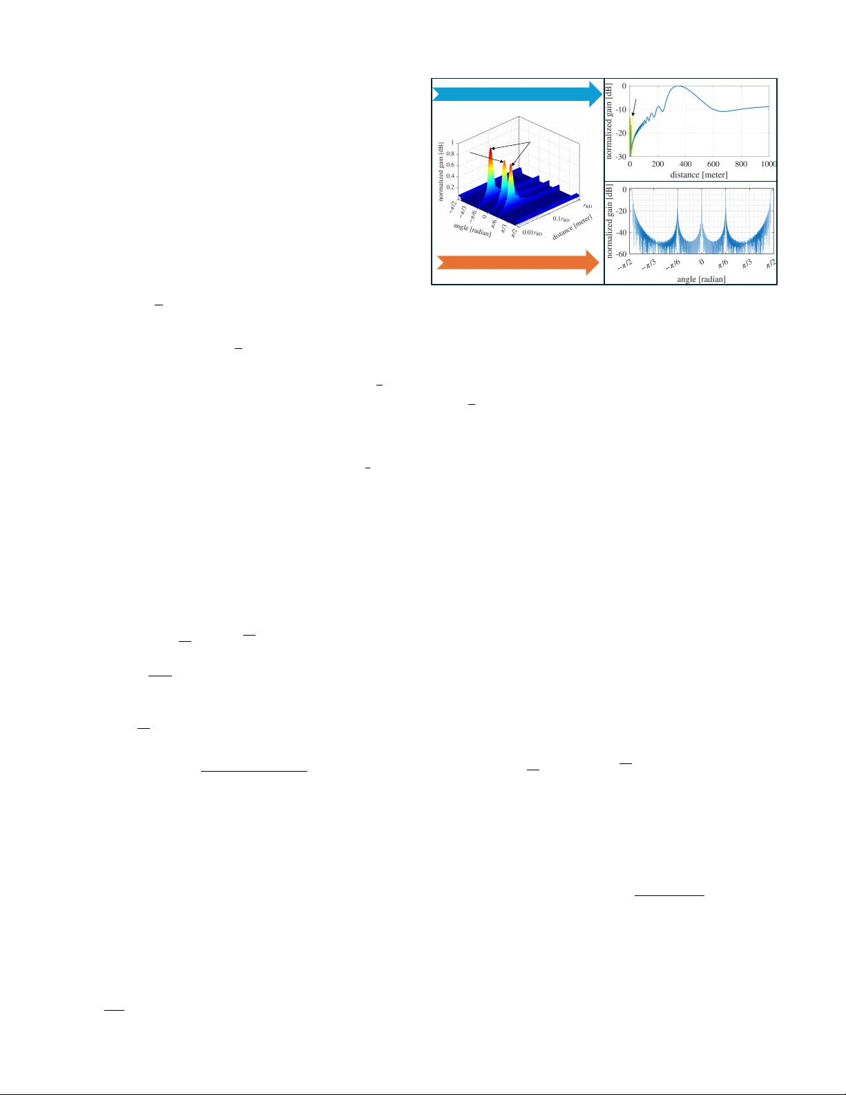
1 Sparse Array Design for Near -Field MU-MIMO: Reconfigurable Array Thinning Approach Ahmed Hussain, Asmaa Abdallah, Member , IEEE , Abdulkadir Celik, Senior Member , IEEE , Emil Bj ¨ ornson, F ellow , IEEE and Ahmed M. Eltawil, Senior Member , IEEE Abstract —Future wir eless networks, deploying thousands of antenna elements, may operate in the radiative near -field (NF), enabling spatial multiplexing across both angle and range domains. Sparse arrays have the potential to achieve comparable performance with fewer antenna elements. Howev er , fixed sparse array designs are generally suboptimal under dynamic user distributions, while movable antenna architectur es rely on mechanically reconfigurable elements, introducing latency and increased hardware complexity . T o address these limitations, we propose a reconfigurable array thinning approach that selectively activates a subset of antennas to form a flexible sparse array design without ph ysical repositioning . W e first analyze grating lobes f or unif orm sparse arrays in the angle and range domains, showing their absence along the range dimension. Based on the analysis, we de velop two particle swarm optimization-based strategies: a grating-lobe-based thinned array (GT A) for grating- lobe suppr ession and a sum-rate-based thinned array (ST A) f or multiuser sum-rate maximization. Simulation results demonstrate that GT A outperf orms con ventional uniform sparse arrays, while ST A achieves perf ormance comparable to movable antennas, thereby offering a practical and efficient array deployment strategy without the associated mechanical complexity . Index T erms —Near -field, sparse arrays, array thinning, particle swarm optimization, MU-MIMO. I . I N T RO D U C T I O N F UTURE wireless networks are expected to deploy increas- ingly large antenna arrays, thereby extending communica- tion into the radiating near-field ( NF ) re gime [ 1 ]. Unlike the far -field ( FF ), where user equipments ( UE s) are multiple xed solely in the angular domain, spherical wa ve propagation in the NF enables finite-depth beamforming that resolves UE s jointly in angle and range. This additional spatial dimension substantially enhances spatial multiplexing gains [ 2 ]. Howe ver , realizing large-aperture arrays with half-wav elength spacing may require thousands of antenna elements, leading to a significant increase in hardware cost, power consumption, and computational complexity . Achieving high spatial multiplexing gain in multi-user multiple-input multiple-output ( MIMO ) systems necessitates strong orthogonality among the UE channel v ectors to suppress inter-user interference. Sparse arrays offer a potential solution, especially in lo w-scattering en vironments, by lev eraging larger Ahmed Hussain, Asmaa Abdallah, and Ahmed M. Eltawil are with Computer, Electrical, and Mathematical Sciences and Engineering (CEMSE) Division, King Abdullah Uni versity of Science and T echnology (KA UST), Thuwal, 23955-6900, KSA. Abdulkadir Celik is with School of Electronics and Computer Science, University of Southampton, SO17 1BJ UK. Emil Bj ¨ ornson is with the School of Electrical Engineering and Computer Science, KTH Royal Institute of T echnology , 100 44 Stockholm, Sweden. The work of E. Bj ¨ ornson was supported by the Grant 2022-04222 from the Swedish Research Council. inter-element spacings to reduce spatial correlation and generate more di verse channels than half-wa velength arrays [ 3 ]. Ne ver - theless, uniform sparse arrays suffer from grating lobes, which cause strong interference by illuminating unintended directions. T o address this limitation, non-uniform array geometries, such as coprime arrays [ 4 ] and array-position optimization techniques [ 5 ]–[ 7 ], have been in vestigated. More recently , mov able antenna (MA) architectures hav e been proposed, wherein antenna elements can be physically reconfigured to match the instantaneous user distribution and enhance channel orthogonality [ 8 ], [ 9 ]. Despite their potential, MA- based designs rely on physically reconfigurable hardware and real-time repositioning, which introduce reliability concerns, latency overheads, and considerable system-le vel complexity . A key limitation of existing sparse array solutions is that they are either static, optimized for a specific user distrib ution and therefore suboptimal under different channel conditions, or mechanical, as in MA architectures that require continu- ous physical movement and high-precision hardware. Both approaches are thus challenging to implement in practical NF multi-user MIMO deployments. T o address these challenges, we propose a reconfigurable array thinning framework in which the full dense array remains physically fixed, but only a selected subset of antennas is activ ated to meet a desired performance objective. That is, rather than redesigning the array geometry or moving antennas, the system forms an effecti ve sparse aperture by selectiv ely switching elements on or off. Array thinning is a well- established technique in radar [ 10 ], where thinned arrays use fe wer radiating elements than a fully populated aperture. Although only a subset of elements is used, the mainlobe beamwidth is preserved due to the unchanged aperture size, while the array gain is reduced proportionally with the number of acti ve elements. The primary benefit is comparable spatial resolution to the full array and acceptable sidelobe levels, while enabling energy-ef ficient operation, reduced hardware complexity , and graceful de gradation. Accordingly , this paper extends the array-thinning concept to NF multi-user communication, enabling the design of dynamic, low-comple xity sparse arrays. W e address three fundamental research questions: First, although it is well kno wn that exceeding half a wa velength yields grating lobes in the angular domain, it remains unclear whether similar phenomena also arise in the range domain. Second, we examine the achie vable multiuser sum-rate when a thinned array is pre-optimized for grating-lobe suppression, and assess the performance gain compared to uniform sparse arrays. Third, we in vestigate ho w 2 to design dynamic thinned arrays that maximize the multiuser sum-rate. T o address these questions, we first inv estigate grating lobes in the NF across both the angle and range domains. Grating lobes arise from the periodicity of the array factor , and understanding this phenomenon is critical for sparse array design. Building on the insights drawn from the analysis of grating lobes, we propose two types of sparse array designs using a particle swarm optimization ( PSO )-based optimization framew ork. The first design, termed as grating-lobe–based thinned array ( GT A ), aims to suppress grating lobes in the NF . The second design, sum-rate–based thinned array ( ST A ), is explicitly optimized to maximize the multiuser sum-rate. W e benchmark the proposed designs against other sparse arrays, including sparse uniform linear array ( SULA ), pre-optimized thinned array ( PT A ), and mov eable uniform linear array ( MULA ). Simulation results sho w that the ST A outperforms other sparse arrays while achie ving performance comparable to that of the MULA . The GT A matches the performance of the PT A , highlighting that grating-lobe–aware optimization ef fec- tiv ely preserves aperture gain while suppressing interference arising due to grating lobes. I I . S Y S T E M M O D E L W e consider a base station ( BS ) equipped with a full uniform linear array ( FULA ) of N antennas with inter -element spacing d = λ 2 , resulting in an aperture length D = ( N − 1) λ 2 . During operation, the BS acti vates only N T antennas, forming a thinned array characterized by the thinning ratio TR = N T N . In a do wnlink free-space line-of-sight ( LoS ) scenario, the BS simultaneously serves K single-antenna UE s, where each data symbol s k is precoded using the beamforming vector w k ∈ C N and transmitted from the BS . The received signal at the k th UE is e xpressed as y k = w H k h k s k + K X j =1 , j = k w H k h j s j + z k , (1) where z k represents additiv e circularly symmetric complex Gaussian noise with variance σ 2 . The channel vector h k ∈ C N between the BS and the k th UE, is gi ven by h k = p β k e − j 2 π λ r k b ⊙ a ( θ k , r k ) , β k = λ 2 (4 π ) 2 r 2 k , (2) where ⊙ denotes the element-wise (Hadamard) product. The coefficient β k captures the path loss, and a ( θ k , r k ) ∈ C N is the NF array response vector corresponding to azimuth angle θ k and range r k . The vector b ∈ { 0 , 1 } N represents the binary thinning weights. An entry b n = 1 indicates that the n th antenna element is activ e, whereas b n = 0 denotes a deactiv ated (thinned) element. In practice, this can be implemented using a dynamic sub-array architecture, in which an RF switch network allows each antenna element to be connected to any radio frequency ( RF ) chain, while inactive elements are terminated to ground. A more po wer-ef ficient alternativ e is a fixed sub- array-based architecture, where each RF chain is restricted to a predefined subset of antenna elements through a switch network. These architectures in volv e a fundamental trade-of f between spectral ef ficiency and po wer efficienc y . A detailed analysis of this trade-off is left for future work. The normalized NF array response vector for the n th antenna, is approximated as [ 11 ] a n ( θ , r ) ≈ 1 √ N e − j 2 π λ { nd sin( θ ) − 1 2 r n 2 d 2 cos 2 ( θ ) } , (3) which is v alid when the UE range exceeds twice the aperture length, i.e., r > 2 D . T o suppress interference in ( 1 ) , we employ a re gularized zero-forcing precoder . The resulting achiev able sum-rate is R sum = K X k =1 log 2 (1 + Γ k ) , (4) where Γ k denotes the signal-to-interference-plus-noise ratio of the k th UE and is gi ven by , Γ k = w H k h k 2 σ 2 + P K j =1 ,j = k w H j h k 2 . (5) For a giv en UE distribution, the sum-rate in ( 4 ) can be optimized by adjusting antenna positions. Howe ver , real-time repositioning incurs high comple xity , cost, and latenc y , as the optimization must be performed whenev er the geometrical parameters of the channel change. T o overcome this, we propose an array thinning strate gy that activ ates only a subset of antennas to achieve performance comparable to the MULA . W e formulate the antenna-activation task as an optimization ov er the activ ation vector b = [ b 1 , . . . , b N ] T . Let f ( b ) denote a generic objective function (e.g., sum-rate). The antenna- selection problem is e xpressed as max b f ( b ) s.t. N X n =1 b n = N T , (6) The constraint P N n =1 b n = N T enforces the thinning ratio, ensuring that exactly N T antennas remain active. While the ov erarching goal remains sum-rate maximization, we employ two alternati ve objecti ve functions f ( b ) which are detailed in Section IV . I I I . G R A T I N G L O B E S I N T H E N E A R - FI E L D Grating lobes introduce undesired interference that can sig- nificantly de grade the multiuser sum-rate. In this section, we analyze the SULA to in vestigate the occurrence of grating lobes in both the angular and range dimensions. A. Grating Lobes in the Angle Domain Consider an NF beam focused at the location ( θ 0 , r 0 ) . The corresponding beam pattern in the angle domain is obtained as G ( θ ) = a H ( θ 0 , r 0 ) a ( θ , r ) 2 = 1 N N − 1 X n =0 e j 2 π λ nd (sin θ − sin θ 0 ) e − j 2 π λ n 2 d 2 2 cos 2 θ r − cos 2 θ 0 r 0 2 ( a ) ≈ 1 N N − 1 X n =0 e j 2 π λ nd (sin θ − sin θ 0 ) 2 , (7) where approximation ( a ) follows from the distance-ring condition cos 2 ( θ ) r = cos 2 ( θ 0 ) r 0 [ 12 ]. This condition defines a set of range–angle pairs along which the beamwidth remains nearly constant. The simplified expression in ( 7 ) represents the array factor in the angle domain. W e present Property 1 to re view grating lobes in the angle domain and then use it to analyze grating lobes in the range domain. 3 Property 1 (P eriodicity Condition of the Array Factor) . Consider the discrete sequence e j ϕ n ( x ) , where x ∈ { θ , r } and ϕ n ( x ) denotes the phase contribution of the n th antenna element. The sequence e j ϕ n ( x ) is periodic if and only if there exists a constant increment ∆ x such that [ 13 ] ϕ n ( x ) − ϕ n ( x 0 ) = 2 π q, q ∈ Z , (8) where x 0 denotes the focused angle/range, and x = x 0 + ∆ x is the observ ation angle/range at which the presence of a grating lobe is e valuated. Applying ( 8 ) to the array factor e xpression in ( 7 ) , the grating lobes occur when the phase shift between adjacent elements equals an inte ger multiple of 2 π [ 13 ] 2 π d λ (sin θ − sin θ 0 ) = 2 π q, q ∈ Z . (9) Solving for θ yields the follo wing grating lobe condition: sin θ q = sin θ 0 + q λ d , q = ± 1 , ± 2 , . . . (10) Grating lobes appear at angles θ q when the mainlobe is focused at θ 0 ∈ [ − 90 ◦ , 90 ◦ ] , provided that | sin θ q | = | sin θ 0 + q λ d | ≤ 1 . For a uniform linear array ( ULA ), the visible angular region is gi ven by θ ∈ [ − 90 ◦ , 90 ◦ ] , so no grating lobes occur within this region when d ≤ λ/ 2 . In contrast, for d > λ/ 2 , additional lobes appear at angular locations determined by ( 10 ) . F or example, when d = 2 λ and θ 0 = 0 ◦ , ( 10 ) reduces to sin θ q = q 2 , which satisfies | sin θ q | ≤ 1 for q ∈ {− 1 , 1 } . The corresponding grating lobe angles are θ q ∈ {− 30 ◦ , 30 ◦ } . B. Absence of Grating Lobes in the Range Domain The beam pattern in the range domain is obtained as the inner product of NF array response vectors gi ven in ( 3 ) , pointing to the same angle θ but different distances r and r 0 [ 11 ] G ( θ , r ) = a H ( θ , r 0 ) a ( θ , r ) 2 , (11) (a) = 1 N N − 1 X n =0 e − j 2 π λ n 2 d 2 cos 2 ( θ ) r eff 2 , (12) where r eff = r − r 0 2 rr 0 in (a). T o assess the possibility of grating lobes in the range domain, the phase in ( 12 ) must satisfy the periodicity condition in ( 8 ): 2 π λ d 2 cos 2 ( θ ) r eff = 2 π q, q ∈ Z , (13) Solving for r yields the follo wing expression: r q = r 0 d 2 cos 2 ( θ ) d 2 cos 2 ( θ ) + 2 q r 0 λ . (14) Howe ver , unlik e the angular domain, where the phase varies linearly with element index n , the phase in ( 12 ) varies quadratically . As a result, at the distances r q giv en by ( 14 ) , the individual element phases do not re-align coherently across the array , and the summation over n does not produce a secondary mainlobe; instead, only small ripples are formed. Furthermore, the resulting r q values are either negati ve (for q < 0 ) or extremely small (for q > 1 ), rendering them physically impractical. Therefore, unlike the angular domain, grating lobes do not appear along the range dimension. T o ex emplify this with a numerical example, we consider a 256 element SULA with inter-element spacing d = 2 λ and an NF beam focused at ( θ 0 = 0 ◦ , r 0 = r RD / 30 = 346 m) , where r RD = 2 D 2 λ denotes the Rayleigh distance. As sho wn in Fig. 1 , we plot the resulting two-dimensional ( 2D ) beam pattern along Grating lobes exist along the angle domain Absence of grating lobes i n the range domain Mainlobe G rating lobe G rating lobe G rating lobe Mainlobe ripples Fig. 1: Beam pattern in angle and range domain: grating lobes appear only in the angular domain. Here we set f c = 15 GHz , N = 256 , d = 2 λ , r 0 = 346 m and r RD = 10 . 3 km . with the corresponding one-dimensional ( 1D ) cuts in angle and range. In the 2D plot, two additional grating lobes emerge at θ = ± π 6 , consistent with the angular positions predicted in the last subsection. In contrast, the range-domain response exhibits no grating lobes. This distinction is further clarified by the 1D angular and range patterns, which highlight the presence of grating lobes solely in the angular domain. Furthermore, small ripples are observed at short ranges in the 1D range-domain response. Specifically , the dominant ripple attains a lev el of − 13 dB at a distance of 0 . 01 m . I V . P RO P O S E D O P T I M I Z A T I O N M E T H O D S In this section, we explain the two proposed array-thinning strategies for optimizing the sum-rate in ( 4 ) . The first method, GT A , suppresses grating lobes, while the second method, ST A , directly maximizes the multiuser sum-rate. A. PSO-based Array Thinning for Grating-Lobe Suppr ession Grating lobes can be mitigated by disrupting the periodic structure of the SULA . Based on the results of Section III , we need to suppress grating lobes only in the angle domain. W e consider the weighted angle-domain beam pattern of a ULA with N antennas, giv en by G ( b , θ ) = 1 N N − 1 X n =0 b n ⊙ e j 2 π λ nd (sin θ − sin θ 0 ) 2 , (15) The thinning problem aims to determine an optimal binary vector b that minimizes the peak sidelobe level ( PSLL ) within a specified angular cov erage region Θ cov . Since the grating- lobe behavior varies with the angle θ 0 , the PSLL is defined as a function of θ 0 as PSLL( b , θ 0 ) = 10 log 10 max θ ∈S G ( b , θ ) G ( b , θ 0 ) , (16) where S denotes the sidelobe region e xcluding the mainlobe around θ 0 . As the steering angle θ 0 increases, additional grating lobes may appear . For a given antenna spacing d , more grating lobes appear as the angle is steered towards the endfire direction. Hence, we aim to design a thinning pattern that minimizes the PSLL ov er the maximum steering angle within the coverage interv al Θ cov . Accordingly , the optimization problem ( 6 ) , where 4 f ( b ) = PSLL( b , θ 0 ) , is formulated as min b max θ 0 ∈ Θ cov PSLL( b , θ 0 ) , (17) s.t. PSLL( b , θ 0 ) ≤ τ PSLL , (18) N X n =1 b n = N T , (19) b n = 1 , n ∈ F , (20) where τ PSLL denotes the maximum allow able sidelobe le vel. The constraint in ( 19 ) enforces a fixed number of active antennas, while ( 20 ) ensures that a predefined set F of mandatory activ e elements (e.g., the two edge elements) is always preserved to maintain the maximum aperture. A direct binary optimization over the thinning vector is computationally intractable due to the combinatorial search space. T o address this, we le verage PSO that optimizes the objective function by iteratively ev aluating P candidate solutions. In PSO , each particle p represents a potential solution. More specifically , we adopt a PSO -based continuous relaxation, where each particle represents a continuous priority vector x ( p ) ∈ [0 , 1] N v . Here, N v = N − |F | denotes the number of v ariable (non-fixed) antenna positions. This vector is subsequently mapped to the binary thinning vector b ( p ) . The complete procedure is summarized in Algorithm 1 . The initialization (lines 3–5) assigns each particle a random position x ( p ) (0) and velocity v ( p ) (0) , constructs the corresponding binary vector b ( p ) (0) , and e valuates the initial cost f ( p ) (0) = f ( b ( p ) (0)) = PSLL( b ( p ) (0) , θ 0 ) . Each particle stores its personal best P ( p ) best and the globally best particle determines G best . At iteration t , the v elocity of the particle p is updated (line 8) according to v ( p ) ( t +1) = ω v ( p ) ( t ) + c 1 u 1 P ( p ) best − x ( p ) ( t ) + c 2 u 2 G best − x ( p ) ( t ) , (21) where ω is the inertia weight, c 1 and c 2 are acceleration coefficients, and u 1 , u 2 ∼ U (0 , 1) are random scalars. The updated velocity yields a new position (line 9): x ( p ) ( t +1) = x ( p ) ( t ) + v ( p ) ( t +1) . (22) The entries of x ( p ) ( t +1) are clipped to the interval [0 , 1] (line 10). In line 11, a new thinning vector b ( p ) ( t +1) is constructed by activ ating the antenna indices corresponding to the T op N T −|F | entries of x ( p ) ( t +1) and appending the fixed set F . The corresponding objectiv e function f ( p ) ( t +1) is e valuated using ( 16 ) . Each particle updates its personal best P ( p ) best whenev er f ( p ) ( t +1) improv es upon its pre vious v alue, and the global best G best is replaced whenev er a particle attains the lo west cost across the swarm. This process repeats for n PSO iterations, after which the optimal thinning vector b opt is obtained by mapping G best to its binary representation. B. PSO-based Array Thinning for Sum-Rate Maximization In this subsection, we explain the ST A to maximize the achiev able sum-rate in ( 4 ) . W e assume that range and angle information of the UE s is kno wn at the BS . For K UE s with θ = [ θ 1 , . . . , θ K ] and ranges r = [ r 1 , . . . , r K ] , we construct the channel matrix H ∈ C N × K based on ( 2 ) . Similar to the structure of the grating-lobe problem, we enforce a fix ed Algorithm 1: PSO for Array Thinning 1 Input: Number of particles P , iterations n PSO , variable indices N v , fixed set F , acti ve antennas N T , PSO parameters ( ω , c 1 , c 2 ) 2 Output: Optimal thinning vector b opt 3 Initialization: x ( p ) (0) ∈ [0 , 1] N v , v ( p ) (0) ∈ R N v , 4 b ( p ) (0) = T op N T −|F | ( x ( p ) (0)) ∪ F , f ( p ) (0) = f ( b ( p ) (0)) , 5 P ( p ) best = x ( p ) (0) , G best = x ( p ⋆ ) (0) , p ⋆ = arg min p f ( p ) (0) 6 for t = 0 to n PSO − 1 do 7 for p = 1 to P do 8 v ( p ) ( t +1) ← // Refer Eq. ( 21 ) 9 x ( p ) ( t +1) ← // Refer Eq. ( 22 ) 10 x ( p ) ( t +1) ← min(max( x ( p ) ( t +1) , 0) , 1) 11 b ( p ) ( t +1) ← T op N T −|F | ( x ( p ) ( t +1)) ∪ F 12 f ( p ) ( t +1) = f ( b ( p ) ( t +1)) // Refer Eq. ( 16 ) 13 if f ( p ) ( t +1) < f ( P ( p ) best ) then 14 P ( p ) best ← x ( p ) ( t +1) 15 end 16 if f ( p ) ( t +1) < f ( b ( G best )) then 17 G best ← x ( p ) ( t +1) 18 end 19 end 20 end 21 b opt = T op N T −|F | ( G best ) ∪ F number of activ e N T antennas and a set F of mandatory activ e indices. The optimization problem ( 6 ) is reformulated as sum- rate maximization problem, where f ( b ) = R sum ( b ) , and is giv en by max b R sum ( b ) , (23) s.t. N X n =1 b n = N T , b n = 1 n ∈ F . (24) The optimization problem in ( 23 ) is combinatorial and NP- hard. Therefore, we adopt the same continuous-relaxation PSO framew ork described in the previous subsection. Each particle p maintains a continuous priority vector x ( p ) ∈ [0 , 1] N v , where N v = N − |F | denotes the number of v ariable antenna positions. A binary thinning vector b ( p ) is obtained by activ ating all fixed indices and selecting ( N T − |F | ) entries with the largest values in x ( p ) . The main distinction from the grating-lobe suppression formulation lies in the objective: the cost function is no w the sum-rate ( f ( b ) = R sum ( b ) ), whereas all PSO update rules remain unchanged. In particular , in line 10 of Algorithm 1 , the cost is computed using the sum-rate expression in ( 4 ). V . S I M U L A T I O N R E S U LT S W e e valuate the performance of the proposed GT A and ST A designs by comparing them against se veral benchmark array configurations. In our setup, the BS employs a FULA with N = 320 antennas, while the thinned configurations activ ate only N T = 32 antennas, yielding a thinning ratio of TR = 1 10 . The carrier frequenc y is 30 GHz and signal-to-noise ratio ( SNR ) is set to 20 dB . The follo wing benchmark arrays are considered: • FULA : A con ventional ULA with N = 320 antennas and spacing d = λ 2 , serving as an upper bound. • MULA : A movable ULA with N = 32 antennas where antenna positions are optimized within [ − 80 λ, 80 λ ] using PSO for each channel realization. • PT A : A thinned array with N T = 32 activ e antennas 5 number of users 1 2 3 4 5 su m-rat e [bp s/Hz] 10 15 20 25 30 FULA SULA Fig. 2: Sum-rate for SULA when UE s are distributed only along the range. sum-r ate [bp s/Hz] 0 50 100 150 200 250 CD F 0 0.2 0.4 0.6 0.8 1 FULA ST A MULA GT A PT A SULA HULA Fig. 3: Cumulativ e distribution function of the sum-rate across different sparse arrays. number of user s 10 15 20 25 30 sum -rat e [bps /Hz ] 100 200 300 400 FULA ST A MULA GT A PT A SULA HULA Fig. 4: A verage sum-rate vs. number of users for different sparse arrays. selected using statistical channel state information ( CSI ), following the approach presented in [ 3 ]. • SULA : A sparse ULA with N T = 32 antennas and uniform spacing d = 5 λ , chosen to match the aperture of the FULA. • Half-wav elength unif orm linear array ( HULA ): A compact ULA with N T = 32 antennas and d = λ 2 . Except for the compact HULA , all configurations share the same aperture length to ensure a fair comparison. W e k eep the PSO parameters as gi ven in [ 3 ]. W e begin with a scenario where all UEs are aligned at the same boresight angle θ = 0 ◦ and randomly distrib uted along the range axis, i.e., r ∼ U [2 D = 3 . 18 m , r RD 7 = 72 . 6 m] , where r RD 7 is the maximum beamfocusing distance at boresight [ 11 ]. Fig. 2 compares the sum-rate performance of the FULA and the SULA , with the beamforming gain normalized by the number of antenna elements. The two configurations exhibit nearly identical performance since (i) they share the same physical aperture and (ii) grating lobes do not occur along the range dimension for the SULA . Nevertheless, the SULA exhibits slightly ele vated sidelobe lev els relativ e to the FULA , which accounts for the mar ginal sum-rate degradation. Next, we consider do wnlink transmission to K = 16 UE s, whose polar coordinates are generated according to r ∼ U [2 D = 3 . 18 m , r RD 7 = 72 . 6 m] and θ ∼ U [ − π 3 , π 3 ] . Fig. 3 illustrates the cumulative distribution function ( CDF ) of the achiev able sum-rate for all considered schemes. As expected, the FULA deliv ers the highest performance due to its full aperture and maximum beamforming gain. The proposed ST A achiev es performance comparable to that of the MULA . Moreov er, it attains approximately 75% of the FULA sum-rate while utilizing only 10% of the activ e elements. The GT A attains performance comparable to the PT A , indicating that grating-lobe suppression ef fectiv ely reduces interference and enhances sum-rate. Although GT A remov es grating lobes, its sidelobes remain relatively elev ated due to irregular element spacing and the reduced number of active antennas. The sum- rate of GT A is on average 5% lower than that of the ST A . Ho wever , the GT A is pre-optimized, whereas the ST A requires more frequent updates depending on the channel geometrical parameters. Finally , Fig. 4 sho ws the average sum-rate versus the number of served UE s. The proposed ST A consistently outperforms all sparse baselines. For moderate system loading, i.e., when N T K > 1 , the sum-rate increases approximately linearly and gradually saturates as N T K approaches unity , due to the transition to an interference-limited regime. Furthermore, the proposed ST A achiev es sum-rate performance comparable to the MULA . Importantly , array thinning provides a hardware- efficient solution that reduces implementation complexity and po wer consumption without requiring mechanical repositioning of antenna elements. Moreover , it enables graceful performance degradation, since faulty elements can be deacti vated and the thinned array configuration can be dynamically re-optimized. V I . C O N C L U S I O N This work introduced a dynamic array thinning frame work to optimize multi-user sum-rate in the near field. The proposed ST A achiev es performance comparable to the MULA while av oiding the hardware challenges associated with MULA . Fu- ture work will explore replacing the PSO with a deep learning- based solution to mitigate the computational complexity of the current optimization approach. R E F E R E N C E S [1] A. Hussain, A. Abdallah, A. Celik, and A. M. Eltawil, “Near-field ISA C: Synergy of dual-purpose codebooks and space-time adaptive processing, ” IEEE W ireless Communs. , vol. 32, no. 4, pp. 64–70, 2025. [2] A. Abdallah, A. Hussain, A. Celik, and A. M. Eltawil, “Exploring frontiers of polar-domain codebooks for near-field channel estimation and beam training: A comprehensive analysis, case studies, and implications for 6G, ” IEEE Signal Pr ocess. Mag . , v ol. 42, no. 1, pp. 45–59, 2025. [3] A. Irshad, A. Kosasih, V . Petrov , and E. Bj ¨ ornson, “Pre-optimized irregular arrays versus mo vable antennas in multi-user MIMO systems, ” IEEE W ireless Commun. Lett. , vol. 14, no. 8, pp. 2656–2660, 2025. [4] C. Zhou, C. Y ou, H. Zhang, L. Chen, and S. Shi, “Sparse array enabled near-field communications: Beam pattern analysis and hybrid beamforming design, ” arXiv pr eprint arXiv:2401.05690 , 2024. [5] K. Chen, C. Qi, G. Y . Li, and O. A. Dobre, “Near-field multiuser communications based on sparse arrays, ” IEEE J. Sel. T opics Signal Pr ocess. , v ol. 18, no. 4, pp. 619–632, 2024. [6] Z. W ang, H. Xu, G. Zhang, X. Huang, and X. He, “Sparse-array-enabled wideband beamforming for near-field multiuser communications, ” IEEE Internet Things J . , v ol. 12, no. 22, pp. 48 428–48 440, 2025. [7] E. Bj ¨ ornson, A. Irshad, ¨ O. T . Demir , G. T . F . de Abreu, A. K osasih, and V . Petrov , “From antenna abundance to antenna intelligence in 6G gigantic MIMO systems, ” arXiv pr eprint arXiv:2601.08326 , 2026. [8] L. Zhu, W . Ma, and R. Zhang, “Movable antennas for wireless communication: Opportunities and challenges, ” IEEE Commun. Mag. , vol. 62, no. 6, pp. 114–120, 2024. [9] L. Zhu, W . Ma, W . Mei, Y . Zeng, Q. W u, B. Ning, Z. Xiao, X. Shao, J. Zhang, and R. Zhang, “ A tutorial on movable antennas for wireless networks, ” IEEE Commun. Surv . Tutor . , 2025. [10] R. Haupt, “Thinned arrays using genetic algorithms, ” IEEE T rans. Antennas Propa g. , vol. 42, no. 7, pp. 993–999, 1994. [11] A. Hussain, A. Abdallah, and A. M. Eltawil, “Redefining polar boundaries for near-field channel estimation for ultra-massive MIMO antenna array , ” IEEE T rans. Wir eless Communs. , v ol. 24, no. 10, pp. 8193–8207, 2025. [12] H. Zhang, C. Y ou, and C. Zhou, “Near-field beam-focusing pattern under discrete phase shifters, ” IEEE T rans. W ireless Commun. , pp. 1–1, 2025. [13] R. C. Hansen, Phased arr ay antennas . John W iley & Sons, 2009.
Original Paper
Loading high-quality paper...
Comments & Academic Discussion
Loading comments...
Leave a Comment