Modeling of Human Body-coupled Electric Field Interference in Unshielded Ultra-Low Field MRI
Portable ultra-low field MRI (ULF-MRI) systems operated in unshielded environments are susceptible to electromagnetic interference (EMI). Subject presence in the imaging region will lead to substantial noise increases, yet the dominant coupling mecha…
Authors: Jiali He, Yamei Dai, Sheng Shen
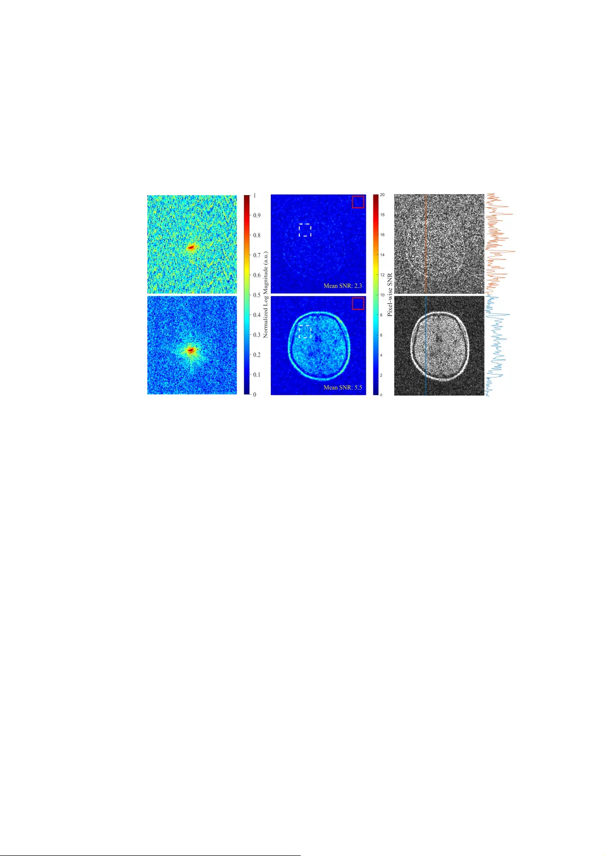
Modeling of Human Body-coupled Electric Field Interference in Unshielded Ultra-Low Field MRI Authors Jiali He, 1 Yamei Dai, 1 Sheng Shen, 2,3 Jiamin Wu, 4 Zheng Xu 1* Affiliations 1. School of Electrical Engineer ing, Chongqing University, Chongqing 400044, China 2. A.A. Martinos Center for Biomedi cal Imaging, Massachusetts General Hospital, Boston, MA, USA. 3. Harvard Medical School, Boston, MA, USA. 4. Shenzhen Academy of Aerospace Technology, Shenzhen 518057, China. *Correspondence to: Zheng Xu, Ph.D., Prof. The school of Electr ical Engineering Chongqing University, Chongqing, China. Email: xuzheng@cqu.edu.cn Copyright Statement: This work has been submitted to the I EEE for possible publicati on. Copyright may be transferred without notice, after which th is version may no longer be accessible. Abstract: Portable ultra-low field MRI (ULF-MRI) syste ms operated in unshielded environments are susceptible to electroma gnetic interferen ce (EM I). Subject presence in the imaging region will lead to substantia l noise increases, yet the dominant coupling mechanism remains insuffic iently charac terized. We develop a lumped-parameter circuit model of the cou pled environmen t-body-receiver system. The model indicates that ambient time-varying electric fields induce a body common-m ode potential, which is converted into differen tial-mode noise through capaci tive imbalance between the head and the receive-coil terminals, y iel ding strong dependence on subject position and geometry. Circuit analysis, si mulations, and controlled expe riments support the model, with predicted imbalance consistent with mea sured noise variations. Gu ided by this mechanism, we implement a capacitive low-impedan ce bypass to clamp the body potential, achieving an approximately 3.5-fo ld SNR improvement on a 50 mT prototype. The proposed model offers a compact circu it-based tool for anal yzing and mitigating human body-coupled electric-field in terference in portable ULF-MRI. Keywords: Capacitive imbalance, Electric-field interference, Human body-coupled, Lumped-parameter circuit model, Ultra-low field MRI. INTRODUCTION Ultra-low-field magnetic resonan ce imaging (ULF-MRI) has attracte d increasing attention in recent years due to its low cost , the absence of electromagn etic shielding requirements, and favorable portability [1]– [1 1]. These characteristics make ULF-MRI particularly promising for bedside diagnosis, emergency medicine, and healthcare delivery in resource-limited o r remote se ttings [12]. However , ULF-MRI systems typically operate under low static magnetic fields (generally below 100 mT) and in non- shielded environments, where they inherently suf fer from both weak intrins ic signal strength and pronounced susceptib ility to external electromag netic interference (EMI). The combined ef fect of these factors consti tutes a primary limitation on the achievable signal-to-noise ratio (SNR) in ULF-MRI [7]. In non-shielded ULF-MRI systems, external EMI couples into the system mainly through conducted, magnetic-field, and electric-field pathways, as shown in Fig. 1 [13]. Conducted interference enters via power or ground lines and can be mitigated by filtering and grounding optimization [14]–[16] . Magnetic-field coupling results from electromagnetic induction, whereby low-fre quency environmental fields induce differential-mode voltages in the receive coil. In addition, ferromagnetic yokes and structural components can change the intern al interference magnetic -field distribution, leading to anisotropic attenuation and, in multichannel systems, channel-dependent SNR imbalance, as analyzed in our previous work [17]. Inte rference radiat i on to t he human body Inte rference radi ati on int o the cavi ty P ow e r S o u r ce I n d u cti ve Co up li ng Ca pa cit iv e Co upl i ng Co nd ucti ve Co up l ing No is e Sou rce Fig. 1. Schematic illustration of EMI coupling pathwa ys in an ultra-low-field MRI system. Fig. 2. Comparison between water phantom and brai n imaging results acquired under identical experimental conditions. Electric-field coupling is particularly pr onounced in non-shielded ULF-MRI systems, as shown in Fig 2. Numerous studies have qualitatively reported a substantial noise increase when a subject enters the imaging volume [18]–[20]. The human body is directly exposed to the ambien t electroma gnetic environment and ef fectively acts as a coupling pathway between external EMI and internal system components, allowing external electric-field noise to couple into th e centrally located RF receive coil. From an engineering perspective, existi ng solutions can be grouped into two broad categories. T he first relies on passive sh ieldi ng to isolate the system from environmental EMI, often at the expense of portability and, in some cases, with increased discomfort for claustrophobic patients [21]–[23]. The second comprises active noise cancellation and signal/image-domain processing met hods, such as noise-channel modeling [13], [24]–[27] and AI-based appro aches [3], [9], [28]–[32] (e.g., deep learning). Although these methods can be ef fective, their performance often hinges on the accuracy of the assumed noise model and/or th e availability of representative training data. More generally , EMI mitigation in ULF-MRI remains largely “res ult-oriented,” prioritizing post hoc suppression after interference has en te red the receive chain rather than quantitatively characterizing th e physical coupling pathways by which environmental noise reaches the RF receive coil. In particular , the human body in imaging is typically described only qualit atively as an “antenna ef fect,” and a quantitative environment–body–system coupli ng model that explic itly treats the body as a dominant pathway is still lacking. As a result, in bedside settings, the mechanisms , coupling strength, and dominance conditions under which e nvironmental RF noise couples into the receive co il remain insuff iciently understood. Establishing such a model is therefore essential for developi ng physically interpretable, real-time mitigation strategies that avoid bulky shielding. Motivated by these considera tions, this work focuses on electric- field coupling and proposes an environment–human body–receiv er modeling framework for ULF-MRI, complementing previously re ported magnetic-field coupling models [17]. A multi-node lumped-element equivalent circuit mode l tailored for ULF-MRI is introduced to describe the transmission pa thways of electric-field-rela ted EMI and to analy ze key sensitive parameters go verning coupling strength. Based o n this model, interven tion and suppression strategies targeting capacitive coupling pathways are further discussed, with the aim of reducing elec tric-field-induced noi se in the receive chain. The proposed framework provides a reusable modeling appr oach and theoretical basis for analyzing and mitigating EMI in portable ULF-MRI systems. METHODS A. Quasi-Static Capacitive Coupling In unshielded bedside environments, the su rrounding power infrastructure, lighting, and electronic devices act as distributed sources of time-varying elec tric fields. When a subject is placed in the imaging region, the body can be regarded as a conductive object covered by a thin insulating layer , so extern al electric fields i nduce redistribution of surface char ges and a fluctuating body poten tial. This potential drives displacemen t currents through unavoidable parasitic capac itances among the body , the RF receive coil, and nearby metallic st ructures, providing a primary pathway for elec tric-field interference to enter the receive chain [33]–[36]. At the ULF-MRI operating frequency(2.23MHz) considered here, the in teraction is dominated by quasi-static electric-field coupling; therefore, th e environment–body–coil interaction can be modeled using an equivalent capacitive ne twork in the subsequent noise-channel formulation [37]. B. Equivalent-Circuit Modeling of th e Brain–Receive-Coil Interaction The preceding analysis shows that, in typica l bedside scenarios, the electromagnetic environment around the human body is domin ated by the reactive near field, where low-frequency electric-field coupling is gove rned by quasi-s tatic char ge distributions. Under these conditions, body–coil interactions can be naturally described using a capacitive coupling framework [33]–[37]. Ac cordingly , this section outlines the modeling assumptions for brain–coil electr ic-field coupling and develops a lumped- element capacitive circuit model to anal yze the associated noise mechanism. In the representative head ULF-MRI configur ation (Fig. 3), saddle or solenoidal rec eive coils surround the head; taking the solenoidal coil as an exam ple, anatomical constraints lead to partial axial loading of the coil, with remaining s ections exposed to air or low- permittivity media. This part ial-filling effect produces pronounced axial nonuniformity in the electromagnetic environment, which constitutes a key physical feature of human- mediated electric-fie ld coupling. T o capture this spatially nonuniform coupling behavior , Fig. 3(b) presents a distributed- parameter model of the solenoidal coil and br ain based on the partia l element equivalent circuit (PEEC) method [38]. In this representa tion, the coil consists of n turns, each subdivided into m discrete elements connected in series. The j -th element of t he i -th turn is characterized by its intrinsic di stributed impedance, including resistance R ij and inductance L ij , as well as a coupling capacitance C ij between the coil element and th e brain. Owing to spatially vary ing geometric separation between dif ferent coil segments and the head, these coupling capacitances are not uniform but vary systematically along the coil axis. For the discrete node indexed by i * m + j , the corresponding coupling capacitance C ij can be defined by a line inte gral along the conductor path. () () () n ij n l sw Cx d s ds (1) where w denotes the ef fectiv e conductor width, d ( s ) represents the lo cal separatio n between the conductor and the brain surface, and ε is the ef fective relative permittivity along the integration path. Based on the aforementioned physical partit ioning, the discretized coil nodes can be classified into a proximal loaded region 𝒩 pr ox and a distal unloaded region 𝒩 disk . Due to substantial dif ferences in both dielectr ic properties and ge ometric conditions, the corresponding coupling capacitances in these two regions satisfy the inequality given b Equi valen t circu it C 11 C 12 C 21 C nm L 11 R 11 L 1m R 1m L 21 R 21 L nm R nm C 1m C n1 V h a R L R L (a) R n6 L (n/ 2)1 L (n/2 )2 L (n/2 )3 L (n/ 2)4 L (n/2 )5 L (n/ 2)m R (n/ 2)1 R (n/ 2)2 R (n/ 2)3 R (n/2 )4 R (n/ 2)5 R (n/2 )6 R (n/ 2)m C (n/2 )1 C (n/2 )2 C (n/2 )3 C (n/2 )4 C (n/2 )5 C (n/2 )6 C (n/2 )7 C (n/2 )m L (n/2 )6 L 16 L 11 L 12 L 13 L 14 L 15 L 1m R 11 R 12 R 13 R 14 R 15 R 16 R 1m C 1m C 11 C 12 C 13 C 14 C 15 C 16 C 17 L (n/2 +1)1 L (n/2 +1)2 L (n/2 +1)3 L (n/ 2+1)4 L (n/ 2+1)5 L (n/2 +1)m R (n/ 2+1)1 R (n/2 +1)2 R (n/2 +1)3 R (n/2 +1)4 R (n/ 2+1)5 R (n/ 2+1)6 R (n/ 2+1)m L (n/ 2+1)6 C (n/2 +1)m C (n/2 +1)1 C (n/2 +1)2 C (n/2 +1)3 C (n/ 2+1)4 C (n/2 +1)5 C (n/ 2+1)6 C (n/ 2+1)7 L n6 L n1 L n2 L n3 L n4 L n5 L nm R n1 R n2 R n3 R n4 R n5 R nm C nm C n1 C n2 C n3 C n4 C n5 C n6 C n7 Saddle coil Head L n3 Head Solenoid c oi l 3D Model PEEC C 11 C 12 C 13 C 14 C 1m C 15 C 16 R 1m R 11 R 12 R 13 R 14 R 15 R 16 L 1m L 11 L 12 L 13 L 14 L 15 L 16 head C n1 C n2 C n3 C n4 C nm C n5 C n6 R nm R n1 R n2 R n3 R n4 R n5 R n6 L nm L n1 L n2 L n4 L n5 L n6 head (b) 3D Model PEEC (c) C 22 L 2m R 2m C 2m C 31 x y x z Fig. 3. Distributed-parameter models of the brain–c oil system. (a) Saddle coil with the brain. (b) Solenoidal coil with the brain. (c) Corresponding e quivalent circuit model. in (2). , p rox dist k l kl C C (2) This inequality captures the fundamental asymmetry of the brain–coil coupling and forms the physical basis for the subsequent development of the equivalent model. While the distributed formula tion captures local brain–co il coupling, this study focuses on the equivalent noise behavior at th e coil terminals induced by the body-related common-mode potential rather than the inte rnal voltage distribution. Accordingly , the distributed coupling network is reduced to a two-port lumped cap acitive model. The Appendix rigorously derives this equivalen ce, showing that the ef fective terminal capacitances depend on both coil geometry and the spatially weighted distribution of coupling capacitances. C. System-Level Equivalent-Circuit M odel of the Environment–Body–Receive Chain Based on the preceding analysis, dif ferential- mode interference arises primarily fro m nonuniform brain loading along the receive coil. V ariations in the filling factor—axial for solenoidal coils and transverse for saddle coils—produce unequal ef fective coupling capacitances at the coil termina ls, enabling conversion of c ommon-mode noise into differential-mode interference. T o captu re the resulting interactions among the environment, the human body , and the receive coil, a unified system-level equivalent circuit model is th erefore required. Fig. 4(b) shows an integrated capacitive coupling model of the environment–body–coil system abstracted from the bedside scenar io in Fig. 4(a). Environmental EMI is modeled as an equivalent source V E coupled to the body through C EH . 𝑉 𝐸 lumps the net contribution of ambient, spat ially distributed low-frequency E -field sources (e.g., power lines and lighting systems) into an ef fective excitation. Because the body is not an ideal ground, the finite body-to-ground imp edance—set by C Hg and the effective body–bed–ground capacitances C Hn and C ng —establishes a body common-mode potential V h . Nodes a and b represent the two terminals of the coil, which consists of an inductance L coil and a resistance R coil in series. The coil is connected to the downstream preamplifier (with input impedance Z L ) via a π -type matching network and a coaxial cable. The ef fective brain-to-terminal coupling capacitances C Ha and C Hb form the main paths that convert V h into dif ferential-mode interfe rence at the coil ports, while C ag and C bg account for terminal-to-gro und parasi tic capacitances; their equivalent representations are deta iled in the appendix. Equ ipme nt Noi se sour ce: V E F-GND ( floor ) C EH C Ha C Hb Hu man b ody C ag C bg b a Body pot ent i al: V h RF coil C Hn Bed Vn L co il R coil C t C m2 C m1 Z L Rec ei ving Ci rcu it C ng C Hg Ma tc hi ng N et w or k d c (a) (b ) Fig. 4. (a) Imaging Scenario of the Non-Shielded ULF-MRI Platform. (b) Equivalent circuit model of human-mediated electri c-field interference coupling. The common-mode body potential V h acts as the effective driv ing source of the interference system, with its amplitude determined by the noise-source voltage V E through the associated voltage-divider network. Because the weak body-to-coil coupling capacitances (on the order of pi cofarads) exhibit very high impedances— significantly larger than the impedance of the body-to-gr ound return path—the loading effect of the receive coil can be neglec ted. Under this assumption, the body potential V h can be approximated as: EH hE EH HG C VV CC (3) W e first define the admittances of the i ndividual circuit branch es, starting with the admittance of the noise-injection pa th: Yj C Yj C EH EH H GH G , (4) Here, C HG denotes the total effective body-to-g round capacitance, in corporating both the direct body-to -ground capacitance C Hg and the capacitance associated with the bed - mediated grounding path. Hn ng Hn ng HG Hg C C C C CC (5) The coupling admittances between the human body and coil terminals a and b are defined as Y Ha = j ω C Ha and Y Hb = j ω C Hb , respectively . The parasitic admittan ces from the coil mechanical enclosur e to ground at terminals a and b are denoted by Y ag = j ω C ag and Y bg = j ω C bg . The coil resonant circuit, consisting of L coil , R coil , and the tuning capacito r C t , together with the matching network branch C m , is connected in parallel across terminals a and b . The resulting total shunt mutu al admittance is defined as Y X , given by: 1 2 m Xt coil coil m L jC Yj C Rj L j C Z (6) The third term represents the admittance of the series branch formed by the matching capacitor C m and the load Z L , arising from the floating condition of the output nodes c and d . According to Kirchhoff ’ s current law (KCL), the following relations can be written for nodes a and b : () () 0 () () 0 ah H a ab X a a g bh H b ba X b b g VV Y VV Y V Y VV Y VV Y V Y (7) Rearranging the above equations yields the standard linear matrix form AV = I : aa X a Ha h Xb b b H b YY V Y V YY V Y (8) Here, the diagonal elements Y aa = Y X + Y ag + Y Ha and Y bb = Y X + Y bg + Y Hb represent the self- admittances of the corresponding node s. The analytical solution for 𝑉𝑎𝑏 is obtained as: H ab g H ba g ab h YY YY VV D (9) where: () ( ) ( ) X a g b gH a H b a gH a b gH b D YY Y Y Y Y Y Y Y (10) T o obtain the model with practical engineer ing relevance, two simplifying assumptio ns grounded in physical considerations are introduced. First, owing to the geometric symmetry of the RF coil and its enclosure, the parasitic admittances to ground at the two terminals can be assumed equal, i.e., Y ag = Y bg . Second, the coupling capacitances between the human body and th e coil through air are much sm aller than th e capacitance between the metallic mechanical structure and ground, implying Y g ≫ Y Ha , Y Hb . Under these assumptions, (9) can be simplified to: () 1 2 2[ ] 1 Ha Hb Ha Hb ab h h m Xg tg coil coil m L YY j C C VV V jC YY jC jC Rj L j C Z (1 1) Finally , the input voltage V cd of the downstream circuitry is determined by the voltage- division effect of the matc hing network, corresponding to the detected noise signal: () tota l cd h Ha Hb VZ Vj C C (12) Where, 1 2 2[ ] 1 1 mL m mL tg coil c to oil m L tal Z jC Z jC j CZ jC jC Rj L j C Z (13) Equation (12) indicates that human-mediated electric-field inte rference coupling is primarily governed by thr ee factors: (i) Source—the common-mode body potential V h , which depends on the strength of external interference and the associated voltage- divider network; (ii) Conversion mechanism—the imbalance in coupling capacitances between the brain and the two coil groups, quantified as Δ C = C Ha − C Hb ; and (iii) Gain factor—the total impedance of the receive chain, including the matching network and the downstream circuitry . D. Sensitivity Analysis of Noise Voltage Based on the equivalent circu it, (13) shows that the dif f erential-mode noise voltage V cd is governed by three system parameters. Ef fective suppression w ithout compromising imaging performance requires assessing which parameters are practically controllable under physical constraints. First, Δ C q uantifies the imbalan ce of the tw o coupling capacitances and thus the geometric asymmetry of the noi se-transmission path. Although Δ C =0 would ideally cancel dif ferential-mode noise, Δ C is strongly perturbed by subject-specific anatomy and inevitable positionin g variability , making picofarad-level balanc ing impractical and difficult to guarantee through coil geometry alone. Second, Z total sets the transfer gain from coupled noise to termin al voltage. While lowering Z total reduces the noise amplitude, electromagnetic reciprocity link s receive sens itivity to coil Q and loop impedance, so decreasing Z total also reduces MR signal ampl itude and yields little net SNR benefit. W ith geometric balance and loop impeda nce both constrained, suppressing the body common-mode potential V h becomes the primary rema inin g degree of freedom. From the divider relation in (3), V h is determined by the ra tio of the body-to-ground impedance to the environment-to-body coupli ng impedance. Accordingly , we introduce Equ ipm ent C HG Noi se source : V E F-GND ( flo or ) C EH C Ha C Hb Hum a n body C ag C bg b a Body pote ntial: V h RF co il Bed Vn L coil R coi l C t C m2 C m1 Z L Receivi ng Ci rcu it Matc hi ng Netw ork d c Metal Blank et Fig. 5. Equivalent circuit model with an added grounded metallic blanket. a capacitive grounding strategy (Fig. 5) that reshapes the body-to-ground network by placing an insulated conductive layer near the subject, ef fe ctively adding a large shunt capacitance C HG to ground in parallel. Because C HG ≫ C EH , this provides a low- impedance bypass for common-mode currents and clamps the otherwise floating V h toward ground, suppressing differential-mode noise at its physical origin. Importantly , this approach is lar gely i ndependent of the RF receive loop, enabling mitigation of electric-field-coupl ed interference without degradi ng geometric balance or reducing loop impedance. EXPERIMENTS AND RESULTS T o validate the model, three types of simula tions and experiments we re performed. First, capacitive imbalance between the head and tw o receive-coil types wa s investig ated by varying the head–coil relative position and analyzing th e resulting noise changes. Second, the effect of the body-related potential 𝑉 ℎ was evaluated by fixing the head– coil position (thus keeping the coupling-capac itance dif ference constant) while varying the exposed area to modulate 𝑉 ℎ ; aluminum plates of dif fer ent lengths were used to emulate this condition. Third, the effectiven ess of a grounded metallic blanket was assessed by comparing the resulti ng noise levels and image SNR. A. Experimental Setup The experimental platform used in this study was a self-dev eloped, portable, non- shielded 50 mT ULF-MRI scanner , as show n in Fig. 6. T o achieve portability and electromagnetic isolatio n, a ll electronic subsystems, incl uding the gradient power amplifiers, radio-frequency (R F) power amplifier , spectrome ter , and RF switching unit, were enclosed within an alum inum housing and integrated into the magnet frame, with the exception of the preamplifier . Signa l acquisition was performed using an MR solution EVO spectrometer (MR Solutions, UK) with 8 receive channels and 1 trans mit channel. Both the solen oidal and saddle receiv e coils were tuned and impedance- matched to 2.23 MHz. Fig. 6. Portable 50 mT ULF-MRI system. The scanner was deployed inside a building located in an industrial park . During data acquisition, no restrictions we re imposed on the external el ectromagnetic environment. Major sources of interference include d nearby MRI systems, LED lighting infrastructure, and mobile phones. Unless othe rwise specified, all experiments reported in this work were conducted under these c ond itions. All imaging experiments employed a three-dimensional gradient-echo (GRE) sequence, with an acquisition time of approximately 2 minutes per scan. B. Noise Induced by Δ C This section validates the influence of the coupling-capacitan ce dif ference Δ C on common-mode noise conversion predicted by (12). Given the anatomical complexity of the human head and lar ge inter-subject var iability , we do not attempt to extract subject-specific absolute capacitance va lues; instead, we focus on how capacitive imbalance evolves with head–c oil misalignment and how it governs the termin al noise amplitude. 1) Solenoidal coil T o enable trend-oriented analysis with physically grounded simpli fications, the head was represented by a hemisphere–cylinder composite (Fig. 7(b)) that pre serves the main volume while introducing axia l asymmetry re levant to Δ C . For the sole noidal receive coil, the discrete windings were approxi mated by two axially separated continuous conductive rings with id entical ef fective coverage. This approximation is justified by electrostatic homogenization: in the quasi-static regime, frin ge fields bridge inter -turn gaps, rendering tightly w ound solenoids capacitively eq uivalent to a continuous conductor . Ansys Q3D simulations confirm th is equivalence, showing less than a 5% difference in coil-to-ground coupling capaci tance between the tw o models, thereby supporting the ring representation as an ef ficient surrogate fo r coil–head capacitive coupling. Using these simplified models, coil–head c oupling capacitan ces were computed (via a coaxial cylindrical-capacito r approximation) while incrementally translating the head model along the X-axis to emulate varying relative positions. Fig. 7(a) reports the coupling capacitances to the posterior and an terior coil segments and their dif ference Δ C (origin at the coil center , abscissa defined by the displacement of the head apex). A finite Δ C exists even at the nomin ally centered position due to intrinsic head asymmetry . As the head moves in the +X direction, the posterior coup ling decreases first, whereas the anterior coupling remains relative ly high, producing a pronounced rise in Δ C ; once the head moves beyond the ef fective coverage of the an terior segment, the anterior coupling also decreases and Δ C correspondingly drops, yi elding a characteristic increase–decrease profile. Fig. 7(c) shows the measured terminal noise amplitude between nodes a – b , whose peak variation closely tracks Δ C , thereby confirming that capacitive imbalance is the dom inant driver for converting body-rela ted common-mode excitation into dif ferential-mode in terference in this configuration. Inset: Peak regi on (a) (b ) (c) Noise vo ltage(V) x y z Fig. 7. Simulation and experimental validation of noise mechanisms induced by capacitive coupling imbalance. (a) Simulate d coil–brain coupling capacitances ( C Ha , C Hb ) and their difference ( Δ C) as functions of head di splacement along the positive X-axis; (b) simplified geometric model used in simulations, illustrati ng the relative configuration of the solenoidal coil (conductive ring bands) and the head model (hemisphere–cyli nder composite). The extracted noise envelope and peak amplitude reflect the dynamic noise behavior as the head gradually moves out of the coil; (c) experiment ally measured normalized noise amplitude in the solenoidal coil as a function of head position, demonstrating agreement between simulation predictions and measurements. T o corroborate the simulations, experimental measurements were performed with the constructed setup while keeping all other system components unchanged. The subject’ s head was gradually moved out of the sole noidal coil, and Fig. 7(c) shows that the measured normalized noise amplitude ag rees well with the predicted trend. The experimental baseline is slightly higher than the simulated level, likely due to additional contributions (e.g., circuit th ermal noise and envi ronmental magnetic in terference) that are not included in the simpli fied capacitive coupling model. Representative imaging results under differen t head positions are shown in Fig. 8. When the head is centered in the solenoidal coil, the mean SNR within the white boxed region is ~5.5; with an offset head position, th e mean SNR drops to ~2.3, corresponding to a ~2.4× reduction. Consistent with this quantitative metric, the reconstructed images and one-dimensional intensity profiles at match ed anatomical locations exhibit a pronounced noise increase under the offset condition, with partial masking of the MR signal and degraded delin eation of tissue boundaries. K-s p a ce M a g n i t u d e Pix e l-w i s e S N R Map I mag e & Prof il e Of fset C en t ered Fig. 8. Imaging comparison with the head centered and offset relative to the solenoidal coil. From left to right: logarithmic k-space magnitude spectra, pixel-wise SNR maps, and reconstructed images with corresponding one-dimensional intensity profiles. 2) Saddle coil After establishing the capacitive-imbalance noise mechanism for the solenoidal coil, we experimentally validate th e same mechanis m for a sadd le coil. Although the saddle geometry differs, dif ferential-mode inte rference still originates from coupling- capacitance imbalance under a body-relate d common-mode potential; the main difference is that saddle coils are more sens itive to transverse (Y -axis) asymmetry . Therefore, to avoid redundancy , we omit detailed simu lations and verify the predic ted noise behavior directly via measurements. Fig. 9 summarizes the measured noise trends under controlled asymmetry . In Fig. 8(a), varying the head azimuth shows minimum noise when the head is centered, whereas rotation toward either si de progressively breaks symmetry and increases noise. Because head motion is limited within the saddle co il, we further used the subject’ s hands as surrogate loads (Fig. 8(b)). W ith single-ha nd loading, noise is minimized at the coil center and increases as the hand moves towa rd the edge; with symmetric two-hand loading, the noise is markedly reduced. T ogether , these results demonstrate that restoring symmetric lo ading compensates capacitance imbalance and confirms that the coupling-capacitance dif ference is the domin ant driver of noise generation in the saddle-coil configuration. (a) Both Hand s Move to t he rig ht Si ngle Han ds x y x y (b ) Fig. 9. Measured noise variation detected by the saddle coil as a function of object position. (a) Noise amplitude versus head azimuthal deviation (left–right rotation) relative to the saddle coil; (b) symmetry validation using a hand-based surrogate model, comparing noise levels under single-hand displacement and symmetric two-hand placement. C. Noise Induced by V h This section isolates the effect of the body common- mode potential V h on terminal noise , as predicted by (12), while keeping the coupling-capacitance imbalance Δ C unchanged. Because V h increases with stronger coupling to am bient electric fields, we modulate the effective common-mode excita tion by varying the exposed length/area of a conductive object in free space. T o prevent subject motion a nd inter-subject geometry from altering head–coil coupling and Δ C, we replace the subject with an alum inum-plate phantom that behaves as a stable floating conductor and allows repeat able positioning. The plate overlap inside the coil is fixed to maintain constant coil–load co upling (and Δ C ), and only the length extending outside the coil is varied from 50 to 200 cm to change environment coupling and V h . Under this design, the meas ured noise variation is attributed primarily to changes in V h [18]. x y z Fig. 10. Linear increase of terminal noise w ith aluminum-plate exposure length. The exposed portion of a floating conductor in a non-shielded environment behaves like a monopole receiver whose ability to intercept the background electric field increases with length, whic h the proposed circuit model captures primarily as an increase in the common-mode potential V h . As shown in Fig. 10, the noise amplitude measured at the coil termin als increases approximately linearly with the exposure length, consistent with the pr edicted linear dependence on V h . These results support the interpretation that, once Δ C is fixed, variations in environment coupling strength dominate the modulation of system noise, va lidating the common-mode source term in the proposed equivalent model. D. Suppression Strategy Fig. 1 1 summarizes the impact of intr oducing a capacitive grounding blanket on a non- shielded 50 mT ULF-MRI platform. In th e frequency domain (Fi g. 1 1(a), left and middle), the baseline logarithmic k-space ma gnitude spectra exhibi t strong broadband, unstructured background components, indicating substantial common- mode interference from the surrounding environmen t. W ith the grounding blanket applied, this k-space clutter is ma rkedly suppressed, and si gnal ener gy becomes more concentrated, demonstrating effective a ttenuation of interf erence components. These improvements translate directly to imag e-level performanc e. Pixel-wise SNR maps show a pronounced SNR increase across the brain; within the white-boxed region, the mean SNR rises from 5.5 to 19.5 ( ≈ 3.5×). Consistent with this quantitative gain, reconstructed images and matched one-dimensio nal intensity profiles (Fig. 10(a), right) reveal a clear reduction in background fluctuations. Tissue contrast and boundary delineation are improved, while no noticeable loss of fine structural detail is observe d, indicating that the suppression reduces el ectric-field-coupled in terference without sacrificing image resolution. Cent ered / Gro un ded Ma t Cent ered / No M at K- spa ce Mag ni tude Pi xe l-wi s e S N R Map Im age & P rof ile (a) (b ) Fig. 11. Validation of the proposed suppression strategy. (a) Baseline and suppressed imaging: k-space spectra, SNR maps, and reconstructed imag es with intensity profiles, showing reduced background noise and improved SNR.(b) Noise am plitude versus axial head position witho ut and with suppression, demonstrating effective attenuation of position-de pendent interference. T o evaluate robustness to subject-position variability , Fig. 1 1(b) reports the noise amplitude as a function of head position along the axial direction ( x ∈ [ − 100mm,150mm]). W ithout supp ression, noise shows strong position dependence and peaks near the coil center ( x = − 10mm), cons istent with the previously analyze d imbalance-driven trend. W ith the grounding blanket, noise is suppressed across the entire range, with an ov erall reduction exceeding 80% ; although a weak residual position dependence remains, its absolute magnitude is grea tly diminished, demonstrating improved stability un der practical bedside conditions. DISCUSSION This study investigated the physical origin of human body- couple noise and corresponding suppression strate gies in portable ultra-low- field MRI systems operating in non-shielded environments. Experiments confirm that the human body provides a significant coupling pathway that elevates system noise and degrades image quality via electric-field coupling. The discussion fo cuses on (i) the dominant physical factors governing noise increments, (ii) a comparis on of front-end suppression strategies for electric-field-coupled noise, and (iii) co il-geometry-dependent noise sensitivity . A. Dominant Contribution of Coupling-Capacitance Imbalance to Noise In the head-displacement experiment (Fig. 7(c)), two ef fects vary concurrently: the brain–coil coupling-capacitance imbalance Δ C changes with relative position, while the exposed body area outside the coil increa ses and may modulate the common-mode potential V h . An order-of-magnitude estimate helps separate their contributions. When the head is displaced by ~8 cm, the ef fe ctive exposure area incr eases by only ~4.7%, yet the measured nois e nearly doubles (~100%). If the noise were mainly driven by V h variation, the change would be expected to be co mparable to the exposure-area change. The substantially larg er observed increm ent therefore indicates that, under this configuration, noise growth is dominated by variation s in Δ C , whereas exposure- induced changes in V h play a secondary role. This supports the co nclusion that anatomical asymmetry and the resu lting capacitive mismatch are ma jor contributors to noise variation in practical non-shielded measurements. B. Categories of Electric-Fi eld Noise Suppression Existing front-end strategies for mitigatin g human-mediated electric-field-couplin g noise can be broadly divided into two categories: interrup tion of the electric-field coupling pathway and suppression of th e body-related common- mode potential via bypass mechanisms, the latter be ing adopted in this work. The first category aims to di rectly block coupling paths. T ypical examples include Faraday cage structures, which ef fectively isolate the system from external EMI bu t substantially compromise portability a nd openness in portable MRI [21]–[23]. Other approaches insert electr ic-field shielding la yers—such as comb-like or mesh structures—between the receive coil and the head to redu ce br ain–coil capacitive coupling ( C Ha / C Hb ) [20]. However , these methods generally increase coil–object separation, lowering the filling factor and unavoidably reducing signal se nsitivity . The second category suppresses electric-fie ld-coupling noise through bypass pathways, such as direct grounding of the subject or [18], [19], [24], [39], as proposed here, introducing a large ef fectiv e body-to-ground capacitance ( C HG ) to reduce the common- mode body potential V h . Compared with path-interru ption approaches , capacitive bypass strategies better preserve system openness and portabili ty while minimally affecting the filling factor . From an equiva lent-circuit viewpoint, their effe ctiveness is governed by a voltage-divider relationshi p between the environment–body coupling capacitance ( C EH ) and the body-to-ground capacitance ( C HG ). Nevertheless, practical constraints on coupling area and dielectric pr operties limit the achievable magnitude of C HG , such that the body common-mode potential V h can be attenuate d but not fully eliminated. As shown in Fig. 1 1(b), residua l noise remains after bypass suppression and still exhibits capacitive-coupling characte ristics, includ ing position dependence. Therefore, applications requiring high ima ging sensitivity often combine such front- end strategies with backend signal processi ng or software-based denoising to further reduce residual interfer ence [3], [13], [24]. C. Coil-Geometry-Dependent Noise Sensitivity The geometry of the receive coil has a pr onounced impact on its sensitivity to both human-mediated coupling noise and environmental magneti c interference. Solenoida l coils inherently of fer reduced sensitivity to magnetic-field interference [ 17]; however , as analyzed in this work, the pronounced an terior–posterior anatom ical asymmetry of the human body readily introdu ces front–back capacitive mism atch when a subject is present, which can become a major pathway for human-med iated electric-field coupling noise. In contrast, saddle coils extend laterally , a nd the human body generally exhibits higher left–right anatomical symme try , leading to smaller capacitance imbalance and reduced sensitivity to human electric-field c oupling noise. Nevertheless, as shown in Fig. 9 and in prior studies, saddle coils typically exhibit higher baseline noise in non-shielded environments. This behavior has been attr ibuted to the dominance of transverse magnetic noise within the imaging enclosure and the higher coupling ef ficiency of saddle-coil geometries to such fields [17]. These difference s ind icate that, in portable ultra-low-field MRI systems, receiv e-coil selection inherently invo lves a trade-of f between competing electric- a nd magnetic-noise mechanisms. The present study focuses on a single-channel receive config uration to isolate the body- mediated electric-field coupling mechanism and to enable controlled experimental validation. Extending the framework to multic hannel arrays will require accounting for inter-chann el coupling, which can introduce additional common-mod e to differential- mode conversion paths. Future work will therefore explore ( i ) improving receive- structure symmetry and incorporating distri buted or tunable cap acitive compensation to reduce Δ C -driven conversion at the source, a nd (ii) comb ining the passive bypass with active noise sensing or backend process ing to furt her improve performance in unshielded portable ULF-MRI while preserving openness and portability . CONCLUSION This study establishes an equiv alent-cir cuit model fo r understanding and mitigating human body-coupled electric-field interference in unshielded ULF-MRI. First, we built a lumped-parameter capaci tive model of the enviro nment–body–coil system that explicitly captures the noise transmission path to the recei ve-coil terminal s. Second, the model identifies the key conve rsion mechanism: ambient el ectric fields induce a body common-mode potentia l, which is transformed into dif ferential-mode interference primarily through coupling-capac itance imbalance. Finally , le veraging this insight, we implement a capacitive bypass that provides a low-impedance return path to ground to clamp the body potential, achieving s ubstantial noise suppression and a ∼ 3.5× SNR improvement on a self-developed 50 mT prot oty pe. These results provide a practical, physically interpretable basis for front-e nd EMI mitigation and EMC-oriented design in portable ULF-MRI systems. APPENDIX A. Lumped-Parameter Equivalent Model This section details the mathematic al derivation that reduces a multi-n ode partial- element equivalent circuit m odel to a two-capacita nce lumped-parameter representation. As shown in Fig. 3(c), the receive coil is di scretized into Q series-connected dif f erential elements. T he q-th element (q =1,…, Q) is characterized by a local series impedance zq and a partial capacitance Cq to the human body . The current injected into the coil at the q-th node, denoted as i( q), is expressed as: () ( ) qh q iq j C V v (14) Given that this study operates in a weak-coupling, high-imp edance regime, the induced noise potential is much smaller th an the source common-mode potential: () qh iq j C V (15) Assuming a uniform coil structure with impedance linearly di stributed along the conductor length, the path impedances from the q -th node to ports a and b can be expressed, respectively , as: 1 , 11 qa c o i l qb c o i l qQ q Z ZZ Z QQ (16) Here, Z coil denotes the total impedance of the coil. Under the lar ge-number approximation (Q ≫ 1), Q − 1 ≈ Q. According to the current-di vision principle, the portion of the injected current i ( q ) that returns to po rt a , denoted as i a ( q ), is inversely proportional to the corresponding impedance: () () () qb qa a qb Z Qq i q iq iq Z ZQ (17) Similarly , the current component that returns to port B, de noted as ib(q), is given by: () () () qa qa qb b Z q iq i q i q Z ZQ (18) Following the principle of port curr ent conservation , the total displacement curr ent observed at port a in the macroscopic lumped model, denoted as I micr o_A , must be strictly equal to the sum of the current contributions diverted from all nodes in the microscopic model: _ 11 1 () ( ) QQ micro A A h qh qq I iq j V C Q q Q (19) In the macroscopic equivalent circ uit, the coupling to ground at port a is modeled as a single lumped capacitance C Ha , and the resulting displacem ent current is defined as: _ macro A Ha h Ij C V (20) By combining the above two exp ressions and eliminating the common factors, a rigorous definition of th e lumped capacitances C Ha is obtained as: 11 11 () , QQ Ha qh Hb qh qq CC Q q CC q QQ (21) This expression shows that the macro scopic capacitance is a position-weighted sum of the distributed capacitances C q . T o interpret (21), a two-cluster solenoidal-coil mod el is adopted: the first Q/2 elements ad jacent to the forehead form a front cluster with a lar ger unit capacitance C fr ont_unit , while the remaining elements constitute a r ear cluster with a smaller unit capacitance C r ear_unit . Substituting this model into (21) yie lds: /2 __ 1/ 2 1 __ 1 () () 31 42 42 0.75 0.25 QQ Ha front unit rear unit qq Q front unit rear unit TF TR CC Q q C Q q Q QQ CC CC ( 2 2 ) Here, C TF and C TR denote the total physical capacitances of the front and rear clus ters, respectively . By the same reasoning, one obtains: 0.25 0. 75 Hb TF TR CC C (23) The derivation shows that asymmetric load ing can produ ce significant dif ferences between the terminal capacitances C Ha and C Hb even for a geometrically symmetric coil. When the forehead is close to the coil ( C TF > C TR ), C Ha is dominated by the term 0.75 C TF , explaining the origin of C Ha > C Hb . The same analysis app lies to saddle coils. ACKNOWLEDGMENT The author would like to thank Dr . Lei Y ang, Dr . Y uxiang Zhang, and Dr . Cai W an for their helpful discussions on the experiment. REFERENCES [1] Y. He, W. He, L. Tan, F. C h en, F. Me ng, H. Feng, an d Z. Xu, “Use of 2.1 MHz MRI scanne r for brain imaging an d its preliminary results in strok e,” Journal of Magnetic Reso nance , vol. 319, p. 106829, Oc t. 2020. [2] X. Kon g, S. Shen, X. Xu, J. Wu, H. Igarashi, and Z. Xu , “Topology Optimi zation and Experimental Validation of a Magn et Structure for Portable Ultralow-Field MRI Devices,” IEEE Trans. Instrum. Meas. , vol. 74, pp. 1–10, 2025. [3] Y. Zhao, Y. Ding, V. Lau, C. Man, S. Su, L. Xiao, A. T. L. Leon g, and E. X. W u, “Whole-b ody magnetic resonance imaging at 0 .05 Tesla,” Science , vol. 384, no. 6696, p. eadm7 168, May 2024. [4] U. C. Anazodo and S. D. Ples sis, “Imaging without barriers,” Science , vol. 384, no. 66 96, pp. 623– 624, May 2024. [5] C. N. DesRo che, A . P. Jo hnson , E. B. Hore, E. Inn es, I. Silv er, D . Tamp ieri, B. Y. M. Kwa n, J. O. Jimenez, J. G. Boyd, and O. Islam, “Feasibility and Cost Analysis of Portable MRI Implemen tation in a Remote Setting in Can ada,” Cana dian Jour nal of Ne urological Sciences , vol. 51, no. 3, pp. 387–396, May 2 024. [6] X. Kong, Z . Xu, S. She n, J. Wu, Y. He, L. Xua n, and H. Igarashi, “Gradient C o il Desig n Method Specifically for Permanent -magnet-type Lo w Field Portable MRI Brain Scanner,” I EEE Trans . Instrum. Meas. , pp. 1–1, 2022. [7] T. C. Arnold, C. W. Freeman, B. Litt, and J. M. Stein, “Low-f ield MRI: Clinical promise and challenges,” Journal of Magnetic Resonan ce Imaging , vol. 57, no. 1, pp . 25–44, 2023. [ 8 ] M . H . M a z u r e k, B . A . C a h n , M . M. Y u e n , A . M . Pr a b h a t , I . R. Ch a v v a , J . T . Sh a h , A . L . C r a wf o r d , E. B. Welch, J. Rothber g, L. Sacolick, M. Poole, C. Wira, C. C. Matouk, A . Ward, N. Timario, A. Leasure, R. Beekman, T. J. Peng, J. Witsch, J. P. Antoni os, G. J. Falcone, K. T. Gobeske, N. P e t e rs e n , J . S c hi n d l e r , L . S a n s i n g , E . J. G i l m o re , D . Y . H wa n g , J . A . K i m , A . Ma l h o t r a, G . Sz e , M. S. Rosen, W. T. Kimbe rly, and K. N. Sheth, “P ortable, be dside, low-field ma gnetic resona nce imaging for evaluation of intracerebral hemorrhage,” Nat Commun , vol. 12, no. 1, p. 51 19, Aug. 2021. [9] Y. Liu, A. T. L. Leo ng, Y. Zhao, L. Xiao, H. K. F. Ma k, A. C. O. Tsang, G. K. K. Lau, G. K. K. Leung, and E. X. Wu, “A l ow-cost and shielding-free ultra-low- field brain MR I scanner,” Nat Commun , vol. 1 2, no. 1, p. 7238, Dec. 20 21. [10] C. Z. Cooley, P. C. Mc Daniel, J. P. Stockm ann, S. A. Srinivas, S. F. Cau ley, M. Ś liwiak, C. R. Sappo, C. F. Vaughn, B. Guerin, M. S. Rosen , M. H. Lev, a nd L. L. Wal d, “A portable sc anner for magnetic resonance im aging of the brain,” Nat Biomed Eng , vol. 5, no. 3, pp. 229–239, Mar. 202 1. [11] X. Kong, Y. Zh u, S. Shen, J. Wu, Y. He, M. Hong, and Z. Xu, “A Low-Cost Portable 50 mT MRI Scanner for Dent al Imaging,” IEEE Trans. Instrum. Meas. , vol. 73, pp. 1–11, 2024. [12] S. Murali, H. Ding, F. A dedeji, C. Qin, J. O bungoloch, I. Asllani, U. An azodo, N. A. B. Ntusi, R . Mammen, T. Niendorf, a nd S. Adeleke, “Bringi ng MRI to l o w- and middle-i ncome count ries: Directions, challenges an d potential solutions,” NMR in Biomedicine , vol. 37, n o. 7, p. e499 2, July 2024. [13] L. Yang, W. He, Y. He, J. Wu , S. Shen, and Z. Xu, “Active EMI S uppression System for a 50 mT Unshielded Portable MRI Scan ner,” IEEE Transactions on Biomedical Engineering , vol. 69, no. 11, pp. 3415–34 26, Nov. 2022. [14] N. Koonjoo, B. Zh u, G. C. Ba gnall, D. Bhut to, and M. S. Rosen, “Bo osting the si gnal-to-noise of low-field MRI with deep learning imag e reconstruction,” Sci Rep , v ol. 11, no. 1, pp . 1–16, Apr. 2021. [15] J. J. Larsen, E. Dalgaard , and E. Auken, “N oise cancelling o f MRS signals com bining model- based removal of powerline harmon ics and multichannel Wiener filtering,” Geophysical Journal International , vol. 196, no. 2, pp. 828–836 , Feb. 2014. [16] A. Legchenko and P . Valla, “Removal of power-line harmonics from pr oton magnet ic resonance measurements,” Journal of Applied Ge ophysics , vol. 53, no . 2, pp. 103–120, Aug . 2003. [17] J. He, S. Shen, J. Wu, X. Kong, Y. Dai, L. Ta n, and Z. Xu, “Active noise cancellation in ultra-low field MRI: disti nct strategies for diff erent channe ls.” arXiv, 07-Sept-2025. [18] B. Lena, B. de Vos, T. Gualla rt-Naval, J. Pa rsa, P. Garci a Cristobal, R . van den B roek, C. Najac, J. Alonso, a nd A. Webb, “S ubject groun ding to reduce e lectromagneti c interference for MRI scanners opera ting in u nshielded e nvironments,” Magn etic Resonance in Medicine , v ol. 95, no. 2, pp. 1289–1298, 2026. [19] T. Guallart ‐ Naval , J. M. Alg arín, and J. Alonso, “E lectromagnetic Noise Characterization and Suppression i n Low ‐ Field MRI Syste ms,” Magnetic Resonance in Med , p. mrm.70235 , Jan. 2026. [20] J. Pfitzer, M. Uecker, and H. Scharfetter, “FENCE: Flexible Electric Noise Cancellation Endo- shield for the Suppression o f Electromagnetic In terference in L ow-Field MRI.” arXiv, 04-Dec- 2025. [21] T. Guallart-Naval, J. M. Alg arín, R. Pellicer-G uridi, F. Galve, Y. Vive s-Gilabert, R . Bosch, E. Pallás, J. M. González, J. P. Rigl a, P. Martínez, F. J. Lloris, J. Borregue ro, Á. Marcos-Pe rucho, V. Negnevitsky, L. Martí-Bonmatí, A. Río s, J. M. Benlloch, and J. Alonso, “Portable magnetic resonance imaging of patients indoors, o utdoors and at home,” Sci Rep , vol. 12 , no. 1, pp. 1–1 1, July 2022. [ 2 2 ] M . S a r r a c a n i e , C . D . L a P i e r r e , N . S a l a m e h , D . E . J . W a d d i n g t o n , T . W i t z e l , a n d M . S . R o s e n , “Low-Cost High -Performance MR I,” Sci Rep , vol. 5, no . 1, p. 15177, O ct. 2015. [23] S. Lother, S. J. Schiff, T . Neuberge r, P. M. Jakob, a nd F. Fidler, “Desi gn of a mobile, homogene ous, and efficient electromagnet with a large fi eld of vie w for neonatal l ow-field MRI,” MAGMA , vol. 29, no. 4, pp. 69 1–698, Aug. 2016 . [24] S. A. Srinivas, S. F. Cauley, J. P. Stockmann, C. R. Sappo, C. E. Va ughn, L. L. Wald, W. A. Grissom, a nd C. Z. Cool ey, “Exter nal Dynami c InTerference Estimation and Removal (EDITER) for low field MRI,” Magnetic Resonance in Medicin e , vol. 87, no. 2, pp . 614–628, 2022. [25] Y. Liu, L. Xiao, M . Lyu, an d R. Zhu, “ Elim inating electromagnetic interference for RF sh ielding- free MRI via k-space convoluti on: Insights from MR pa rallel imaging advances,” Jour nal of Magnetic Resona nce , vol. 369, p. 107 808, Dec. 2024. [26] S. Biber, S. Kannengiesser, J. Nistler, M. Braun, S. Blaess, M. Gebhardt, D. Grodzk i, D. Ritter, G. Seegerer, M. Vester, an d R. Schneide r, “Desi gn and operati on of a whole ‐ body MR I scanner without RF shielding,” Magnetic Resonan ce in Med , vol. 93, no. 4, pp. 1842–1855, Apr. 2025. [27] Y. Huang , S. Qu, Y. Xie, H. Wang, X. Zhang, a nd X. Zha ng, “Inter-C hannel Correlatio n-Based EMI Noise Removal (ICER) for Sh ielding-Free Low-Field MRI,” IEEE Transaction s on Biomedical Engi neering , vol. 72, no. 7, pp. 2095– 2104, July 2025. [28] L. Guo, Y. Zhan g, and Y. Li, “An intelligent electromagnetic environmen t reconstruction method based on super -resolution generative a dversarial network,” Ph ysical Communication , vol. 44, p. 101253, Feb . 2021. [29] A. Salehi, M. M ach, C. Najac, B. Lena, T. O’ Reilly, Y. Dong , P. Börnert, H. Adams, T. Evans, and A. Webb, “Denoising low-field MR images with a deep learni ng algorithm based on si mulated data from easily accessible open-s ource software,” Jo urnal of M agnetic Resona nce , vol. 370, p. 107812, Jan . 2025. [30] Y. Zhao, L. Xiao, Y. Liu, A. T. Leong, an d E. X. Wu, “Electromagnetic interference elimination via active sensi ng and dee p learning p rediction for radiofr equency s hielding-f ree MRI,” NMR in Biomedicine , vol. 37, no . 7, p. e4956, 2024 . [31] Y. Zhao, L. Xiao, J. Hu , and E. X. Wu, “Robust EMI elimination for RF shielding-free MRI through deep l earning direct MR signal pre diction,” Magnetic Resonance in Medicine , vol. 92, no. 1, pp. 112–127, 2024. [32] J. Su, R. Pellicer-Guridi, T. Edwards, M. Fuentes, M. S. Rosen, V. Vegh, and D . Reutens, “A CNN Based Software Gradiometer for Electromagnetic Background Noise Reductio n in Low Field MRI Applications,” IEEE Transact ions on Medical Imaging , vol. 41, no. 5, pp. 1007–1016, May 2022. [33] M. Shinagawa, J. Kats uyama, K. Mats umoto, S. Ha segawa, R. Sugi yama, and Y. Kado, “Noise analysis for in tra-body communication based o n parasitic capacitance measurement,” Measurement , vol. 51, pp. 206–213, M ay 2014. [34] Y. Hayas hida, R. Su giyama, Y. Ido, A. Suzuki, Y. Takizawa, M. Shinag awa, Y. Kado , and N. Haga, “Capacitance model of embedde d tran sceiver for intra-body communica tion,” in Proceedings of the 9th I nternational Conf erence on Body Area Netw orks , 2014, pp. 222–228. [35] Y. Hayashida , M. Hase gawa, A. Suzuki, M. Shinagawa, Y. Kado, and N. Ha ga, “Noise Measurement via Human Body for intra-b ody communi cation,” in Proceedin gs of the 10th EAI Internation al Conference on Body Are a Networks , 2015. [36] Y. Hayashida, M. Hasegawa, A. Suzuki , M. Shinagawa, Y. Kado, and N. Haga , “Radiated noise analysis via human b ody for intra-body co mmunication,” Measurement , vol. 89, pp . 159–165, July 2016. [37] A. Sasaki, T. Ishihara, N. Shib ata, R. Kawano, H. Morim ura, and M. Shina gawa, “Signal-t o-Noise Ratio Analysis of a Noisy- Channel Model for a Capacitively Coupled Personal Area Network,” IEEE Trans. A ntennas Propagat. , vol. 61, no. 1, pp. 390–402, Jan. 201 3. [38] J. He, X. Kong, and Z. Xu, “Improvin g the SNR of UMR sensor usin g LC resonator,” Journal of Magnetic Resona nce , vol. 356, p. 107 580, Nov. 2023. [39] M. Nakagomi, M. Kaji wara, J. Matsuzaki, K. Tanabe, S. Hos hiai, Y. Okam oto, and Y. Tera da, “Development of a small ca r-mounted magnetic resonance ima ging system fo r human el bows using a 0. 2 T permanent magnet,” Journal of Magnetic Resonance , vo l. 304, pp. 1–6, July 2019.
Original Paper
Loading high-quality paper...
Comments & Academic Discussion
Loading comments...
Leave a Comment